Article

A Large Frequency Ratio Dual-Band Integrated Bandpass Filter Based on MCSICL Structure

The State Key Laboratory of Radio Frequency Heterogeneous Integration, Shanghai Jiao Tong University, Shanghai 200240, China
*
Author to whom correspondence should be addressed.
Electronics 2024, 13(4), 754; https://doi.org/10.3390/electronics13040754
Submission received: 20 December 2023 / Revised: 3 February 2024 / Accepted: 12 February 2024 / Published: 13 February 2024
(This article belongs to the Section Microwave and Wireless Communications)

Abstract

:
In this paper, a dual-band integrated bandpass filter (DI-BPF) based on a mode composite substrate integrated coaxial line (MCSICL) is proposed for a large frequency ratio. The low-frequency bandpass filter is formed by incorporating an SICL line and a gap into the MCSICL, operating in the fundamental mode of the MCSICL. The high-frequency bandpass filter is formed by introducing grounded vias into the MCSICL, operating in the first high-order mode of the MCSICL. To guide the design, the equivalent circuit models of the low- and high-frequency bandpass filters are built. Based on the equivalent circuit models, the DI-BPF is synthesized for a large frequency ratio. The transitions from the DI-BPF to ground coplanar waveguides (GCPWs) are designed for the low- and high-frequency bandpass filters. The DI-BPF with the transitions is fabricated by the printed circuit board (PCB) process. Measurement results indicate a large frequency ratio of 23.16, with the isolation between the low- and high-frequency bandpass filters exceeding 30 dB from dc to 50 GHz.

1. Introduction

In fifth-generation (5G) technology, operating frequencies are divided into two ranges, which are Frequency Range 1 (FR1, 0.45–6 GHz) and Frequency Range 2 (FR2, 24.25–52.6 GHz). With the development of 5G technology, geometrically compact multiband systems have emerged in wireless communication systems [1,2,3]. As an essential component in multiband systems, bandpass filters (BPFs) with dual-band, large frequency ratio and compact size are highly desired [4,5,6], where the frequency ratio is the ratio of the center frequency of the high-frequency passband to that of the low-frequency passband.
Classical waveguides/transmission lines, such as substrate-integrated waveguide (SIW) [7], substrate-integrated coaxial line (SICL) [8], microstrip line (ML) [9], strip-line (SL) [10], and rectangular waveguide (RW) [11,12,13], were used to design BPFs with dual-band. A dual-band BPF utilizing an SIW cavity and two mushroom resonators was proposed in [7], employing the fundamental mode and the first higher-order mode to generate two passbands with a frequency ratio of 1.9. In [8], a dual-band BPF composed of two self-coupling quarter-mode SICL cavities was proposed by using the fundamental and the first higher-order modes to form two passbands, and the frequency ratio was 1.99. In [9], a dual-band BPF based on an ML was designed by using quarter- and half-wavelength stub resonators to create two passbands, whose frequency ratio was 2.1. In [10], a dual-band BPF based on an SL was obtained by using the two fundamental resonant frequencies of a self-coupled stepped-impedance resonator to create two passbands, whose frequency ratio was 3.9. To fulfill the requirement for space reuse in the radio frequency (RF) front end with multiple-input multiple-output (MIMO) capabilities, dual-band integrated BPFs with two-input and two-output were proposed [11]. Rectangular cavities with dielectric/coaxial resonators were proposed to design dual-band integrated BPFs [11,12,13], which integrate two BPFs within a rectangular cavity. In [11], a dual-band integrated BPF composed of a rectangular cavity and a cylindrical dielectric resonator was proposed by adopting two degenerate modes to achieve two BPFs at the same passband. To achieve two BPFs at different frequencies, a dual-band integrated BPF [12] composed of a rectangular cavity and a pair of hexagonal prism dielectric resonators was proposed, which transmitted two orthogonal modes to create two BPFs and had a frequency ratio of 1.1. Additionally, a dual-band integrated BPF [13] composed of a rectangular cavity and two dual-coaxial resonators was proposed by controlling two resonant modes to form two BPFs, whose frequency ratio was 1.18. The aforementioned BPFs attained dual-band. However, the frequency ratios were not large enough to satisfy the demand for the 5G technology.
Mode composite waveguides/transmission lines [14,15,16,17,18] have been proposed, such as mode composite coplanar waveguide (MCCPW) [14], mode composite transmission line (MCTL) [15], dual-mode composite microstrip line (DMC-MSL) [16], mode composite sandwich slot line (MCSSL) [17] and mode composite substrate integrated coaxial line (MCSICL) [18]. The MCCPW [14] is composed of a coplanar waveguide (CPW) and an SIW, where the SIW is used as the center conductor of the CPW. It operates in quasi-transverse electromagnetic (quasi-TEM) mode in the CPW and transverse electric (TE)10 mode in the SIW [14]. The signal propagation of the MCCPW ranged from dc to 5.2 GHz for quasi-TEM mode, while the TE10 mode covered frequencies between 25 and 40 GHz. The MCTL [15] consists of an ML and an SICL, where the SICL serves as the signal line of the ML. It operates in TEM mode in the SICL and in quasi-TEM mode in the ML [15]. The DMC-MSL [16] is composed of an ML and an SIW, where the SIW is used as the signal line of the ML. It operates in TE10 mode in the SIW and in quasi-TEM mode in the ML [16]. The DMC-MSL propagated signals in the quasi-TEM mode at the frequency range of 3.5 to 12 GHz, while in the TE10 mode at the frequency range of 35.6 to 41.6 GHz. The MCSSL [17] consists of two SIWs and a sandwich slot line, where the two SIWs are positioned side by side to form the sandwich slot line. It operates in TEM mode in the slot line and TE10 mode in the SIW [17]. The MCSSL propagated signals in TEM mode from 3 to 15 GHz, and in TE10 mode from 12 to 24 GHz. The MCCPW [14], the MCTL [15], the DMC-MSL [16] and the MCSSL [17] simultaneously propagate two modes in two distinct physical channels. In contrast, the MCSICL [18] is an SICL with periodic L-shaped lines etched on the inner conductor of the SICL, which simultaneously transmitted the fundamental mode from dc to 30 GHz and the first high-order mode from 42 GHz to 60 GHz in one physical channel. Furthermore, compared with the MCCPW [14], the DMC-MSL [16] and the MCSSL [17], the MCSICL [18] exhibited the widest bandwidths.
Mode composite waveguides/transmission lines have been applied to design BPFs with dual-band and large frequency ratios. Based on the MCTL, a dual-band integrated BPF [15] was proposed by realizing a low-frequency passband based on quasi-TEM mode in the ML with short/open stubs and a high-frequency passband based on TEM mode in the SICLs with short stubs, which achieved a frequency ratio of 6.6. Based on the MCCPW [10], a dual-band BPF [19] was proposed by independently designing a low-frequency passband based on quasi-TEM mode in the CPW with stepped-impedance stubs and a high-frequency passband based on TE10 mode in the SIW with grounded vias, whose frequency ratio was 21.2. The above BPFs with dual bands were designed in different physical channels for high frequency ratios.
In this paper, a dual-band integrated bandpass filter (DI-BPF) based on an MCSICL is proposed by integrating low- and high-frequency bandpass filters. The MCSICL transmits low-pass signals in the fundamental mode and high-pass signals in the first high-order mode. Different from the MCSICL, the proposed DI-BPF transmits bandpass signals in both the fundamental mode and the first high-order mode. In the proposed DI-BPF, the low- and high-frequency bandpass filters are designed based on the fundamental mode and the first high-order mode of the MCSICL, respectively. The low-frequency bandpass filter is formed by incorporating an SICL line and a gap into the MCSICL. The high-frequency bandpass filter is formed by introducing grounded vias into the MCSICL. Equivalent circuit models for the low- and high-frequency bandpass filters are built to guide the design. The DI-BPF is then synthesized for a large frequency ratio based on the equivalent circuit modes. The transitions from the DI-BPF to GCPWs are designed for the low- and high-frequency bandpass filters. The proposed DI-BPF with the transitions is fabricated by the printed circuit board (PCB) process. The measurement results demonstrate that the DI-BPF has a large frequency ratio of 23.16, a compact size of 0.019 λg2, and a high isolation of 30 dB between the two filters.

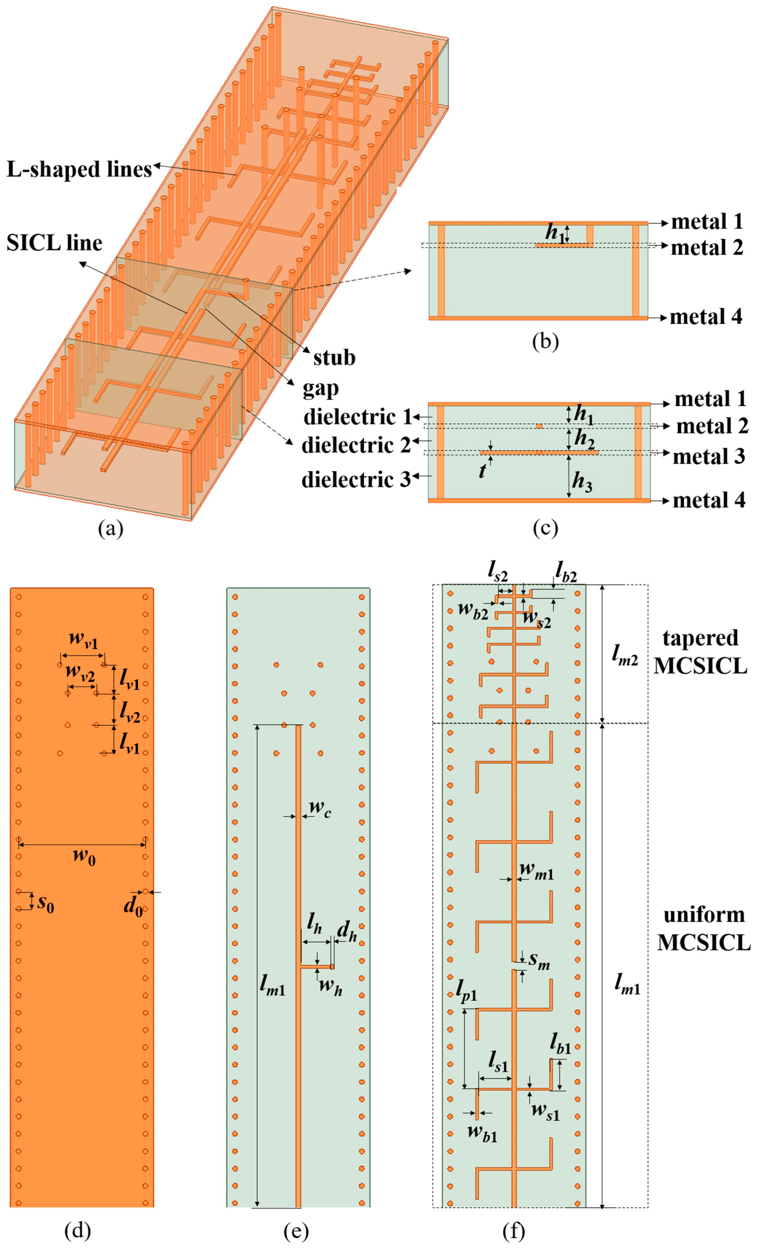
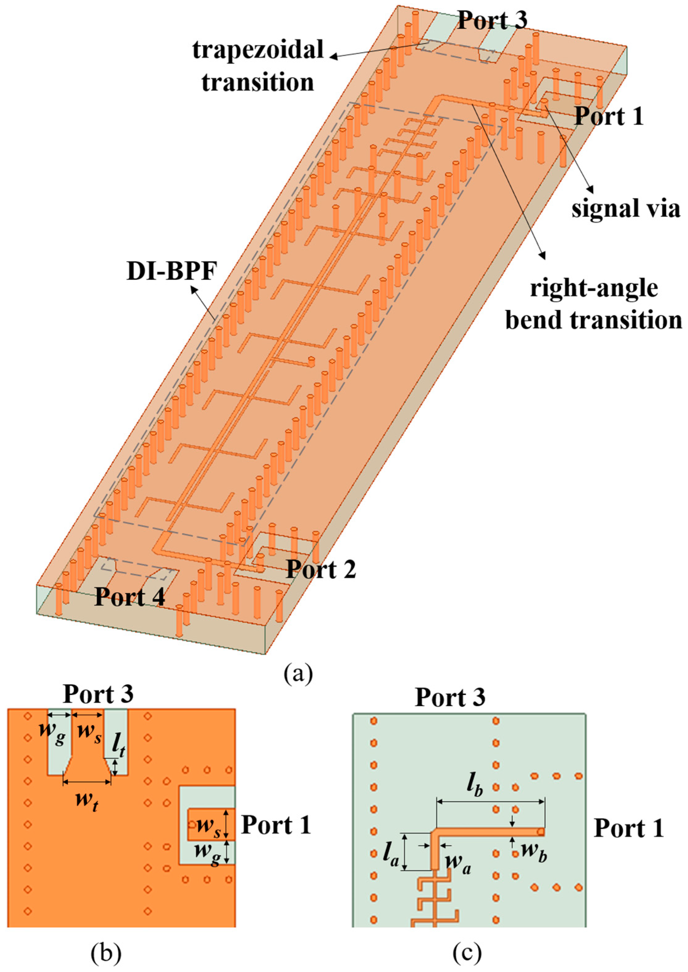
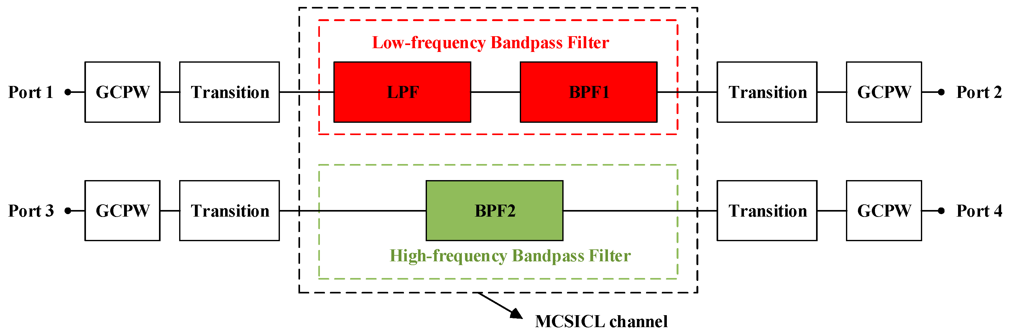
2. Structures of the Proposed DI-BPF

2.1. The Proposed DI-BPF

The proposed DI-BPF is based on the MCSICL structure. It has four metal layers and three dielectric layers, as shown in Figure 1. The thicknesses of the four metal layers 1–4 are all t, and the thicknesses of the dielectric layers 1–3 are h1, h2 and h3, respectively.
The MCSICL has two parts: the uniform MCSICL with a length of lm1 and the tapered MCSICL with a length of lm2. The outer conductors are grounds, located on metal 1 and 4, and the inner conductor with L-shaped lines is a signal line located on metal 3. The width of the inner conductor is wm1. The L-shaped line consists of a straight line and a bent line. In the uniform MCSICL, the length and width of the straight line are ls1 and ws1, respectively; the length and width of the bend lines are lb1 and wb1, respectively, and the distances of each pair of L-shaped structures are lp1. In the tapered MCSICL, there are six pairs of L-shaped lines with different sizes. The minimum length and width of the straight line are ls2 and ws2, respectively; and the minimum length and width of the bend lines are lb2 and wb2, respectively.
To form the low-frequency bandpass filter, an SICL line with a stub is incorporated into the MCSICL with a gap. The SICL line with the stub is designed on metal 2. The length and width of the SICL line are lm1 and wc, respectively. One end of the stub is connected to the SICL line and the other end is connected to the ground through the via. The length and width of the stub are lh and wh, respectively. The diameter of the via is dh. The gap is designed in the middle of the inner conductor of the uniform MCSICL. The width of the gap is sm.
To form the high-frequency bandpass filter, eight grounded vias are designed to connect metal 1 and metal 4 of the MCSICL, symmetrically distributed along the inner conductor. The distances of two grounded vias in one row are wv1 and wv2, and the distances of two grounded vias in one column are lv1 and lv2, respectively.

2.2. The Transition Structure

The proposed DI-BPF with the transitions is presented in Figure 2. For the low-frequency bandpass filter, the proposed DI-BPF is connected to GCPWs through the right-angle bend transition, and its input and output are set as ports 1 and 2, respectively. The right-angle bend transition consists of two lines perpendicular to each other and a signal via connected to the signal conductor of the GCPW. The length and width of the vertical line are la and wa, respectively, and the length and width of the horizontal line are lb and wb, respectively. For the high-frequency bandpass filter, the proposed DI-BPF is connected to GCPWs through the trapezoidal transition, and its input and output are set as ports 3 and 4, respectively. The length and wide-side width of the trapezoidal transition are lt and wt, respectively. In the GCPW, the width of the central conductor is ws, and the distance between the central conductor and the bilateral ground strip is wg.

3. Design Principle of the Proposed DI-BPF

Figure 3 shows the schematic layout of the proposed DI-BPF with the transitions, which designs a low-frequency bandpass filter and a high-frequency bandpass filter based on the MCSICL.

3.1. Low-Frequency Bandpass Filter

The low-frequency bandpass filter is composed of the bandpass filter 1 (BPF1) and the low-pass filter (LPF), which equivalent circuit model is shown in Figure 4.
The BPF1 is designed by combining an SICL line with a stub and the uniform MCSICL with a gap. The SICL line and the uniform MCSICL form a pair of parallel-coupled lines, which have even-/odd-mode characteristic impedance Zoe/Zoo and unit electrical length θp1. The stub has a characteristic impedance of Zh and an electrical length of θh. The gap is modeled as a capacitor Cg. An L-shaped line consists of two lines: one line with the characteristic impedances of Zs1 and the electrical lengths of θs1, and the other line with the characteristic impedances of Zb1 and the electric lengths of θb1.
The LPF models the tapered MCSICL, which improves isolation between the low- and high-frequency bandpass filters. The tapered MCSICL can be looked at as an SICL with L-shaped stubs. The SICL has the characteristic impedance Zm1 and a unit electrical length of θp2. The minimum L-shaped stub also consists of two lines: one line with characteristic impedances of Zs2 and the electrical lengths of θs2 and the other line with characteristic impedances of Zb2 and the electric lengths of θb2.

3.2. High-Frequency Bandpass Filter

The high-frequency bandpass filter is BPF2, which is formed by an SIW with eight grounded vias [19]. The BPF2 is modeled as a 3-order Chebyshev SIW bandpass filter [19]. The equivalent circuit of the BPF2, which is exactly like that in [19], consists of four elements in cascade, and each element includes a K-inverter and a quarter-wavelength open-ended transmission line on each side of the K-inverter. The impedance values of the normalized K-inverters are calculated as follows [19]:
K 01 = λ 1 λ 0 π FBW 2 g 0 g 1
K m , m + 1 = π FBW 2 λ 1 λ 0 2 g m g m + 1 m = 1 , 2
K 34 = λ 1 λ 0 π FBW 2 g 3 g 4
where gm is the prototype value, λ1 is the guided wavelength in SIW of the center frequency of f2, λ0 is the free-space wavelength of f2, FBW is the fractional bandwidth. The S21-parameter of k-th element can be calculated by [19]
S 21 = j 2 K k 1 , k 1 + K k 1 , k 2
where k = 1, 2, 3, 4. Given the center frequency f2 and the FBW, the S21 of each element can be calculated based on (1)–(4).

4. Experimental Results and Discussion

4.1. Design and Fabrication

The proposed DI-BPF with transitions is designed by the PCB process. Rogers 5880,manufactured from Shenzhen Shangjihong Circuit Technology Company, is used as a dielectric material, which has a permittivity of 2.2 and a loss tangent of 0.0009. Copper is used as a metal material, which has a conductivity of 1.67 × 10⁻⁶ Ω·cm. To adhere the layers of the proposed DI-BPF with transitions, adhesive layers of 4450 PP are introduced between the dielectric 1 and the metal 2 and between the metal 3 and the dielectric 3, respectively. The 4450 PP has a thickness of 0.1 mm, a permittivity of 3.5, and a loss tangent of 0.002.
The photographs of the proposed DI-BPF with the transitions are shown in Figure 5, and the dimensions are summarized in Table 1. The dimensions are determined as follows.
As for the low-frequency bandpass filter, the objective performance includes the center frequency f1 1.9 GHz, the FBW 15% and the stopband suppression 20 dB from 3 GHz to 50 GHz. The equivalent circuit parameters shown in Table 2 are obtained using Advanced Design System (ADS) software. Subsequently, the dimensions of the low-frequency bandpass filter are optimized through High Frequency Structure Simulator (HFSS) simulations.
As for the high-frequency bandpass filter, the center frequency f2 is set to be 44 GHz with a FBW of 11.3%. Based on (1)–(3), the equivalent circuit parameters of the high-frequency bandpass filters are obtained, which are also shown in Table 2. Subsequently, the dimensions of the high-frequency bandpass filter are optimized through HFSS simulations.
As for the transitions, the dimensions are optimized through HFSS simulations.

4.2. Verification of the Equivalent Circuit Models

To verify the proposed equivalent circuit models, the S-parameters obtained from the equivalent circuit models are compared with those from the full-wave simulation software, as shown in Figure 6. The results demonstrate a basic agreement, indicating the accuracy of the equivalent circuit models. As for the results of the low-frequency bandpass filter illustrated in Figure 6a, the S-parameters acquired from the equivalent circuit model exhibit a commendable agreement with those obtained from the full-wave simulation software. As for the results of the high-frequency bandpass filter depicted in Figure 6b, both the S-parameters obtained from the equivalent circuit model and the full-wave simulation software demonstrate consistent trends, although there are slight deviations in values. The deviation primarily manifests in discrepancies in the insertion loss at the passband range. Notably, the insertion loss attained through the full-wave simulation software is inferior to that obtained via the equivalent circuit model. This discrepancy arises because the full-wave simulation closely resembles the actual situation with loss, whereas the equivalent circuit model represents an ideal scenario. Furthermore, this disparity becomes increasingly apparent at higher frequencies.

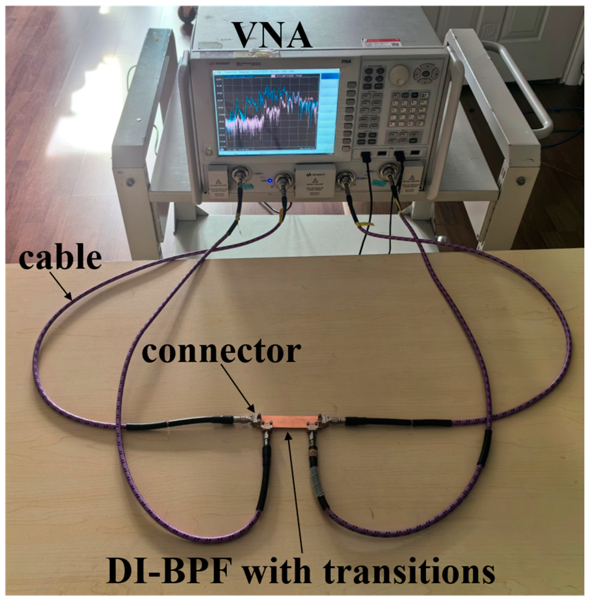
4.3. Experimental Setup

The fabricated DI-BPF with transitions is measured by a four-port test system, as shown in Figure 7. The fabricated DI-BPF with transitions is fixed on a table and is connected to a Keysight N5227A Vector Network Analyzer (VNA) by four 1.85 mm connectors and four 1.85 mm coaxial cables. Four-port calibrations are performed with short-open-load-thru (SOLT) standards to mitigate the impact of the connectors and the cables. Subsequently, the S-Parameters and the isolation performance of the DI-BPF with transitions can be measured.

4.4. Simulation and Measurement Results

The simulated and measured S-parameters of the proposed DI-BPF with transitions are shown in Figure 8a–c. The measured results basically agree with those of the simulated ones. Figure 8a shows the simulated and measured S-parameters of the low-frequency bandpass filter. The simulated results of the low-frequency bandpass filter demonstrate a FBW of 15%, an insertion loss of 0.84 dB and a return loss of 19 dB at the center frequency of 1.9 GHz. The insertion loss remains below 2.0 dB and the return loss exceeding 10.5 dB in the low-frequency passband of 1.76–2.04 GHz. In contrast, the measured results of the low-frequency bandpass filter acquire the FBW of 15.7%, the insertion loss of 1.3 dB and the return loss of 16 dB at the center frequency of 1.9 GHz, and the insertion loss remains below 2.2 dB and the return loss exceeds 10.6 dB in the low-frequency passband of 1.75–2.05 GHz. Figure 8b shows the simulated and measured S-parameters of the high-frequency bandpass filter. The simulated results demonstrate the FBW of 11.1%, the insertion loss of 1.6 dB and the return loss of 27 dB at the center frequency of 44 GHz, and the insertion loss below 2.5 dB and the return loss exceeding 10 dB in the high-frequency passband of 41.6–46.5 GHz. In contrast, the measured results of the high-frequency bandpass filter acquire the FBW of 10.4%, the insertion loss of 1.9 dB and the return loss of 20 dB at the center frequency of 44 GHz, and the insertion loss below 2.7 dB and the return loss exceeding 10 dB in the high-frequency passband of 41.7–46.3 GHz. Figure 8c shows the simulated and measured isolation between the low-frequency bandpass filter and the high-frequency bandpass filter. The simulated |S31| and |S41| are lower than −33 dB, while the measured |S31| and |S41| are lower than −30 dB, which shows that the isolation between the two filters is high. Due to the calibration that has mitigated the impact of cables and connectors on measurement results, there exists only a slight discrepancy between the measured results and the simulated results. The slight discrepancy is mainly attributed to the manufacturing error.
In addition, the Electric (E-) field distributions of the proposed DI-BPF with transitions at 1.9 GHz and 4.4 GHz are presented in Figure 9. The E-field distribution intuitively illustrates that the proposed DI-BPF with transitions can transmit in the low-frequency band with a center frequency of 1.9 GHz and in high-frequency band with a center frequency of 44 GHz.

4.5. Comparisons

The comparisons among the proposed DI-BPF and other bandpass filters with dual-band [7,8,9,10,11,12,13,15,19] are shown in Table 3. The dual-band bandpass filters based on SIW [7], ML [9] and the dual-band integrated bandpass filter based on RWs [11,12,13] exhibited lower insertion loss; however, their frequency ratios were small, and their sizes were not compact. The dual-band integrated bandpass filters based on MCTL [15] and MCCPW [19] achieved larger frequency ratios of 6.67 and 21.2, respectively, attributed to independent designs for the low and high passbands. Nevertheless, the sizes of filters [15,19] were not compact due to the presence of two passbands created at two physical channels. The proposed DI-BPF, based on MCSICL, attains the largest frequency ratio of 23.16 and the smallest size of 0.019 λg2. The large frequency ratio arises from the independent design of its low and high passbands. The compact size is attributed to the creation of two passbands in a single physical channel and the slow-wave effect of periodic L-shaped lines. However, this compact design comes at the expense of a modest increase in insertion loss and a reduction in isolation. The isolation of the DI-BPF is slightly inferior to that in [13,15] but superior to that in [11,12,19].

5. Conclusions

In this paper, a DI-BPF based on an MCSICL is proposed by integrating a low-frequency bandpass filter and a high-frequency bandpass filter. The low- and high-frequency bandpass filters are designed based on the fundamental mode and the first high-order mode of the MCSICL. The equivalent circuit models are proposed to guide the designs. The transitions from DI-BPF to GCPWs are designed. The proposed DI-BPF with transitions is fabricated under the PCB process. The measurement results show that the proposed DI-BPF has a large frequency ratio and a compact size. Therefore, the proposed DI-BPF can be used in 5G technology for simultaneously transmitting FR1 and FR2 signals.

Author Contributions

Conceptualization, Y.Z. and X.L.; methodology, Y.Z.; validation, Y.Z. and X.L.; formal analysis, Y.Z.; investigation, Y.Z.; resources, X.L.; data curation, Y.Z.; writing—original draft preparation, Y.Z.; writing—review and editing, X.L.; funding acquisition, X.L. All authors have read and agreed to the published version of the manuscript.

Funding

This research was supported by the National Natural Science Foundation of China under Grant 62188102 and 62371284.

Data Availability Statement

Data are contained within the article.

Conflicts of Interest

The authors declare no conflicts of interests.

References

  1. Loung, V.Y.K.; Ngah, R.; Owusu, J.; Han, C.T.; Koduah, S.T.; Din, J. Key technologies and future trends of 5G wireless network applications. In Proceedings of the IEEE 6th International Conference Signal Image Process (ICSIP), Nanjing, China, 22–24 October 2021; pp. 908–914. [Google Scholar]
  2. Rappaport, T.S.; Sun, S.; Mayzus, R.; Zhao, H.; Azar, Y.; Wang, K.; Wong, G.N.; Schulz, J.K.; Samimi, M.; Gutierrez, F. Millimeter wave mobile communication for 5G cellular: It will work! IEEE Access 2013, 1, 335–349. [Google Scholar] [CrossRef]
  3. Tang, W.S.; Zheng, S.Y.; Pan, Y.M.; Liu, H.W. A Frequency independently tunable dual-band bandpass filter with large frequency ratio and ultra-wide stopband. IEEE Trans. Ind. Electron. 2023, 70, 1894–1904. [Google Scholar] [CrossRef]
  4. Pang, X.D.; Hong, W.; Yang, T.Y.; Li, L.S. Design and implementation of an active multibeam antenna system with 64 RF channels and 256 antenna elements for massive MIMO application in 5G wireless communications. China Commun. 2014, 11, 16–23. [Google Scholar]
  5. Bhat, Z.A.; Sheikh, J.A.; Khan, S.D.; Bashir, I.; Parah, S.A. A new method of isolation enhancement of dual-band bandpass filter using composite mode coplanar waveguide structure for 5G and body centric applications. Iran. J. Sci. Technol. Trans. Electr. Eng. 2022, 47, 317–326. [Google Scholar] [CrossRef]
  6. Xu, J.X.; Zhang, X.Y.; Li, H.Y.; Yang, Y.; Dutkiewicz, E.; Xue, Q. Ultracompact multichannel bandpass filter based on trimode dielectric-loaded cavities. IEEE Trans. Microw. Theory Technol. 2020, 68, 1668–1677. [Google Scholar] [CrossRef]
  7. Chaudhury, S.S.; Awasthi, S.; Singh, R.K. Dual-band bandpass filter based on substrate integrated waveguide loaded with mushroom resonators. Microw. Opt. Technol. Lett. 2020, 62, 2226–2235. [Google Scholar] [CrossRef]
  8. Krishna, I.S.; Mukherjee, S. Fully shielded and self-packaged compact quarter-mode substrate integrated coaxial line bandpass filter for X and K-band. Int. J. RF Microw. Comput. Aided Eng. 2022, 32, e23529. [Google Scholar] [CrossRef]
  9. Liang, G.Z.; Chen, F.C. A compact dual-wideband bandpass filter based on open-/short-circuited stubs. IEEE Access 2020, 8, 20488–20492. [Google Scholar] [CrossRef]
  10. Wang, X.D.; Wang, J.P.; Zhu, L.; Choi, W.W.; Wu, W. Compact stripline dual-band bandpass filters with controllable frequency ratio and high selectivity based on self-coupled resonator. IEEE Trans. Microw. Theory Technol. 2020, 68, 102–110. [Google Scholar] [CrossRef]
  11. Xu, J.X.; Zhang, X.Y. Dual-channel dielectric resonator filter and its application to Doherty power amplifier for 5G Massive MIMI system. IEEE Trans. Microw. Theory Technol. 2018, 66, 3297–3305. [Google Scholar] [CrossRef]
  12. Xu, L.; Yu, W.; Chen, J.X. Design of dual-channel filter based on dual-mode dielectric resonators. IEEE Trans. Circuits Syst. Ⅱ Exp. Briefs. 2022, 69, 45–49. [Google Scholar] [CrossRef]
  13. Xu, J.X.; Huang, M.; Song, S.L.; Li, H.Y. Compact multichannel filters and multiplexers based on dual-coaxial resonators. IEEE Trans. Circuits Syst. Ⅱ Exp. Briefs. 2022, 69, 4664–4668. [Google Scholar] [CrossRef]
  14. Su, Y.H.; Lin, X.Q.; Yu, J.W.; Fan, Y. Mode composite coplanar waveguide. IEEE Access 2019, 7, 109278–109288. [Google Scholar] [CrossRef]
  15. Yang, S.L.; Xu, J.; Yu, Z.Q.; Zhou, J.Y.; Hong, W. A structure reuse method for realizing large frequency ratio dual-band multi-channel integrated filters. IEEE Trans. Circuits Syst. Ⅱ Exp. Briefs. 2022, 69, 2101–2105. [Google Scholar] [CrossRef]
  16. Li, Y.J.; Wang, J.H. Dual-band leaky-wave antenna based on dual-mode composite microstrip line for microwave and millimeter-wave applications. IEEE Trans. Antennas Propag. 2018, 66, 1660–1668. [Google Scholar] [CrossRef]
  17. Su, Y.H.; Lin, X.Q.; Fan, Y.; Wu, K. Mode composite sandwich slot line and its applications in antenna development. IEEE Trans. Antennas Propag. 2020, 68, 4250–4258. [Google Scholar] [CrossRef]
  18. Zhu, Y.; Li, X.C.; Mao, J.F. Mode composite substrate integrated coaxial line based on substrate integrated coaxial line and L-shaped SSPP structure. IEEE Trans. Compon. Packag. Manuf. Technol. 2023, 13, 528–536. [Google Scholar] [CrossRef]
  19. Su, Y.H.; Fan, Y.; Lin, X.Q.; Wu, K. Single-layer mode composite coplanar waveguide dual-band filter with large frequency ratio. IEEE Trans. Microw. Theory Technol. 2020, 68, 2320–2330. [Google Scholar] [CrossRef]
Figure 1. Structure of the proposed DI-BPF. (a) 3D view, (b,c) cross-section views, (d) metal layer 1 or 4, (e) metal layer 2, (f) metal layer 3.
Electronics 13 00754 g001
Figure 2. Structures of the proposed DI-BPF with transitions. (a) 3D view, (b) metal 1 of the transitions, (c) metal 3 of the transitions.
Electronics 13 00754 g002
Figure 3. Schematic layout of the proposed DI-BPF with transitions.
Electronics 13 00754 g003
Figure 4. The equivalent circuit model of the low-frequency bandpass filter.
Electronics 13 00754 g004
Figure 5. Photographs of the fabricated DI-BPF with transitions.
Electronics 13 00754 g005
Figure 6. S-parameter of the proposed DI-BPF without transitions. (a) The low-frequency bandpass filter, and (b) the high-frequency bandpass filter.
Electronics 13 00754 g006
Figure 7. Four-port test system for measuring the fabricated DI-BPF with transitions.
Electronics 13 00754 g007
Figure 8. Simulated and measured S-parameter of the proposed DI-BPF with transitions. (a) The low-frequency bandpass filter, (b) the high-frequency bandpass filter, (c) the isolation between the filters.
Electronics 13 00754 g008
Figure 9. E-field distributions of the proposed DI-BPF with transitions. (a) at 1.9 GHz, and (b) at 44 GHz.
Electronics 13 00754 g009
Table 1. The dimensions of the proposed DI-BPF with transitions. Unit: mm.
Para.ValuesPara.ValuesPara.ValuesPara.Values
w04s00.5d00.2t0.018
h10.127h20.127h30.254wv12.15
wv21.2lv12.05lv22.3wc0.2
lm142.1lh1.75wh0.12dh0.2
wm10.15lp17lm28sm0.1
ls11.425lb13.05ws10.15wb10.15
ls20.425lb20.65ws20.15wb20.15
wa0.4la1.45wb0.4lb4.2
ws1.6wg1lt0.67wt2.39
Table 2. Values of the equivalent circuit parameters.
Para.ValuesPara.ValuesPara.ValuesPara.Values
θs15.8°θb112.3°θp127.5°θs21.7°
θb22.6°θp2θh6.66°Zoe173 Ω
Zoo70.2 ΩZh110 ΩCg0.8 fFZs1, Zb194.2 Ω
Zs2, Zb294.2 ΩZm194.2 ΩK010.4805K120.1859
K230.1859K340.4805----
Table 3. Comparison with other bandpass filters with dual-bands.
Ref.TypeFreq. (GHz)f2/f1IL (dB)Isolation (dB)Size (λg × λg)
f1f2f1f2
[7]SIW2.24.181.911.8-0.112
[9]ML2.45.22.10.30.7-0.056
[11]RW3.5253.52510.320.3225.30.176
[12]RW1.531.681.10.680.6824.50.084
[13]RW2.813.321.180.320.41800.054
[15]MCTL4.2286.670.62.7540.508
[19]MCCPW1.653521.10.61.8280.052
This WorkMCSICL1.94423.161.31.9300.019
IL: Insertion Loss; λg is the guide wavelength of f1.
Disclaimer/Publisher’s Note: The statements, opinions and data contained in all publications are solely those of the individual author(s) and contributor(s) and not of MDPI and/or the editor(s). MDPI and/or the editor(s) disclaim responsibility for any injury to people or property resulting from any ideas, methods, instructions or products referred to in the content.

