Article

Enhancing Frequency Regulation Support through Several Synthetic Inertial Approaches for WDPS

by
Muhammad Asad
* and
Jose Angel Sanchez-Fernandez
Department of Hydraulic, Energy and Environmental Engineering, E.T.S.I. Caminos Canales y Puertos, Universidad Politécnica de Madrid, 28040 Madrid, Spain
*
Author to whom correspondence should be addressed.
Electronics 2024, 13(5), 852; https://doi.org/10.3390/electronics13050852
Submission received: 18 January 2024 / Revised: 19 February 2024 / Accepted: 20 February 2024 / Published: 23 February 2024

Abstract

:
The aim of this paper is to propose an enhancement to the primary frequency control (PFC) of the San Cristobal Island hybrid wind–diesel power system (WDPS). Naturally, variable speed wind turbines (VSWT) provide negligible inertia. Therefore, various control strategies, i.e., modified synthetic inertial control, droop control and traditional inertial control, if introduced into VSWT, enable them to release hidden inertia. Based on these strategies, a WDPS has been simulated under seven different control strategies, to evaluate the power system performance for frequency regulation (FR). Furthermore, the student psychology-based algorithm (SBPA) methodology is used to optimize the WDPS control. The results show that modified synthetic inertial control is the most suitable approach to provide FR. However, further exhaustive research validates that droop control is a better alternative than modified synthetic inertial control due to the negligible system performance differences. In addition, droop control does not require a frequency derivative function in the control system. Therefore, the hybrid system is more robust. Moreover, it reduces the steady state error, which makes the power system more stable. In addition, a pitch compensation control is introduced in blade pitch angle control (BPAC) to enhance the pitch angle smoothness and to help the power system to return to normal after perturbations. Moreover, to justify the performance of hybrid WDPS, it is tested under certain real-world contingency events, i.e., loss of a wind generator, increased wind speed, fluctuating wind speed, and simultaneously fluctuating load demand and wind speed. The simulation results validate the proposed WDPS control strategy performance.

1. Introduction

Trends towards hybrid power plants or to enrich conventional power plants with renewable energy sources (RES) have dramatically increased in recent decades. This leads to several benefits like reductions in greenhouse gas emissions, in the dependency on and depletion of fossil fuels, in economic and environmental costs (particularly on isolated islands), etc., [1]. On the other hand, the penetration of RES can cause problems for conventional power systems. Due to recent developments in technology, especially in power electronics, wind energy is the most adaptable renewable energy resource merged in isolated island power networks. Notwithstanding, these power systems require ancillary services. In addition, as the penetration of wind energy into electrical power systems increases, system operators must deal with several new challenges to ensure the reliability, quality, and stability of these electrical power systems.
Wind energy is intermittent in nature, both spatially and temporally. This can result in an imbalance between generation and demand [2]. One of the major concerns in the operation of power systems as a result of such an imbalance is frequency deviations (FD) [3]. The most common practice for frequency control, specifically in Europe, has a hierarchical structure usually organized into three categories, i.e., primary, secondary and tertiary control, divided into five layers of protection (from fast to slow timescales) [4,5]. For small FD (<1% of nominal frequency), the primary control actuation time lies between 2 and 20 s. In certain rare events of mismatches between production and consumption, due to the intermittent nature of RES, the control hierarchy has failed to provide protection to some islanded power systems, so load shedding or blackouts have occurred [4]. A real event that justifies the above situation happened in the San Cristobal Island hybrid wind–diesel power system (WDPS). It is located at the Galapagos Islands, Ecuador, where the high penetration of wind energy in the load sharing caused partial and total power outages during the windiest season in 2015 [6]. Therefore, this paper uses the San Cristobal Island hybrid WDPS as a case study for primary frequency control (PFC) protection.
In [7,8], the authors described that the impact of RES on electrical power systems (EPS) majorly depends on the system inertia and penetration rate. Synchronous generators in conventional power plants, while operating in hybrid mode, dramatically lose their inertial response against FD due to high wind penetration. This situation may be worse for island power systems. In the literature, various solutions to mitigate these negative effects have been presented. Lazarewicz [9] discussed the positive effects of a fly wheel-based energy storage system for frequency regulation (FR). Energy storage systems like fly wheels, batteries or capacitors improve the FD problems by absorbing the fluctuating power generated by wind turbines. However, these solutions have disadvantages in terms of maintenance and installation costs. In [10], FR was provided for hybrid power systems using a PID controller and genetic algorithm. Similarly, a squirrel search algorithms-based cascade fractional order controller [11] minimized the FD in the wake of load variation. A novel meta heuristic, derivative-free method named as a quasi-oppositional harmony search algorithm was used to improve the frequency stability in hybrid power systems [11]. Furthermore, sliding mode control [12,13], the bacterial foraging algorithm [14], artificial bee colony algorithm [15], etc., are used to overcome the FD problems in isolated hybrid power systems.
Currently, there is a global consensus in terms of topology about installed wind turbines in various power systems. Based on these topologies, wind turbines are divided into four types depending on the type of electrical generator (induction and synchronous) used and its configuration within the EPS [16,17,18]. However, wind turbines based on doubly-fed induction generators (DFIG) are the ones that lead the selection and implementation preferences because they have attained most of the market share in the last decade in most EPS [19,20,21,22,23,24]. Such wind turbines have the capabilities to perform their function within a wide range of angular velocities in response to fluctuating wind. Therefore, these wind turbines are termed as variable speed wind turbines (VSWT). Currently, VSWT account for more than 650 GW of the installed capacity around the world [25]. VSWT can mitigate large FD, thus providing FR in EPS. Traditionally, VSWT do not contribute to the system inertia because they lack a natural inertial response or cannot naturally provide the kinetic energy stored in their rotor and generator. However, with the modification of VSWT control loops, it is possible to achieve an inertial response. With this aim, different frequency control approaches can be found in the specific literature [26,27], shown in Figure 1. However, even though de-loading control strategies can enhance the long-term FR, they are not economically viable solutions for wind power plants’ operators, due to the loss of profits [28]. Therefore, inertial response control strategies are preferred in this row. Gonzalez et al. [29] evaluated two inertial response strategies, i.e., fast power reserve (FPR) and hidden inertia emulation (synthetic inertia). It is concluded that for high-inertia systems the most suitable control strategy is FPR, while for low inertia systems, the virtual inertia emulated technique is the best. With such objective, Renuka [30] used an inertial emulation control strategy for enhancing FR by reducing the minimum FD (NADIR).
Furthermore, DFIG-based VSWT also provide PFC regulation. Different studies have been carried out to evaluate the impact of DFIG-based wind turbines, particularly VSWT on power systems. The main objective of PFC regulation is to stabilize the frequency to a new value by modifying the power generation proportional to FD [8]. Therefore, PFC regulation can be combined with an inertial emulation control strategy [31,32]. With this aim, the inertial response of power system was enhanced by adding a control loop with inertial emulation control in [33] that reduced the FD. Based on this strategy, several models can be found in the literature [34,35,36]. In these models, only one loop of inertial emulation is implemented, meaning that the power exchange (∆p) is proportional to the rate of change of frequency (RoCoF). However, Morren et al. [37] and Mauricio et al. [38] presented a modified, two-loop inertial control strategy by adding a proportional control that weights the FD (∆p ∝ ∆f). Further studies based on this two-loop strategy were carried out in [8,39,40]. Therefore, DFIG-based VSWT with this two-loop inertial emulation control are used in this research paper. One of the major advantages of this control is to operate the DFIG-based VSWT at their optimum operational point (OOP). Otherwise, non-OPP leads to inevitable economic losses in VSWT [41]. Furthermore, this control allows better usage of wind resources because it does not need any regulation reserve.
The main contributions of this paper are as follows:
(1)
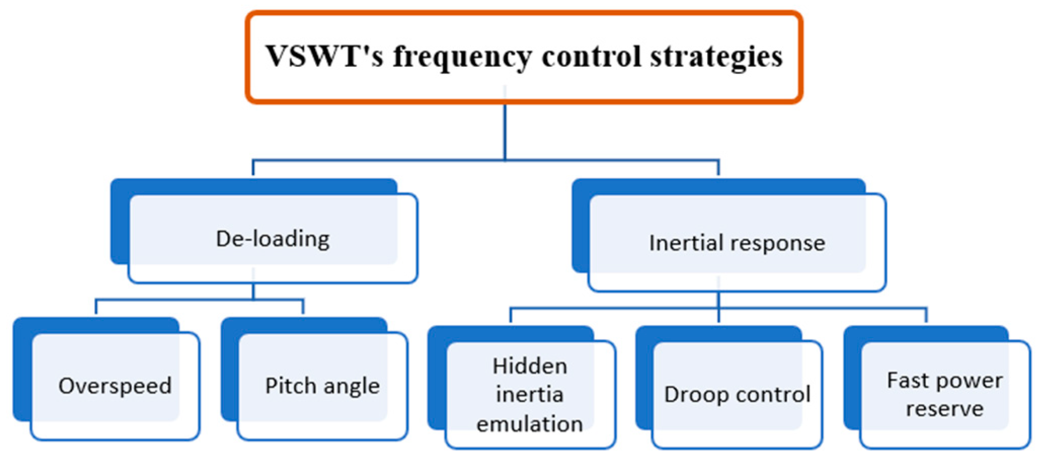
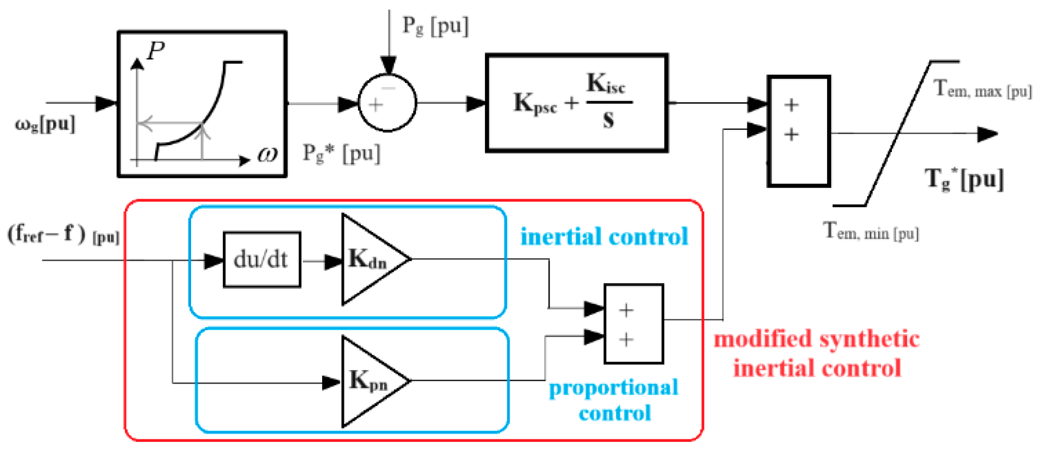
New controls were introduced (modified synthetic inertial control, droop control, traditional inertial control) into VSWT that enable them to contribute, by releasing synthetic inertia, during contingencies;
(2)
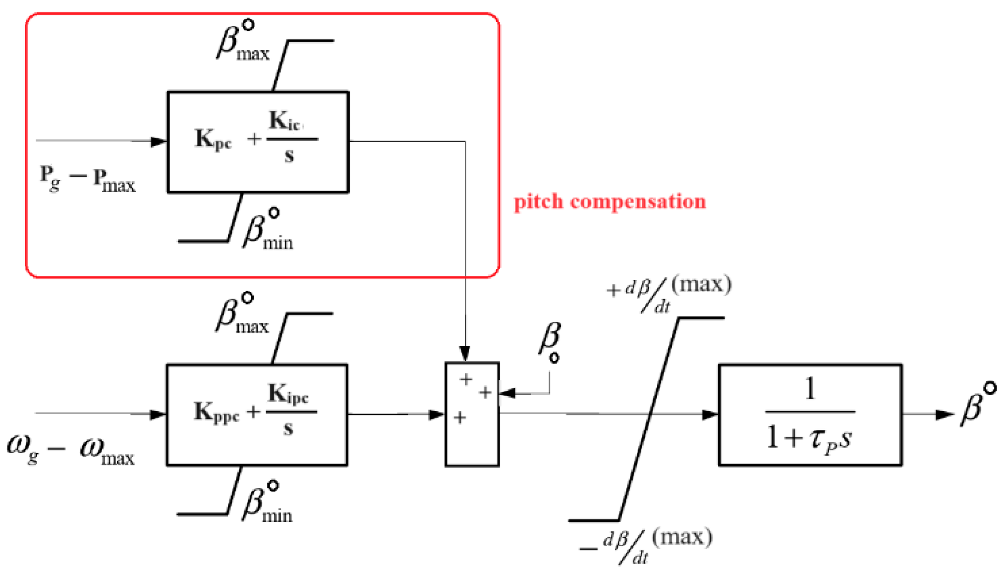
Pitch compensation control was introduced in BPAC that returned the system to normal after perturbations. In addition, it enhanced the BPAC smoothness;
(3)
The SPBA optimization algorithm is used to optimally tune the hybrid power system. Major benefits are achieved by using SPBA, as discussed in Section 5;
(4)
The hybrid WDPS control strategies’ performance was evaluated and compared against seven different scenarios to highlight their pros and cons. Moreover, it is concluded that droop control is the best alternative to modified synthetic inertial control in terms of robustness because it reduced noise by eliminating the derivative function from the control loop. Moreover, it reduced the steady-state error which made the power system more stable;
(5)
The controller performance was tested under various real-world scenarios to highlight its reliability.
This paper is organized as follows: Section 2 and Section 3 briefly describe the modeling of wind turbines and diesel power plants, respectively. In Section 4, proposed control strategies for WT are explained in detail. Similarly, the student psychology-based algorithm (SPBA) optimization methodology is discussed in Section 5. Section 6 covers a detailed discussion of various scenarios of WDPS with or without the proposed control strategies. Moreover, controller performance under real-world scenarios (load fluctuation, wind fluctuation, simultaneous wind and load fluctuation, etc.) is explained in Section 7. Finally, conclusions are provided in Section 8.

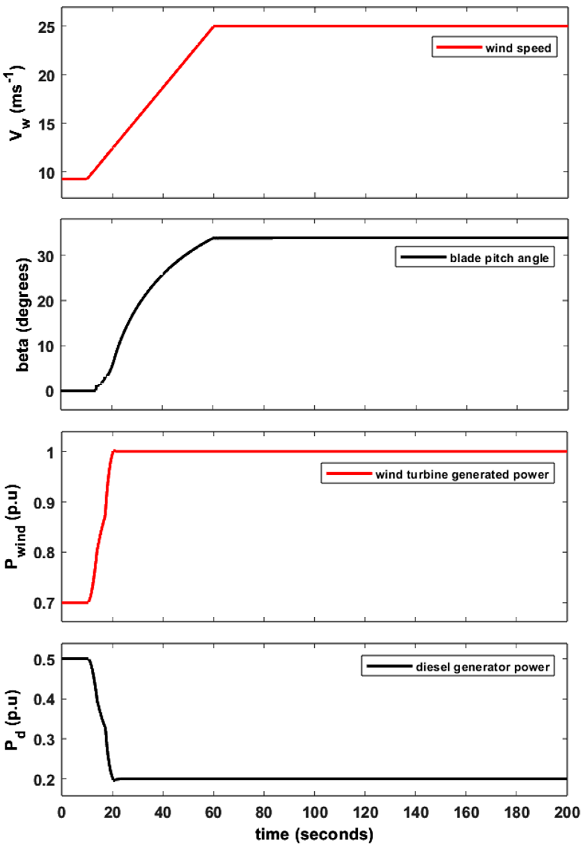
2. Wind Turbine Modeling

Wind turbines (WT) are electromechanical devices that extract kinetic energy (K.E) from wind termed as wind energy, transmit it into their rotational shafts as mechanical energy (M.E) and then transform it into electrical energy (E.E). As mentioned above, this paper focuses on Type 3 wind turbines, due to their variable speed operation (±33% around synchronous speed), high efficiency, low mechanical stress, four quadrant power capability, low converter rating, etc., [42]. A general schematic of DFIG-based VSWT is shown in Figure 2. It clearly shows that this model has four subsystems, i.e., an aerodynamic system (ADS), mechanical system (MS), converter system (CS) and generating system (GS). The ADS is composed of a three-blade wind turbine rotor. ADS harness the wind energy. The MS represents a two-mass model or gear box (GB) that shows both high and low speed sides of the GB. The shaft of a wind turbine rotor is coupled to the shaft of an electric generator through a GB. Furthermore, the GS represents the DFIG, also termed as doubly fed asynchronous generator, which provides the current (both active and reactive) injected into the electric grid. Therefore, the rotor side terminals of DFIG are connected to the electric grid through power electronics converters to extract maximum wind power but the stator side terminals are directly connected to the electric grid. The CS is composed of two back-to-back converters named the generator side converter (GSC) and line side converter (LSC) connected through a direct current (DC) link. The DC link is responsible for the exchange of active power. The GSC is responsible for reactive power (Q) in the asynchronous stator, while the LSC is responsible for regulating the voltage of the DC link. In addition, GSC also controlled the active power (P) with the help of a maximum power point tracking MPPT system. Moreover, the CS enables the generator to operate within a wide range of speed variations. Now, we start modeling each system of a wind turbine one by one in detail below.
The mathematical representation of the power extracted from the wind is given in (1). Here, Kpow represents a power constant, Vw is the wind speed and Cp is the power coefficient. Similarly, ρ, R, D, λ and β denote the air density (kg/m3), turbine radius (m), turbine diameter (m), relative turbine speed and blade pitch angle in degrees, respectively.
Ptur [p.u.] = KpowVw3Cp (λ, β)
where
K p o w = 1 2   ρ π R 2 P b a s e , [ W ]
The relative turbine speed, λ, is the ratio of the rotor blade tip speed and wind speed, Vw.
λ = K v ω t [ p . u . ] V w [ m s 1 ]
where
K v = ω t , b a s e [ r a d / s ] D ( m ) 2
Similarly, other subsystems of WT are (1) the mechanical system (5) where ΔT = Tt − Tg. Thus Tt, Tg and Hi represent the turbine generated torque, converter-demanded torque, and inertia constant, respectively, (2) generator and electronic converters (Figure 3) where Tg* shows the torque generated by the speed controller and tc represents the time constant of the first-order actuator, (3) the blade pitch angle control (BPAC) (Figure 4) where, tp represents a delay constant or servomotor time constant. Similarly, kppc and kic are PI controller gains used to perform regulatory actions in BPAC (4) maximum power point tracking (MPPT) (6).
ω t t = Δ T 2 H i
P g * = ω g ω m i n ω 0 ω m i n K o p t ω 0   ω m i n ω g   ω 0 ω g 3 K o p t                                                             ω 0 ω g   ω 1 ω g ω m a x P m a x K o p t ω 1 3 ω m a x ω 1 + P m a x   w h e n   ω 1 < ω g < ω m a x P m a x                                                                                   ω g ω m a x

3. Diesel Power Plant Modeling

In general, a diesel power plant (DPP) is a conventional electric power generating station that uses fuel oil to produce electric energy. Figure 5 represents the general schematic of the CAT-3512DITA San Cristobal Island DPP model that the authors built in their previous work [43]. All other parameters of a diesel engine are given in Table 1.

4. Proposed Control Loop: San Cristobal Island WT

VSWT do not contribute to PFC. The major reason that justifies this statement is the non-optimal wind turbine operation [8,44] that inevitably leads to economic loss [41]. Furthermore, VSWT provide negligible or no inertial support during contingencies. During hybrid operations, only the diesel governor is responsible for providing inertia. With these facts, modified synthetic inertial control, traditional inertial control and droop control are proposed in this paper to reduce the above-mentioned drawbacks. Figure 6 shows the proposed modified control that constitutes traditional inertial and proportional control (also known as droop control). Inertial control (Kdn) is responsible for providing support against the RoCoF (rate of change of frequency), while proportional control (Kpn) is responsible for providing a fast frequency response (FFR) against FD. Furthermore, to enhance the effectiveness of BPAC and PFC, an additional PI controller with the gains Kpc and Kic is introduced as pitch compensation. This control refers to mechanical power control in BPAC because it computes the mechanical power difference, as shown in Figure 7. A detailed comparison of each proposed control and their effects on the hybrid WDPS of San Cristobal Island is discussed below (Section 6).

5. Student Psychology-Based Algorithm (SPBA) Optimization

To increase the effectiveness and usefulness of the proposed controls, an SPBA-based optimization technique is adopted in this paper. It is because, as mentioned above, the conventional operation of VSWT is non-optimal. To overcome that issue, the proposed control is considered. Similarly, for the optimal tuning of that controller, the SPBA technique will also be used. Salient features that justify the SPBA usefulness are as follows:
  • Provide unique and best optimal controller gain parameters;
  • Reduce the NADIR and FD;
  • Provide the minimum ISE at the optimal operating point;
  • Provide the minimum IAE at the optimal operating point;
  • Reduce the number of sign changes in the frequency derivative.
SPBA provides the above-mentioned advantages by calculating the controller quality index, Q, given by (7). Here, “n” represents the number of sign changes in the frequency derivative during contingencies. The authors developed this SPBA optimization technique in their previous work [43]; this is why the detailed procedure is not discussed here, and it is out of the scope of this paper. However, the SPBA optimization algorithm for two gain parameters’ controller is briefly explained, as shown in Figure A1. It is important that Q in Equation (7) and Z, reflected in Figure A1, are the same. Furthermore, Figure A1 describes in detail the tuning methodology of Case T. Firstly, the base parameters, which are actual parameters of the San Cristobal Island diesel governor, are stored into the base vector Va. Then, an increment of one is applied, wherever needed, according to the conditions (eight possibilities in this case) shown in Figure A1. Against each possibility, the controller quality index will be calculated. If the results are positive, this means the calculated controller quality index is greater than the base value, then Q against such possibilities are stored in Y. Otherwise, the values reflect zero in Y. Y contains all eight new controller quality indexes. We compare again all indexes of Y with each other and return the greater one (greater Q reflects better controller performance). If Y is zero, the increment for the first decimal place is applied and the controller performance is re-evaluated. These loops end up to the second decimal place. Afterward, there is no significant controller performance reflected. In the case of a non-zero value of Y and Znew < Zprev, the loop ends. Therefore, the gain parameters associated with this final controller quality index are the optimized parameters of such controllers. It is important to mention that if the controller gain parameter values increase or decrease from the optimal point, then the behavior of the controller worsens in terms of increased FD, settling time and oscillations.
Q = N A D I R I S E I A E n

6. Simulations and Results

The authors divide this section into two parts. In the first part, various scenarios of the San Cristobal WDPS are discussed in detail. All cases are compared to extract valuable results. However, in the second part, the hybrid WDPS of San Cristobal Island control strategy selected is tested under various real-world scenarios (sudden loss of a wind generator, wind variations, load demand increment while wind variation decreases and vice versa) to justify its performance under contingencies.
Firstly, the authors considered the actual parameters of the San Cristobal Island hybrid WDPS as the base case. This helps to distinguish and highlight the improvements with or without the proposed controls and proposed tuning methodology. Furthermore, the hybrid WDPS performance is evaluated under seven different scenarios, and all these strategies are compared to evaluate their impact on this island power system.

6.1. Base Case: San Cristobal Island Hybrid WDPS

The San Cristobal Island hybrid WDPS is located in the Galapagos Islands, Ecuador. VSWT installed at this island cannot contribute to FR. To highlight the effectiveness of the proposed controls, the authors consider the WDPS of San Cristobal Island without any modification as the base case. Consequently, during contingencies, all inertial support is provided by the DPP. Therefore, a perturbation, step response (0.5 p.u.), which reflects the loss of a wind generator, is considered. The system behavior against such perturbation is shown in Figure 8. It clearly shows that the sudden increase in load demand (0.5 p.u.) results in an underfrequency (NADIRbase) of up to 0.8701 p.u. (43.5 Hz). Similarly, other base parameters, such as Zbase, ISEbase and IAEbase are 2.0081, 0.0410 and 0.4804, respectively. Table 1, Table 2 and Table 3 show the actual parameters of the hybrid WDPS.

6.2. Case T: Tuned DPP Effects on Synthetic Inertia

In this case of the hybrid WDPS, only the DPP is tuned using the SPBA optimization technique to show the advanced system behavior. It is important to mention that the VSWT parameters remain unchanged. This case only demonstrates the effect of an optimized tuned DPP on FR. After successive optimization, the new diesel governor gain parameters are Kp_d = 10.13 and Ki_d = 13.35. With an optimized DPP, the FD improved by 9.15% (4.38 Hz), as shown in Figure 9. Similarly, other parameters such as the IAE and ISE decreased by 97.07% and 91.86% as compared to the base case. In this case, only the DPP is responsible for providing inertia because the WT cannot contribute to it without introducing new control loops. However, Figure 9 clearly shows that the settling time is significantly reduced as compared to Figure 8, which reflects the positive effect of the optimized diesel governor.

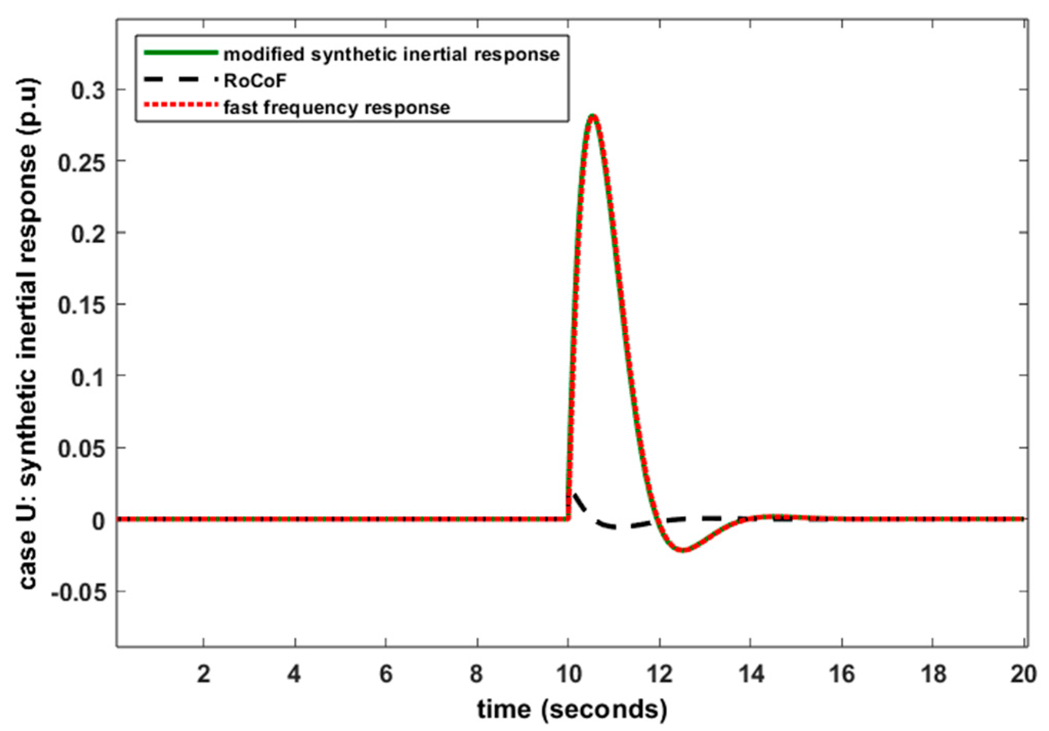
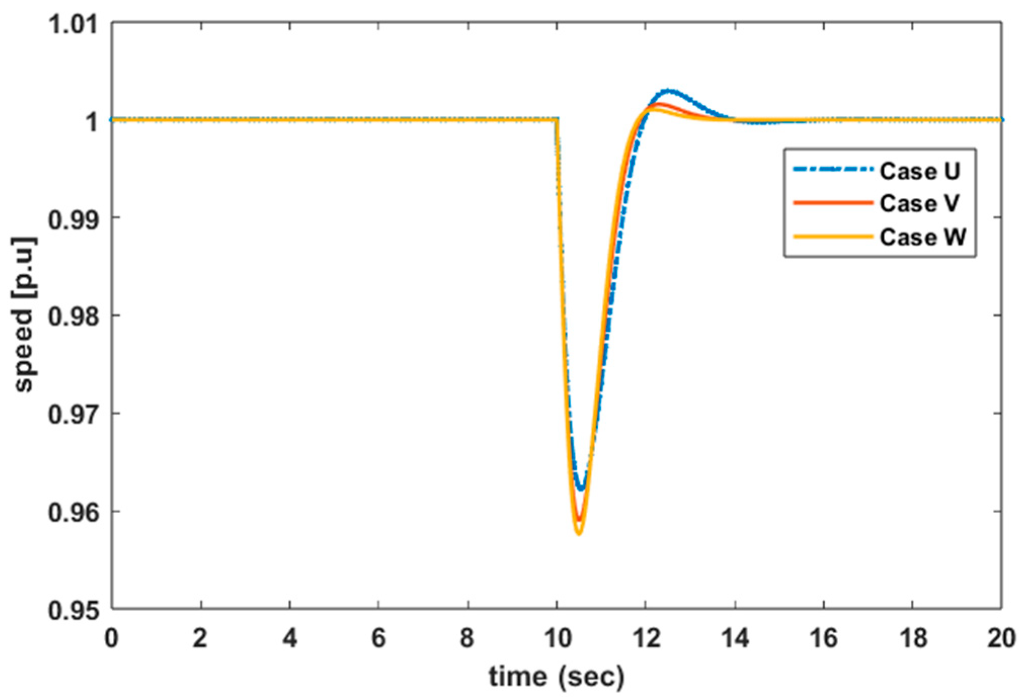
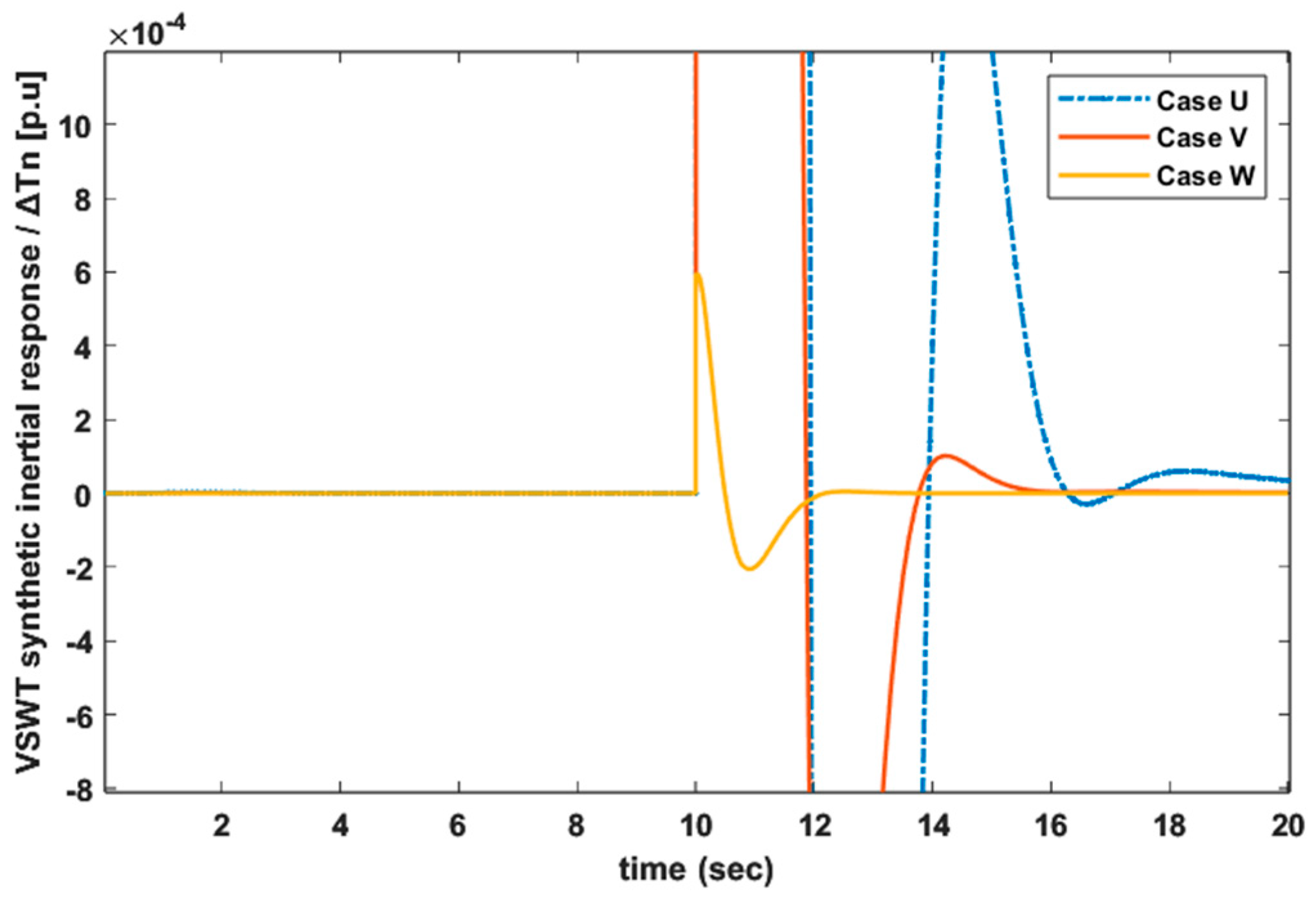
6.3. Case U: FR Provided by VSWT Using Modified Synthetic Inertial Control

To release the hidden inertia or synthetic inertia in VSWT, new proposed controls named as modified synthetic inertial control, discussed above, are introduced in VSWT. In this case, the behavior of VSWT with optimized DPP (Case T) for FR is discussed. However, the new control loops in VSWT are optimally tuned using the SPBA methodology while the DPP parameters remain the same as in Case T. Thus, a testing series of different proposed control gain parameter (Kdn and Kpn) combinations was based on the controller quality index, Q. The new optimized values of Kdn and Kpn are 0.15 and 7.45, respectively. In this way, both power plants of the San Cristobal hybrid WDPS are optimally tuned, individually. To check the system performance, the authors again consider a perturbation of a 0.5 p.u. step response as Pload against a constant wind speed, 9.2966 ms−1. The WDPS FD response against such a perturbation is shown in Figure 10, which is improved by 0.49% (0.32 Hz) and 9.58% (4.62 Hz) when compared with Case T and the base case, respectively. Similarly, the synthetic inertia (approx. 0.29 p.u.) released by VSWT is shown in Figure 10. This synthetic inertia enables VSWT to contribute to the PFR during transient periods. Figure 10 shows in detail the contribution of the modified synthetic inertial control. It clearly justifies that VWST provide a fast frequency response and significantly contribute against the RoCoF.

6.4. Case V: FR Provided by VSWT Using Proportional Control

In this case, only proportional control is introduced in VSWT to release synthetic inertia. In other words, the authors split the modified synthetic inertial control into two different individual control loops (discussed in Case V and Case W) to highlight the distinct inertial impact. Therefore, VSWT with proportional control are tuned using the proposed tuning methodology, while the DPP remains the same as in Case T. Thus, the SBPA methodology illustrates better optimized results for VSWT against Kpn = 1.92. Against a 0.5 p.u. increase in load demand, the WDPS shows a NADIR = 0.9591 p.u. (47.96 Hz), as shown in Figure 11. Figure 11 clearly reflects that the hybrid WDPS with proposed proportional control follows nearly the same trend as discussed in Case U. However, the FD is 0.0047 p.u. more as compared to Case U. Irrespective of such FD behavior, the authors conclude that proportional control (droop control) is a good alternative for modified synthetic inertial control. Because such a difference of 0.0047 p.u. is negligible against a rare event, 0.5 p.u. load demand increment. As the load demand increment is reduced further, such a difference also moves toward zero. However, such research findings indicate that VSWT can provide enough inertia with an advantage of robustness in terms of eliminating derivatives in modified synthetic inertial control. Furthermore, the controller quality index in Table A1 justifies the above-mentioned claim. Irrespective of FD, the controller quality index of Case V is better than that of Case U because of a smaller number of sign changes in frequency deviation.

6.5. Case W: FR Provided by VSWT Using Inertial Control

This case helps to compare the VSWT performance against the droop and modified synthetic inertial controls. In this case, VSWT hidden inertia is released by using only inertial control (Kdn). However, the DPP parameters remain unchanged (Case T). Again, the authors tuned VSWT using the SBPA optimization technique. Therefore, the best unique gain parameter for inertial control that shows the minimum FD, ISE and IAE is 0.004. To simulate such a hybrid WDPS against 0.5 p.u. Pload, FD is equal to 0.9576 p.u. (47.88 Hz). Such a response is 0.16% and 0.49% worse than Case V and Case U, respectively. However, it is 9.14% better than the base case. It is concluded that VSWT perform better the in case of modified synthetic inertial control. Thus, the priorities to adopt a proposed control for synthetic inertia are Case U > Case V > Case W.
It is important to discuss that the hybrid power system behavior is nearly the same as in Case T. The authors further conclude that inertial control does not significantly contribute to the release in synthetic inertia in the hybrid model if the DPP is optimally tuned. This is because the major contribution for inertial support is provided by the DPP. Furthermore, comparing both Cases U and V with Case T, it is observed that Case U and Case V are 0.49% and 0.16% more efficient. The VSWT synthetic inertial contribution in Case W is shown in Figure 12 and Figure 13. Figure 13 is a zoom-in near the perturbation.

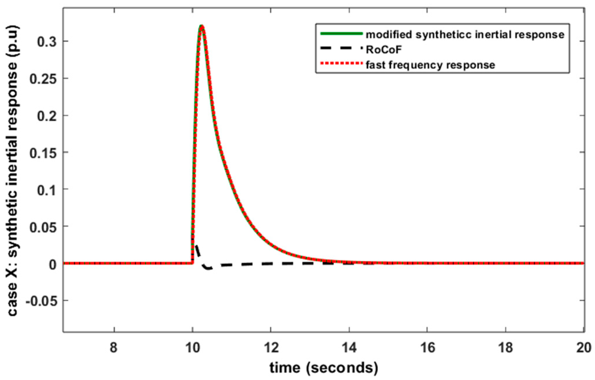
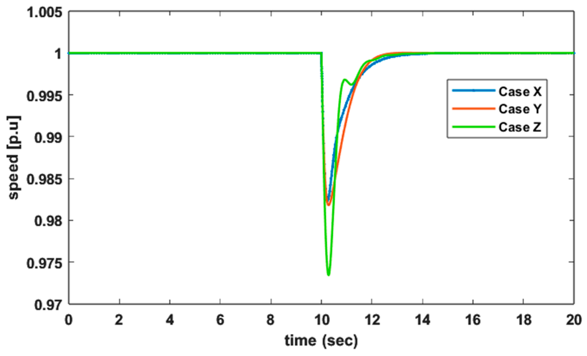
6.6. Case X: Simultaneously Tuned: DPP and VSWT with Modified Synthetic Inertial Control

In this case, both power plants of San Cristobal Island, i.e., the wind power plant including proposed controls (Figure 6) and the DPP are considered simultaneously. The SPBA optimization methodology is used to tune the controller parameters of the proposed controls and diesel governor (Kp_d and Ki_d) against the step response (0.5 p.u.). After comparing thousands of controllers’ gain combinations, the SPBA methodology shows a better result against the parameters Kp_d = 30.76, Kp_i = 32.76, Kdn = 0.26 and Kpn = 18.18. Moreover, NADIR, ISE and IAE are 5.62 Hz (11.43%), 0.040 and 0.4651, better than the base case. The synthetic inertial support provided by VSWT is shown in Figure 14, Figure 15 and Figure 16. Figure 14 expresses the detailed contribution of both controls, i.e., Kdn (RoCoF) and Kpn (fast frequency response). Furthermore, it is concluded that the hybrid WDPS performs better in this case (Case X) compared to all above-mentioned cases in terms of low FD, ISE and IAE. In other words, when all hybrid power plant controllers are optimally tuned simultaneously, then its performance increases significantly irrespective of individual optimization. Thus, Case X is 2.52%, 2.04%, 2.36% and 2.52% more efficient (in providing FR) than Case T, Case U, Case V and Case W, respectively.

6.7. Case Y: Simultaneously Tuned: DPP and VSWT with Droop Control

Case Y is similar to Case X in terms of being simultaneously optimally tuned in both power plants. However, synthetic inertia is provided by only proportional control while Kdn remains zero. Figure 16 clearly shows that VSWT contributes to inertial support when a step response of 0.5 p.u. is applied as a perturbation in load demand. Furthermore, NADIR is reduced by 11.38% (5.59 Hz) when compared with the base case. It is important to mentioned that the hidden inertia released by VSWT is nearly the same in both cases: Case X and Case Y. This is the same observation as in Case U and Case V. The results again validate that droop control is a good replacement for modified synthetic inertial control. However, the FR support provided by droop control is 0.06% less than in Case X. Therefore, droop control has significance in terms of robustness because no differentiation of frequency is needed. Furthermore, the controller quality index in Table A1 justifies the above-mentioned claim.

6.8. Case Z: Simultaneously Tuned: DPP and VSWT with Traditional Inertial Control

In this case, both power plants of San Cristobal Island undergo SBPA optimization control while Kpn remains zero in modified synthetic inertial control. Only traditional inertial control enables VSWT to release inertia against the applied perturbation of a 0.5 p.u. step response. Figure 15 shows the FD behaviour against such a perturbation. It is clear that VSWT with traditional inertial control not only reduced the FD but also ISE and IAE as compared to the base case. However, the system performance is not as good compared with Case X and Case Y. Case X is 0.92% better than Case Z while Case Y is 0.86% better in terms of FR. When comparing all these three cases, it is concluded that Case X > Case Y > Case Z > base case.

7. Controller Performance Evaluation

To evaluate and justify the performance of the proposed controllers, perturbations (step, ramp and random) whose combination represents any realistic event [45] are considered. Therefore, the loss of a wind generator or an increase in load demand is reflected by the step response. Similarly, the gradual increment in wind speed and wind variations is manifested by the ramp and random response, respectively. Furthermore, to analyze in depth, the authors believe some other rare events can occur in power systems. These events include both load demand and wind variation simultaneously increasing or decreasing. Moreover, the load demand increases while the wind speed decreases and vice versa. To validate the proposed controller and hybrid WDPS performance (as a whole) under such scenarios, the authors consider Case U as a case study. The main reason to adopt such a specific case is due to its better performance when compared to all other seven cases. However, the results of Case V are nearly the same as in Case U. However, the authors choose the best one to evaluate the performance. It is important to mention that the WDPS based on the above-mentioned cases can perform well during contingencies. But the WDPS performance varies case by case. Thus, Figure 17 and Figure 18 show the behavior of various hybrid WDPS variables against the ramp and random response. The results clearly show that the WDPS can work efficiently against the loss of a wind generator (resulting in increased load demand) and wind speed fluctuation. In addition, the BPAC rotation smoothness demonstrates the effect of pitch compensation control (gain parameters given in Table 4). However, the fulfilment of the load demand, Pload = 1.5 p.u., is met by both power plants. Whenever VSWT is below its maximum generated power (1 p.u.), the DPP provides the difference in power (Pload − Pw).
Similarly, Figure 19 shows the hybrid WDPS response against variable load demand and wind variation. Such fluctuating behavior of Vw and Pload covers all different situations: Pload increases while Vw decreases or vice versa. It is important to mention that both power plants of hybrid WDPS have their own limits, i.e., Pw,max and Pd are 1 p.u. It means that the difference between Pw and load demand must not be greater than 1 p.u., because the DPP is responsible for providing such a power difference. Similarly, the BPAC rotation is not instantaneous, and they have their own practical limitations due to servomotor or maximum rotation per second. Therefore, VSWT do not operate beyond the allowable beta angle rotation (2°/s) and cut-out wind speed, which is 25 ms−1 [46] in this case.

8. Conclusions

In this paper, various control loops (modified synthetic inertial control, droop control and traditional inertial control) are proposed for helping VSWT to release hidden inertia and provide FR during contingency conditions. Then, these proposed controls are implemented into the San Cristobal Island hybrid WDPS to find a better FR solution. With this aim, seven different approaches (Cases T, U, V, W, X, Y and Z) based on the above-mentioned proposed controls are discussed in detail to highlight the various benefits and improvements. Furthermore, the SPBA methodology is adopted to optimally tune the proposed approaches. Thus, after exhaustive research, it is concluded that Case X provides better FR and minimizes FD (11.43%), ISE (0.04) and IAE (0.47) as compared to the actual San Cristobal WDPS parameters. Similarly, by comparing all other approaches, it concludes that Case Y > Case Z > Case U > Case V > Case W and Case T. The authors further found that both approaches (X, Y and U, V) provide nearly the same results. Therefore, it is summarized that the best alternative for modified synthetic inertial control is droop control. It is preferred in terms of hybrid power system robustness because it eliminates the need to perform a numerical derivative. Furthermore, it is determined that in hybrid operations both power plants (DPP and WPP) under study must be optimized simultaneously to obtain an optimized performance. If both power plants are individually optimized, then there are no significant improvements in the results. Case U is the best fit to the above-mentioned statement. When comparing Case U with Case T, the FD only improved by 0.49% (0.24 Hz) against a 0.5 p.u. increase in load demand.
To evaluate the hybrid power system under the proposed approach, the hybrid WDPS undergoes several realistic events (increase in Vw, wind fluctuations, both load demand and Vw fluctuate simultaneously). These realistic events validate the results and the hybrid power system performance.

Author Contributions

Conceptualization, J.A.S.-F.; methodology, J.A.S.-F. and M.A.; software, M.A. and J.A.S.-F.; validation, M.A. and J.A.S.-F.; formal analysis, M.A. and J.A.S.-F.; investigation, M.A. and J.A.S.-F.; resources, J.A.S.-F.; data curation, M.A. and J.A.S.-F.; writing—original draft preparation, M.A. and J.A.S.-F.; writing—review and editing, J.A.S.-F.; visualization, M.A. and J.A.S.-F.; supervision, J.A.S.-F.; project administration, J.A.S.-F.; funding acquisition, J.A.S.-F. All authors have read and agreed to the published version of the manuscript.

Funding

This research was funded by Universidad Politécnica de Madrid, grant number RP2304330031.

Data Availability Statement

All the data supporting the reported results can be found in this paper and in the cited references.

Conflicts of Interest

The authors declare no conflicts of interest. The funders had no role in the design of the study; in the collection, analysis, or interpretation of the data; in the writing of the manuscript; or in the decision to publish the results.

Appendix A

Table A1. Detailed experimental measurements of cases: base, T, U, V, W, X, Y, Z.
CaseNADIR (p.u.)ISEIAEQ (p.u.)
Base0.87010.04100.48041.1373 × 103
T0.95760.00120.03911.3665 × 103
U0.96230.00110.04381.6790 × 103
V0.95910.00120.04041.1371 × 103
W0.95760.00120.03911.19224 × 104
X0.98241.5215 × 10−40.01931.5206 × 104
Y0.98182.0568 × 10−40.01691.5658 × 104
Z0.97342.5728 × 10−40.01613.554 × 103
Figure A1. Flow chart of the SPBA optimization algorithm.
Electronics 13 00852 g0a1

References

  1. Asad, M. Improving Power Flow Using Static Synchronous Series Compensator. Egypt. J. Eng. Sci. Technol. 2021, 33, 69–74. [Google Scholar] [CrossRef]
  2. Li, Z.; Zhou, S.; Yang, Z. Recent Progress on Flutter-based Wind Energy Harvesting. Int. J. Mech. Syst. Dyn. 2022, 2, 82–98. [Google Scholar] [CrossRef]
  3. Fernández-Guillamón, A.; Muljadi, E.; Molina-García, A. Frequency Control Studies: A Review of Power System, Conventional and Renewable Generation Unit Modeling. Electr. Power Syst. Res. 2022, 211, 108191. [Google Scholar] [CrossRef]
  4. Fernández-Guillamón, A.; Martínez-Lucas, G.; Molina-García, Á.; Sarasua, J.I. An Adaptive Control Scheme for Variable Speed Wind Turbines Providing Frequency Regulation in Isolated Power Systems with Thermal Generation. Energies 2020, 13, 3369. [Google Scholar] [CrossRef]
  5. ENTSO-E. Electricity Balancing in Europe. Available online: https://docstore.entsoe.eu/ (accessed on 10 December 2023).
  6. Ochoa, D.; Martinez, S. Proposals for Enhancing Frequency Control in Weak and Isolated Power Systems: Application to the Wind-Diesel Power System of San Cristobal Island-Ecuador. Energies 2018, 11, 910. [Google Scholar] [CrossRef]
  7. Albadi, M.H.; El-Saadany, E.F. Overview of Wind Power Intermittency Impacts on Power Systems. Electr. Power Syst. Res. 2010, 80, 627–632. [Google Scholar] [CrossRef]
  8. Martínez-Lucas, G.; Sarasúa, J.; Sánchez-Fernández, J. Frequency Regulation of a Hybrid Wind–Hydro Power Plant in an Isolated Power System. Energies 2018, 11, 239. [Google Scholar] [CrossRef]
  9. Lazarewicz, M.L.; Ryan, T.M. Integration of Flywheel-Based Energy Storage for Frequency Regulation in Deregulated Markets. In Proceedings of the PES 2010 IEEE PES General Meeting, Minneapolis, MN, USA, 25–29 July 2010. [Google Scholar]
  10. Liu, L.; Senjyu, T.; Kato, T.; Mandal, P.; Hemeida, A.M.; Howlader, A.M. Renewable Energy Power System Frequency Control by Using PID Controller and Genetic Algorithm. In Proceedings of the 2020 12th IEEE PES Asia-Pacific Power and Energy Engineering Conference (APPEEC), Nanjing, China, 20–23 September 2020; pp. 1–5. [Google Scholar]
  11. Guha, D.; Roy, P.K.; Banerjee, S. Frequency Control of a Wind-Diesel-Generator Hybrid System with Squirrel Search Algorithm Tuned Robust Cascade Fractional Order Controller Having Disturbance Observer Integrated. Electr. Power Compon. Syst. 2022, 50, 814–839. [Google Scholar] [CrossRef]
  12. Afzal Thoker, Z.; Ahmad Lone, S. Dynamic Performance Improvement of Wind-Diesel Power System through Robust Sliding Mode Control of Hybrid Energy Storage System. Wind Eng. 2022, 46, 1065–1079. [Google Scholar] [CrossRef]
  13. Mi, Y.; Chen, B.; Cai, P.; He, X.; Liu, R.; Yang, X. Frequency Control of a Wind-Diesel System Based on Hybrid Energy Storage. Prot. Control Mod. Power Syst. 2022, 7, 31. [Google Scholar] [CrossRef]
  14. Panwar, A.; Sharma, G.; Bansal, R.C. Optimal AGC Design for a Hybrid Power System Using Hybrid Bacteria Foraging Optimization Algorithm. Electr. Power Compon. Syst. 2019, 47, 955–965. [Google Scholar] [CrossRef]
  15. Kumar, N.K.; Gopi, R.S.; Kuppusamy, R.; Nikolovski, S.; Teekaraman, Y.; Vairavasundaram, I.; Venkateswarulu, S. Fuzzy Logic-Based Load Frequency Control in an Island Hybrid Power System Model Using Artificial Bee Colony Optimization. Energies 2022, 15, 2199. [Google Scholar] [CrossRef]
  16. Fox, B.; Flynn, D.; Bryans, L.; Jenkins, N.; Milborrow, D.; O’Malley, M.; Watson, R.; Anaya-Lara, O. Wind Power Integration: Connection and System Operational Aspects; Institution of Engineering and Technology: Stevenage, UK, 2007; ISBN 9780863414497. [Google Scholar]
  17. Abad, G.; López, J.; Rodríguez, M.A.; Marroyo, L.; Iwanski, G. Doubly Fed Induction Machine: Modeling and Control for Wind Energy Generation; John Wiley & Sons, Inc.: Hoboken, NJ, USA, 2011; ISBN 9781118104965. [Google Scholar]
  18. Ackermann, T. Wind Power in Power Systems; Ackermann, T., Ed.; Wiley: Hoboken, NJ, USA, 2012; ISBN 9780470974162. [Google Scholar]
  19. Cai, T.; Liu, S.; Yan, G.; Liu, H. Analysis of Doubly Fed Induction Generators Participating in Continuous Frequency Regulation with Different Wind Speeds Considering Regulation Power Constraints. Energies 2019, 12, 635. [Google Scholar] [CrossRef]
  20. Serrano-González, J.; Lacal-Arántegui, R. Technological Evolution of Onshore Wind Turbines—A Market-based Analysis. Wind Energy 2016, 19, 2171–2187. [Google Scholar] [CrossRef]
  21. Vázquez-Hernández, C.; Serrano-González, J.; Centeno, G. A Market-Based Analysis on the Main Characteristics of Gearboxes Used in Onshore Wind Turbines. Energies 2017, 10, 1686. [Google Scholar] [CrossRef]
  22. Quan, Y.; Hang, L.; He, Y.; Zhang, Y. Multi-Resonant-Based Sliding Mode Control of DFIG-Based Wind System under Unbalanced and Harmonic Network Conditions. Appl. Sci. 2019, 9, 1124. [Google Scholar] [CrossRef]
  23. Liserre, M.; Cardenas, R.; Molinas, M.; Rodriguez, J. Overview of Multi-MW Wind Turbines and Wind Parks. IEEE Trans. Ind. Electron. 2011, 58, 1081–1095. [Google Scholar] [CrossRef]
  24. Shen, Y.-W.; Ke, D.-P.; Sun, Y.-Z.; Kirschen, D.S.; Qiao, W.; Deng, X.-T. Advanced Auxiliary Control of an Energy Storage Device for Transient Voltage Support of a Doubly Fed Induction Generator. IEEE Trans. Sustain. Energy 2016, 7, 63–76. [Google Scholar] [CrossRef]
  25. Molina-Garcia, A.; Fernandez-Guillamon, A.; Gomez-Lazaro, E.; Honrubia-Escribano, A.; Bueso, M.C. Vertical Wind Profile Characterization and Identification of Patterns Based on a Shape Clustering Algorithm. IEEE Access 2019, 7, 30890–30904. [Google Scholar] [CrossRef]
  26. Alsharafi, A.; Besheer, A.; Emara, H. Primary Frequency Response Enhancement for Future Low Inertia Power Systems Using Hybrid Control Technique. Energies 2018, 11, 699. [Google Scholar] [CrossRef]
  27. Fernández-Guillamón, A.; Gómez-Lázaro, E.; Muljadi, E.; Molina-García, Á. Power Systems with High Renewable Energy Sources: A Review of Inertia and Frequency Control Strategies over Time. Renew. Sustain. Energy Rev. 2019, 115, 109369. [Google Scholar] [CrossRef]
  28. Fang, X.; Krishnan, V.; Hodge, B.-M. Strategic Offering for Wind Power Producers Considering Energy and Flexible Ramping Products. Energies 2018, 11, 1239. [Google Scholar] [CrossRef]
  29. Gonzalez-Longatt, F.M.; Bonfiglio, A.; Procopio, R.; Verduci, B. Evaluation of Inertial Response Controllers for Full-Rated Power Converter Wind Turbine (Type 4). In Proceedings of the 2016 IEEE Power and Energy Society General Meeting (PESGM), Boston, MA, USA, 17–21 July 2016; pp. 1–5. [Google Scholar]
  30. Renuka, T.K.; Reji, P. Frequency Control of Wind Penetrated Hydro-Dominated Power System. In Proceedings of the 2015 International Conference on Technological Advancements in Power and Energy (TAP Energy), Kollam, India, 24–26 June 2015; pp. 316–321. [Google Scholar]
  31. Morren, J.; Pierik, J.; de Haan, S.W.H. Inertial Response of Variable Speed Wind Turbines. Electr. Power Syst. Res. 2006, 76, 980–987. [Google Scholar] [CrossRef]
  32. Ramtharan, G.; Jenkins, N.; Ekanayake, J.B. Frequency Support from Doubly Fed Induction Generator Wind Turbines. IET Renew. Power Gener. 2007, 1, 3. [Google Scholar] [CrossRef]
  33. Fu, Y.; Zhang, X.; Hei, Y.; Wang, H. Active Participation of Variable Speed Wind Turbine in Inertial and Primary Frequency Regulations. Electr. Power Syst. Res. 2017, 147, 174–184. [Google Scholar] [CrossRef]
  34. Ekanayake, J.; Jenkins, N. Comparison of the Response of Doubly Fed and Fixed-Speed Induction Generator Wind Turbines to Changes in Network Frequency. IEEE Trans. Energy Convers. 2004, 19, 800–802. [Google Scholar] [CrossRef]
  35. Gonzalez-Longatt, F.; Chikuni, E.; Stemmet, W.; Folly, K. Effects of the Synthetic Inertia from Wind Power on the Total System Inertia after a Frequency Disturbance. In Proceedings of the IEEE Power and Energy Society Conference and Exposition in Africa: Intelligent Grid Integration of Renewable Energy Resources (PowerAfrica), Johannesburg, South Africa, 9–13 July 2012; pp. 1–7. [Google Scholar]
  36. Bonfiglio, A.; Invernizzi, M.; Labella, A.; Procopio, R. Design and Implementation of a Variable Synthetic Inertia Controller for Wind Turbine Generators. IEEE Trans. Power Syst. 2019, 34, 754–764. [Google Scholar] [CrossRef]
  37. Morren, J.; de Haan, S.W.H.; Kling, W.L.; Ferreira, J.A. Wind Turbines Emulating Inertia and Supporting Primary Frequency Control. IEEE Trans. Power Syst. 2006, 21, 433–434. [Google Scholar] [CrossRef]
  38. Mauricio, J.M.; Marano, A.; Gomez-Exposito, A.; Martinez Ramos, J.L. Frequency Regulation Contribution Through Variable-Speed Wind Energy Conversion Systems. IEEE Trans. Power Syst. 2009, 24, 173–180. [Google Scholar] [CrossRef]
  39. Díaz-González, F.; Hau, M.; Sumper, A.; Gomis-Bellmunt, O. Participation of Wind Power Plants in System Frequency Control: Review of Grid Code Requirements and Control Methods. Renew. Sustain. Energy Rev. 2014, 34, 551–564. [Google Scholar] [CrossRef]
  40. Dreidy, M.; Mokhlis, H.; Mekhilef, S. Inertia Response and Frequency Control Techniques for Renewable Energy Sources: A Review. Renew. Sustain. Energy Rev. 2017, 69, 144–155. [Google Scholar] [CrossRef]
  41. Singarao, V.Y.; Rao, V.S. Frequency Responsive Services by Wind Generation Resources in United States. Renew. Sustain. Energy Rev. 2016, 55, 1097–1108. [Google Scholar] [CrossRef]
  42. Xu, L.; Yao, L.; Sasse, C. Grid Integration of Large DFIG-Based Wind Farms Using VSC Transmission. IEEE Trans. Power Syst. 2007, 22, 976–984. [Google Scholar] [CrossRef]
  43. Asad, M.; Martinez, S.; Sanchez-Fernandez, J.A. Diesel Governor Tuning for Isolated Hybrid Power Systems. Electronics 2023, 12, 2487. [Google Scholar] [CrossRef]
  44. Martínez-Lucas, G.; Sarasúa, J.I.; Sánchez-Fernández, J.Á. Eigen Analysis of Wind–Hydro Joint Frequency Regulation in an Isolated Power System. Int. J. Electr. Power Energy Syst. 2018, 103, 511–524. [Google Scholar] [CrossRef]
  45. Jones, D.I.; Mansoor, S.P.; Aris, F.C.; Jones, G.R.; Bradley, D.A.; King, D.J. A Standard Method for Specifying the Response of Hydroelectric Plant in Frequency-Control Mode. Electr. Power Syst. Res. 2004, 68, 19–32. [Google Scholar] [CrossRef]
  46. GE Energy. 1.5 MW Wind Turbine. Available online: https://geosci.uchicago.edu/~moyer/GEOS24705/Readings/GEA14954C15-MW-Broch.pdf (accessed on 10 January 2024).
Figure 1. Flow chart of VSWT’s frequency control strategies.
Electronics 13 00852 g001
Figure 2. General schematic diagram of VSWT.
Electronics 13 00852 g002
Figure 3. MATLAB Simulink representation of the generator and electronics converter.
Electronics 13 00852 g003
Figure 4. MATLAB Simulink representation of BPAC.
Electronics 13 00852 g004
Figure 5. General schematic of the CAT-3512DITA diesel governor.
Electronics 13 00852 g005
Figure 6. Proposed modified synthetic inertial control of VSWT to release hidden inertia.
Electronics 13 00852 g006
Figure 7. Modified BPAC of VSWT.
Electronics 13 00852 g007
Figure 8. Base case: San Cristobal Island WDPS against the loss of a wind generator (Pload increment 0.5 p.u.).
Electronics 13 00852 g008
Figure 9. WDPS behavior in Case T against Pload = 0.5 p.u.
Electronics 13 00852 g009
Figure 10. Detailed synthetic inertial response of VSWT in Case U.
Electronics 13 00852 g010
Figure 11. VSWT FD response against a 0.5 p.u. step response in Case U, V and W.
Electronics 13 00852 g011
Figure 12. VSWT synthetic inertial response in Case U, V and W.
Electronics 13 00852 g012
Figure 13. VSWT synthetic inertial response in Case W, zooming in.
Electronics 13 00852 g013
Figure 14. Detailed synthetic inertial behavior of VSWT in Case X.
Electronics 13 00852 g014
Figure 15. VSWT FD response against increased in Pload (0.5 p.u.) in Case X, Y and Z.
Electronics 13 00852 g015
Figure 16. VSWT synthetic inertial response in Case X, Y and Z.
Electronics 13 00852 g016
Figure 17. WDPS response against a gradually increase in Vw.
Electronics 13 00852 g017
Figure 18. WDPS response against wind fluctuation.
Electronics 13 00852 g018
Figure 19. WDPS behavior against a simultaneously increase in Pload and Vw.
Electronics 13 00852 g019
Table 1. Dataset of DPS installed at San Cristobal Island [43].
SymbolParametersValues
Model of diesel engineCAT-3512 DITA
fFrequency60 Hz
SCapacity813 KVA
HTConstant of inertia0.4208 s
NsSynchronous speed1200 RPM
PratedRated power650 kW
VoutOutput voltage480 V ± 5%
Tmax/TminTorque max/min 1.1 p.u./0 p.u.
t1/t2/t3Time constants0.024 s/0.1 s/0.01 s
Table 2. San Cristobal Island WT parameters [6].
SymbolsParametersValues
PbaseBase power800 kW
PgGenerator power min/max0.04 p.u./1 p.u.
dβ/dt, min/maxRate of pitch angle min/max−2°/s/+2°/s
KoptOptimization constant0.6728
DDiameter of the VSWT rotor59 m
fnomNominal frequency of the generator50 Hz
HiConstant of inertia4.18
Kppc/KipcGains of the PI pitch controller150/25
ωmin, ω0, ω1, ωmaxSpeed limits of MPPT0.5 p.u., 0.51 p.u., 1.09 p.u., 1.1 p.u.
n1, n2, n3, n4, n5, n6Constants of MPPT curve0.5176, 116, 0.4, 5, 21, 0.0068
τpServo-motor time constant0.3 s
ΡAir density1.225 kgm−3
τcTime constant of the generator and electronics convertor20 ms
g,baseBase speed of the generator157.08 rad/s
t,baseTurbine base speed2.3 rad/s
Vw,nomNominal wind speed10 ms−1
Kpsc/KiscGain parameters of the speed controller min/max0.3/8
Tem,min/maxElectromagnetic torque min/max0.08 p.u./0.91 p.u.
Table 3. San Cristobal Island WDPS tuned parameters using SPBA.
CaseDiesel Governor Controller Gain ParametersModified Synthetic Inertial Control
Kp_dKi_dKdnKpn
Base 2.2941.45800
T10.1313.3500
U10.1313.350.157.45
V10.1313.3501.92
W10.1313.350.0040
X30.7632.760.2618.18
Y24.6529.55023.43
Z23310.020
Table 4. Several tuned parameters of WT.
CaseParametersValues
Kpc/KicPitch compensation controller parameters0/150
Kppc/KipcBlade pitch controller gain parameters1300/150
Disclaimer/Publisher’s Note: The statements, opinions and data contained in all publications are solely those of the individual author(s) and contributor(s) and not of MDPI and/or the editor(s). MDPI and/or the editor(s) disclaim responsibility for any injury to people or property resulting from any ideas, methods, instructions or products referred to in the content.

