Abstract
Three-phase voltage PWM rectifier is a multivariable, strong coupling, nonlinear multi-input and multi-output system. In the design of rectifier control systems, with PI control it is difficult to achieve the ideal control effect, the dynamic performance is poor, and the parameter computation is complex. Moreover, the traditional sliding mode control voltage outer loop suffers from the problem of chattering, which is difficult to solve. Responding to the above issues, a new type of variable speed reaching law is proposed, which is applied to the voltage outer loop sliding mode control, while the feedback linearization principle is introduced to the current inner loop, and a new type of double closed-loop sliding mode control system is obtained by applying the two theories to the design of the sliding mode controller. A simulation model is established in MATLAB/Simulink to compare the PI control, the SMC control and the V-SMC control strategy proposed in this paper (voltage outer loop V-SMC current inner loop FLC-SMC control), and the simulation results show that the rectifier under the new dual-closed-loop sliding mode control strategy has the advantages of good dynamic performance, strong robustness and strong anti-interference ability. At the same time, compared with the traditional sliding mode control strategy, the vibration suppression effect under the proposed control strategy is obvious. Finally, a 10 kW rectifier control system is built on a semi-physical hardware-in-the-loop experimental platform to further verify the correctness and superiority of the proposed control strategy.
1. Introduction
With the increasing depletion of global fossil energy and the intensification of environmental pollution problems, the effective utilization of clean, renewable ocean energy has become a strategic choice for the world’s major coastal countries [1], and the International Energy Agency predicts that the global supply of renewable energy will reach more than 50% in 2035 [2]. At the same time, the development and utilization of marine energy is of great significance to the power supply of coastal areas, offshore islands and offshore reefs, and is the strategic frontier to protect national security and safeguard marine rights and interests [3]. As a kind of marine energy that has been re-emphasized and developed in recent decades, ocean current energy has the characteristics of strong regularity, predictability, energy stability and high energy density [4]. The flow rate range of seawater that can effectively generate electricity is 0.6–3.5 m/s, the rated flow rate is generally 2 m/s, the grid-connected flow rate is 1 m/s and the cut-out flow rate is 3 m/s [5,6,7]. Ocean current energy has a relatively fixed law of change, but depending on the season, the topography of the channel and climate and other factors, the actual seawater flow rate will fluctuate within a certain range. The generator in ocean current energy generation adopts a permanent magnet structure; permanent magnet excitation cannot be adjusted; output voltage and frequency are positively correlated with speed; therefore, the power generated has a wide output characteristic. The three-phase uncontrolled rectifier series DC/DC converter is mostly used in ocean current energy generation to transform the power issued by the front stage into the DC bus; this uncontrolled rectifier injects harmonics into the machine side, which leads to internal heating and loss in the generator, reduces the power generation efficiency and decreases the generator’s service life. The three-phase PWM rectifier has the characteristics of high power factor, small current harmonic distortion on the AC side and adjustable output voltage on the DC side [8], which is more suitable for application in ocean current energy generation. This kind of rectifier is usually controlled via the traditional PI control strategy, which is characterized by cumbersome parameter calculations and poor dynamic performance under complex operating conditions [9]. The three-phase PWM rectifier is a multivariable, strongly coupled, nonlinear multi-input and multi-output system. The traditional linear control method is not applicable to the rectifier system. In order to improve the control effect of the rectifier, scholars have proposed a lot of control methods, and sliding mode control is one of the most important ones, which has the characteristics of fast dynamic response speed and strong anti-interference ability.
Aiming at the nonlinear, multivariable and strong coupling characteristics of the rectifier, reference [10] designed a sliding mode controller with selectable functions in the current inner loop, and analyzed the principle of sliding mode control, but did not solve the problem of jitter vibration in the control process. Reference [11] designed a dual-closed-loop all sliding mode controller scheme, while using the exponential reaching law to reduce the jitter; the dynamic performance and robustness were significantly improved and enhanced. Reference [12] proposed a higher-order sliding mode control scheme combining the integral sliding mode surface and the end-sliding mode surface; at the same time, the authors proposed a higher-order sliding mode reaching law, which effectively reduces the jitter phenomenon of the sliding mode surface, and it has great engineering application value, but the amount of calculation is large. Reference [13] proposed a control scheme that combines a sliding mode observer and a sliding mode control strategy to enhance the anti-interference capability of the rectifier’s DC-side voltage as well as the stability of the grid-side current operation, so as to enable it to operate normally under a variety of complex operating conditions. Reference [14] proposed a sliding mode control scheme incorporating a linear expansion observer to further enhance the stable operation of the DC voltage. Reference [15] proposed a method to suppress DC bus voltage doubling frequency pulsations under grid voltage unbalance by using a fractional-order sliding mode control strategy for DC-side bus voltage to solve the problem of negative sequence components of AC currents which results in DC bus voltage doubling frequency pulsations in grid-connected AC–DC hybrid microgrids with AC-side voltage unbalance. Reference [16] proposed a model predictive sliding mode control scheme and designed an optimized model predictive control algorithm, which further improves the steady-state performance of the system by reducing the number of algorithmic optimization searches. References [17,18,19,20] propose more improvement schemes for sliding mode control strategies.
The improved control strategy of the three-phase voltage PWM rectifier proposed in this paper is applied to ocean current energy generation, so it is more important to ensure that it can operate safely and stably, which puts forward higher requirements on the performance of the rectifier. In this paper, a new variable speed reaching law (Variable Speed Reaching Law, VSRL) design scheme is proposed, the voltage outer loop sliding mode controller based on the new variable speed reaching law is designed (VSRL-SMC), the feedback linearization control (Feedback Linearization Control, FLC) method for nonlinear systems in the inner loop is introduced, and FLC is combined with sliding mode control (Sliding Mode Control, SMC) to form the current inner-loop feedback linearization sliding mode controller (FLC-SMC), which ultimately realizes the voltage-current double-closed-loop sliding mode control system. Finally, MATLAB/Simulink simulation experiments are carried out to compare the control effects of PI control, SMC control and the V-SMC control strategy proposed in this paper (voltage outer loop V-SMC current inner loop FLC-SMC control); at the same time, the control system of a 10 kW rectifier is built to carry out semi-physical simulation experiments, which verifies the superiority and feasibility of the control strategy proposed in this paper.
2. Mathematical Model of Three-Phase Voltage PWM Rectifier
Figure 1 shows the circuit structure of a three-phase voltage PWM rectifier. ek is the three-phase AC-side input voltage; uk is the AC-side voltage after filtering; uNo is the neutral point to the ground voltage value, usually 0. ik is the three-phase AC-side input current; R is the sum of the equivalent resistance of the filtering inductor and the equivalent resistance of the power switching tubes; L is the filtering inductor; C is the DC-side capacitance; RL is the DC-side load resistor; idc is the load current; udc is the DC-side voltage; T1–T6 are the six power switching tubes, each of which is connected in parallel with freewheeling diodes D1–D6; the N-point is the DC bus reference point. At the same time, the saturation of the inductor L on the AC side is not considered; the power switching tubes are all ideal devices; harmonics caused by switching on and off are ignored, and so on.
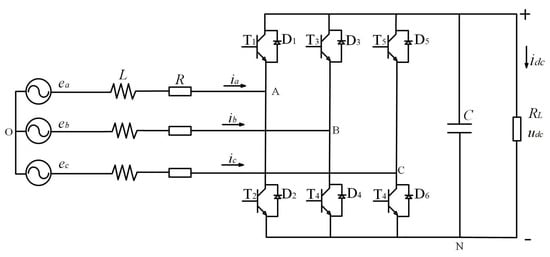
Figure 1.
Three-phase voltage PWM rectifier circuit structure.
Define as the bridge arm switching state:
Assuming that the input voltage on the AC side is a three-phase symmetrical sinusoidal signal with a phase difference of 120°, based on the circuit structure in Figure 1, the mathematical model of the three-phase voltage PWM rectifier in the three-phase stationary coordinate system can be obtained as:
The mathematical model in the two-phase rotating coordinate system is obtained after Clark and Park transformations as:
We found that the dq axes are coupled to each other, which adds difficulty to the design of our controller; also, with switching functions sd and sq as control variables, it is a nonlinear control system; the inductance value L changes with disturbances, heat generation, aging, etc., which affects the control system.
3. Sliding Mode Control Strategy for Three-Phase Voltage PWM Rectifier
Based on the analysis of the previous section, we propose an improved control strategy using sliding mode control for both the voltage outer loop and the current inner loop. Sliding mode control has become a common method for designing robust nonlinear control systems because of its insensitivity to system parameters and disturbances, applicability to nonlinear control systems and fast dynamic response.
The main disadvantage of sliding mode control is the jitter problem, which is undesirable in most applications, and in general the trade-off between jitter suppression and arrival time at the sliding mode surface must be considered. In this paper, a novel Variable Speed Reaching Law (VSRL) design is proposed to reduce the jitter. The voltage outer loop is based on the VSRL to complete the design of the VSRL-SMC voltage outer loop sliding mode controller, and the current inner loop is based on the FLC to complete the design of the FLC-SMC current inner loop sliding mode controller (hereinafter referred to as V-SMC).
3.1. Voltage Outer Loop Sliding Mode Controller with V-SMC Control Strategy
3.1.1. Traditional SMC Design
In general, the motion of the sliding mode variable structure control system consists of two parts, as shown in Figure 2. Segment AB in the figure is the motion before reaching the sliding mold surface, which is a state converging to the sliding mold surface and is called converging mode; segment BC is the motion near the sliding mold surface, which passes through the sliding mold surface a finite number of times and is called sliding mode.
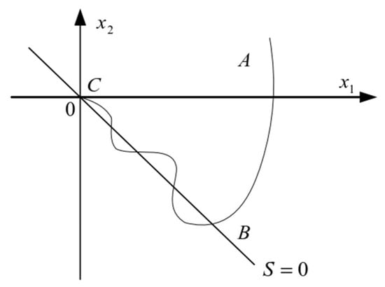
Figure 2.
Two motion phases of the sliding mold control system.
The design objective of the voltage outer loop controller is to make the DC-side voltage udc follow the given reference voltage and keep it stable, and have a strong anti-interference ability. According to the mathematical model of the rectifier derived in the previous section, the error between the commanded value and the actual detected value of the DC voltage can be selected as the state variable in this paper:
From the above equation, with being a constant, we have:
Combining Equations (3) and (5), we have:
The exponential reaching law is chosen as the reaching law for SMC:
s is the state error variable, ε is the amplitude of the switching function and k is the coefficient of the exponential reaching term. The values of ε and k determine the quality of the sliding mode controller.
This is obtained by combining Equations (6) and (7):
It is clear from the previous content that sd and sq are nonlinear switching functions that are not easy to control. When the system is in steady-state condition, iq = 0, eq = 0, , , , and . Bringing the above conditions into Equation (3), we obtain:
The following can be obtained by bringing Equation (9) into Equation (8):
From Equation (10), it can be seen that the voltage outer loop sliding mode controller no longer depends on the nonlinear switching functions sd and sq, and at steady state, the output command current of the voltage outer loop can be obtained as the sliding mode control strategy based on the exponential reaching rate of the voltage outer loop controller:
In accordance with Equation (11), the block diagram of voltage outer loop sliding mode control based on the exponential reaching law is shown in Figure 3. The output result is used as the command current at the input of the current controller.
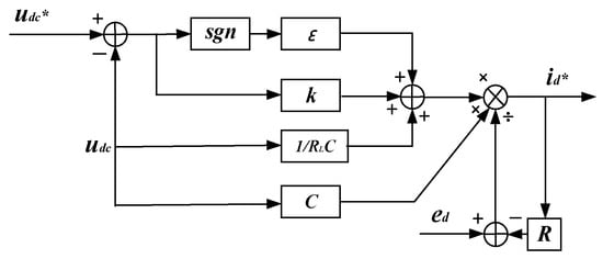
Figure 3.
Block diagram of voltage outer loop sliding mode control based on exponential reaching law.
3.1.2. Analysis of Variable Exponential Convergence Laws and General Exponential Convergence Rates
In the previous section, a sliding mode control method based on the exponential reaching law was introduced to reduce the jitter amplitude via the design of the reaching rate, but the dynamic performance of this traditional sliding mode control is still a bit far from the ideal state. In order to analyze the causes of chattering and propose a solution, the exponential reaching law is rewritten into a discrete form with:
Assuming that the state point of the system only moves from the s > 0 side to the sliding mode switching surface at the moment , we have , and the value at s(n + 1) is deduced from the following equation:
Similarly, the motion of the state point from the s < 0 side to the sliding mode surface at moment , with , can be obtained:
The switching bandwidth of exponential reaching rate-based sliding mode control in discrete form is:
After the above analysis, it can be seen that the sliding mode control strategy based on the exponential reaching law shakes with an amplitude of on and off the sliding mode surface. In order to reduce the vibration, the transformation function can be added to make the amplitude change to . The transformation function should be chosen to meet the requirements of both converging the system state point rapidly to the sliding mode surface with a large reaching rate when it is far away from the sliding mode surface, and converging the sliding mode surface with a slowed down speed when it is close to the sliding mode surface and reducing the vibration.
Since the dither problem caused by the sliding mode controller with exponential reaching rate has a significant impact on the output voltage quality of the DC side of the three-phase PWM rectifier, based on the above analysis we propose to apply a new variable speed reaching law to the PWM rectifier, and the designed new variable speed reaching law is:
where s is the error function, k1 and k2 are the amplitude of the switching function, and k3 is the coefficient of the exponential convergence term; k1 > 0, k2 > 0 and k3 > 0, in addition to 0 < a1 < 1 and 0 < a2. Here, a1 = 0.5 and a2 = 1 are selected. When the system moves too far away from the sliding mode surface, |s| is much larger than 1, and the second and the third terms of Equation (16) act together to make the state point approach with a larger reaching rate close to the sliding mode surface; when the system is close to the sliding mode surface, the movement to |s| is less than 1; the first term and the third term act together to ensure the quality of the motion of the system state point in the process of converging to the sliding mode; the impact of the second item would be greatly reduced to almost nothing; when the state point moves to s = 0, the exponential convergence term k3s is almost zero, and the value of is also almost zero; at this time, plays a dominant role. As the error s gradually decreases, also decreases, and eventually converges to 0; thus substantially reducing the jitter vibration. The above is the design principle of the new variable speed convergence rate, and the next situation will be the design of the improved voltage outer loop sliding mode controller.
The improved voltage outer loop sliding mode controller based on VSRL design is:
From Equation (21), the block diagram of the VSRL-based voltage outer loop sliding mode controller system is shown in Figure 4.
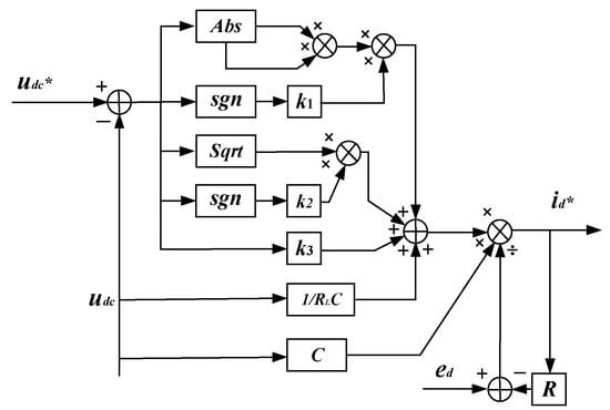
Figure 4.
Block diagram of V-SMC voltage outer loop system.
3.2. FLC-SMC Current Inner Loop Slide Mode Controller
Due to the nonlinear characteristics of the PWM rectifier control system, while the current loop has strong coupling, which leads to the difficulty of designing the control system, we consider linearizing the nonlinear system while decoupling. In this paper, we apply the knowledge of differential geometry and use the FLC method to convert the nonlinear problem into a linear one, and then combine it with the sliding mode control strategy to design the current inner loop FLC-SMC controller.
From Equation (3), the equation of state of the rectifier in the two-phase rotating coordinate system is:
We take the system state vector to be , the input state vector to be , the output state vector to be and then rewrite the state equation as a mathematical model of the affine nonlinear system with two inputs and two outputs:
From Equation (19), we can see that , .
The two-input and two-output affine nonlinear system is verified according to the conditions for the exact linearization of nonlinear systems [21,22,23,24], and the conditions are satisfied and Equation (19) can be linearized.
Taking the Lie derivative of Equation (19) yields:
In the formula:
Assuming that the decoupling matrix A(x) is non-singular, Equation (22) can be expressed as:
Included among these are , .
Take the state feedback control rate as Equation (22), where :
The dynamic equation between input and output can be obtained by bringing Equation (22) into Equation (21):
At the same time, we know that can be obtained:
Through the above calculations, the nonlinear system synthesis problem of the three-phase voltage PWM rectifier is converted into a linear system synthesis problem, which is indirectly realized by designing a linear controller. v1 and v2 refer to the input function under the linear system; y is the output function of the linear system, where it represents the active current and reactive current , respectively. When the rectifier is operated in steady state, it outputs active current and reactive current .
The role of the current inner loop in the system is to make the actual current value track the commanded current value, which ultimately makes the current satisfy and , so the sliding mode surface is selected as:
Derivation on both sides gives:
When the exponential reaching law is used as the reaching law for the sliding mode control, it can be obtained by combining Equation (24):
When the system is in steady-state operation, and denote the active command current and the reactive command current, respectively, with the active current being a constant value and the reactive current set to 0. This can be obtained from Equations (22) and (27):
In accordance with Equation (28), the feedback linearized current inner loop sliding mode control block diagram based on the exponential reaching law is shown in Figure 5.
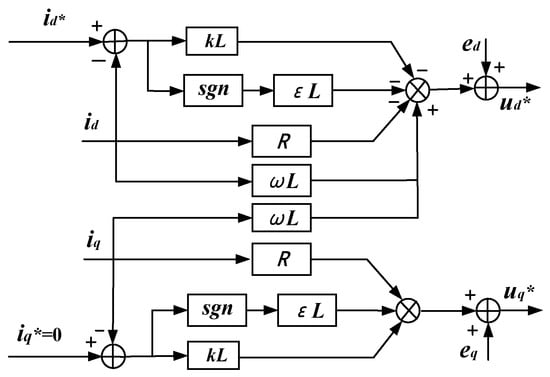
Figure 5.
FLC-SMC current inner loop control system block diagram.
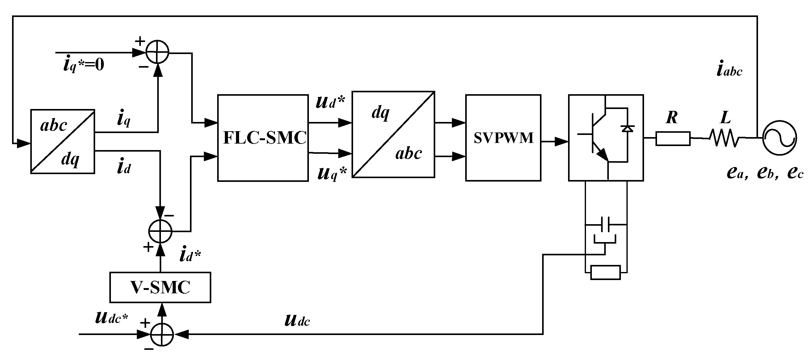
In summary, in accordance with Equations (17) and (28), the three-phase voltage PWM rectifier double closed-loop sliding mode control block diagram is shown in Figure 6.
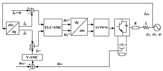
Figure 6.
Block diagram of dual-closed-loop sliding mode control strategy for three-phase voltage PWM rectifier.
4. Simulation Verification
In the previous section, a principle analysis of the double-closed-loop sliding mode control strategy based on the exponential reaching law and feedback linearization was carried out, and then a variable speed reaching law that can be varied with the system state was proposed and a new double-closed-loop sliding mode control structure was designed. In this section, simulation experiments will be carried out via Matlab/Simulink to compare the PI control, SMC control and the V-SMC control strategy proposed in this paper to illustrate the superiority and feasibility of the new control strategy, and the system parameters of the simulation model are shown in Table 1.

Table 1.
Rectifier system parameters.
The controller design parameters are shown in Table 2.
Table 2.
Controller parameters.
The advantages and disadvantages of the V-SMC control strategy, SMC control and PI control strategy proposed in this paper are compared in terms of their performance in terms of five aspects, namely, start-up response speed of the system, dynamic performance when fluctuations in the AC-side voltage and frequency occur, harmonic content of the AC side, unit power factor and frequency.
4.1. System Start-Up Response
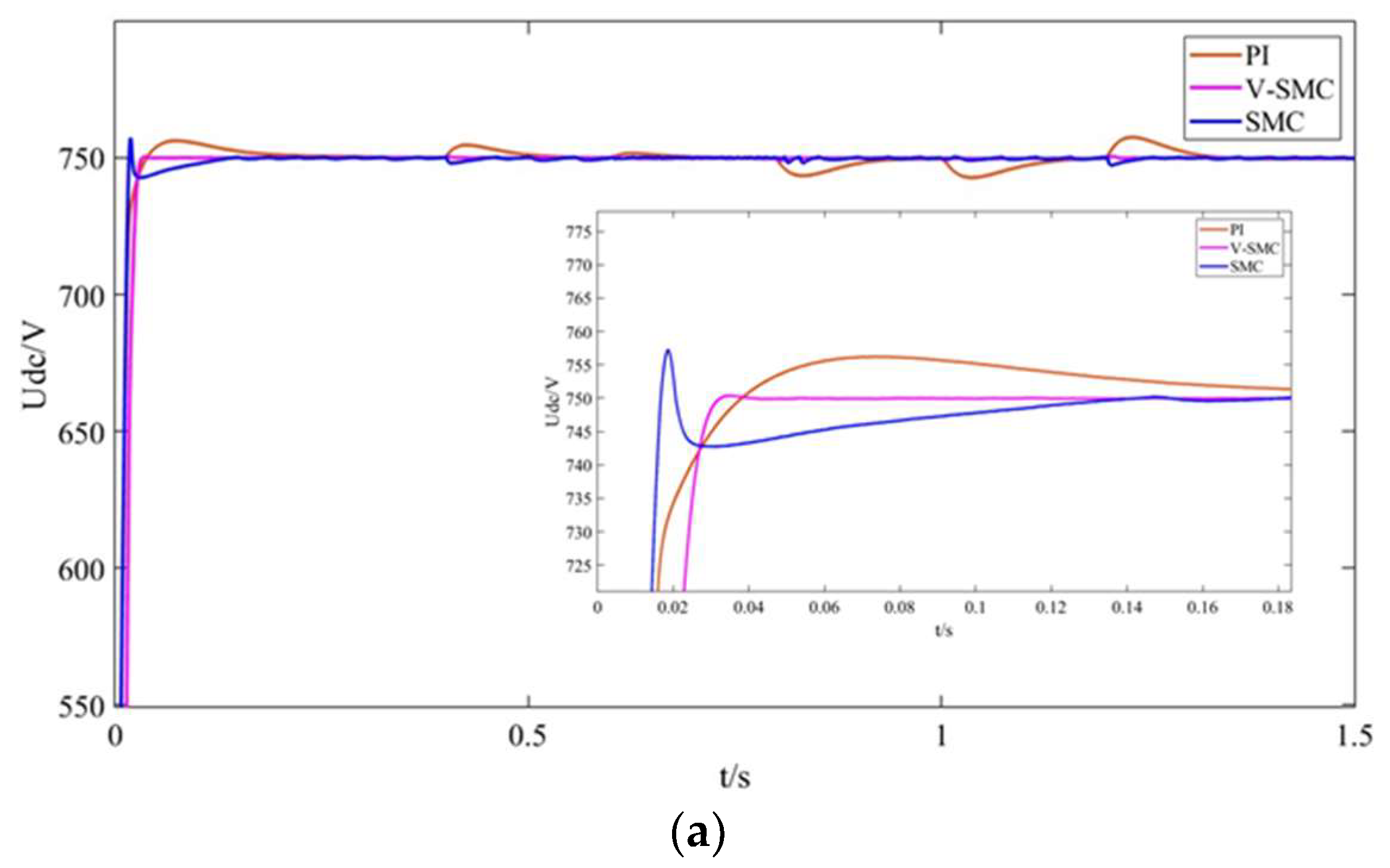
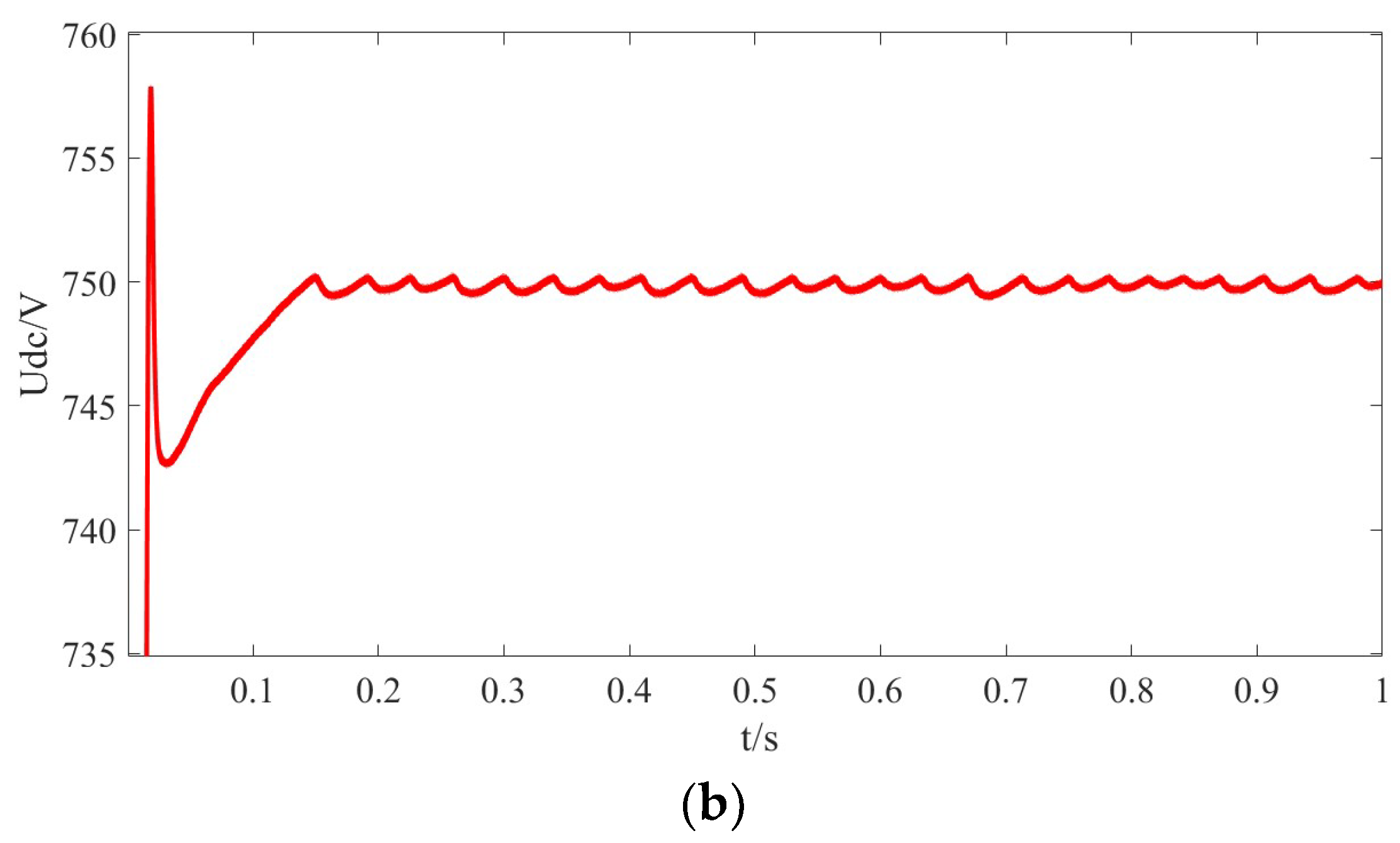
Figure 7a shows the waveforms of the output voltage when the system starts up. The PI control reaches a steady state at 0.2 s with an overshooting amount of about 7 V; the SMC control reaches a steady state at 0.13 s with an overshooting amount of about 8 V; and the V-SMC control strategy reaches steady state at about 0.03 s with no overshooting. The variable speed convergence law sliding mode control strategy proposed in this paper has the shortest time for the DC-side voltage to reach the steady state and the fastest response speed, while the voltage has no overshooting amount, and it has good dynamic and steady-state performances compared with the traditional PI control and SMC control.
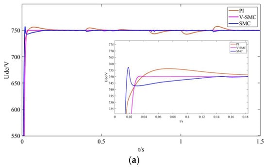
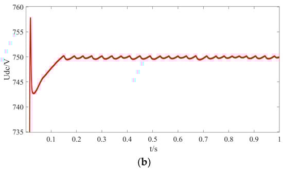
Figure 7.
Simulated waveform of DC-side voltage. (a) DC-side voltage starting performance of three control strategies. (b) SMC DC-side output voltage dither.
From Figure 7b and Figure 9, we can find that there is a voltage jitter of about 0.5 V up and down in the DC output voltage under the traditional SMC control strategy, whereas the DC-side output voltage is almost ripple-free under the PI control and the new variable speed convergence law smooth-mode control strategy.
4.2. Analysis of Three-Phase Voltage and Current Waveforms on the AC Side
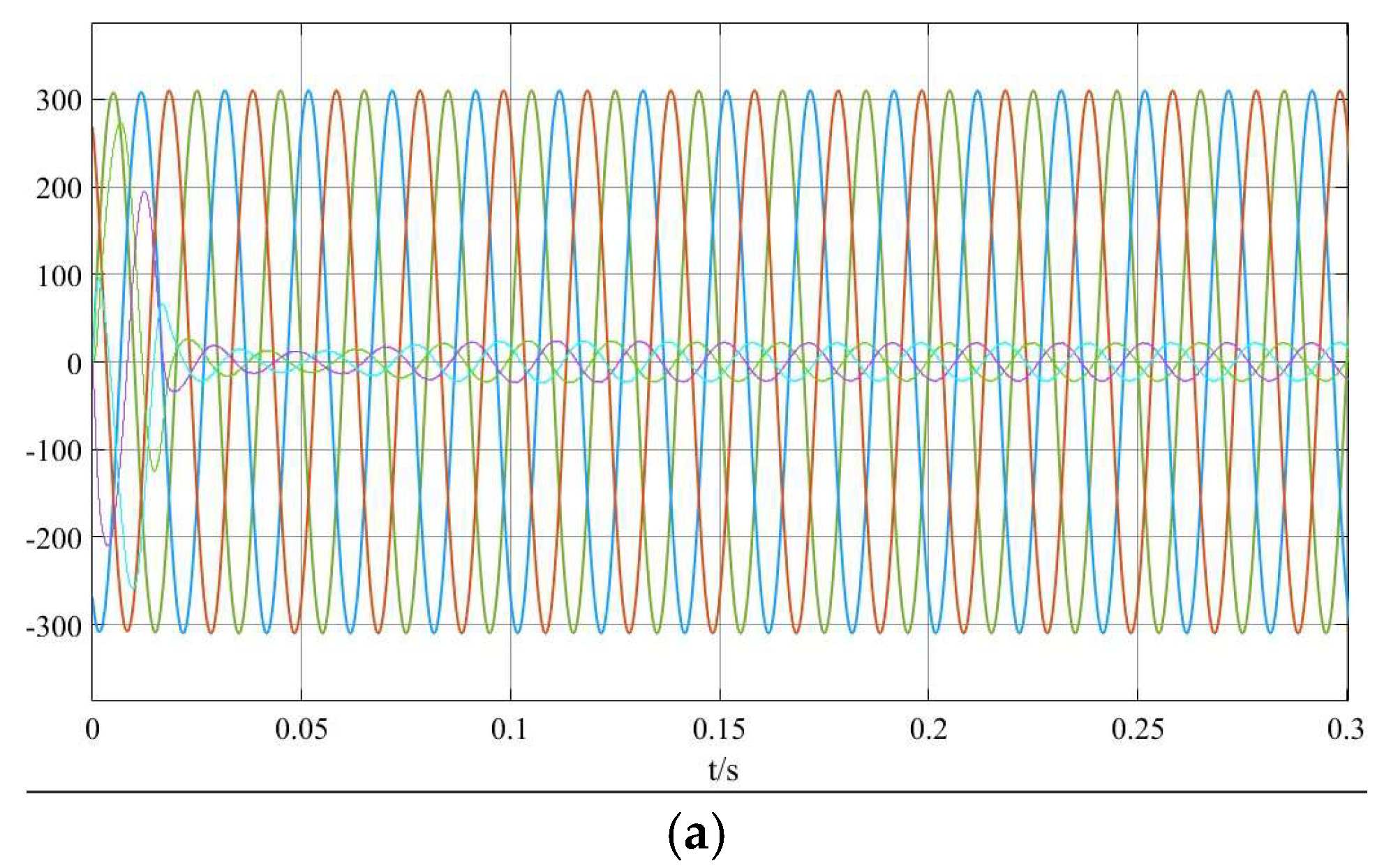
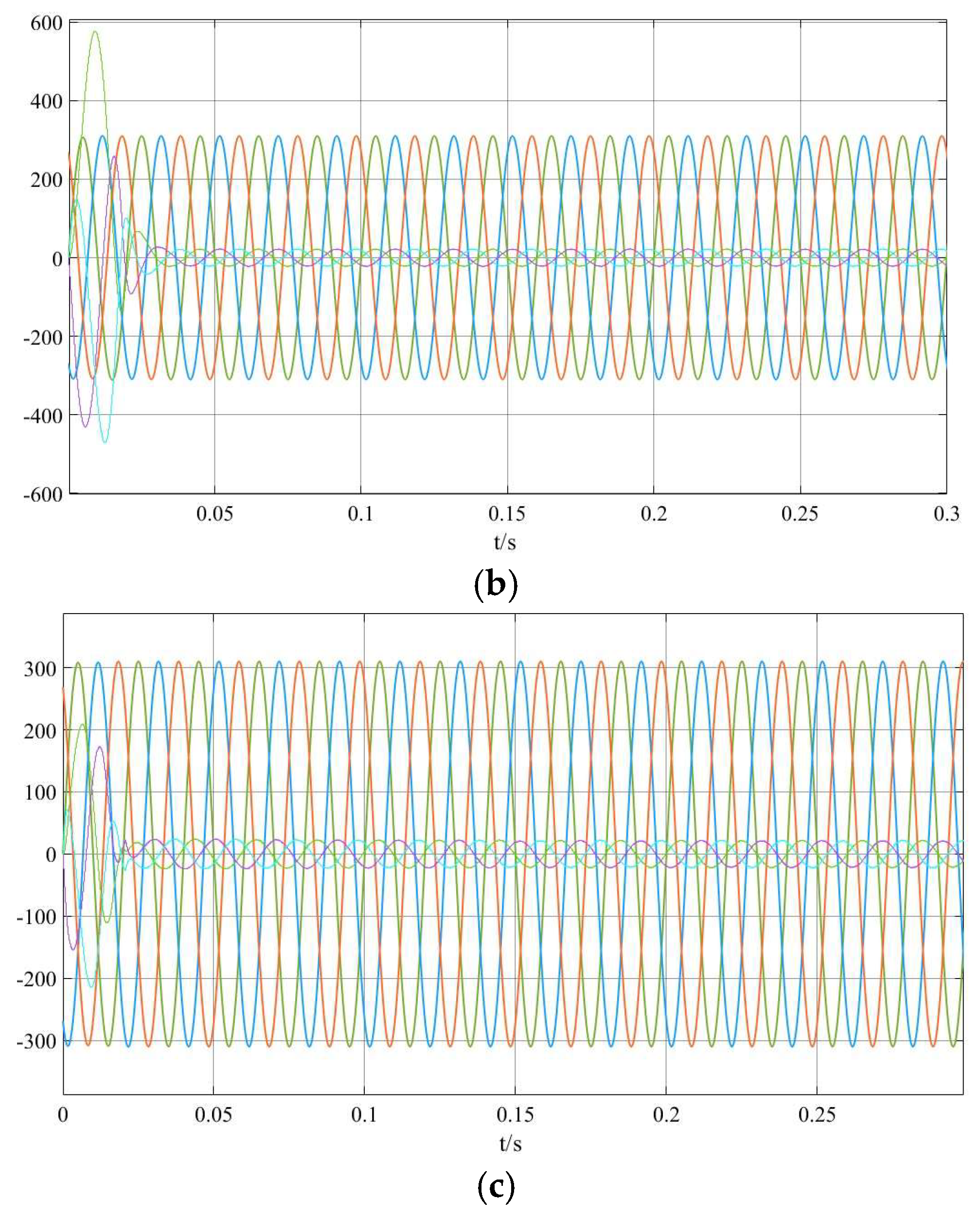
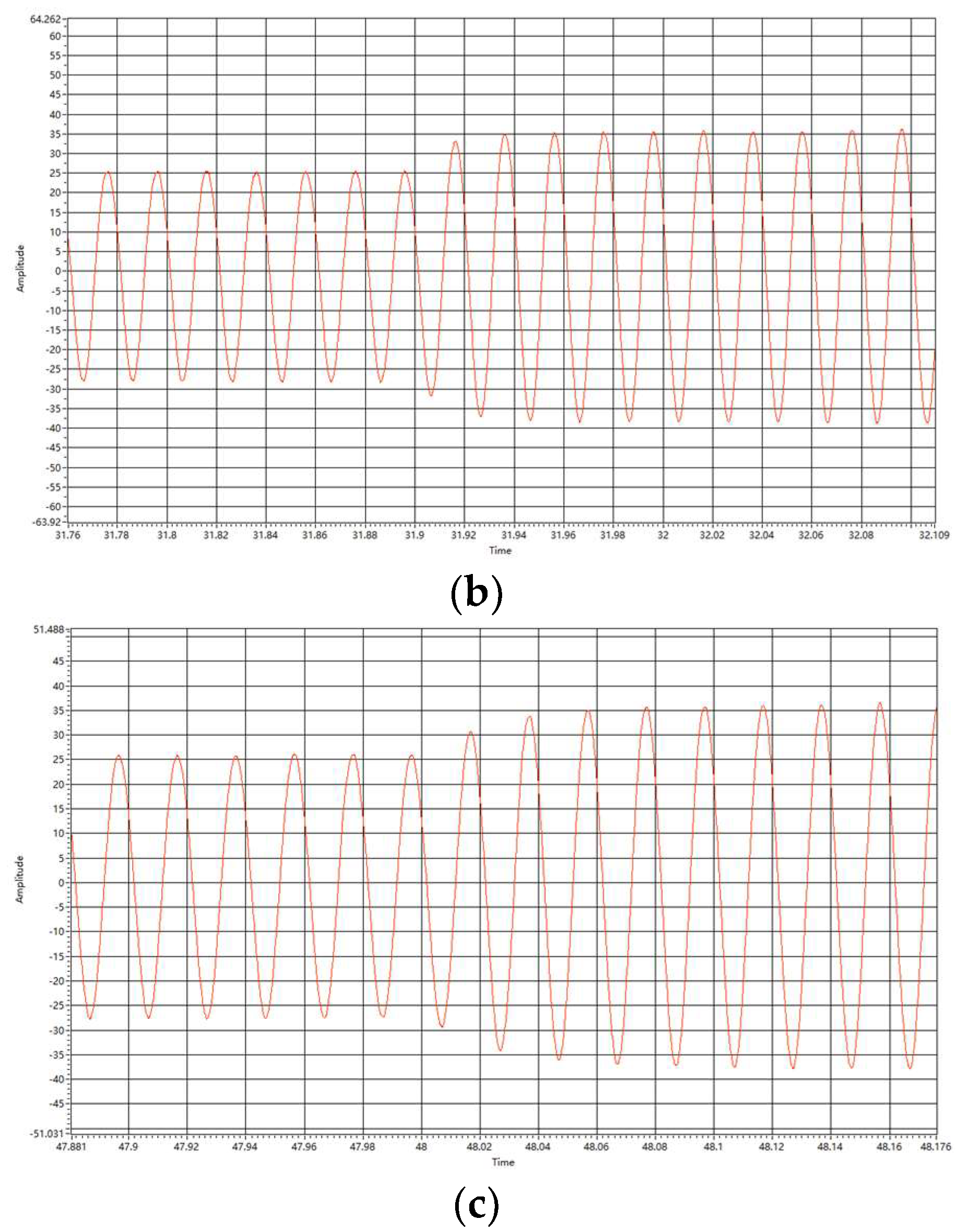
Figure 8 shows the three-phase voltage and current waveforms of the AC side under the three control strategies. It can be found that the time for the three-phase current to reach steady state under the PI control strategy is longer than that of the other two control methods, and it takes 0.1 s for the three-phase current to reach a steady state under the PI control strategy, while the other two control methods reach a steady state in 0.02 s after start up. It is also found that there are start-up inrush currents under all three control strategies, the start-up inrush current is the largest under the SMC control strategy, and the start-up inrush current is the smallest under the V-SMC control strategy, but it is still very large. The unit power factor characteristics are very good under all three control strategies.
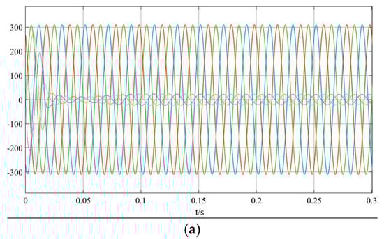
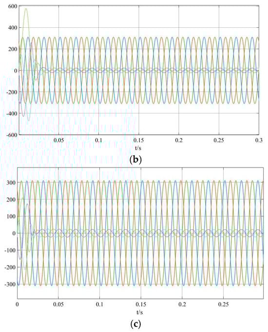
Figure 8.
Simulated waveforms of three-phase voltage and current on AC side. (a) PI control strategy. (b) SMC control strategy. (c) V-SMC control strategy.
4.3. Dynamic Response to Changes in AC-Side Voltage and Frequency
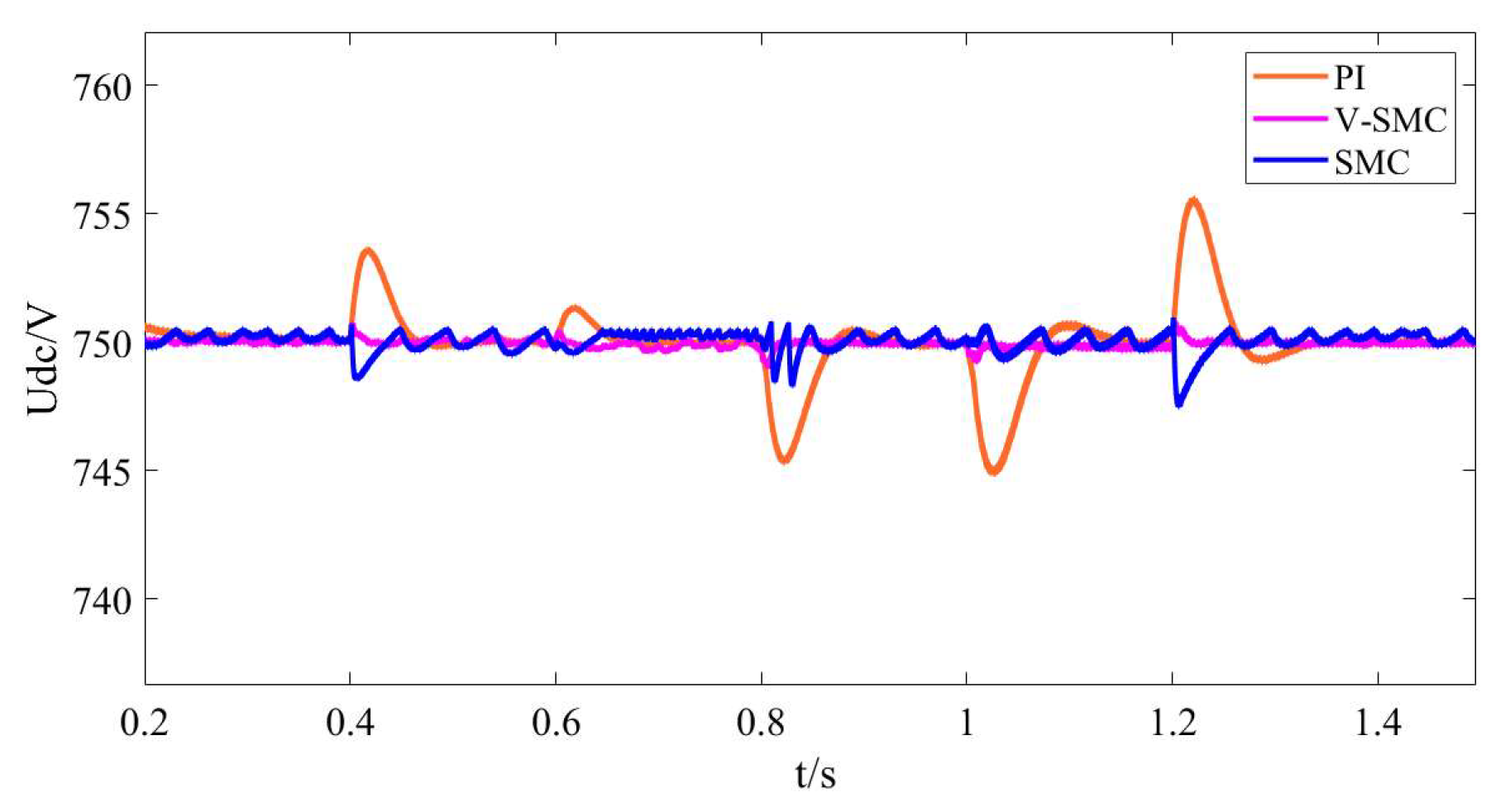
Figure 9 shows the waveforms of DC output voltage when the AC side of the system is wide input. A value of 0.4 s is found when the motor speed is changed from rated value to overspeed, the RMS value of the three-phase AC power is 264 V and the frequency is 60 Hz; a value of 0.6 s is found when it is still overspeed, the RMS value is 286 V and the frequency is 65 Hz; a value of 0.8 s is found when the motor is restored to the normal operation state, the RMS value is 220 V and the frequency is 50 Hz; a value of 1 s is found when the motor speed is below the rated speed, the RMS value is 176 V and the frequency is 40 Hz; a value of 1.2 s is found when the motor is restored to the normal operation state, the RMS value is 220 V and the frequency is 50 Hz. A value of 1 s is found when the motor speed is lower than the rated speed, the effective value is 176 V and the frequency is 40 Hz; a value of 1.2 s is found when the motor returns to the normal running state, the effective value is 220 V and the frequency is 50 Hz. Through the simulation results, it can be found that with the output voltage under the PI control strategy there is a voltage jitter of 2–5 V, and at the same time the regulation time is between 0.05 and 0.15 s, and the dynamic performance is poor; SMC has a voltage jitter of 1–3 V. A 1–3 V voltage jitter, while the response speed is about 0.05 s, compared with the traditional PI control strategy, is a big improvement, but there is the inherent jitter of SMC; the V-SMC control strategy proposed in this paper has almost no voltage jitter, and the response speed is very fast, and the voltage is restored to the desired value in about 0.015 s. Voltage overshoot, regulation time and power quality have better dynamic performance and robustness.
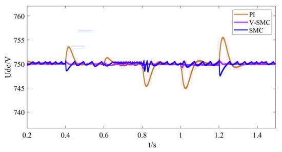
Figure 9.
Simulated waveforms of DC-side voltage at wide input on AC side.
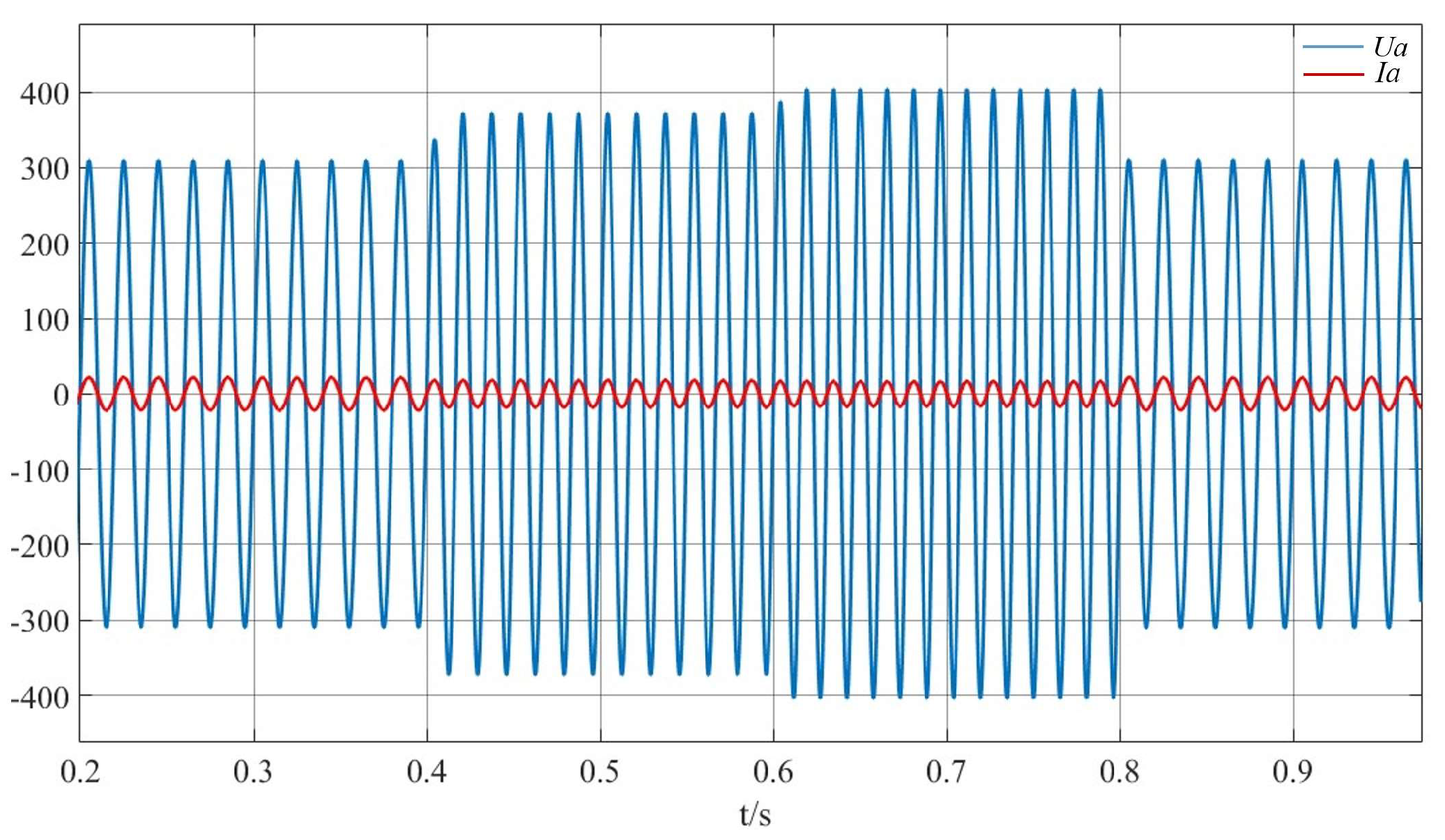
Figure 10 shows the A-phase voltage and current output waveforms at wide input on the AC side of the system under the new control strategy. When the voltage and frequency change, it can quickly return to the stable operation state with fast response speed and good phase-tracking capability.
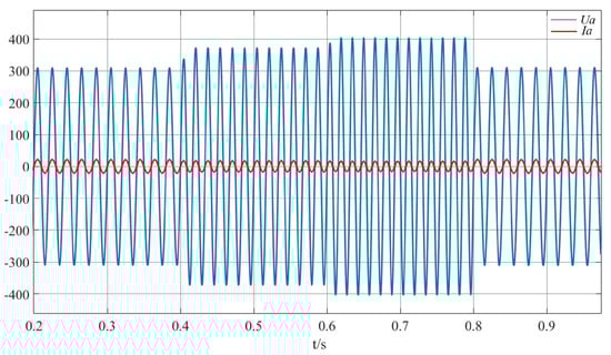
Figure 10.
A-phase voltage and current waveforms at wide input on AC side. The red line represents phase A current and the blue line represents phase A voltage.
4.4. Comparative Analysis of Harmonic Content on AC Side
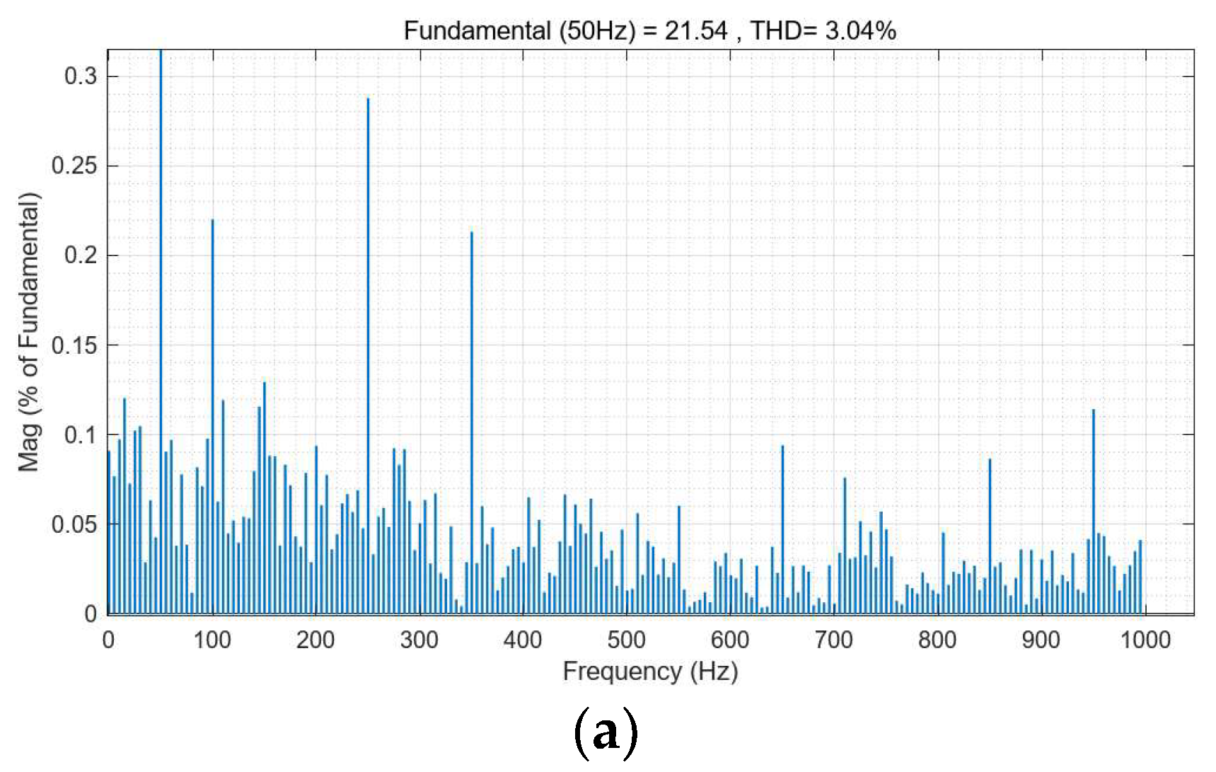
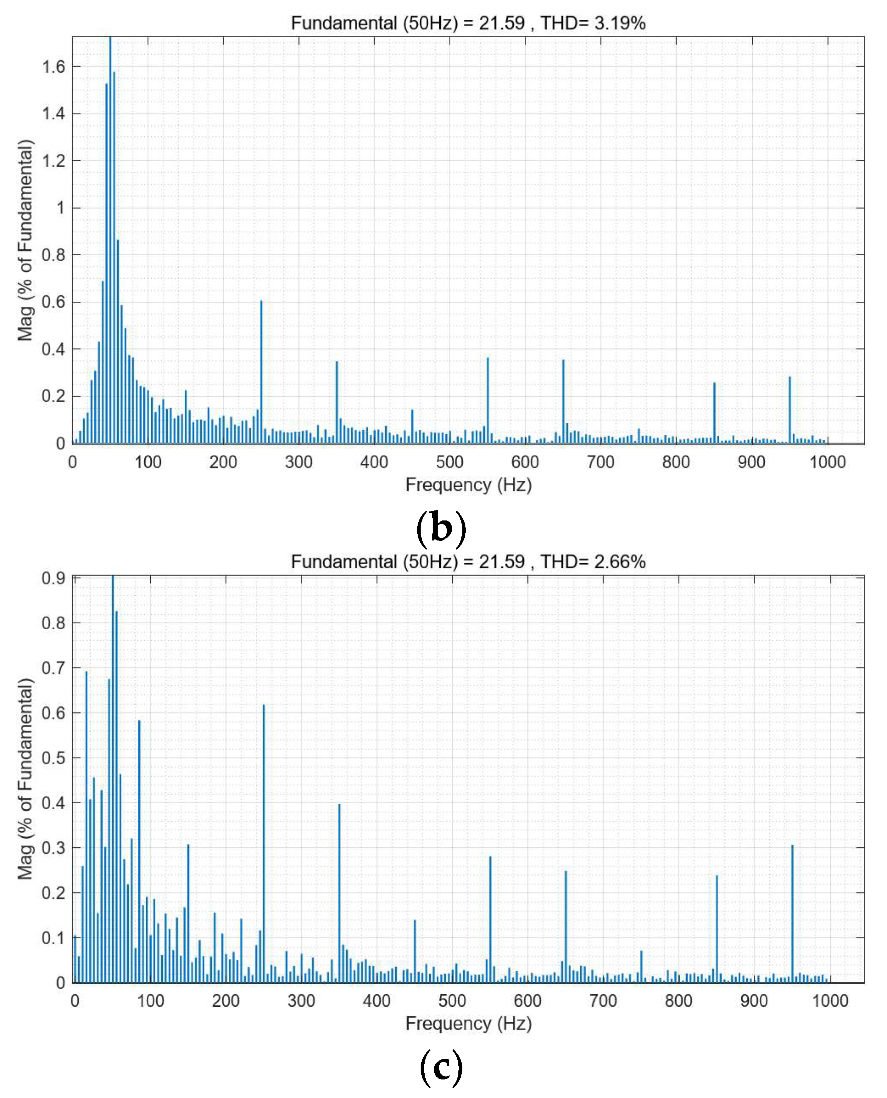
Figure 11 shows a comparative analysis of the harmonic content of the AC side under the three control strategies. The SMC, due to the existence of its own jitter problem, has a harmonic content of 3.19%, which is slightly higher than that of the PI control strategy of 3.04%, and the harmonic content of the control strategy proposed in this paper is 2.66%; the harmonic content of all the three satisfies the technical index of harmonic content lower than 5%, but the V-SMC harmonic content control is more excellent.
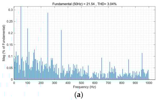
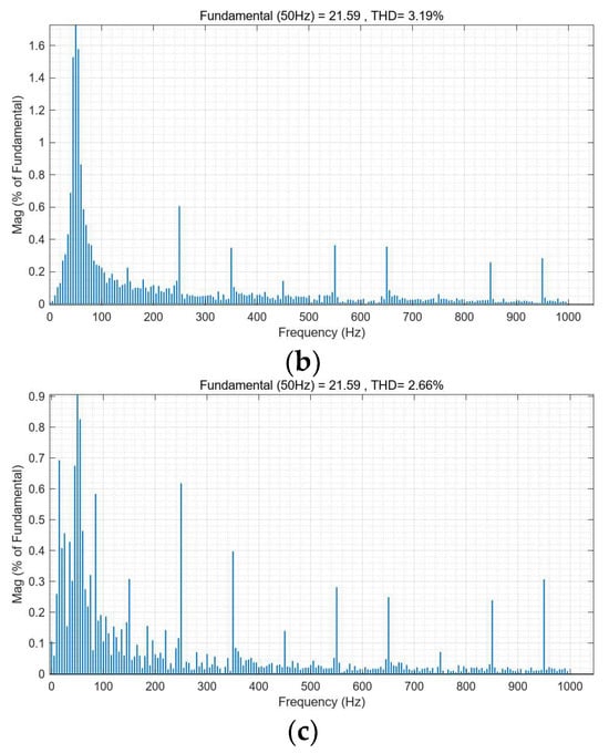
Figure 11.
Harmonic content of AC side of the system under three control strategies. (a) PI control strategy. (b) SMC control strategy. (c) V-SMC control strategy.
4.5. Power Factor Analysis
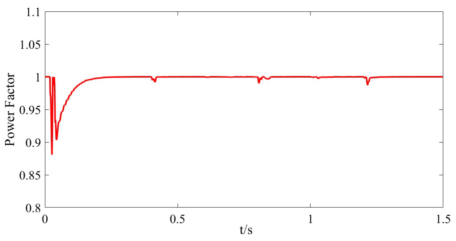
From Figure 12, it can intuitively be seen in the PWM rectifier steady-state operation that it is fully able to achieve normal operation under the unit power factor; in the case of AC-side voltage and frequency fluctuations, it is also able to quickly return to the unit power factor operation state, and there is almost no fluctuation; the power factor is maintained at above 0.99; the dynamic performance is very good.
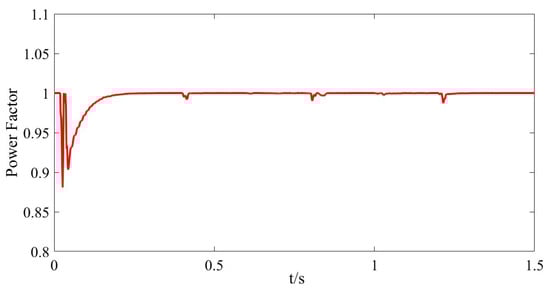
Figure 12.
Power factor analysis under the novel control strategy.
4.6. Frequency Analysis
Figure 13 shows the waveforms corresponding to the frequency change of the control strategy proposed in this paper when the AC side of the rectifier has a wide input. As can be seen from the figure, the phase-locked loop can accurately perform phase locking, and can recover to the corresponding frequency value in a very short time when the voltage amplitude and frequency of the AC-side change abruptly, and the fluctuation is small, which has almost no effect on the rectifier.
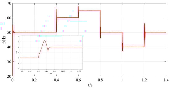
Figure 13.
Analysis of frequency variation under novel control strategy.
5. Experimental Verification
In order to verify the feasibility and superiority of the novel variable speed convergence law smooth-mode control strategy, a 10 kW rectifier system is built on a semi-physical experimental platform to verify its steady-state performance and dynamic.
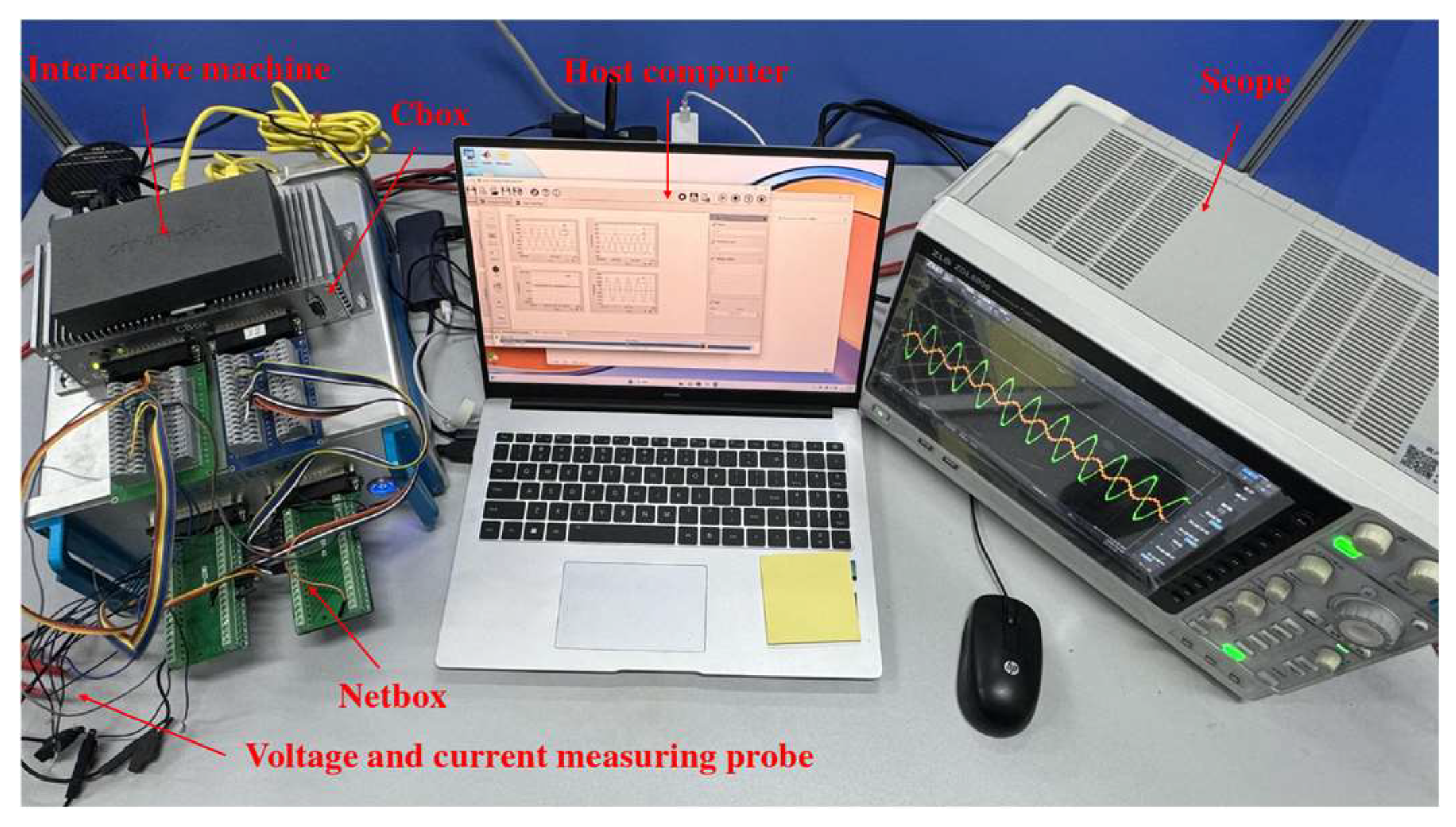
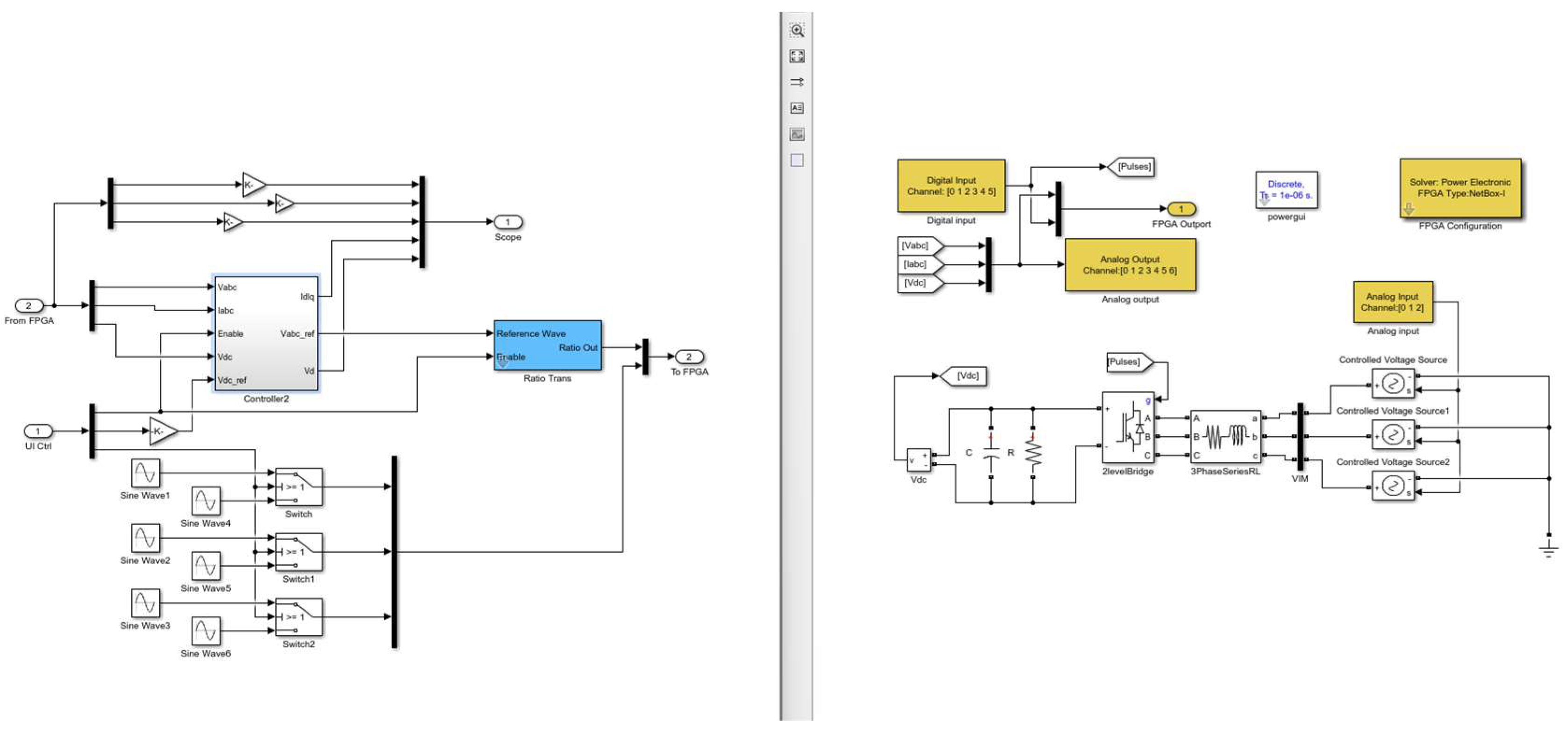
Figure 14 shows the semi-physical experimental platform used to verify the control strategy proposed in this paper. It consists of several parts: host computer, scope, Cbox, Netbox, interactive machine and voltage and current measuring probe. The analogue signals output from the corresponding ports of the Netbox board are measured via the voltage and current probes, and the analogue signals are transmitted to the CPU + FPGA module of the Cbox, which carries the control part, generates the digital signals through the arithmetic operation and transmits them into the Netbox, forming a closed-loop process, thus realizing the experimental verification. In the whole process, the interoperator allows the host computer, Cbox and Netbox to achieve real-time interconnection; in the host computer, the hardware part and the control part of the simulation model are divided and then loaded into the Netbox and the Cbox, respectively, through DeskSim 22.0.5.0; the oscilloscope monitors the waveforms of the required observation signals in real time. Figure 15 shows the model loaded via DeskSim software after differentiation.
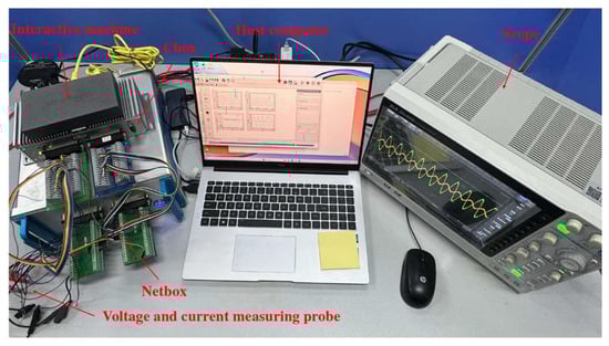
Figure 14.
Experimental platform.
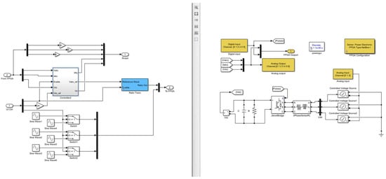
Figure 15.
The differentiated simulation model loaded via DeskSim software.
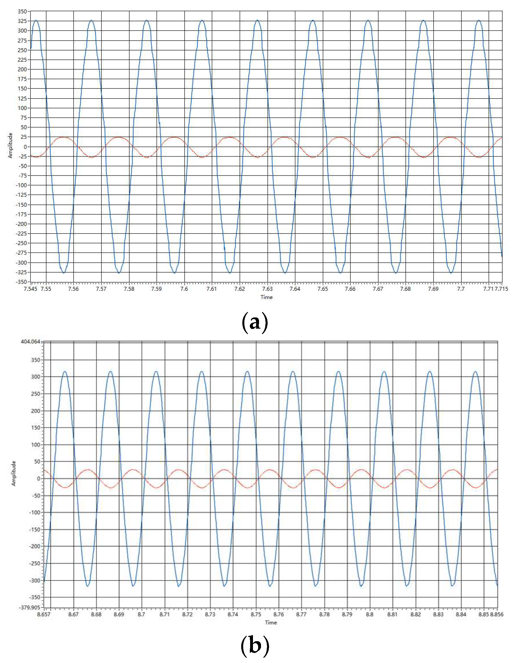
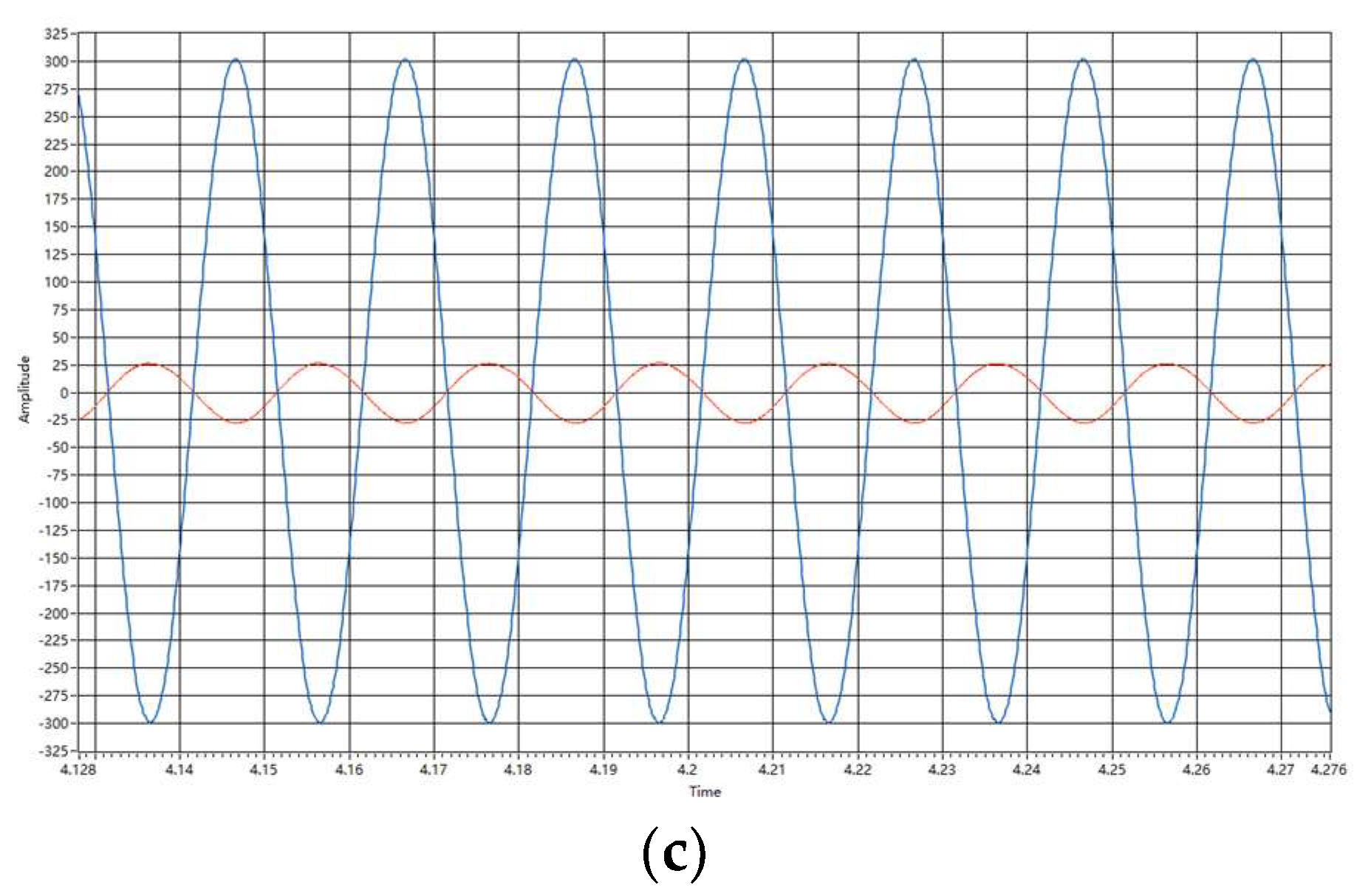
Figure 16 shows the experimental waveforms of the AC-side phase A voltage and current at steady state, the red line represents the AC side current value of phase A, The blue line represents the AC side voltage value of phase A. It can be seen that the voltage and current waveforms under the V-SMC control strategy have the highest sinusoidal degree and can better suppress harmonics, and the voltage and current waveforms under the PI control strategy have a poor sinusoidal degree, which is consistent with the simulation analysis results.
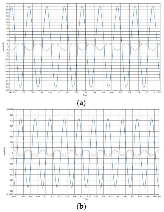
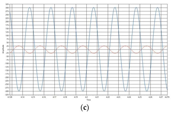
Figure 16.
A-phase voltage and current waveforms on the AC side at steady state. (a) PI control strategy. (b) SMC Control Strategy. (c) V-SMC control strategy.
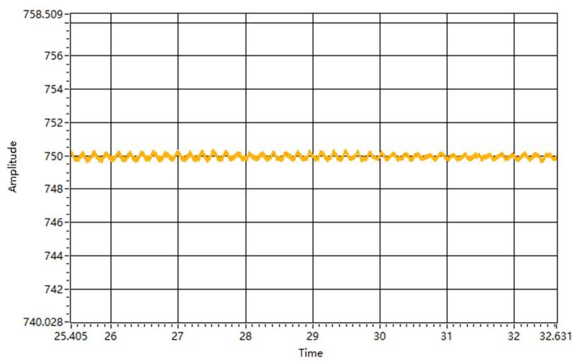
Through Figure 17, it can be found that the DC-side voltage is stable at about 750 V under the SMC control strategy, and there exists a voltage jitter of about 0.4 V up and down, which is the jitter of the intrinsic frequency that exists in the traditional sliding mode control.

Figure 17.
DC-side output voltage waveform at steady state under SMC control strategy.
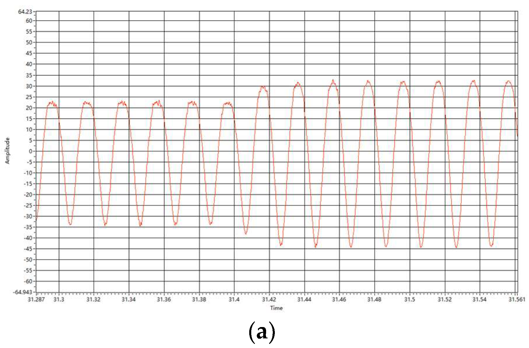
Figure 18 shows that the traditional PI control strategy has high harmonic distortion and low sinusoidal degree with respect to the current waveform in the wide input condition of the voltage source on the AC side; the current harmonic distortion of the SMC control strategy is small, and the current harmonic distortion of the V-SMC control strategy is the smallest; the results of the simulation and analysis are verified via experiments, and at the same time the design requirements are met.
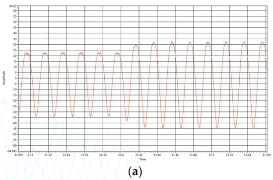
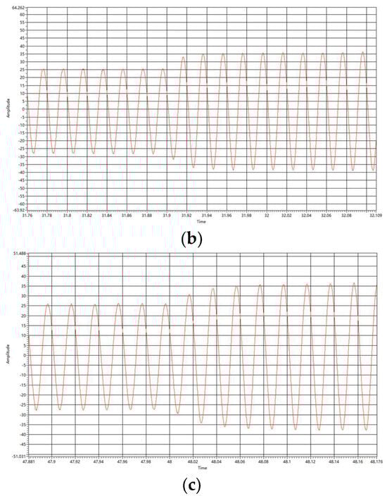
Figure 18.
A-phase current waveform of AC side during dynamic change. (a) PI control strategy. (b) SMC Control Strategy. (c) V-SMC control strategy.
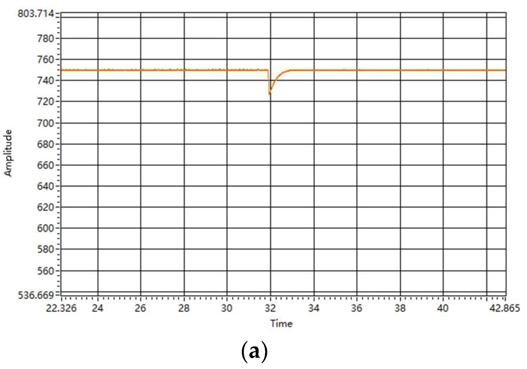
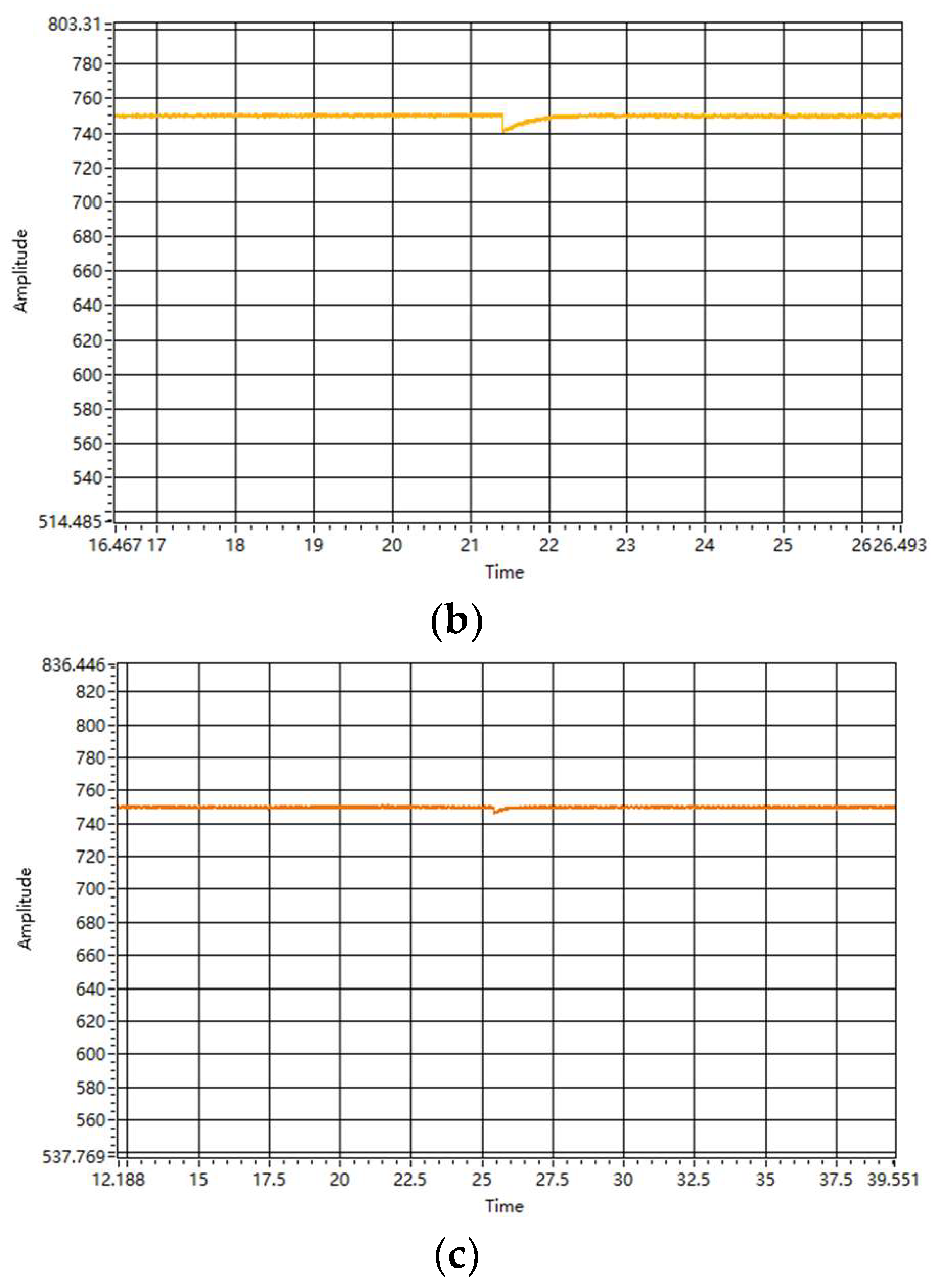
Figure 19 shows the DC-side voltage waveforms under the three control strategies: under the PI control strategy, the voltage has a voltage jitter value of about 25 V and reaches a steady state in about 0.08 s; under the SMC control strategy, the voltage has a voltage jitter value of about 10 V and returns to a steady state in about 0.1 s; under the V-SMC control strategy, the voltage has a voltage jitter value of about 2 V and reaches a steady state in about 0.04 s; and under the V-SMC control strategy, the voltage has a voltage jitter value of about 2 V. and reaches the steady state in about 0.04 s. Although there is a difference between the voltage fluctuation value shown in the experiment and that shown in the simulation, the difference is not large, and at the same time, the control effect under the V-SMC control strategy is the best, so the experiment can reflect the superiority of the control strategy proposed in this paper.
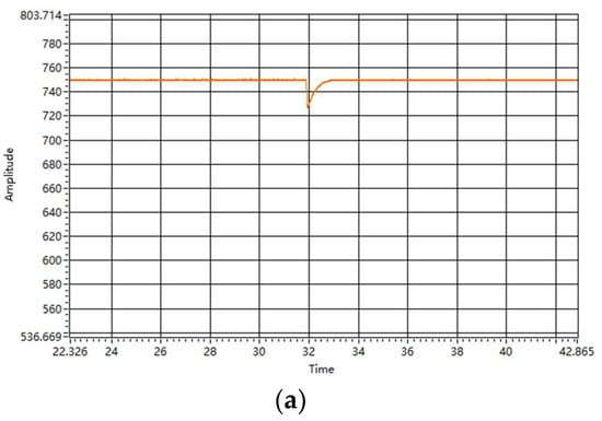
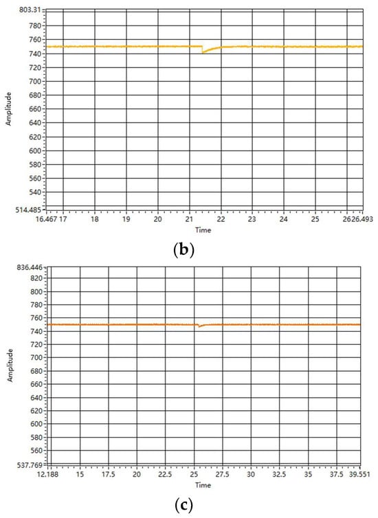
Figure 19.
DC-side output voltage waveform during dynamic change. (a) PI control strategy. (b) SMC control strategy. (c) V-SMC control strategy.
6. Conclusions
In order to suppress the self-jitter existing in the sliding mode control of the three-phase voltage-type PWM rectifier, and at the same time to use the control method applicable to the nonlinear system, a new design of the double-closed-loop sliding mode controller is carried out by combining the two methods of the new variable speed convergence rate and the feedback linearization. The simulation model is constructed via Matlab/Simulink, and the simulation results under PI, SMC and V-SMC control strategies are compared to verify that the new control strategy proposed in this paper has the advantages of good dynamic performance, strong robustness and strong anti-jamming ability, and at the same time, compared with the traditional SMC, the jitter vibration suppression effect is obvious. The proposed control strategy is further verified to have good steady state and dynamic performance by building a semi-physical experimental platform.
Author Contributions
Conceptualization, F.L.; methodology, Y.X.; software, L.Y.; validation, B.Z., Y.X. and F.L.; formal analysis, F.L.; investigation, Y.X.; resources, Y.X.; data curation, F.L.; writing—original draft preparation, F.L.; writing—review and editing, F.L.; visualization, B.Z.; supervision, L.Y.; project administration, B.Z.; funding acquisition, Y.X. All authors have read and agreed to the published version of the manuscript.
Funding
This research was funded by the National Natural Science Foundation of China (Grant No. 52277206 and 51877212).
Data Availability Statement
The data that support the findings of this study are available from the corresponding author upon reasonable request.
Conflicts of Interest
The authors declare no conflicts of interest.
References
- Wang, X.G.; Ma, C.L. Development and Utilisation of Marine Renewable Energy Resources under the “Double Carbon” Target. Huadian Power Technol. 2021, 43, 91–96. [Google Scholar]
- Yang, S.M.; Wang, J. Development status and future trend of global energy pattern. Int. Financ. 2014, 3, 44–51. [Google Scholar] [CrossRef]
- Publication and implementation of the National Plan for the Protection of Sea Islands. Mar. Dev. Manag. 2012, 29, 37.
- Chang, Z.; Bao, D.Z.; Liu, Z.Z. Development of marine current energy development and utilisation technology and key technical considerations. Sol. Energy 2012, 6, 55–59. [Google Scholar]
- Fang, Y.Z.; Wu, H. Methods and analyses of tidal energy resources assessment in major waterways of Zhoushan Islands. Geogr. Inf. World 2022, 29, 118–124. [Google Scholar]
- Gu, Y.J.; Li, W.; Liu, H.W. Power law control and grid-connected operation of tidal power generation system. J. Zhejiang Univ. (Eng. Ed.) 2017, 51, 1974–1980. [Google Scholar]
- Zhejiang University Zhoushan Ruo Island Current Power Generation Test Site. Sci. Technol. Her. 2021, 39, 117.
- Cheng, Q.M.; Cheng, Y.M.; Xue, Y. A review on the development of three-phase voltage source PWM rectifier control methods. Power Syst. Prot. Control 2012, 40, 145–155. [Google Scholar]
- Cheng, Q.M.; Chen, Y.; Sun, Y.H. MMC-PET feedback linearised sliding mode control strategy under grid voltage unbalance. South. Power Grid Technol. 2024, 1–8. [Google Scholar]
- Xue, T.L.; Chen, Z.Q.; Zhang, X.J. Application of sliding mode variable structure control in three-phase voltage-type PWM rectifier. Electr. Drives 2018, 48, 21–26. [Google Scholar]
- Gao, R.H.; Chen, Y.; Ma, C.Y. Structural design and performance simulation of three-phase PWM rectifier based on sliding mode control. J. Taiyuan Univ. Technol. 2018, 49, 258–263. [Google Scholar]
- Liang, Q.Q.; Cheng, X.F.; Zhang, Y.H. Sliding mode control strategy for three-phase PWM rectifiers with high-order integral end-slip mode. Grid Clean Energy 2022, 38, 37–43. [Google Scholar]
- Wang, H.Y.; Zhang, Y.T.; Zhang, Q. Research on a sliding mode observer-based control strategy for rolling stock rectifier. Power Syst. Prot. Control 2022, 50, 81–91. [Google Scholar]
- Hu, C.B.; Wang, Y.; Luo, S. Voltage control strategy of islanded three-phase voltage source converter under unbalanced loads based on disturbance observer. In Proceedings of the 2018 21st International Conference on Electrical Machines and Systems (ICEMS), Korea, Republic of South, 7–10 October 2018; pp. 2199–2204. [Google Scholar]
- Wang, H.; Nie, J.Y.; Li, B. Fractional-order smooth-mode control strategy for AC/DC hybrid microgrid interconnection interface converter under grid voltage imbalance. Power Syst. Prot. Control 2023, 51, 94–103. [Google Scholar]
- Xu, P.; Su, X.; Guo, C. Model predictive sliding mode control of three-phase voltage-based PWM rectifiers. J. Electr. Eng. 2023, 18, 58–65. [Google Scholar]
- Wang, S.Z.; Jia, W.C.; Li, L.L.; Li, S. Research on control strategy of Vienna rectifier based on sliding mode control. J. Phys. Conf. Ser. 2022, 2355, 012039. [Google Scholar] [CrossRef]
- Hafiz, A.; Doğan, Ç. Sliding mode based adaptive linear neuron proportional resonant control of Vienna rectifier for performance improvement of electric vehicle charging system. J. Power Sources 2022, 542, 231788. [Google Scholar]
- Gadgune, S.; Joshi, M.P. Control of Three-Phase PWM Rectifier as Virtual Synchronous Machine Using an Integral Sliding Mode Controller. J. Inst. Eng. (India) Ser. B 2021, 102, 1–9. [Google Scholar] [CrossRef]
- Wang, M.; Wang, H.; Shi, Y. A modified sliding-mode controller-based mode predictive control strategy for three-phase rectifier. Int. J. Circuit Theory Appl. 2020, 48, 1564–1582. [Google Scholar] [CrossRef]
- Deng, W.H.; Zhang, B.; Qiu, D.Y. Accurate linearised decoupling control of three-phase voltage PWM rectifier with state feedback. Chin. J. Electr. Eng. 2005, 25, 97–103. [Google Scholar]
- Li, D.D.; Sun, X.X.; Dong, W.H. Longitudinal control law design of sliding mode variable structure reloaded airdrop based on linearised feedback. Control Theory Appl. 2013, 30, 54–60. [Google Scholar]
- Hu, Y.M. Theory and Application of Variable Structure Control; Science Publishing House: Beijing, China, 2003. [Google Scholar]
- Wang, J. Nonlinear Control of Voltage-Type PWM Rectifier; Mechanical Industry Press: Beijing, China, 2008; pp. 115–117. [Google Scholar]


Disclaimer/Publisher’s Note: The statements, opinions and data contained in all publications are solely those of the individual author(s) and contributor(s) and not of MDPI and/or the editor(s). MDPI and/or the editor(s) disclaim responsibility for any injury to people or property resulting from any ideas, methods, instructions or products referred to in the content. |
© 2024 by the authors. Licensee MDPI, Basel, Switzerland. This article is an open access article distributed under the terms and conditions of the Creative Commons Attribution (CC BY) license (https://creativecommons.org/licenses/by/4.0/).