Article

Multifunctional Superconducting Magnetic Energy Compensation for the Traction Power System of High-Speed Maglevs

1
Institute of Rail Transit, Tongji University, Shanghai 201804, China
2
Maglev Transportation Engineering R&D Center, Tongji University, Shanghai 201804, China
3
College of Electrical Engineering, Sichuan University, Chengdu 610065, China
4
School of Engineering, Sichuan Normal University, Chengdu 610101, China
5
Clare Hall, University of Cambridge, Cambridge CB3 9AL, UK
*
Authors to whom correspondence should be addressed.
Electronics 2024, 13(5), 979; https://doi.org/10.3390/electronics13050979
Submission received: 6 December 2023 / Revised: 20 February 2024 / Accepted: 28 February 2024 / Published: 4 March 2024

Abstract

:
With the global trend of carbon reduction, high-speed maglevs are going to use a large percentage of the electricity generated from renewable energy. However, the fluctuating characteristics of renewable energy can cause voltage disturbance in the traction power system, but high-speed maglevs have high requirements for power quality. This paper presents a novel scheme of a high-speed maglev power system using superconducting magnetic energy storage (SMES) and distributed renewable energy. It aims to solve the voltage sag caused by renewable energy and achieve smooth power interaction between the traction power system and maglevs. The working principle of the SMES power compensation system for topology and the control strategy were analyzed. A maglev train traction power supply model was established, and the results show that SMES effectively alleviated voltage sag, responded rapidly to the power demand during maglev acceleration and braking, and maintained voltage stability. In our case study of a 10 MW high-speed maglev traction power system, the SMES system could output/absorb power to compensate for sudden changes within 10 ms, stabilizing the DC bus voltage with fluctuations of less than 0.8%. Overall, the novel SMES power compensation system is expected to become a promising solution for high-speed maglevs to overcome the power quality issues from renewable energy.

1. Introduction

Maglev transportation has advantages such as high speed, good stability, high safety, and strong adaptability, making it a highly competitive ground transportation option and a future development trend in railway transportation [1,2]. With the global trend of carbon neutrality, high-energy-consuming maglev transportation urgently needs to undergo a clean and low-carbon transformation of energy [3,4]. Distributed renewable energy sources are being considered to be integrated into the traction power system of railway transportation, and their research and promotion are being carried out [5,6]. Refs. [7,8,9] describe the models and development prospects of photovoltaic power systems on train station roofs and train tops. Refs. [10,11] further evaluate the potential of installing photovoltaics on land next to railway tracks, train station roofs, and train tops in the Chinese railway system, with an annual clean power generation capacity of 239.6 TWh, meeting the entire electricity demand of trains. Ref. [12] evaluates the potential of photovoltaics along the Beijing–Shanghai high-speed railway and on train station roofs, with a total power generation capacity of 5.65 GW, significantly reducing the power consumption of trains from the main grid. A 42,000 m2 photovoltaic power generation system has been installed on the roof of the Xiongan High-speed Railway Station, with a system capacity of 6 MW, which can meet 20% of the high-speed railway’s electricity demand and reduce 45 million tons of carbon dioxide emissions annually [13,14]. In addition, other renewable energy sources such as wind and hydropower are also being used for railway transportation [15,16,17].
However, due to the intermittent and fluctuating characteristics of renewable energy, traction power can be easily affected, resulting in transient voltage drops in the DC bus and other power quality issues. These issues will affect the operation of the linear traction motor of the maglev [18,19]. In addition, during the acceleration of a maglev train, if the load power of the linear traction motor has a sudden increase, the DC bus may not be able to provide sufficient power instantly, which will cause voltage drops and slow the acceleration. During the braking of a maglev train, the regenerative power from the linear motor will cause high-amplitude overvoltage in the DC bus, which can severely impact the fragile traction power system [20].
Superconducting magnetic energy storage (SMES) is one of the most promising superconducting magnet applications. An SMES system can store magnetic energy in superconducting magnets and release the stored energy when required. Compared to other commercial energy storage systems like electrochemical batteries, SMES, together with other energy storage devices, is highly suitable for rapid power compensation against fluctuating renewable energy outputs and optimizing engineering applications, such as maglevs, due to their advantages of high response speed, high power density, and low losses [21,22,23].
In recent years, relevant scholars have studied the electromagnetic behavior of superconducting energy storage magnets through simulations or experimental methods to improve performance [24,25]. A 72 MJ toroidal SMES coil was investigated using the simulated annealing as an optimization method and the finite element method as a thermal analysis method [26]. An HTS magnet was designed and fabricated for the 1 MJ/0.5 MVA SMES by uniform current distribution between co-wound tapes [27]. A 2.5 MJ SMES solenoidal magnet operating current was evaluated considering a reference magnetic flux of 3.5 T [28]. The loss characteristics of a self-developed 150 kJ SMES magnet were analyzed by means of experiments and simulations [29]. A 10 MJ class SMES magnet was designed and optimized considering the Lorentz force using the finite element method [30].
For electrical power systems, SMES devices have been studied and fabricated for engineering demo-projects, which can inhibit high-frequency fluctuations in renewable energies, improve the fault ride-through (FRT) capability of power systems, mitigate the oscillations during power transmission, and stabilize the voltage and power in distribution networks [31,32]. An SMES-based four-terminal electric energy controller was developed to compensate the voltage and power for a sensitive renewable power generation unit, which effectively improved the FRT capability of a DC doubly fed induction generator (DC-DFIG) [33]. In a solar-power integrated distribution network, an SMES-based dynamic voltage restorer (DVR) was able to compensate for voltage increases/drops and improve the energy supply quality [34]. The SMES device could be used to absorb the high-frequency power components when high-speed transportation had continuous impulse power demand [35].
However, few studies have been conducted on applying SMES systems to railways systems to improve their energy supply quality and stability. Therefore, this paper proposes a novel scheme using the SMES compensation system on the DC bus of a maglev train traction power system. Due to the technical advantages of SMES, the system can quickly suppress the transient voltage fluctuations in the DC bus, and also achieve high-quality compensation during the acceleration and braking of the maglev train, which can effectively enhance the power quality and reliability of the traction power system.
The SMES-based high-speed maglev train traction power supply compensation system is the subject of interdisciplinary research covering the fields of superconductivity, power electronics, and railway transportation. This paper has the following novel aspects:
(1)
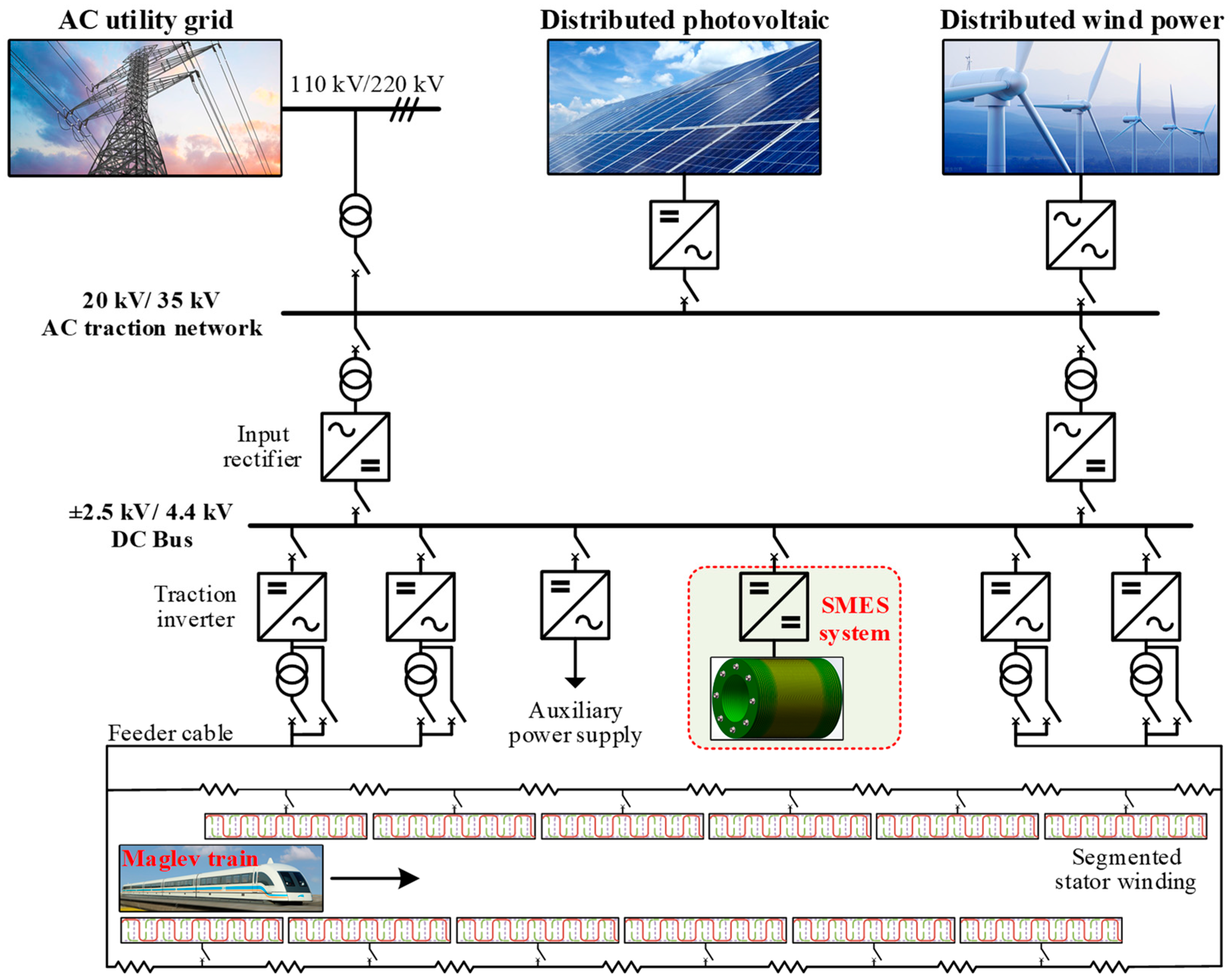
A novel scheme for a high-speed maglev integrated with distributed renewable energy and SMES systems was proposed. Distributed renewable energy sources can provide low-carbon power for high-speed maglev trains. The SMES system can solve the power quality problem of the traction power system and achieves a smooth transition during the transient switching between different working conditions.
(2)
A new multifunctional SMES compensation system was proposed. A power–voltage double-loop control strategy and a superconducting energy-storage magnet parameter design method were proposed to achieve the rapid compensation of high-speed maglev acceleration and regenerative braking, maintain voltage stability of the DC bus and traction network, and improve power supply quality and reliability.
The rest of the paper is organized as follows. Section 2 presents a novel scheme for the power system of the high-speed maglev using SMES and renewable energy sources. Section 3 introduces the compensation topology, control strategy, and working principle of the proposed SMES system, and presents the evaluation of the SMES’s capacity, which is suitable for compensating the traction system of maglev transportation. Section 4 establishes a traction power system model for high-speed maglevs and verifies the feasibility of compensating for voltage sag and stabilizing the interactive energy flow. Section 5 summarizes the characteristics and technical advantages of the SMES’s compensation for the maglev system.

2. Scheme of High-Speed Maglev Power System Using Superconducting Magnetic Energy Storage and Distributed Renewable Energy

The proposed framework using renewable energy and superconducting magnetic energy storage for the traction power system of a high-speed maglev is shown in Figure 1. The electricity consumed by the traction mainly comes from locally distributed renewable energy sources, such as photovoltaic and wind power generation systems. When the local renewable energy is insufficient, the power shortfall of the traction system is supplemented by the AC utility grid. Similarly, surplus renewable power can be fed into the AC utility grid, thereby reducing the energy consumption of the public grid and promoting the integration of renewable energy.
The traction power system of the maglev uses the classic topology [36]. The traction DC bus collects power from the traction power system at voltage levels of 20 kV or 35 kV stepping down to 4.4 kV DC. As eventually, the maglev train needs adjustable AC voltage, most power on the DC bus is again inverted to AC, which is then supplied to the stator windings through output transformers and feeding cables to drive the maglev train.
In particular, the SMES compensation system is connected to the DC bus, which utilizes the rapid response of SMES to maintain the stability of the bus voltage and achieve a smooth transition between the maglev and the traction power system under acceleration and braking operating conditions. Specifically, when distributed renewable energy systems have power fluctuations or the traction system has short-circuit faults, the DC bus voltage will have a transient drop, and the SMES can rapidly discharge electric energy to stabilize the DC bus voltage and keep on providing the maglev with high-quality power. Meanwhile, when the maglev is accelerating or decelerating, and the DC bus voltage has a sudden increase or decrease due to the sudden load change, the SMES can quickly compensate energy or absorbing energy to achieve smooth power transitions, which can further improve the power supply quality and stability of the traction system. Compared to super-capacitors, SMES has the unique advantages of virtually zero loss, ultra-high power density, and ultra-fast response. However, for high-voltage applications, super-capacitors with series and parallel connections have problems of huge volume, high complexity, and non-uniform current/voltage management [37,38].

3. Principle of SMES Power Compensation

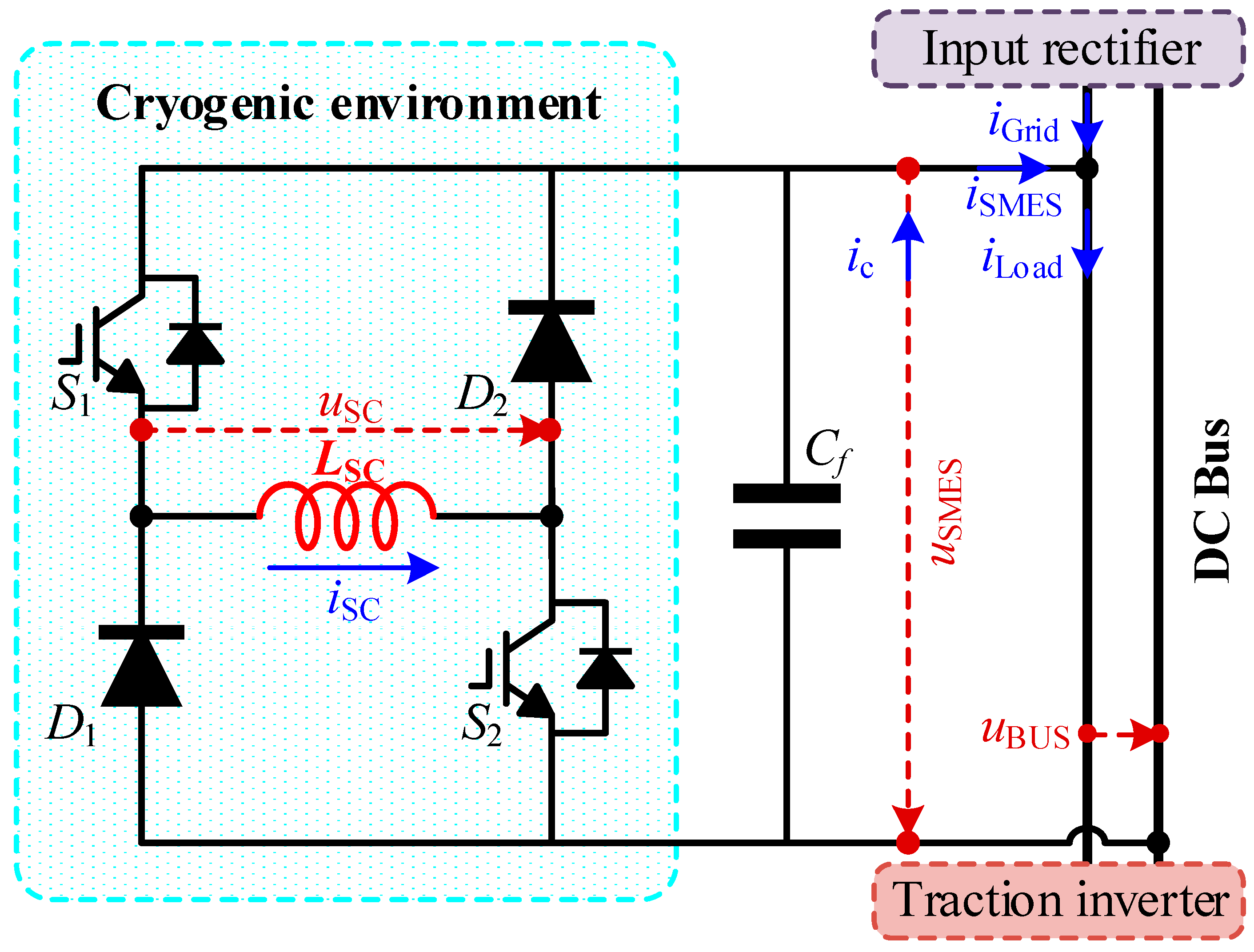
3.1. Topology and Operating Principle

Figure 2 shows the SMES-based compensation topology for the maglev traction power system, which consists of a superconducting magnet (LSC), an H-bridge converter, and an output filtering capacitor (Cf). These components are installed on the DC bus between the input rectifier and the output inverter. The H-bridge converter comprises a set of second-level diodes (D1, D2) and a set of power electronic switches (S1, S2) controlled by the same driving signal. During the on-time of S1 and S2, the current of the filtering capacitor charges the superconducting magnet through S1 and S2, absorbing energy from the DC bus. During the off-time of S1 and S2, the superconducting magnet discharges through the circuit formed by D1 and D2, providing current compensation to the DC bus. The continuous charging and discharging between the superconducting magnet and the filtering capacitor ultimately stabilizes the voltage of the DC bus. In particular, the superconducting magnet and the H-bridge converter are installed together in the same container and operate in a cryogenic environment (≤77 K). Based on previous work [39,40], the operating losses of power switches can be significantly reduced in cryogenic environments, and the low-temperature conditions can greatly enhance their overcurrent tolerance, which has already been applied in various fields such as electric aircraft and liquid air storage [41,42].
The SMES-based compensation circuit experiences two operational transients during each switching cycle, namely the charging transient ① and discharge transient ②, which correspond to the turned-on and turned-off time periods of the power electronic switches (S1, S2). According to Kirchhoff’s voltage law (KVL) and Kirchhoff’s current law (KCL), the voltage–current relationship of the compensation circuit in each switching cycle can be expressed by Equations (1) and (2).
u S M E S t L S C d i S C t d t R l i S C t = 0                                 0 t < D T S W , u S M E S t + L S C d i S C t d t R l i S C t u D = 0     D T S W t < T S W ,
i S M E S t + C f d u S M E S t d t i S C t = 0           0 t < D T S W , i S M E S t C f d u S M E S t d t i S C t = 0 D T S W t < T S W ,
where TSW and D are the cycle time and duty cycle ratio of the power electronic switch (S1, S2), respectively; uSMES and iSMES are the SMES output compensation voltage and current, respectively; iSC is the superconducting magnet current, and the superconducting magnet voltage uSC can be further expressed as LSCdiSC(t)/dt; Rl is the compensation circuit line internal resistance; and uD is the diode conduction voltage drop. Considering that the line internal resistance and diode conduction voltage drop are very low and can be neglected (compared to the 4.4 kV bus voltage), the output filter capacitor voltage is equal to the DC bus voltage. Equation (1) can be further simplified as
u S C t = u B U S t u B U S t
During each charging and discharging cycle, the operating current of the superconducting magnet can be considered constant, so the external output power of the SMES compensation system can be expressed by Equation (4):
P S M E S t = 1 2 D t u B U S t i S C t
The SMES-based compensation for the maglev traction power system has three working modes: the energy storage mode, energy charging mode, and energy release mode. The working mode is directly related to the duty cycle D of the power electronic switch. When the power absorbed by the SMES from the DC line (PSMES) is equal to the internal losses of the converter, the SMES system operates in the energy storage mode. As shown in Equation (4), the duty cycle of the power electronic switches is slightly higher than 0.5, and the operating current of the superconducting magnet remains stable. At this time, the compensation system is in steady-state operation.
As the duty cycle D increases to 1, the power absorbed by the SMES system from the DC bus gradually increases to its maximum, and the system operates in the charging mode with the operating current of the superconducting magnet rapidly increasing. Similarly, as the duty cycle D decreases to 0, the SMES system releases energy to compensate for the DC bus and gradually increases to its maximum. If the instantaneous surplus/deficit power on the DC bus exceeds the maximum capacity (uBUS*iSC) of the SMES compensation system, the DC bus voltage will experience sag or swell.
When the SMES-based power supply compensation system is in the transient operation process of the energy charging mode or energy discharging mode, the relationship between the compensation circuit output power (PSMES) and the superconducting magnet operating current (iSC) can be expressed by Equation (5):
i S C t = 2 0 t a P S M E S t d t L S C + I S C 0 2
where ta is the transient working time of the compensated circuit and ISC0 is the steady-state operating current of the superconducting magnet.

3.2. Control Strategy

The control strategy for the SMES compensation system is shown in Figure 3. It adopts a two-level control strategy consisting of a power loop and voltage loop according to the operating status of the maglev train. When the maglev train is at constant speed, the voltage loop control is employed. Firstly, the voltage deviation (ΔuSMES) is obtained by subtracting the actual voltage from the rated reference voltage of the DC bus, and then, the PI operation is performed to obtain the duty cycle deviation (ΔD). The output duty cycle (D) is obtained by adding a base duty cycle of 0.5. Finally, modulation is performed with a triangular carrier wave with a switching frequency of 20 kHz to obtain the drive signals for the power electronic switches S1 and S2. Voltage single-loop control is adopted to achieve faster response compensation under DC bus voltage transient disturbances (e.g., sag/swell).
When the maglev train is in the acceleration or braking state, the SMES compensation system adopts power–voltage dual-loop control to achieve a smooth transition for both the traction power and bus voltage. Firstly, the compensation power reference value (PSMES_ref) of the SMES system is calculated based on the real-time power transmission of the traction grid (PGrid) and the set acceleration or braking power of the train (PTrain_set). Then, the power deviation (ΔPSMES) is obtained by subtracting the real-time compensation power (PSMES) from the reference compensation power. Finally, the ΔPSMES is subjected to the PI operation to obtain the reference compensation voltage offset, which is then fed into the voltage inner-loop control after being superimposed with a reference voltage coefficient of 1.0.
The reference value of the compensated power of the SMES system in the above power loop control strategy is calculated by Equation (6):
P S M E S r e f ( t ) = P T r a i n _ s e t P G r i d t 0                 t = t 0 P S M E S t t + k t P t 0 < t t 0 + t e
where t0 is the initial moment of accelerating or braking of the maglev train, Δt is the time interval for updating the calculation of the reference value of the compensated power, and te is the artificially designed superconducting energy storage power compensation duration. ΔP is the base power increment, and k(t) is the coefficient of the power increment at different compensated moments:
k t = a + b = a + P T r a i n _ s e t P G r i d t P T r a i n _ s e t P G r i d t 0
where a is static power increment factor and b is dynamic power increment factor. In order to achieve the smooth transition of the SMES and the transmission power from the traction network, ΔP and k(t) should satisfy the following relationship:
t = t 0 t 0 + t e k t P = P G r i d t 0 P T r a i n _ s e t

3.3. SMES Capacity Estimation

The storage energy in the steady-state operation of SMES consists of two parts; one is the minimum operating energy used to maintain the SMES system trigger response compensation, and the other is the energy used to achieve the compensation of voltage sags or the acceleration of the maglev.
According to Equation (4), when the operating loss of the converter is ignored, the SMES system has a set power compensation capability, and the minimum operating current ISC_min of superconducting magnets needs to satisfy
I S C _ m i n P c o m p . u B U S = ρ u B U S i L o a d u B U S = ρ i L o a d
where Pcomp. is the maximum compensation power preset by the SMES system, and ρ is the ratio coefficient between the compensation power and the rated power of the DC bus. The maximum transient voltage drop needs to be within the effective compensation range. The second part of the energy used for transient power compensation is
Δ E S C 1 = ρ u B U S i L o a d t s a g Δ E S C 2 = t 0 t 0 + t e P S M E S t d t
where PSMES is the real-time compensated power of the SMES system and is equal to PSMES_ref. ΔESC and ΔESC2 are the minimum energy required to satisfy the compensation of voltage sags and maglev train acceleration, respectively, and the maximum values of the two are selected as the second part of the energy storage ΔESC. In particular, considering the actual operating losses of the converter, the steady-state operating current and energy storage of the SMES should increase properly, and the storage energy (ESC) and operation current (ISC) of the superconducting magnet should satisfy
E S C 1 2 L S C I S C _ m i n 2 + Δ E S C I S C = 2 E S C L S C
The maximum energy storage during operation depends on the maximum energy (ΔESC3) absorbed during the braking of the maglev train (for regenerative power), and the upper limit of its operating current should be less than the critical current of the magnet. ΔESC3 is calculated in the same way as ΔESC2, and the maximum operating current of superconducting magnets (ISC_max) can be expressed as
I S C _ m a x 2 E S C + Δ E S C 3 L S C

4. Case Study and Analysis

4.1. Case Configuration
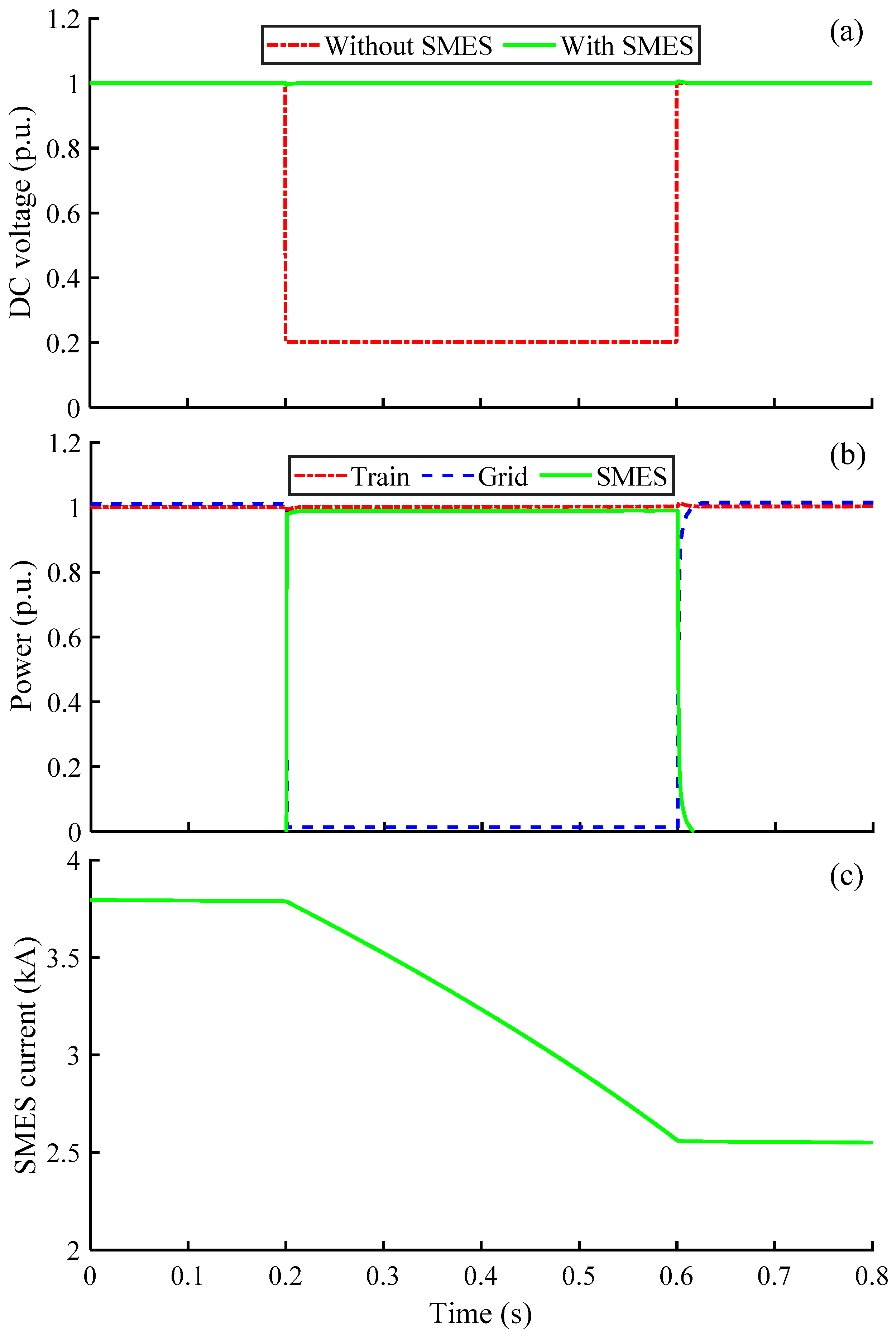
In order to verify the effectiveness and feasibility of the proposed SMES compensation system and its control strategy, as shown in Table 1, the SMES energy compensation system was built using MATLAB/SIMULINK R2021b. The AC traction system used a voltage level of 35 kV, which was converted to 4.4 kV for the DC bus. Considering the existing high-speed maglev with a top speed of 430 km/h, the distributed renewable energy was set at 10 MW, and the shortfall energy was supplied by the main grid. In order to mitigate the transient energy surge from high-speed maglevs to the traction system, the power commuting rate was limited to no larger than 100 MW/s. Three states of the high-speed maglev were set: low-speed starting up (5 MW), high-speed cruising (10 MW), and accelerating (20 MW). During regenerative braking, the linear motor became the generator and delivered the electric energy back to the traction system. The SMES system consisted of an HTS magnet and a power conversion module. The inductance of the HTS magnet was 1.028 H.
Based on Equations (9)–(12), taking into account a 10% converter operating loss and a 20% superconducting magnet energy storage margin, the SMES was designed to have 1.028 H/4.5 kA/10 MJ, with the initial operating current set at 3.8 kA. In particular, based on our existing design approach [45], a varying-axial-gap-structured solenoidal superconducting magnet (2.57 H/900 A/1.04 MJ) was designed [46]. As shown in Figure 4a, each superconducting magnet unit consists of 80 single pancake coils with 19 turns, coaxially mounted with a basic gap of 2 mm between the single pancake coils. Furthermore, the axial gaps of 11 single pancake coils at the ends of the superconducting magnet were optimized and adjusted. Along the direction of the magnet ends, the axial gaps of the single pancake coils increased sequentially by 1.89 mm. Compared to the superconducting magnet with fixed gaps, using the same length of superconducting tape (4813.42 m), the critical current and storage energy of the optimized superconducting magnet increased by 20.46% and 38.67%, respectively. Finally, ten superconducting magnet units were connected in series and parallel to form the whole SMES, as shown in Figure 4b.
Considering the distributed renewable energy integrated into the traction system of maglevs, to further test the energy compensation performance of the SMES system, three case studies were performed.
Case 1: At t = 0.2–0.6 s, the renewable energy generation had severe problems or the traction system had short-circuit faults, and there was a deep voltage drop (80%) in the DC bus, which was achieved by adding huge resistance to the DC bus in the simulation. This case tested whether the SMES system was able to compensate the transient voltage disturbance and improve power supply quality for the maglev.
Case 2: At = 0.2 s, the maglev started to accelerate, and the energy demand suddenly increased from 5 MW (0.5 p.u.) to 20 MW (2.0 p.u.), which was achieved by adding a non-linear power increase of (MW) to the load. This case tested whether the SMES system was able to the stabilize the DC bus of the traction system when the maglev needed more energy to accelerate.
Case 3: At = 0.2 s, the maglev started to decelerate, and the regenerative braking generated 10 MW (1.0 p.u.) electric power and delivered it back to the traction system, which was achieved by adding a time-controlled power source sending energy back. This case tested whether the SMES system was able to quickly stabilize the DC bus by absorbing electric energy from the maglev’s regenerative braking.

4.2. Voltage Sags

Considering the voltage disturbance caused by the renewable energy sources, such as photovoltaic and wind power, connected to the traction network, a test was conducted to simulate a voltage sag with an amplitude of 80% on the DC bus. As shown in Figure 5, the DC bus voltage dropped from the rated value of 1.0 p.u. to 0.2 p.u. at the moment of 0.2 s, and continued to be faulted for 400 ms. It can be observed that, by using no-delay SMES compensation, the DC bus voltage was effectively stabilized, with only a slight fluctuation of below 0.6% at the occurrence and termination of the fault, and it quickly stabilized to the rated value within 10 ms. The DC bus voltage ripple under SMES compensation was only 1.5 V (about 0.03%). During the occurrence of the voltage sag fault, the SMES provided almost the entire power demand of the high-speed operation of the maglev train. The operating current of the superconducting magnet decreased from 3.8 kA to 2.5 kA, releasing 4.21 MJ of energy to maintain the normal operation of the maglev train, which successfully alleviated the pressure on the traction network. After the fault was cleared, the SMES system was able to absorb power from the traction network and automatically restore it to the rated operating current.

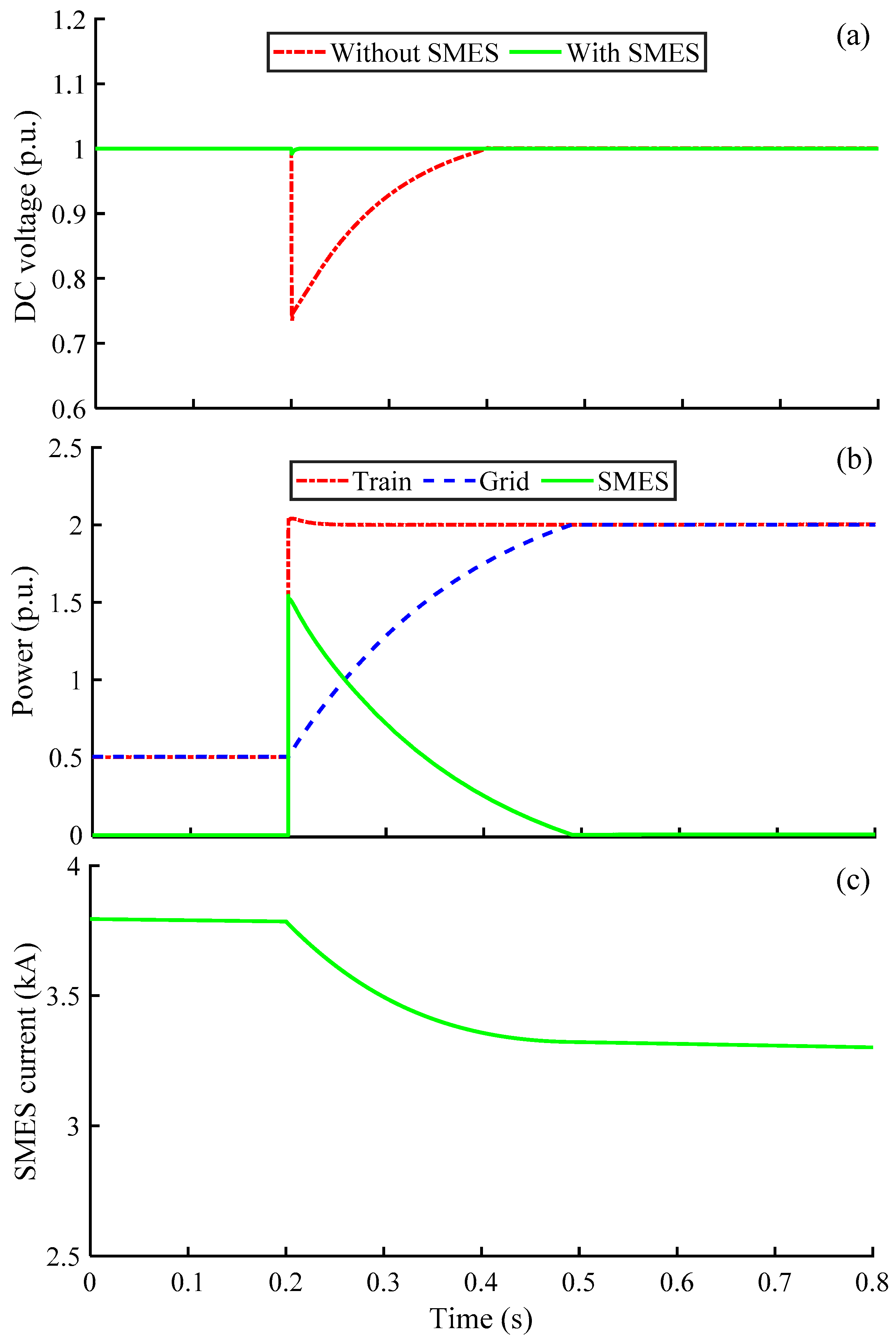
4.3. Train Acceleration

Figure 6 presents the power output of the traction system and SMES during the acceleration of the maglev. At the moment of 0.2 s, the maglev train started to accelerate, and the load power of the linear traction motor instantaneously increased from 0.5 p.u. to 2.0 p.u. In the absence of SMES, the DC bus voltage would cause a voltage sag of 0.25 p.u., resulting in insufficient power supply to the linear traction motor, which could not achieve the pre-set acceleration speed. With SMES compensation, the SMES was able to instantaneously output 1.5 p.u. of the required acceleration power. The DC bus voltage only showed a voltage fluctuation of 0.8% at the time of SMES compensation, and recovered to the rated voltage within 10 ms. According to the proposed power–voltage dual-loop control strategy, the compensation power of the SMES system gradually decreased to zero within 300 ms, allowing the traction grid load power to slowly increase to 20 MW. This effectively mitigated the sudden load increase in the traction grid during the acceleration phase of the maglev.

4.4. Regenerative Braking

Maglev trains running with high speeds carry a large amount of kinetic energy. Under normal deceleration, the regenerative braking system is used to convert the kinetic energy into electrical energy, which is then fed back to the traction grid through power electronic devices. As shown in Figure 7a, the linear traction motor of the maglev train output an equal amount of reverse power during braking, which would cause the voltage to rise significantly if all the power was directly delivered back to the DC bus. This, in turn, increased the voltage and current stress on the power electronic devices, leading to possible damage to sensitive power electronic components [20]. In practical operation, a maglev train connects a braking resistor to the DC bus during deceleration, rapidly dissipating the excess regenerative power output to stabilize the DC bus voltage [47]. However, this results in a significant waste of the maglev’s kinetic energy.
The proposed SMES system was able to effectively absorb a large amount of excess energy during the braking of the maglev with high speed, and also stably keep the DC bus voltage. As shown in Figure 7, during 0.2 s braking, the SMES system was able to absorb all the power (1.0 p.u.) re-generated by the linear traction motor, alleviating the voltage impact on the DC bus voltage caused by the braking of the maglev. After 0.42 s, according to the control strategy, the SMES’s absorbed power gradually dropped to zero, and the traction network’s absorbed power steadily increased to the maglev train’s regenerative braking power. Compared to the uncompensated condition, the SMES system reduced the temporary voltage of the DC bus from 2.9 p.u. to 1.04 p.u., which was within the allowable range of voltage fluctuation (10%). During 220 ms of the regenerative braking transition, the SMES absorbed 1.05 MJ of electrical energy from the maglev, and the operating current increased from 3.8 kA to 4.06 kA. This case study validated the effectiveness of the proposed SMES system and its control strategy, achieving stable supply voltage and smooth power transition.

5. Conclusions

In this paper, a novel scheme was proposed for high-speed maglevs using superconducting magnetic energy storage and distributed renewable energy sources. The SMES compensation system was used to enhance the power quality of the maglev and ensure stable power supply during operation. A power system model for a 20 MW maglev with a 10.4 MJ SMES was established, and the feasibility and superiority of the SMES compensation scheme were verified. The overall novelties and contributions can be summarized as follows:
(1)
A new scheme for the maglev traction power system: local distributed renewable sources were used to provide low-carbon energy for maglevs, thereby reducing the power consumption from the utility grid, and the SMES system was integrated to improve the overall power quality.
(2)
Improvement in the power quality of maglevs: the SMES system provided rapid compensation for the traction power system, addressing the voltage sags caused by the integration of fluctuating renewable energy sources into the traction power system, ensuring high-quality power supply for the maglevs. When a voltage sag with a depth of 80% occurred in the 10 MW traction power system, the SMES system quickly stabilized the DC bus voltage within 10 ms, with voltage fluctuations of less than 0.6%.
(3)
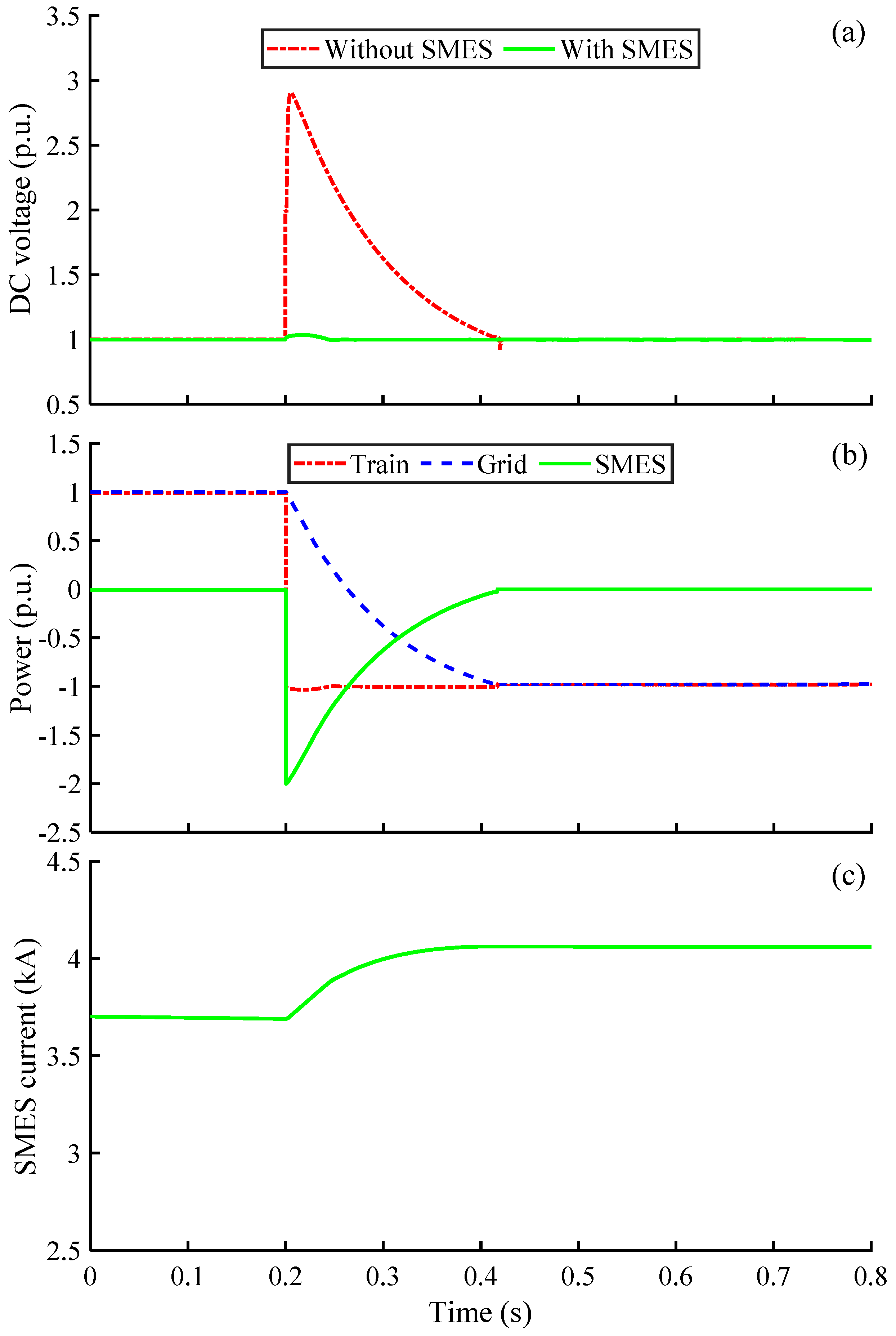
The smooth transition of interactive energy flow between the traction power system and the maglev: By using the proposed power–voltage dual-loop control, SMES can actively respond to the power demand of maglev trains during acceleration and braking conditions by rapidly releasing and absorbing energy, avoiding transient power impacts on the traction grid, and achieving smooth regenerative braking. During the transient process of maglev acceleration, the SMES system quickly responded to the output of a sudden increase of 15 MW power required for train acceleration within 10 ms, and stabilized the DC bus with fluctuations of less than 0.8%.
To conclude, the proposed SMES power compensation system is expected to become a promising solution for high-speed maglevs and other railway transportation to solve power quality issues with the integration of renewable energy.

Author Contributions

Conceptualization, B.S., L.F. and X.C.; methodology, L.F. and M.Z.; software, M.Z. and Y.C.; validation, L.F., M.Z. and Y.C.; formal analysis, M.Z. and B.S.; investigation, L.F., Y.C. and X.C.; data curation, M.Z. and X.C.; writing—original draft preparation, L.F., M.Z., X.C. and B.S.; writing—review and editing, L.F., M.Z., X.C. and B.S.; visualization, L.F. and M.Z.; supervision, X.C. and B.S.; project administration, X.C. and B.S. All authors have read and agreed to the published version of the manuscript.

Funding

This research was supported in part by the Young Elite Scientists Sponsorship Program by CAST (Grant No. 2023QNRC001).

Data Availability Statement

The data presented in this study are available on request from the corresponding author.

Conflicts of Interest

The authors declare no conflicts of interest.

Abbreviations

Abbreviations
ACalternating current
DCdirect current
DFIGdoubly fed induction generator
DVRdynamic voltage restorer
KCLKirchhoff’s current law
KVLKirchhoff’s voltage law
SMESsuperconducting magnetic energy storage
Nomenclature
astatic power increment factor
bdynamic power increment factor
Dduty cycle ratio of the power electronic switch
ESCstorage energy of the superconducting magnet
ISCoperation current of the superconducting magnet
iSCsuperconducting magnet current
iSCsuperconducting magnet operating current
ISC_maxmaximum operating current of superconducting magnets
ISC_minminimum operating current of superconducting magnets
ISC0steady-state operating current of the superconducting magnet
iSMESSMES output compensation current
k(t)coefficient of the power increment at different compensated moments
Pcomp.maximum compensation power preset by the SMES system
PGridreal-time power transmission of the traction grid
PSMEScompensation circuit output power
PSMES_refcompensation power reference value
PTrain_setset acceleration or braking power of the train
Rlcompensation circuit line internal resistance
t0initial moment of accelerating or braking of the maglev train
tatransient working time of the compensated circuit
teartificially designed superconducting energy storage power compensation duration
TSWcycle time of the power electronic switch
uDdiode conduction voltage drop
uSCsuperconducting magnet voltage
uSMESSMES output compensation voltage
ΔDduty cycle deviation
ΔESCminimum energy required to satisfy the compensation of voltage sags
ΔESC2minimum energy required to satisfy the compensation of maglev train acceleration
ΔESC3maximum energy absorbed during the braking of the maglev train
ΔPbase power increment
ΔPSMESpower deviation
Δttime interval for updating the calculation of the reference value of the compensated power
ΔuSMESvoltage deviation
ρratio coefficient between the compensation power and the rated power of the DC bus

References

  1. Li, F.; Sun, Y.; Xu, J.; He, Z.; Lin, G. Control methods for levitation system of EMS-type maglev vehicles: An overview. Energies 2023, 16, 2995. [Google Scholar] [CrossRef]
  2. Beauloye, L.; Dehez, B. Permanent Magnet Electrodynamic Suspensions Applied to MAGLEV Transportation Systems: A Review. IEEE Trans. Transp. Electrif. 2023, 9, 748–758. [Google Scholar] [CrossRef]
  3. Zuo, J.; Dong, L.; Yang, F.; Guo, Z.; Wang, T.; Zuo, L. Energy harvesting solutions for railway transportation: A comprehensive review. Renew. Energy 2023, 202, 56–87. [Google Scholar] [CrossRef]
  4. Mitrofanov, S.V.; Kiryanova, N.G.; Gorlova, A.M. Stationary hybrid renewable energy systems for railway electrification: A review. Energies 2021, 14, 5946. [Google Scholar] [CrossRef]
  5. Teng, J.; Li, L.; Jiang, Y.; Shi, R. A review of clean energy exploitation for railway transportation systems and its enlightenment to China. Sustainability 2022, 14, 10740. [Google Scholar] [CrossRef]
  6. Chen, Y.; Fu, L.; Chen, X.; Jiang, S.; Chen, X.; Xu, J.; Shen, B. Ultra-low electrical loss superconducting cables for railway transportation: Technical, economic, and environmental analysis. J. Clean. Prod. 2024, 445, 141310. [Google Scholar] [CrossRef]
  7. Shavolkin, O.; Shvedchykova, I.; Gerlici, J.; Kravchenko, K.; Pribilinec, F. Use of hybrid photovoltaic systems with a storage battery for the remote objects of railway transport infrastructure. Energies 2022, 15, 4883. [Google Scholar] [CrossRef]
  8. Zhong, Z.; Zhang, Y.; Shen, H.; Li, X. Optimal planning of distributed photovoltaic generation for the traction power supply system of high-speed railway. J. Clean. Prod. 2020, 263, 121394. [Google Scholar] [CrossRef]
  9. Kim, H.; Ku, J.; Kim, S.-M.; Park, H.-D. A new GIS-based algorithm to estimate photovoltaic potential of solar train: Case study in Gyeongbu line, Korea. Renew. Energy 2022, 190, 713–729. [Google Scholar] [CrossRef]
  10. Jia, L.; Ma, J.; Cheng, P.; Liu, Y. A perspective on solar energy-powered road and rail transportation in China. CSEE J. Power Energy Syst. 2020, 6, 760–771. [Google Scholar] [CrossRef]
  11. Chen, X.; Pang, Z.; Zhang, M.; Jiang, S.; Feng, J.; Shen, B. Techno-economic study of a 100-MW-class multi-energy vehicle charging/refueling station: Using 100% renewable, liquid hydrogen, and superconductor technologies. Energy Convers. Manag. 2023, 276, 116463. [Google Scholar] [CrossRef]
  12. Chen, Z.; Jiang, M.; Qi, L.; Wei, W.; Yu, Z.; Wei, W.; Yu, X.; Yan, J. Using existing infrastructures of high-speed railways for photovoltaic electricity generation. Resour. Conserv. Recycl. 2021, 178, 106091. [Google Scholar] [CrossRef]
  13. Li, X.; Zhu, C.; Liu, Y. Traction power supply system of China high-speed railway under low-carbon target: Form evolution and operation control. Electr. Power Syst. Res. 2023, 223, 109682. [Google Scholar] [CrossRef]
  14. Ding, F.; Yang, J.; Zhou, Z. Economic profits and carbon reduction potential of photovoltaic power generation for China’s high-speed railway infrastructure. Renew. Sustain. Energy Rev. 2023, 178, 113272. [Google Scholar] [CrossRef]
  15. Wang, H.; Yi, M.; Zeng, X.; Zhang, T.; Luo, D.; Zhang, Z. A hybrid, self-adapting drag-lift conversion wind energy harvesting system for railway turnout monitoring on the Tibetan Plateau. Sustain. Energy Technol. Assess. 2021, 46, 101262. [Google Scholar] [CrossRef]
  16. Belay Kebede, A.; Worku, G.B. A research on regenerative braking energy recovery: A case of addis ababa light rail transit. eTransportation 2021, 8, 100117. [Google Scholar] [CrossRef]
  17. Böhm, M.; Fernández Del Rey, A.; Pagenkopf, J.; Varela, M.; Herwartz-Polster, S.; Nieto Calderón, B. Review and comparison of worldwide hydrogen activities in the rail sector with special focus on on-board storage and refueling technologies. Int. J. Hydrogen Energy 2022, 47, 38003–38017. [Google Scholar] [CrossRef]
  18. Cheng, P.; Kong, H.; Ma, J.; Jia, L. Overview of resilient traction power supply systems in railways with interconnected microgrid. CSEE J. Power Energy Syst. 2021, 7, 1122–1132. [Google Scholar] [CrossRef]
  19. BADE, S.; Kulkarni, V. Analysis of railway traction power system using renewable energy: A review. In Proceedings of the 2018 International Conference on Computation of Power, Energy, Information and Communication (ICCPEIC), Chennai, India, 28–29 March 2018. [Google Scholar] [CrossRef]
  20. Dong, H.; Tian, Z.; Spencer, J.; Fletcher, D.; Hajiabady, S. Coordinated control strategy of railway multisource traction system with energy storage and renewable energy. IEEE Trans. Intell. Transp. Syst. 2023, 24, 15702–15713. [Google Scholar] [CrossRef]
  21. Chen, X.; Yue, J.; Fu, L.; Zhang, M.; Tang, M.; Feng, J.; Shen, B. Green hydrogen production and liquefaction using offshore wind power, liquid air, and LNG cold energy. J. Clean. Prod. 2023, 423, 138653. [Google Scholar] [CrossRef]
  22. Li, M.; Zheng, J.; Sheng, J.; Cheng, Y.; Hong, Z.; Ye, H.; Wang, X.; Liu, X.; Liu, H. Research on a novel HTS double pancake coil based on CORC: Used for kA-level SMES of accelerator. Supercond. Sci. Technol. 2022, 35, 125001. [Google Scholar] [CrossRef]
  23. Chen, X.; Xie, Q.; Bian, X.; Shen, B. Energy-saving superconducting magnetic energy storage (SMES) based interline DC dynamic voltage restorer. CSEE J. Power Energy Syst. 2022, 8, 238–248. [Google Scholar] [CrossRef]
  24. Jiao, F.; Tang, Y.; Xi, T.; Zhou, S.; Ge, T.; He, Q.; Ren, L.; He, J.; Li, J. Electromagnetic and thermal design of a conduction-cooling 150 kJ/100 kW hybrid SMES system. IEEE Trans. Appl. Supercond. 2012, 23, 5701404. [Google Scholar] [CrossRef]
  25. Xu, Y.; Tang, Y.; Ren, L.; Shi, J.; Li, J.; Song, M.; Cao, K.; Wang, D.; He, J.; Zhang, R.; et al. Numerical simulation of coupled heat transfer, stress, and electromagnetic properties in an SMES magnet. IEEE Trans. Appl. Supercond. 2013, 24, 4901005. [Google Scholar] [CrossRef]
  26. Noguchi, S.; Inaba, Y.; Igarashi, H. An optimal configuration design method for HTS-SMES coils taking account of thermal and electromagnetic characteristics. IEEE Trans. Appl. Supercond. 2008, 18, 762–765. [Google Scholar] [CrossRef]
  27. Zhang, J.; Dai, S.; Wang, Z.; Zhang, D.; Song, N.; Gao, Z.; Zhang, F.; Xu, X.; Zhu, Z.; Zhang, G.; et al. The electromagnetic analysis and structural design of a 1 MJ HTS magnet for SMES. IEEE Trans. Appl. Supercond. 2011, 21, 1344–1347. [Google Scholar] [CrossRef]
  28. Kumar, A.; Jeyan, J.M.L.; Agarwal, A. Electromagnetic analysis on 2.5 MJ high temperature superconducting magnetic energy storage (SMES) coil to be used in uninterruptible power applications. Mater. Today Proc. 2020, 21, 1755–1762. [Google Scholar] [CrossRef]
  29. Xu, Y.; Ren, L.; Zhang, Z.; Tang, Y.; Shi, J.; Xu, C.; Li, J.; Pu, D.; Wang, Z.; Liu, H.; et al. Analysis of the loss and thermal characteristics of a SMES (Superconducting Magnetic Energy Storage) magnet with three practical operating conditions. Energy 2018, 143, 372–384. [Google Scholar] [CrossRef]
  30. Zhao, Z.; Wang, Y.; Gao, Y.; Yang, Z.; Li, Z.; Pi, W. Mechanical characterization of a 10-MJ HTS SMES magnet wound by quasi-isotropic strands and directly stacked tape conductors. Superconductivity 2023, 5, 100042. [Google Scholar] [CrossRef]
  31. Ali, M.H.; Wu, B.; Dougal, R.A. An overview of smes applications in power and energy systems. IEEE Trans. Sustain. Energy 2010, 1, 38–47. [Google Scholar] [CrossRef]
  32. Papageorgiou, P.G.; Oureilidis, K.O.; Christoforidis, G.C. A systematic review of hybrid superconducting magnetic/battery energy storage systems: Applications, control strategies, benefits, limitations and future prospects. Renew. Sustain. Energy Rev. 2023, 183, 113436. [Google Scholar] [CrossRef]
  33. Yang, R.; Jin, J.; Zhou, Q.; Mu, S.; Abu-Siada, A. Superconducting magnetic energy storage based DC unified power quality conditioner with advanced dual control for DC-DFIG. J. Mod. Power Syst. Clean Energy 2022, 10, 1385–1400. [Google Scholar] [CrossRef]
  34. Babu, V.; Ahmed, K.S.; Shuaib, Y.M.; Manikandan, M. Power quality enhancement using dynamic voltage restorer (DVR)-based predictive space vector transformation (PSVT) with proportional resonant (PR)-controller. IEEE Access 2021, 9, 155380–155392. [Google Scholar] [CrossRef]
  35. Suzuki, S.; Baba, J.; Shutoh, K.; Masada, E. Effective application of superconducting magnetic energy storage (SMES) to load leveling for high speed transportation system. IEEE Trans. Appl. Supercond. 2004, 14, 713–716. [Google Scholar] [CrossRef]
  36. Zou, Z.; Zheng, M.; Lu, Q. Modeling and simulation of traction power supply system for high-speed maglev train. World Electr. Veh. J. 2022, 13, 82. [Google Scholar] [CrossRef]
  37. Cui, G.; Luo, L.; Liang, C.; Hu, S.; Li, Y.; Cao, Y.; Xie, B.; Xu, J.; Zhang, Z.; Liu, Y.; et al. Supercapacitor Integrated Railway Static Power Conditioner for Regenerative Braking Energy Recycling and Power Quality Improvement of High-Speed Railway System. IEEE Trans. Transp. Electrif. 2019, 5, 702–714. [Google Scholar] [CrossRef]
  38. Kaleybar, H.J.; Brenna, M.; Foiadelli, F.; Fazel, S.S.; Zaninelli, D. Power Quality Phenomena in Electric Railway Power Supply Systems: An Exhaustive Framework and Classification. Energies 2020, 13, 6662. [Google Scholar] [CrossRef]
  39. Gui, H.; Chen, R.; Niu, J.; Zhang, Z.; Tolbert, L.M.; Wang, F.; Blalock, B.J.; Costinett, D.; Choi, B.B. Review of power electronics components at cryogenic temperatures. IEEE Trans. Power Electron. 2020, 35, 5144–5156. [Google Scholar] [CrossRef] [PubMed]
  40. Chen, R.; Wang, F.F. SiC and GaN devices with cryogenic cooling. IEEE Open J. Power Electron. 2021, 2, 315–326. [Google Scholar] [CrossRef]
  41. Chen, X.Y.; Chen, Y.; Fu, L.; Zhang, Z.Y.; Tang, M.G.; Feng, J.; Jiang, S.; Lei, Y.; Zhang, D.H.; Shen, B.Y. Photovoltaic-driven liquid air energy storage system for combined cooling, heating and power towards zero-energy buildings. Energy Convers. Manag. 2024, 299, 117959. [Google Scholar] [CrossRef]
  42. Gui, H.; Zhang, Z.; Chen, R.; Ren, R.; Niu, J.; Li, H.; Dong, Z.; Timms, C.; Wang, F.; Tolbert, L.M.; et al. Development of high-power high switching frequency cryogenically cooled inverter for aircraft applications. IEEE Trans. Power Electron. 2020, 35, 5670–5682. [Google Scholar] [CrossRef]
  43. Janic, M. Estimation of direct energy consumption and CO2 emission by high speed rail, transrapid maglev and hyperloop passenger transport systems. Int. J. Sustain. Transp. 2021, 15, 696–717. [Google Scholar] [CrossRef]
  44. Fritz, E.; Eckert, F.; Blow, L.; Kircher, R.; Witt, M. Energy consumption of track-based high-speed trains: Maglev systems in comparison with wheel-rail systems. Transp. Syst. Technol. 2018, 4, 134–155. [Google Scholar] [CrossRef]
  45. Chen, X.; Pang, Z.; Gou, H.; Xie, Q.; Zhao, R.; Shi, Z.; Shen, B. Intelligent design of large-size HTS magnets for SMES and high-field applications: Using a self-programmed GUI tool. Supercond. Sci. Technol. 2021, 34, 095008. [Google Scholar] [CrossRef]
  46. Chen, X.; Zhang, M.; Jiang, S.; Gou, H.; Zhou, P.; Yang, R.; Shen, B. Energy reliability enhancement of a data center/wind hybrid DC network using superconducting magnetic energy storage. Energy 2023, 263, 125622. [Google Scholar] [CrossRef]
  47. Ceraolo, M.; Lutzemberger, G.; Meli, E.; Pugi, L.; Rindi, A.; Pancari, G. Energy storage systems to exploit regenerative braking in DC railway systems: Different approaches to improve efficiency of modern high-speed trains. J. Energy Storage 2018, 16, 269–279. [Google Scholar] [CrossRef]
Figure 1. Novel scheme of high-speed maglev power system using superconducting magnetic energy storage and distributed renewable energy.
Electronics 13 00979 g001
Figure 2. SMES-based compensation topology for the maglev traction power system.
Electronics 13 00979 g002
Figure 3. Control strategy of the SMES compensation system.
Electronics 13 00979 g003
Figure 4. Structures of the SMES: (a) varying-axial-gap structure; (b) connections of each unit.
Electronics 13 00979 g004
Figure 5. Compensation performance of SMES against voltage sag: (a) DC bus voltage; (b) power of maglev trains, traction grids, and SMES systems; (c) SMES operating currents.
Electronics 13 00979 g005
Figure 6. Compensation performance of SMES with maglev acceleration: (a) DC bus voltage; (b) power of maglev trains, traction grids, and SMES systems; (c) SMES operating currents.
Electronics 13 00979 g006
Figure 7. Compensation performance of SMES against regenerative braking of maglev trains: (a) DC bus voltage; (b) power of maglev trains, traction grids, and SMES systems; (c) SMES operating currents.
Electronics 13 00979 g007
Table 1. Parameters of the maglev traction power system.
Title 1ParametersValue
Traction
network
Voltage35 kV
DC bus voltage4.4 kV (1.0 p.u.)
Maglev train [43,44]Carriages per vehicle/train6
Gross (total) mass382–399 tons
Capacity472–696 seats
Typical average cruising speed430 km/h
Low-speed power5 MW (0.5 p.u.)
High-speed cruising power10 MW (1.0 p.u.)
Acceleration power20 MW (2.0 p.u.)
SMES systemInductance1.028 H
Energy storage10.4 MJ
Critical current4.5 kA
Operating current3.8 kA
Converter power4.4 kV/25 MW
Disclaimer/Publisher’s Note: The statements, opinions and data contained in all publications are solely those of the individual author(s) and contributor(s) and not of MDPI and/or the editor(s). MDPI and/or the editor(s) disclaim responsibility for any injury to people or property resulting from any ideas, methods, instructions or products referred to in the content.

