Article

Dynamic Path Planning Based on 3D Cloud Recognition for an Assistive Bathing Robot

1
Institution of Rehabilitation Engineering and Technology, University of Shanghai for Science and Technology, No. 580, Jungong Road, Yangpu District, Shanghai 200093, China
2
Shanghai Engineering Research Center of Assistive Devices, Shanghai 200093, China
3
Key Laboratory of Neural-Functional Information and Rehabilitation Engineering of the Ministry of Civil Affairs, Shanghai 200093, China
*
Author to whom correspondence should be addressed.
Electronics 2024, 13(7), 1170; https://doi.org/10.3390/electronics13071170
Submission received: 4 February 2024 / Revised: 15 March 2024 / Accepted: 18 March 2024 / Published: 22 March 2024

Abstract

:
Assistive bathing robots have become a popular point due to their metrics, such as a humanoid working approach in the solution of elder care. However, the abilities of dynamic recognition and path planning are the key to obtain the advantages. This paper proposes a novel approach to recognize and track the dynamical human back, and path planning on it via a 3D point cloud. Firstly, the human back geometric features are recognized through coarse-to-fine alignment. The Intrinsic Shape Signature (ISS) algorithm combined with the Fast Point Feature Histogram (FPFH) and the Sample Consensus Initial Alignment (SAC-IA) algorithm are adopted to complete the coarse alignment, and the Iterative Closest Point (ICP) algorithm is applied to the fine alignment to improve the accuracy of recognition. Then, the dynamic transformation matrix between the contiguous recognized back is deduced based on spatial motion between two adjacent recognized back point clouds. The path can be planned on the tracked human back. Finally, a set of testing experiments are conducted to verify the proposed algorithm. The results show that the running time is reduced by 66.18% and 96.29% compared with the other two common algorithms, respectively.

1. Introduction

The increasingly serious social aging [1] has drawn attention from all walks of life to products that assist the elderly and the disabled. In recent years, various types of robots have been developed for elderly care, such as bath robots [2], moxibustion robots [3], and massage robots [4]. The issue of safety and comfort for these robots during their work is crucial, since they must use their robotic arms to imitate human hands to work on the user’s back. Dynamic path planning for bathing is a challenging task because the robot must recognize localization and perform dynamic tracking and path planning during human movements.
The majority of available studies on back recognition are static. Chen H et al. [5] recognized the back by pasting a large number of artificial markers on the body back, which is simple and rapid, but with limited application scenarios. K.C. Jones et al. [6] designed a massage robot that recognizes the back by directly inputting the coordinates of the user’s shoulder and waist points. However, it is unable to adapt to the individual differences of users with different body sizes. Meanwhile, the previously inputted coordinates cannot correspond to the user’s body parts with the movement of the user during the massage. In practical situations, users inevitably change their sitting posture due to breathing or other factors. Thus, the robot needs to quickly acquire three-dimensional information about the human body surface to recognize the body’s back region in different postures.
Visual tracking based on vision algorithms can detect and label relevant features of the body for tracking [7,8]. Point cloud alignment is a typical class of posture estimation algorithms that is divided into two stages: coarse alignment (CA) and fine alignment (FA). The common alignment algorithms are as follows: RANSAC [9], 4PCS [10], PCA [11], etc. The common feature descriptors in point clouds are PFH [12], FPFH [13], VFH [14], and SHOT [15]. X. Gong et al. [16] completed the CA by combining the point cloud VFH features with SAC-IA, then used the ICP algorithm to optimize the object’s posture. B. Shen et al. [17] realized a point cloud CA via FPFH and performed several iterations of the ICP algorithm to improve the alignment accuracy.
Meanwhile, it is necessary to plan the robot’s motion path to ensure that the robot works safely and efficiently. Path planning algorithms based on 3D point clouds have been widely used in robots working on human skin surfaces. Y. Hu et al. [18] designed different massage trajectories for forehead and mid-cheeks by capturing three-dimensional information of facial contours. X. Zhang et al. [19] captured the surface point cloud data of a breast model using a binocular camera and fitted the scan path via the NURBS curves. R.C. Luo et al. [20] estimated the coronal and sagittal planes of the human body through RANSAC, mapped the planar trajectories into a spatial point cloud, then generated massage trajectories. The above recognition algorithms are complex, and the amount of computation for trajectory generation is too cumbersome. In practice, the human body does not remain completely still, so the robot needs to quickly acquire the real-time position of the human body to improve the efficiency of work and protect the user’s safety.
This paper proposes a dynamic back tracking and bathing path planning algorithm, respectively, for the situation when the human back changes posture to improve the ability of interaction of the assistive bathing robot. The main contributions of this paper are as follows:
  • The human body point cloud is rapidly acquired based on the scene information collected by the depth camera in this paper, which solves the problem of a large amount of collected scene data and redundant point clouds.
  • This paper recognized the back region using the back geometric features in the human body point cloud, which was without RGB information and evident texture. An effective segmentation method of the back region is proposed for users with different body types in different postures during moving.
  • This paper proposes a point cloud coarse-to-fine alignment algorithm that incorporates a spatial motion transformation matrix to achieve human back tracking.
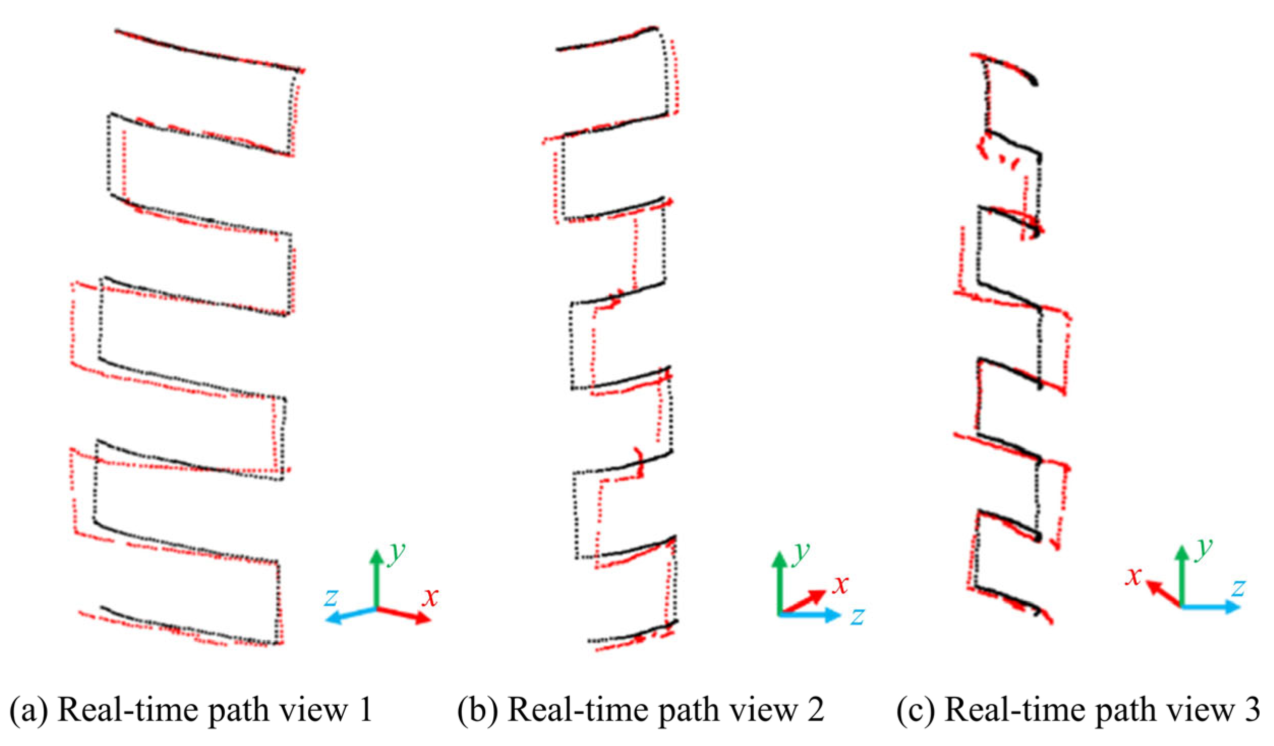
  • We provided a method for acquiring bathing paths and realized dynamic path planning by combining the outcomes of back tracking. The issue of the robot being unable to alter the bathing path in time due to the user’s involuntary movement during the bathing process has been resolved.
  • The proposed algorithm is compared with the 3Dcs-ICP algorithm and standard coarse–fine alignment algorithm for back tracking experiments, respectively, and the comprehensive performance of the algorithm is illustrated in terms of evaluation metrics such as recognition speed and accuracy.
The remainder of the paper is organized as follows: Section 2 and Section 3 introduce the principle of the proposed algorithms. Section 4 presents the experimental platform construction and results, respectively. Finally, the conclusion is drawn in Section 5.

2. Dynamic Tracking Algorithm

Users usually involuntarily adjust their postures due to breathing or other factors during the bathing process. The original bathing paths should be adjusted accordingly with the change in back postures, thus improving users’ comfort. Meanwhile, the object of the assistive bathing robot is oriented to the semi-disabled elderly, and the whole bathing process is performed on a chair. Therefore, the chair can be regarded as the fixed coordinate system O C X C Y C Z C shown in Figure 1 to calculate the transformation matrix of a point on the human back point cloud during the movement.
This paper proposes a dynamic tracking algorithm to solve the problem of involuntary random motion of the human body during the working process of the assistive bathing robot; the human back space motion transformation matrix is obtained through registration results from two adjacent frames of point clouds. The specific process is shown in Figure 2.
Firstly, the number of point clouds is reduced by sampling under VoxelGrid filter; secondly, the two-frame point cloud’s approximate rotational translation matrix is computed from the coarse alignment after extracting the key points; finally, the exact matrix is obtained by iterating from the fine alignment.

2.1. Recognition of the Human Back

As shown in Figure 3a, the point cloud without RGB information collected by the depth camera includes a large amount of redundant information, such as walls and floors. It is necessary to preprocess the point cloud to improve the algorithm efficiency, which is divided into three parts, as illustrated in Figure 3b. Then, the human body point cloud is obtained as shown in Figure 3c.
Firstly, many point clouds of the walls are removed by a passthrough filter. The point cloud P 2 , which contains the human body region and the seat region, can be obtained as
P 2 = x 1 < x i < x 2 z 1 < z i < z 2 ,   p i P 1
where P 1 = p i | p i R 3 , i = 1 , 2 , , n denotes the scene point cloud captured by the camera, p i denotes any point in the point cloud, and x 1 ,   x 2 and z 1 ,   z 2 are the threshold value in the x - and z - directions, respectively.
Secondly, the statistical filter of the point cloud is required to minimize the effect of outlier point clouds. The point cloud P 3 can be obtained by removing the outliers whose near-neighbor distance mean is greater than α times the standard deviation:
P 3 = p i P 2 | μ α σ d i μ + α σ
where d i denotes the distance from p i to their nearest-neighbor point; μ and σ denote the mean distance and standard deviation between p i and each point, respectively.
Finally, the overlap between the seat point cloud and the point cloud P 3 is deleted to obtain the human body point cloud P b o d y as shown in Figure 3c. The point cloud P b o d y is processed by the geometric feature-based back segmentation method [21] in Figure 3d to obtain the human back point cloud P b a c k as shown in Figure 3e.

2.2. Coarse-to-Fine Alignment and Tracking Algorithm

In order to shorten the alignment time and improve the interaction efficiency between the robotic arm and the human body, the voxel downsampling method is chosen to filter the point cloud of the human back. The coordinates of the center of gravity within a voxel can be calculated as
X C = 1 m i = 1 m x i Y C = 1 m i = 1 m y i Z C = 1 m i = 1 m z i
where X C , Y C and Z C denote the coordinates of the center of gravity within a voxel, x i , y i and z i denote the coordinates of each point in the voxel, m denotes the number of point clouds in the voxel, and the voxel edge length is 10 mm.
A local coordinate system is established with point p i on the point cloud of the human back, and a region with radius r is constructed. Then, the weight w i j of all points in the region with respect to point p i is calculated based on the Euclidean distance formula with the expression:
w i j = 1 p i p j ,   p i p j < r
The covariance matrix cov p i is calculated between a point p i and all points in the neighborhood of r with the following expression:
cov p i = p i p j < r w i j p i p j p i p j T p i p j < r w i j
The eigenvalues λ i 1 ,   λ i 2 and λ i 3 of the covariance matrix are obtained by calculating Equation (5), and the set of points that meets the condition is selected as the key point of the back region:
λ i 2 λ i 1 δ 1 ,   λ i 3 λ i 2 δ 2
where λ i 1 λ i 2 λ i 3 ; δ 1 and δ 2 are parameter thresholds that range from 0 to 1.
After voxel filtering, the key points are extracted and coarsely aligned, with the source point cloud being the point cloud prior to the movement and the target point cloud being the point cloud subsequent to the movement of the human body. First, the FPFH of the key points extracted from the two-frame point clouds is computed with the expression:
F P F H p i = S P F H p i + 1 k i = 1 k 1 w i S P F H p s
where p s denotes a neighboring point of p i , k denotes the number of neighbors of p i , and w i denotes the distance weight between p i and p s .
Next, n sample points are randomly selected in the source point cloud, and the distance between any two points is greater than the minimum distance threshold. Based on this matrix, the distance error function, which is used to measure alignment effectiveness between the points of the converted and target point clouds, can be calculated as
H e i = 1 2 e i 2 , e i t e 1 2 t e 2 e i t e , e i > t e
where t e denotes the pre-set distance threshold, and e i is the distance difference after transforming the i th set of corresponding points. Then, the iterations are repeated until the maximum number of iterations is reached. The minimum of a set of error functions among all of the transformations can be found, which can determine the optimal transformation and output the final transformation matrix R , t .
After coarse alignment, the two-frame point cloud is matched to obtain an approximate transformation matrix. To improve alignment precision, these two sets of point clouds are aligned using the ICP algorithm. The error function E R , t can be calculated as
E R , t = 1 a i = 1 a p b i R p a i + t 2 2
where p b i denotes the point in the source point cloud that corresponds to a point p a i in the target point cloud, and a denotes the number of neighbors of p a i . At last, the optimal transformation matrix is produced when iterating to the minimum of Equation (9).
Any point s i in the human back point cloud before motion can be transformed by the alignment transformation matrix R , t , thus obtaining the point s i after motion as in Equation (10).
s i = T s i
T = R t 0 1
where s i denotes any point in the human back point cloud S 0 = s i | s i R 3 , i = 1 , 2 , , n before motion, R denotes a 3 × 3 rotation matrix, and t denotes a 3 × 1 translation matrix.

3. Dynamic Bathing Path Planning

User’s sitting posture adjustment has good time continuity during the bathing process. The depth camera estimates the position of the user’s back surface in consecutive frames by continuously acquiring point clouds. Thus, the initial bathing trajectory can be modified to create a dynamic bathing path by computing the transformation matrix of the changes before and after the body movement via the point cloud alignment algorithm. The flowchart is shown in Figure 4.
First, the position points of the bathing path are calculated by dividing the back region. Second, the point cloud slicing method is used to obtain the bathing path points, which are fitted with a polynomial to obtain the bathing preset path. Finally, the preset path is combined with the back tracking positional transformation result to obtain the bathing process’s dynamic path.

3.1. Human Back Region Division

The spine line position is calculated by extracting the feature points of human back feature location, such as shoulder points and lateral hip points, to divide the left and right regions of the back. Then, the waist is calculated in conjunction with human characteristics to divide the upper and lower backs.
As shown in the red region of Figure 5a (200 mm above y h i p ), after traversing the values of the x - direction of all of the points in this region, the minimum and maximum points are considered as the left hip point and the right hip point, respectively. Their x - direction coordinate values are x l _ h i p and x r _ h i p , as marked by the blue dots in Figure 5a. The blue lines in Figure 5a are the shoulder line, and the red points are the left and right shoulder points, with x - direction coordinate values of x l _ s h and x r _ s h , respectively.
A convex hull is formed using the four positions mentioned above to divide the back region through the coordinates of baseline y h i p and shoulder line y s h , as illustrated in the blue region of Figure 5b. The waist line is the thinnest region of the human back; therefore, the micro dimensional segmentation is performed above y h i p (200 mm, 400 mm), as shown in the red frame in Figure 5b. Then, the y - direction coordinate value corresponding to the segment with the smallest length is calculated as y w and noted as the waist line, as shown by the green line in Figure 5b. The spinal line x c e n t r e is calculated by averaging the coordinate values of the right and left shoulder points, as well as the right and left lateral hip points. The formula is as follows:
x c e n _ s h = 1 2 x r _ s h + x l _ s h x c e n _ h i p = 1 2 x r _ h i p + x l _ h i p x c e n t r e = 1 2 x c e n _ h i p + x c e n _ s h
The back is divided into left and right parts and upper and lower parts according to the spine line and waist line, respectively, where the green region in Figure 5c indicates the left back part, and the red region indicates the right back part; the green region in Figure 5d indicates the upper back part, and the red region indicates the lower back part.

3.2. The Bathing Path Generation Algorithm

We propose a bathing path generation algorithm based on the 3D point cloud data to obtain the path points of the robot while bathing. The traditional cross-section approach of trajectory solution uses the intersection line between the cross-section plane and the point cloud data. The acquired point cloud of the human back is discrete, and the intersection line between the two cannot be precisely obtained. In this paper, we propose an improvement to this method, i.e., the micro-space cutting plane clusters are created in the point cloud, and their intersection lines with the point cloud are obtained from the planar projection points.
In order to find the line of intersection of the intercepting plane F with the human back, it is necessary to generate a plane F 1 and F 2 on each side of the intercepting plane F that are separated from it by ζ / 2 , as shown in Figure 6a. Then, all points in planes F 1 and F 2 are projected into plane F to obtain the intersection line of F with the back of the body, as shown in Figure 6b, where the blue points are data points in sliced planes F 1 and F 2 . Meanwhile, the value of the distance parameter ζ between the two side planes should be set based on the point cloud density.
Furthermore, the path points obtained by projection in the plane are discrete; their coordinates can be expressed as a curve function by the curve-fitting method. A polynomial fitting method is chosen to fit the path points due to the gentle surface of the human back, the function expression of which is shown as
y = f x = m 5 x 5 + m 4 x 4 + m 3 x 3 + m 2 x 2 + m 1 x 1 + m 0
where m is the polynomial coefficient.
The error in curve fitting was evaluated using the least squares method; the error evaluation function can be expressed as
R 2 = y i f x i 2
where, y i denotes the actual value, and f x i denotes the fitted value. When the error evaluation function is minimized, the coefficients of the corresponding fitting function can be obtained.
Since the bathing path cross-section can be split into transverse and longitudinal, it is feasible to build a bathing path by combining various segments of simple transverse and longitudinal paths. The function relationship between x - and y - coordinates and time t can be established as follows:
x = Φ ( t ) y = Ψ ( t )
Then, the functions used for transverse and longitudinal bathing path points, are as follows, respectively:
L x t = x = Φ ( t ) y = y m     z = f ( x ) = f ( Φ ( t ) )
L y t = x = x m y = Ψ ( t )     z = f ( y ) = f ( Ψ ( t ) )
where the slices are made at y = y m , x = x m , and the projection points are parallel to XOZ and YOZ to generate the fitted functions f ( x ) and f ( y ) , respectively. A complete path consisting of them can be obtained as
L t = L 1 t , t 0 t < t 1 L 2 t , t 1 t < t 2 L n t , t n 1 t < t n
Thus, the coordinates of the spatial position of the robot-assisted bathing at t = t m can be calculated as x ( t m ) , y ( t m ) , z ( t m ) by Equation (18).

3.3. Dynamic Path Planning Algorithm

After starting the bathing program, the depth camera starts to capture the scene point cloud and preprocesses the scene point cloud as well as the back recognition to obtain the human back point cloud data. If it is the first time to capture the point cloud, the bathing path S p a t h is planned according to the bathing mode selected by the user, and the robotic arm is started to wash the user’s back along the path S p a t h . Furthermore, the back point cloud P m captured at t m is aligned and tracked with P m 1 , and the user’s positional transformation matrix T m 1 , m can be calculated from
P m = T m 1 , m P m 1
Then, the bathing path can be obtained as
S p a t h _ m = T m 1 , m S p a t h _ m 1
The point clouds of human back P 0 , P 1 , , P n , which are captured from t 0 to t n , can be obtained as
P 1 = T 0 , 1 P 0 P 2 = T 1 , 2 P 1 P n = T n 1 , n P n 1
Therefore, the coordinate point M x t m , y t m , z t m on the robot’s preset path S p a t h becomes M x t m , y t m , z t m after the back movement when t = t m .
M = T M
where t 0 t m t n ; T = Π i = 1 n T n 1 , n .
At last, the updated path points are sent to the robot motion control program after being converted to spatial positions in the robot coordinate system. Then, the assistive bathing robot cleans the back of the human body by executing the real-time path, while starting the depth camera to repeat the above steps until the bathing is completed.
In conclusion, a total of three paths are designed as shown in Figure 7.

4. Experiment

The experimental platform for the simulated bathing built in this paper, as shown in Figure 8, consists of a depth camera, a camera mount, a seat, a user, and a computer. The Intel RealSense D455 camera has a vertical field of view of 58°, a horizontal field of view of 858.7 mm from the human back, and a vertical mounting height of 476.0 mm from the seat surface. The algorithms are run on the Windows 10 operating system and an Intel(R) Core(TM) i5-10500 CPU processor under Visual Studio C++ 2019 with the PCL1.8.1 library.

4.1. Back Recognition and Tracking

This paper used the Intel RealSense D455 camera to capture point clouds of the user’s continuous movements in five different motion postures, i.e., sitting up, tilting, twisting, arching, and arm swinging to verify the algorithm’s effectiveness in dynamic recognition and tracking of the human back. The experimental results are shown in Figure 9, where the black point cloud represents the preprocessed body region and the blue point cloud represents the recognized back region.
The four motion postures in Figure 9b–e were aligned by the other two algorithms and this paper’s algorithm, and the alignment effect and running time were compared as shown in Figure 10 and Table 1, respectively.
The green point cloud is the human back point cloud before the motion, the red point cloud is the human back point cloud after the motion, and the blue point cloud is the human back point cloud obtained from the alignment. The experimental results show that this paper’s algorithm and Algorithm 2 have higher alignment accuracy and better robustness than Algorithm 1. This paper’s algorithm reduces the alignment time by 66.18% and 96.29% compared to the other two algorithms, respectively.
In this paper, the root mean square error ( R M S E ) is used to evaluate the human back dynamic tracking alignment accuracy, and the formula is as follows:
R M S E = 1 q i = 1 q X i X ^ i 2
where q denotes the number of point clouds, X i and X ^ i denote the Euclidean distance and the truth value of it between the corresponding points after alignment, respectively. In addition, the R M S E in the x - , y - , and z - directions is denoted by R M S E x , R M S E y and R M S E z , respectively. The smaller its calculation result is, the better the alignment effect is. Four root-mean-square errors at R M S E , R M S E x , R M S E y and R M S E z were calculated separately for the four back tracking operations to assess the alignment accuracy. The root mean square errors of the point cloud alignment results are shown in Table 2.
Arm swinging posture has the smallest R M S E , R M S E x , R M S E y and R M S E z of the four postural transformations. This is a result of the smallest range of motion of the back during this motion posture. In addition, the mean values of R M S E , R M S E x , R M S E y and R M S E z for the four postures were 6.26 mm, 2.89 mm, 2.36 mm and 4.65 mm, respectively; the maximum root mean square errors in the x - , y - , and z - directions were 4.97 mm, 3.07 mm and 6.51 mm, respectively. In this paper, the diameter of the bathing brush head used in the robot was 75 mm, and the length of the bristle was 12 mm. It can be shown that the errors in the alignment results were within the tolerance of the bathing brush head, which ensures that the bathing brush head fits the human skin under the condition of body movement. In summary, this paper proposes a dynamic tracking algorithm that can satisfy the robot bathing task.

4.2. Dynamic Path Generation

The path planning algorithm for back bathing was carried out on two experimenters to verify the generalizability, respectively, where the first subject was of 160 cm in height and 50 kg in weight, and the second subject was of 175 cm in height and 70 kg in weight, as shown in Figure 11.
The bathing preset paths obtained in the above process were used to provide path template point clouds for back dynamic path planning. As shown in Figure 11, the algorithm in this paper can effectively recognize the human back features and segment the back region to obtain the bathing preset path.
Furthermore, the experimenter performed a continuous motion on the seat as shown in Figure 12a–f to simulate the real situation of a user during the bathing process. Firstly, the computer processed the captured point cloud information to obtain the preset path as shown in Figure 12a. Secondly, the experimenter continuously changed the posture, and the computer interface displayed the pre-processed point clouds and the online-adjusted bow-shaped preset paths as shown in Figure 12b–f.
Finally, the real-time paths in different viewpoints are shown in Figure 13; the black point clouds are the bow-shaped preset path, and the red point clouds are the dynamic path obtained by coupling with the human back tracking results. The dynamic paths deviate significantly from the preset path due to the large motion of the back’s upper part, while the back’s lower part has less deviation from the preset path due to less motion. The experimental results show that this paper’s algorithm can obtain smooth and continuous dynamic paths.

5. Conclusions

This paper proposes a dynamic tracking and path planning method for the human back, which is divided into three parts. In the first part, the human body is captured through preprocessing a point cloud, and the back region is recognized based on its geometric features. In the second part, the human back dynamic tracking is realized by extracting the key points of the back and obtaining the transformation matrix by coarse–fine alignment of the human back point cloud before and after movement. In the third part, the acquisition and planning method of the robot’s path for bathing is investigated by fitting the point cloud paths via polynomial function, the bathing preset path is obtained by establishing a link with time, and the dynamic path is generated by coupling the posture transformation matrix. In the end, the experimental platform was built, and the human back tracking experiments proceeded in four different postures. The running time of the proposed algorithm was reduced by 66.18% and 96.29% compared with the other two algorithms, and the average root-mean-square errors of the target region in the x - , y - , and z - directions were 2.64 mm, 2.61 mm and 5.17 mm, respectively. Meanwhile, it can adjust the bathing path online according to the user’s posture change.

Author Contributions

Conceptualization and methodology, Q.M.; Software, H.K. and X.L.; Validation, H.K. and X.L.; Data Curation, X.L.; Writing—original Draft Preparation, Q.M., H.K. and X.L.; Writing—review and Editing, Q.M. and H.K.; Project Administration, H.Y. All authors have read and agreed to the published version of the manuscript.

Funding

This work was supported by the National Key R&D Program of China (2022YFC3601403).

Data Availability Statement

The data presented in this study are available on request from the corresponding author.

Acknowledgments

The authors would like to thank the Editors and Reviewers for their contributions to our manuscript.

Conflicts of Interest

The authors declare no conflicts of interest.

References

  1. Luo, J.; Gama, Z.; Gesang, D.; Liu, Q.; Zhu, Y.; Yang, L.; Bai, D.; Xiao, M. Real-life experience of accepting assistive device services for Tibetans with dysfunction: A qualitative study. Int. J. Nurs. Sci. 2023, 10, 104–110. [Google Scholar] [CrossRef] [PubMed]
  2. Zlatintsi, A.; Dometios, A.C.; Kardaris, N.; Rodomagoulakis, I.; Koutras, P.; Papageorgiou, X.; Maragos, P.; Tzafestas, C.S.; Vartholomeos, P.; Hauer, K.; et al. I-Support: A robotic platform of an assistive bathing robot for the elderly population. Robot. Auton. Syst. 2020, 126, 103451. [Google Scholar] [CrossRef]
  3. Xu, T.; Wang, X.; Lu, D.; Lu, M.; Lin, Q.; Zhang, X.; Cheng, Y. Developing trend and key technical analysis of intelligent acupuncture robot. Chin. J. Intell. Sci. Technol. 2019, 1, 305–310. [Google Scholar]
  4. Wang, W.; Zhang, P.; Liang, C.; Shi, Y. A portable back massage robot based on Traditional Chinese Medicine. Technol. Health Care 2018, 26, 709–713. [Google Scholar] [CrossRef] [PubMed]
  5. Chen, H.; Wu, X.; Feng, W.; Xu, T.; He, Y. Design and path planning of Massagebot: One massaging robot climbing along the acupuncture points. In Proceedings of the 2016 IEEE International Conference on Information and Automation (ICIA), Ningbo, China, 1–3 August 2016; pp. 969–973. [Google Scholar]
  6. Jones, K.C.; Winncy, D. Development of a massage robot for medical therapy. In Proceedings of the 2003 IEEE/ASME International Conference on Advanced Intelligent Mechatronics (AIM 2003), Kobe, Japan, 20–24 July 2003; Volume 1092, pp. 1096–1101. [Google Scholar]
  7. Zeng, A.; Yu, K.T.; Song, S.; Suo, D.; Walker, E.; Rodriguez, A.; Xiao, J. Multi-view self-supervised deep learning for 6D pose estimation in the Amazon Picking Challenge. In Proceedings of the 2017 IEEE International Conference on Robotics and Automation (ICRA), Singapore, 29 May–3 June 2017; pp. 1383–1386. [Google Scholar]
  8. Gao, G.; Lauri, M.; Wang, Y.; Hu, X.; Zhang, J.; Frintrop, S. 6D Object Pose Regression via Supervised Learning on Point Clouds. In Proceedings of the 2020 IEEE International Conference on Robotics and Automation (ICRA), Paris, France, 31 May–31 August 2020; pp. 3643–3649. [Google Scholar]
  9. Fischler, M.A.; Bolles, R.C. Random Sample Consensus: A Paradigm for Model Fitting with Applications to Image Analysis and Automated Cartography. In Readings in Computer Vision; Fischler, M.A., Firschein, O., Eds.; Morgan Kaufmann: San Francisco, CA, USA, 1987; pp. 726–740. [Google Scholar]
  10. Aiger, D.; Mitra, N.J.; Cohen-Or, D. 4-points congruent sets for robust pairwise surface registration. ACM Trans. Graph. 2008, 27, 1–10. [Google Scholar] [CrossRef]
  11. Xue, S.; Zhang, Z.; Lv, Q.; Meng, X.; Tu, X. Point Cloud Registration Method for Pipeline Workpieces Based on PCA and Improved ICP Algorithms. IOP Conf. Ser. Mater. Sci. Eng. 2019, 612, 032188. [Google Scholar] [CrossRef]
  12. Rusu, R.B.; Blodow, N.; Marton, Z.C.; Beetz, M. Aligning point cloud views using persistent feature histograms. In Proceedings of the 2008 IEEE/RSJ International Conference on Intelligent Robots and Systems, Nice, France, 22–26 September 2008; pp. 3384–3391. [Google Scholar]
  13. Rusu, R.B.; Blodow, N.; Beetz, M. Fast Point Feature Histograms (FPFH) for 3D registration. In Proceedings of the 2009 IEEE International Conference on Robotics and Automation, Kobe, Japan, 12–17 May 2009; pp. 3212–3217. [Google Scholar]
  14. Rusu, R.B.; Bradski, G.; Thibaux, R.; Hsu, J. Fast 3D recognition and pose using the Viewpoint Feature Histogram. In Proceedings of the 2010 IEEE/RSJ International Conference on Intelligent Robots and Systems, Taipei, China, 18–22 October 2010; pp. 2155–2162. [Google Scholar]
  15. Salti, S.; Tombari, F.; Di Stefano, L. SHOT: Unique signatures of histograms for surface and texture description. Comput. Vis. Image Underst. 2014, 125, 251–264. [Google Scholar] [CrossRef]
  16. Gong, X.; Chen, M.; Yang, X. Point cloud segmentation of 3D scattered parts sampled by RealSense. In Proceedings of the 2017 IEEE International Conference on Information and Automation (ICIA), Macao, China, 18–20 July 2017; pp. 1–6. [Google Scholar]
  17. Shen, B.; Yin, F.; Chou, W. A 3D Modeling Method of Indoor Objects Using Kinect Sensor. In Proceedings of the 2017 10th International Symposium on Computational Intelligence and Design (ISCID), Hangzhou, China, 9–10 December 2017; pp. 64–68. [Google Scholar]
  18. Hu, Y.; Zhai, J.; Chen, Y. A Research on Face Profile Surface Acquisition and Robot Trajectory Planning. In Proceedings of the 2019 2nd International Conference on Information Systems and Computer Aided Education (ICISCAE), Dalian, China, 28–30 September 2019; pp. 635–639. [Google Scholar]
  19. Zhang, X.; Zhang, Y.; Du, H.; Lu, M.; Zhao, Z.; Zhang, Y.; Zuo, S. Scanning Path Planning of the Robot for Breast Ultrasound Examination Based on Binocular Vision and NURBS. IEEE Access 2022, 10, 85384–85398. [Google Scholar] [CrossRef]
  20. Luo, R.C.; Chen, S.Y.; Yeh, K.C. Human body trajectory generation using point cloud data for robotics massage applications. In Proceedings of the 2014 IEEE International Conference on Robotics and Automation (ICRA), Hong Kong, China, 31 May–7 June 2014; pp. 5612–5617. [Google Scholar]
  21. Liu, X.; Meng, Q.; Li, P. Dynamic recognizing and tracing for the back surface of the human body. Intell. Comput. Appl. 2023, 13, 46–51. [Google Scholar] [CrossRef]
Figure 1. Schematic diagram of human posture changes during bathing.
Electronics 13 01170 g001
Figure 2. Flowchart of dynamic tracking algorithm.
Electronics 13 01170 g002
Figure 3. Flowchart of back recognition method. (a) is the scene point cloud, (b) is the preprocessing process, (c) is the body point cloud, (d) is the shoulder line position, and (e) is the human back point cloud.
Electronics 13 01170 g003
Figure 4. Flowchart of path planning.
Electronics 13 01170 g004
Figure 5. Back region division diagram: (a) extraction of key points, (b) waist recognition, (c) left and right division and (d) upper and lower division.
Electronics 13 01170 g005
Figure 6. Schematic of point cloud path generation. (a) Point cloud slicing. (b) Point cloud projection.
Electronics 13 01170 g006
Figure 7. Schematic of the three bathing preset paths: (a) is the right–left path, (b) is the up–down path, and (c) is the bow-shaped path.
Electronics 13 01170 g007
Figure 8. Simulated bathing experiment platform.
Electronics 13 01170 g008
Figure 9. Back recognition in five postures: (a) sitting up, (b) tilting, (c) twisting, (d) arching and (e) arm swinging.
Electronics 13 01170 g009
Figure 10. Comparison of point cloud alignment effects in this paper’s algorithm, Algorithm 1 (3Dcs-ICP algorithm) and Algorithm 2 (standard coarse–fine alignment algorithm) by four different postures: (a) tilting, (b) twisting, (c) arching and (d) arm swinging.
Electronics 13 01170 g010
Figure 11. Preset path processing in (ae) subject 1 and (fj) subject 2. (a,f) Human body point cloud. (b,g) Initial recognition of the back. (c,h) Back region obtained from key points. (d,i) Back segmentation. (e,j) Three different point cloud paths and their normal vectors.
Electronics 13 01170 g011
Figure 12. Simulating postural changes during bathing. (a) Processing point cloud information (b) Sitting up position (c) Tilting position (d) Twisting position (e) Arching position. (f) Arm swinging position.
Electronics 13 01170 g012
Figure 13. Real-time path of the bathing process.
Electronics 13 01170 g013
Table 1. Running time comparison.
Motion PostureRunning Time of the Algorithm(s)
This Paper’s Algorithm3Dcs-ICP AlgorithmStandard Coarse–Fine Alignment Algorithm
Tilting1.5384.35540.210
Twisting1.4824.25736.649
Arching1.4014.27941.002
Arm swinging1.2743.95335.704
Average1.4244.21138.391
Table 2. RMSE analysis of point cloud alignment.
Motion PostureRoot-Mean-Square Error (mm)
R M S E R M S E x R M S E y R M S E z
Tilting6.964.972.353.48
Twisting7.143.082.395.99
Arching7.742.853.076.51
Arm swinging3.200.681.632.63
Average6.262.892.364.65
Disclaimer/Publisher’s Note: The statements, opinions and data contained in all publications are solely those of the individual author(s) and contributor(s) and not of MDPI and/or the editor(s). MDPI and/or the editor(s) disclaim responsibility for any injury to people or property resulting from any ideas, methods, instructions or products referred to in the content.

