Abstract
A superradiant FEL in the THz (3 THz) region is currently operating at Ariel University. It is based on the novel ORGAD accelerator, which is a hybrid linear RF photo-cathode 6 MeV electron gun. The hybrid term stands for its unique standing wave (SW)—traveling wave (TW) structure. The undulator generates spontaneous superradiance, which corresponds to spontaneous emission when the electron bunch duration is shorter than the radiated frequency, resulting in a much higher photon yield. However, the efficiency of this scheme is still quite low. In order to achieve higher emission (by improved efficiency), we intend to implement a new and promising radiative interaction scheme: tapering-enhanced superradiance (TES). This particular undulator design employs a tapered (amplitude) undulator in the zero-slippage condition to obtain a significantly more powerful and efficient THz radiation source. At the current stage, the scheme is designed for emission at approximately THz. The design and start-to-end simulations demonstrate significant enhancement of superradiant energy and extraction efficiency using this method compared to a reference uniform case.
1. Introduction
The ORGAD is a hybrid S-band (2856 MHz) RF photo-cathode accelerator located at the Schlesinger Compact Accelerator Center at Ariel University. It provides an ultra-fast relativistic electron beam with a kinetic energy of 6.5 MeV, charge of 60 pC, 150 fs pulse duration, and emittance of 3.5 m [1,2,3]. The hybrid photo injector has an integrated structure of 3.5 standing-wave cells and nine traveling-wave cells [4]. The standing-wave section accelerates the electrons, while the traveling-wave section bunches (compresses) the electrons’ pulse using an energy chirp applied during the passage in it. This process continues after the traveling-wave section by an additional drift section, resulting in a bunched electron pulse of approximately 150 , necessary for emitting coherent THz superradiance [5]. Current methods of THz generation such as laser-based emission [6,7,8], dielectric lined waveguides (DLWS) [9], Cherenkov FEL [10], nonlinear metasurfaces [11], etc. are especially limited when high power is required. High-yield laser-based methods can emit hundreds of J [12,13] but cannot be tuned to other frequencies.
The THz undulator is a m length Halbach planar undulator consisting of 40 periods with undulator wavelength cm and a magnetic field amplitude of T. A copper WR-51 rectangular waveguide ( mm × mm) is installed at the center of the undulator [14]. This radiation source is designed to emit coherent spontaneous superradiance [15,16] at 3 THz. Recently, the ORGAD accelerator group managed to detect and measure radiation emitted from the undulator.
In this publication, we consider a scheme for the enhancement of superradiant emission at the saturation regime by employing a tapered planar undulator section—tapering-enhanced superradiance (TES) [5,17,18,19,20,21,22,23]—of a tightly bunched beam in a waveguide structure. The enhancement of superradiance emission is obtained both from phase synchronicity and extended interaction between the electrons and the generated radiation along the undulator. Phase synchronicity is the phase matching between the electrons’ bunch velocity and the phase of the pondermotive field of the radiation along the undulator field, while the interaction extension is obtained by fulfilling the zero-slippage condition of the FEL dispersion equation in a waveguide structure [24]. The term “zero-slippage” has been adopted to indicate that in this condition, in which the group velocity of the radiation mode in the waveguide is equal to the electron beam velocity, the electron beam does not slip backward or forward relative to the radiation envelope [24]. In this paper, we used start-to-end simulations to determine the feasibility of high-intensity THz radiation sources based on the novel concept of tapering-enhanced superradiance (TES) at a reduced frequency of THz. The waveguide type and size are determined to comply with the phase matching (synchronicity condition) and the zero-slippage condition (group velocity match). By determining the optimal tapering rate of the undulator, we can extend the interaction time between the electron beam and the radiation, resulting in increased radiation source efficiency.
2. Zero-Slippage Condition
Undulator radiation [25,26,27] is generated when relativistic charged particles (electrons, in our case) perform a sinusoidal motion resulting in undulator synchrotron radiation [28,29,30,31,32]. Note that in this paper, the discussion is limited to a planar undulator. As indicated earlier, the zero-slippage condition can only be attained in a waveguide FEL scheme [33,34,35]; in this work, we used a rectangular waveguide [36]. The zero-slippage condition corresponds to the group velocity matching of the waveguide radiation mode and the electron beam, facilitating an extended beam–radiation interaction. This extended interaction can lead to significantly higher radiation power. Also, the zero-slippage condition allows us to properly design the TES scheme for a specific resonance frequency.
The decrease in electron beam energy along a planar undulator, including a waveguide, is calculated using the following equation [19]:
where is the undulator parameter, is the magnetic field amplitude, m is the electron’s mass, c is the speed of light, is the undulator’s wavenumber, is the electron’s energy, e is the electron’s charge, is the generated electromagnetic wave amplitude, is the dispersion of the longitudinal wavenumber of the interacting waveguide mode, and is the electromagnetic wave’s frequency. is the pondermotive phase. is the Bessel factor, which corresponds to high harmonics in planar undulators, where and are the first and zeroth orders of the Bessel function, respectively. For a low K value, the Bessel factor can be neglected.
The detuning parameter
is a derivative of the pondermotive phase [18].
Maximal energy transfer is obtained for a resonant frequency, namely, when the synchronicity condition is satisfied:
where is the average electron beam velocity [37,38] and
is the electrons average Lorentz factor.
The resonant photon emission frequency is the solution of Equation (5) considering the dispersion relation of the interacting waveguide mode wavenumber [39,40,41,42,43,44]:
where
is the cut-off frequency of the interacting waveguide mode, a is the waveguide width, b is the waveguide height, and m and n are the indices of the transverse mode of the waveguide. By solving Equations (5) and (7), the resonance frequency is obtained [45,46]:
where is the cut-off frequency that is defined by the waveguide structure.
In the case where the term under the root in Equation (7) is real , we obtain two real solutions that correspond to the synchronicity condition where maximum energy transfer occurs, while a single solution is obtained for the case where this term is equal to zero . This single solution indicates that the electron beam velocity line is tangent to the waveguide dispersion curve. The derivative of the dispersion curve at this point is the group velocity. Hence, the zero-slippage condition is [39]
For operating in the zero-slippage frequency, the following relation must be satisfied:
which leads to a simple relation between the zero-slippage frequency and the cut-off frequency of the waveguide mode:
The zero-slippage frequency can be calibrated using different waveguide types and sizes using the same electron beam parameters.
For the case where there is no real solution , the electromagnetic wave cannot be synchronized with the electron beam, and the energy transfer is small or negligible.
For the waveguide and beam parameters of Table 1, GHz, , and , Equation (12) results in zero-slippage frequency THz.

Table 1.
Simulation parameters.
It is possible to visualize the zero-slippage condition by drawing a contour map of valid resonance frequencies (from the synchronicity condition) with respect to the electron beam kinetic energy for different waveguide dimensions. On the contour plot, we plot a line representing the zero-slippage frequencies with respect to the electron beam kinetic energy. The yellow line from Figure 1 is plotted using the mismatch parameter between the electron beam’s normalized longitudinal velocity () and the radiation field’s normalized group velocity ():
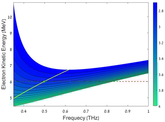
Figure 1.
Contour plot of the electron beam kinetic energies with respect to the resonant frequencies. The color bar represents the waveguide height (b) for the fundamental mode . The yellow line is the valid zero-slippage frequencies for the different electron beam kinetic energies. The red dashed line represents the energy of the ORGAD beam (6 ) and is used to mark the zero-slippage frequency (green pentagon).
By using Equations (5), and (6), we can define the electron beam energies with respect to the resonant frequencies and waveguide dimensions for the ultra-relativistic limit ():
The electron beam kinetic energy is calculated using the resonant Lorentz factor from Equation (14):
3. Tapering-Enhanced Superradiance
Spontaneous undulator radiation [47,48,49,50] by a beam of randomly injected electrons is incoherent. Thus, the total emitted radiation energy is proportional to the number of electrons , while the field average vanishes due to random interference of the generated wave packets [51,52]. To obtain superradiance [53,54], it is required that the electron bunch duration will be shorter than the radiation period . In this case, the generated wave packets from the bunched electrons are emitted and propagated in phase. Therefore, the resultant electric field of the emitted radiation is proportional to the number of electrons , and consequently, the total radiated energy is proportional to [5].
In a uniform undulator, the following equations are used in order to calculate the superradiance spectrum and energy [5,18]:
where is the bunching factor in the frequency domain, is the beam charge, is the wave impedance in the waveguide, is the undulator number of periods, is the undulator’s length, is the average undulator factor for the case of a planar undulator, and is the effective area of the waveguide radiation mode.
Due to the energy transfer from the electron beam to the radiation field (and, therefore, slowing down of the electron beam), it is not possible to maintain the synchronicity condition in the nonlinear regime. In order to compensate for this nonlinear detuning effect, the technique of undulator tapering has been used in the field of FEL [55]. This technique has also been used in the scheme of tapering-enhanced superradiance (TES) [56], which we analyze in the present paper, in which the electron bunch is trapped in a tapered undulator section by the superradiant radiation generated by it in a prior uniform section [18]. The undulator parameter can be tuned by varying the undulator period -period tapering or by varying the magnetic field -amplitude tapering. Amplitude tapering changes the undulator magnetic field amplitude, which leads to a change only in the undulator parameter . In the period tapering scheme, the period wavenumber changes and the undulator parameter also changes, which complicates the analysis and implementation of this scheme. Practically, it is also more challenging to fabricate an accurate tapered period undulator. Therefore, we chose to focus here on the amplitude tapering scheme.
To find the ratio between the tapering rate and the energy exchange rate while keeping the zero-slippage condition, we use Equation (6)
and differentiate both sides in terms of z, keeping constant
remains constant, since for the frequency of the radiation generated in the uniform part of the undulator, we constrain the detuning parameter to also remain constant along the tapered undulator section for the beam–radiation interaction [18]. Therefore, the reduction in the magnetic field amplitude compensates for the electron beam energy reduction. From (12), for ultra-relativistic limit (), the resonance average Lorentz factor along the entire interaction length is
where is the electromagnetic radiation wavenumber. From Equations (1), (19), and (20), the linear amplitude tapering rate defines the phase of a resonant electron:
where
is the normalized momentum of the electric field that interacts with the electron beam in the tapering section. In order for the electron to stay trapped, the tapering rate is limited by the condition .
4. Hamiltonian of a Waveguided Planar Undulator
In this section, we consider the case of amplitude tapering. In addition, we derive the Hamiltonian of an FEL interaction in a waveguided undulator to analyze how the electrons are “trapped” in phase-space along the interaction length in the nonlinear tapered undulator regime. Our model consists of an electron beam that exchanges its energy with the radiation field generated along the undulator. Using Equation (1), the Hamiltonian momentum coordinate is represented in terms of :
Since the resonance energy decreases due to the trapping dynamics of the electron beam along the tapered undulator, we should use a term that describes the variation in resonance energy. Therefore, the use of the parameter assists with describing the energy exchange, which corresponds to the change in resonance energy [18]:
The energy exchange along the undulator is
The phase synchronicity is obtained from the detuning parameter. Also, the detuning parameter is the derivative of the pondermotive phase (Equation (4)). Thus, the second equation used to construct the Hamiltonian is
Substituting using Equation (24) and substituting in terms of using Equations (18) and (20), we obtain
Equations (25) and (27) are used to construct the Hamiltonian (see Appendix A). The dynamics analysis is considered to be near resonance, . Also, we dropped the terms independent of the phase space variables to write
The resulting Hamiltonian has the form of a nonlinear pendulum; therefore, we define the local minima at and local maxima at . In addition, we can obtain the separatrix, which separates the bound and unbound solutions of a nonlinear system [55,57]. Since the Hamiltonian is constant on the separatrix, the energy exchange in terms of the pondermotive phase on the separatrix is
The phase-space is drawn using Equations (28) and (29) (see Figure 2).
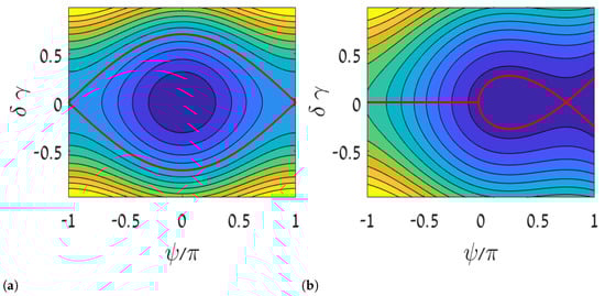
The Hamiltonian complies with the formulation of the dynamics of a bunched electron beam interacting with a radiation field in uniform and tapered undulators, as in [18]. The Hamiltonian from Equation (31) is consistent with Kroll’s expression [55], by performing some adjustments for his case of a helical undulator in free space with the substitutions , replacing K, and .
5. Simulations
The simulations are executed using GPT by applying custom elements representing the undulator design, a rectangular waveguide, and an amplitude-tapered undulator [58,59] (the scheme is shown in Figure 3). GPT outputs the particles’ transport parameters and radiation characteristics computed by numerical computation using a Runge–Kutta algorithm [60,61,62,63]. The elements that simulate the undulator use the following equations to describe the uniform and tapered undulator magnetic field components:
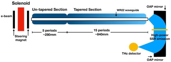
Figure 3.
Scheme of TES with 5 periods of uniform section + 15 periods of linear-tapering section, including a WR22 waveguide. The color gradient in the tapered section represents the variation of the undulator parameter K along this section.
The magnetic tapering rate is related to the undulator parameter tapering rate and to the resonant electron phase through Equation (21):
The nominal tapering rate parameter in Table 1 was evaluated for a particular , and the value was evaluated from the simulation results of the radiation field emitted by the prior uniform undulator section. GPT provides the electric field profile in each step during simulations. Thus, we can use its amplitude in each propagation step to evaluate and draw the separatrix. In the tapered section, the optimal resonance phase may be different from and depends on the radiation field generated in the uniform section. The parameter is used to modify the choice of the tapering rate and it is changed iteratively in order to find the maximal radiation energy emission. In the uniform section, , in Table 1 is determined to satisfy the synchronicity condition (Equation (5)) for the designed value of zero-slippage frequency THz. is nominally equal to unity, but it is left as an adjustable parameter for optimization of the output radiation.
Figure 4 shows the trajectory of a single electron in phase space in the uniform undulator. The electron is transported via a 20-period uniform undulator with the undulator parameters in Table 1. In this simulation, we verified that the electron performs synchrotron oscillations.
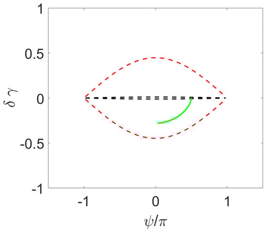
Figure 4.
Simulation of electron trajectory in a uniform undulator. Green dots correspond to the electron trajectory, black dashed lines correspond to the initial separatrix, and red dashed lines correspond to the final separatrix.
To demonstrate the consistency of the numerical computation with the analytical expression of superradiance in a uniform undulator (Equation (16)), we computed the radiated energy as a function of bunch charge and confirmed its quadratic scaling. Figure 5 exhibits the radiated energy as a function of beam charge () for an ideal electron beam (no space charge and ), which was varied from 5 up to 400 with 5 steps.
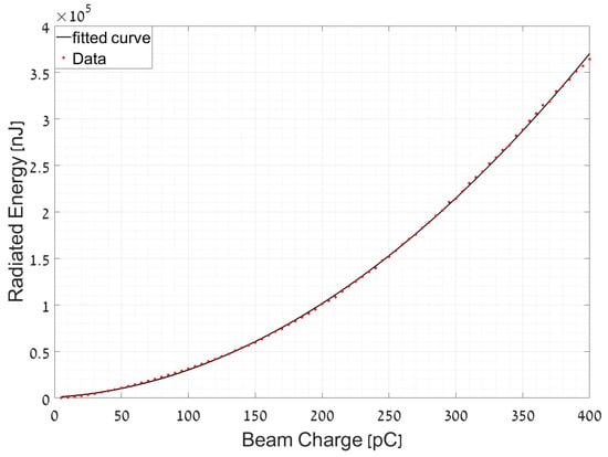
Figure 5.
Radiated energy as a function of ideal electron beam charge. The red dots represent simulation results and the black line is a parabolic fit.
Next, we simulate an ideal electron beam transported through a combined undulator structure consisting of uniform and linearly tapered sections (see Figure 3), where the number of tapered undulator periods is larger than the uniform one. The simulation contains a single undulator structure consisting of five uniform periods and fifteen linear-tapering periods. Figure 6 presents the initial and final positions of a single electron along the undulator in phase space.
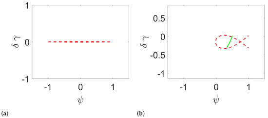
Figure 6.
Simulation of a linearly tapered undulator. (a) Start of the simulation and (b) end of the simulation. Green dots represent the electron trajectory and a single black dot is the final position.
We repeated this procedure for an electron beam with the ORGAD beam parameters. The optimal results for the ideal beam simulations were obtained for and , and for the ORGAD beam and . It is reasonable that is high for the non-ideal beam due to the reduction in the bunching factor and space-charge effects [64,65]. Figure 7 shows the ideal and ORGAD electron beam trajectories in phase space, and Table 2 presents the radiated energy values obtained from the simulations. Figure 8 shows the superradiance and tapering-enhanced superradiance energy growth along the entire interaction length for an ideal and for the ORGAD electron beams.
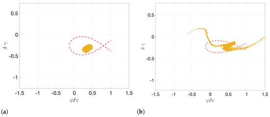
Figure 7.
Simulation of 10k macro particles transported via a combined structure consisting of a uniform and a linearly tapered undulator for (a) an ideal electron beam and (b) the ORGAD electron beam. The red dashed line corresponds to the separatrix and the yellow dots correspond to the macro particles.
Table 2.
Comparison of the maximal energy simulation results for a uniform undulator and a tapered undulator (TES) for an ideal and for the ORGAD electron beam for the number of periods ().
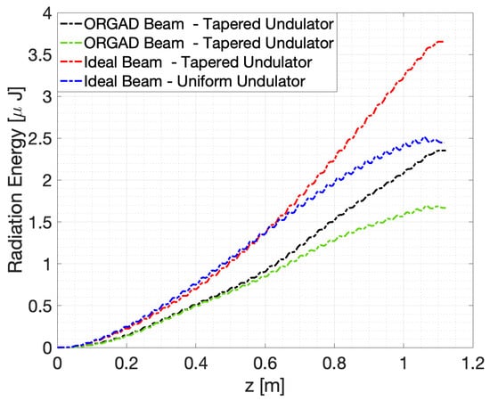
Figure 8.
Comparison of uniform and tapered undulator radiated energy along the interaction length for an ideal and a non-ideal electron beam.
Table 2 and Figure 8 show that TES produces more energy than superradiance emitted from a uniform undulator for both ideal and non-ideal electron beams. In other words, it confirms that tapered undulators prolong the interaction of the electron beam with the emitted radiation field, owing to the TES scheme. It should be stressed that much more radiative energy can be extracted with a longer tapered section. The enhancement factor of indicated in Table 2 corresponds to the optimization design of a TES experiment limited by undulator length (20 periods).
6. Conclusions
TES is an extension of superradiance in FEL that is facilitated by amplitude or period tapering. The use of a waveguide enables operation in zero-slippage. The zero-slippage condition allows extension of the interaction time of the electron beam with the generated radiation. A derived analysis of a waveguided planar undulator FEL model and numerical simulations are consistent and complement previous results.
The simulations were carried out both for an ideal electron beam and a realizable electron beam (ORGAD accelerator) transmitted through a uniform planar linearly planar undulator (as a reference). Further simulations of a beam transport through a combined undulator structure consisting of a uniform undulator followed by a linearly tapered undulator confirm the enhanced radiation emission of the TES scheme. In addition to the radiated power value, we verified that the electron beam is trapped in phase space. The obtained results are in good agreement with the proposed model, providing increased-efficiency emission using a tapered undulator operating in zero-slippage. In the present work, we obtained 40–50% enhancement in radiation power with the TES scheme compared to superradiant emission in a uniform undulator. This enhancement factor corresponds to design optimization under the limitation of undulator length (20 periods). Much larger radiation extraction can be attained with this scheme with a longer tapered undulator section.
Author Contributions
Conceptualization, A.G. and A.N.; Methodology, L.F., A.G. and A.N.; Software, L.F., A.W. and D.A.; Validation, A.G.; Formal analysis, L.F.; Investigation, L.F., A.G., A.F. and A.W.; Resources, A.G. and A.F.; Data curation, L.F.; Writing—original draft, L.F.; Writing—review & editing, A.G. and A.N.; Visualization, L.F.; Supervision, A.N.; Project administration, A.N.; Funding acquisition, A.N. All authors have read and agreed to the published version of the manuscript.
Funding
This work was supported by the Israel Science Foundation Grant No. 1705/22.
Data Availability Statement
Data is contained within the article.
Conflicts of Interest
The authors declare no conflict of interest.
Appendix A. Hamiltonian of a Waveguided Undulator Derivation
The Hamiltonian is a function that represents the total energy of a physical system using canonical coordinates. In order to construct the Hamiltonian, we use Hamilton’s equations:
Our model consists of an electron beam that exchanges its energy with the radiation field generated along the undulator. Using Equation (1), the Hamiltonian momentum coordinate is represented in terms of :
Since the resonance energy decreases due to the trapping dynamics of the electron beam along the tapered undulator, we should use a term that describes the variation in resonance energy. Therefore, the use of the parameter assists with describing the energy exchange, which corresponds to the change in resonance energy:
The energy exchange along the undulator is
The phase synchronicity is obtained from the detuning parameter. Also, the detuning parameter is the derivative of the pondermotive phase (Equation (4)). Thus, the second equation used to construct the Hamiltonian is
After substituting using Equation (A3) and substituting in terms of using Equations (18) and (20), we obtain:
Using Equations (A1a), (A1b), (A4), and (A6), we obtain the Hamiltonian:
Extracting out of the parentheses:
The dynamics analysis is considered to be near resonance, . Also, we dropped the terms independent of the phase space variables to write
The obtained Hamiltonian has the form of a nonlinear pendulum. Similar to the nonlinear pendulum, we define the local minima at and local maxima at . In addition, we can obtain the separatrix that separates between a nonlinear system’s bound and unbound solutions. Since the Hamiltonian is constant on the separatrix, we solve for the energy exchange term using the Hamiltonian at the edges.
By solving Equations (A9) and (A10) at the separatrix, we obtain the energy exchange in terms of the pondermotive phase:
References
- Nause, A.; Friedman, A.; Fukasawa, A.; Rosenzweig, J.; Roussel, R.; Spataro, B. First Operation of a Hybrid e-Gun at the Schlesinger Center for Compact Accelerators in Ariel University. In Proceedings of the 10th International Particle Accelerator Conference, Melbourne, Australia, 19–24 May 2019. [Google Scholar] [CrossRef]
- Feigin, L.; Weinberg, A.; Nause, A. Algorithm Verification of Single-Shot Relativistic Emittance Proposed Measuring Method. Electronics 2022, 11, 2092. [Google Scholar] [CrossRef]
- Feigin, L.; Nause, A. Single-shot emittance measurement and optimization of a hybrid photo-cathode gun beam. Nucl. Instrum. Methods Phys. Res. Sect. A Accel. Spectrometers Detect. Assoc. Equip. 2023, 1055, 168539. [Google Scholar] [CrossRef]
- Nause, A.; Friedman, A.; Weinberg, A.; Borodin, D.; Feigin, L.; Fukasawa, A.; Rosenzweig, J.; Roussel, R.; Spataro, B. 6 MeV novel hybrid (standing wave-traveling wave) photo-cathode electron gun for a THz superradiant FEL. Nucl. Instruments Methods Phys. Res. Sect. A Accel. Spectrom. Detect. Assoc. Equip. 2021, 1010, 165547. [Google Scholar] [CrossRef]
- Gover, A. Superradiant and stimulated-superradiant emission in prebunched electron-beam radiators. I. Formulation. Phys. Rev. ST Accel. Beams 2005, 8, 030701. [Google Scholar] [CrossRef]
- Kitaeva, G. Terahertz generation by means of optical lasers. Laser Phys. Lett. 2008, 5, 559–576. [Google Scholar] [CrossRef]
- Piyathilaka, H.P.; Sooriyagoda, R.; Dewasurendra, V.; Johnson, M.B.; Zawilski, K.T.; Schunemann, P.G.; Bristow, A.D. Terahertz generation by optical rectification in chalcopyrite crystals ZnGeP2, CdGeP2 and CdSiP2. Opt. Express 2019, 27, 16958–16965. [Google Scholar] [CrossRef]
- Kroh, T.; Matlis, N.; Kärtner, F. High-energy Single-cycle Terahertz Sources for Compact Particle Accelerators and Manipulators. In Proceedings of the 14th International Particle Accelerator Conference, Venice, Italy, 7–12 May 2023. [Google Scholar] [CrossRef]
- Pacey, T.H.; Saveliev, Y.; Healy, A.; Huggard, P.G.; Alderman, B.; Karataev, P.; Fedorov, K.; Xia, G. Continuously tunable narrow-band terahertz generation with a dielectric lined waveguide driven by short electron bunches. Phys. Rev. Accel. Beams 2019, 22, 091302. [Google Scholar] [CrossRef]
- Ciocci, F.; Doria, A.; Gallerano, G.P.; Giabbai, I.; Kimmitt, M.F.; Messina, G.; Renieri, A.; Walsh, J.E. Observation of coherent millimeter and submillimeter emission from a microtron-driven Cherenkov free-electron laser. Phys. Rev. Lett. 1991, 66, 699–702. [Google Scholar] [CrossRef]
- Sideris, S.; Ellenbogen, T. Terahertz generation in parallel plate waveguides activated by nonlinear metasurfaces. Opt. Lett. 2019, 44, 3590. [Google Scholar] [CrossRef]
- Vicario, C.; Ovchinnikov, A.V.; Ashitkov, S.I.; Agranat, M.B.; Fortov, V.E.; Hauri, C.P. Generation of 0.9-mJ THz pulses in DSTMS pumped by a Cr:Mg2SiO4 laser. Opt. Lett. 2014, 39, 6632–6635. [Google Scholar] [CrossRef]
- Liao, G.; Li, Y.; Liu, H.; Scott, G.G.; Neely, D.; Zhang, Y.; Zhu, B.; Zhang, Z.; Armstrong, C.; Zemaityte, E.; et al. Multimillijoule coherent terahertz bursts from picosecond laser-irradiated metal foils. Proc. Natl. Acad. Sci. USA 2019, 116, 3994–3999. [Google Scholar] [CrossRef]
- Balal, N.; Magori, E.; Yahalom, A. Design of a Permanent Magnet Wiggler for a THz Free Electron Laser. Acta Phys. Pol. A 2015, 128, 259–264. [Google Scholar] [CrossRef]
- Dicke, R.H. Coherence in Spontaneous Radiation Processes. Phys. Rev. 1954, 93, 99–110. [Google Scholar] [CrossRef]
- Gross, M.; Haroche, S. Superradiance: An essay on the theory of collective spontaneous emission. Phys. Rep. 1982, 93, 301–396. [Google Scholar] [CrossRef]
- Fisher, A.; Park, Y.; Lenz, M.; Ody, A.; Agustsson, R.; Hodgetts, T.; Murokh, A.; Musumeci, P. Single-pass high-efficiency terahertz free-electron laser. Nat. Photonics 2022, 16, 1–7. [Google Scholar] [CrossRef]
- Gover, A.; Ianconescu, R.; Friedman, A.; Emma, C.; Sudar, N.; Musumeci, P.; Pellegrini, C. Superradiant and stimulated-superradiant emission of bunched electron beams. Rev. Mod. Phys. 2019, 91, 035003. [Google Scholar] [CrossRef]
- Duris, J.; Murokh, A.; Musumeci, P. Tapering Enhanced Stimulated Superradiant Amplification. New J. Phys. 2015, 17, 063036. [Google Scholar] [CrossRef]
- Sudar, N.; Musumeci, P.; Duris, J.; Gadjev, I.; Polyanskiy, M.; Pogorelsky, I.; Fedurin, M.; Swinson, C.; Kusche, K.; Babzien, M.; et al. High Efficiency Energy Extraction from a Relativistic Electron Beam in a Strongly Tapered Undulator. Phys. Rev. Lett. 2016, 117, 174801. [Google Scholar] [CrossRef]
- Zhao, Z.; Xu, Y.; Jia, Q.; Li, H. High efficiency tapered free-electron lasers with a prebunched electron beam from echo-enabled harmonic generation. Phys. Rev. Accel. Beams 2023, 26, 070701. [Google Scholar] [CrossRef]
- Emma, C.; Sudar, N.; Musumeci, P.; Urbanowicz, A.; Pellegrini, C. High efficiency tapered free-electron lasers with a prebunched electron beam. Phys. Rev. Accel. Beams 2017, 20, 110701. [Google Scholar] [CrossRef]
- Slater, J. Tapered-wiggler free-electron laser optimization. IEEE J. Quantum Electron. 1981, 17, 1476–1479. [Google Scholar] [CrossRef]
- Snively, E. Electron-THz Wave Interactions in a Guided Inverse Free Electron Laser; University of California: Los Angeles, CA, USA, 2018. [Google Scholar]
- Schmüser, P.; Dohlus, M.; Rossbach, J.; Behrens, C. Free-Electron Lasers in the Ultraviolet and X-ray Regime; Springer International Publishing: Berlin/Heidelberg, Germany, 2014. [Google Scholar] [CrossRef]
- Clarke, J. The Science and Technology of Undulators and Wigglers; Oxford University Press: Oxford, UK, 2004. [Google Scholar] [CrossRef]
- Jeong, Y.U.; Kawamura, Y.; Toyoda, K.; Nam, C.H.; Lee, S.S. Observation of coherent effect in undulator radiation. Phys. Rev. Lett. 1992, 68, 1140–1143. [Google Scholar] [CrossRef]
- Krinsky, S. Undulators as Sources of Synchrotron Radiation. IEEE Trans. Nucl. Sci. 1983, 30, 3078–3082. [Google Scholar] [CrossRef][Green Version]
- Andersson, A.; Johnson, M.S.; Nelander, B. Coherent synchrotron radiation in the far-infrared from a 1 mm electron bunch. Opt. Eng. 2000, 39, 3099–3105. [Google Scholar] [CrossRef]
- Hirschmugl, C.J.; Sagurton, M.; Williams, G.P. Multiparticle coherence calculations for synchrotron-radiation emission. Phys. Rev. A 1991, 44, 1316–1320. [Google Scholar] [CrossRef]
- Green, G.K. Spectra and Optics of Synchrotron Radiation; Brookhaven National Lab. (BNL): Upton, NY, USA, 1976. [CrossRef]
- Asakawa, M.; Sakamoto, N.; Inoue, N.; Yamamoto, T.; Mima, K.; Nakai, S.; Chen, J.; Fujita, M.; Imasaki, K.; Yamanaka, C.; et al. A millimeter-range FEL experiment using coherent synchrotron radiation emitted from electron bunches. Nucl. Instrum. Methods Phys. Res. Sect. A: Accel. Spectrometers, Detect. Assoc. Equip. 1994, 341, 72–75. [Google Scholar] [CrossRef]
- Curry, E.; Fabbri, S.; Musumeci, P.; Gover, A. THz-driven zero-slippage IFEL scheme for phase space manipulation. New J. Phys. 2016, 18, 113045. [Google Scholar] [CrossRef]
- Gover, A.; Hartemann, F.V.; Le Sage, G.P.; Luhmann, N.C.; Zhang, R.S.; Pellegrini, C. Time and frequency domain analysis of superradiant coherent synchrotron radiation in a waveguide free-electron laser. Phys. Rev. Lett. 1994, 72, 1192–1195. [Google Scholar] [CrossRef]
- Gallerano, G.; Doria, A.; Giovenale, E.; Renieri, A. Compact free electron lasers: From Cerenkov to waveguide free electron lasers. Infrared Phys. Technol. 1999, 40, 161–174. [Google Scholar] [CrossRef]
- Marcuvitz, N. Waveguide Handbook; Institution of Electrical Engineers, McGraw-Hill: New York, NY, USA, 1986. [Google Scholar]
- Wiedemann, H. Particle accelerator physics; Springer Nature: Berlin/Heidelberg, Germany, 2015. [Google Scholar]
- Minty, M.; Zimmermann, F. Measurement and Control of Charged Particle Beams; Springer Nature: Berlin/Heidelberg, Germany, 2003. [Google Scholar] [CrossRef]
- Snively, E.C.; Xiong, J.; Musumeci, P.; Gover, A. Broadband THz amplification and superradiant spontaneous emission in a guided FEL. Opt. Express 2019, 27, 20221–20230. [Google Scholar] [CrossRef]
- Pozar, D. Microwave Engineering, 4th ed.; Wiley: Hoboken, NJ, USA, 2011. [Google Scholar]
- Xu, K. Silicon electro-optic micro-modulator fabricated in standard CMOS technology as components for all silicon monolithic integrated optoelectronic systems. J. Micromech. Microeng. 2021, 31, 054001. [Google Scholar] [CrossRef]
- Collin, R. Foundations for Microwave Engineering, 2nd ed.; McGraw-Hill Series in Electrical Engineering: Radar and Antennas; IEEE Press: New York, NY, USA, 2007. [Google Scholar]
- Rosenzweig, J.B. Fundamentals of Beam Physics; Oxford University Press: Oxford, UK, 2003. [Google Scholar]
- Jackson, J. Classical Electrodynamics; Wiley: Hoboken, NJ, USA, 2012. [Google Scholar]
- Jerby, E.; Gover, A. Investigation of the gain regimes and gain parameters of the free electron laser dispersion equation. IEEE J. Quantum Electron. 1985, 21, 1041–1058. [Google Scholar] [CrossRef][Green Version]
- Bartolini, R.; Doria, A.; Gallerano, G.; Renieri, A. Theoretical and experimental aspects of a waveguide FEL. Nucl. Instrum. Methods Phys. Res. Sect. A Accel. Spectrometers Detect. Assoc. Equip. 1991, 304, 417–420. [Google Scholar] [CrossRef]
- Bratman, V.; Lurie, Y.; Oparina, Y.; Savilov, A. Capabilities of Terahertz Cyclotron and Undulator Radiation from Short Ultrarelativistic Electron Bunches. Instruments 2019, 3, 55. [Google Scholar] [CrossRef]
- Neuman, C.P.; Graves, W.S.; O’Shea, P.G. Coherent off-axis undulator radiation from short electron bunches. Phys. Rev. ST Accel. Beams 2000, 3, 030701. [Google Scholar] [CrossRef]
- Doria, A.; Bartolini, R.; Feinstein, J.; Gallerano, G.; Pantell, R. Coherent emission and gain from a bunched electron beam. IEEE J. Quantum Electron. 1993, 29, 1428–1436. [Google Scholar] [CrossRef]
- Bonifacio, R.; Pellegrini, C.; Narducci, L. Collective instabilities and high-gain regime in a free electron laser. Opt. Commun. 1984, 50, 373–378. [Google Scholar] [CrossRef]
- Ratner, D.; Hemsing, E.; Gover, A.; Marinelli, A.; Nause, A. Subradiant spontaneous undulator emission through collective suppression of shot noise. Phys. Rev. Spec. Top.-Accel. Beams 2015, 18, 050703. [Google Scholar] [CrossRef]
- Gover, A.; Dyunin, E.; Duchovni, T.; Nause, A. Collective microdynamics and noise suppression in dispersive electron beam transport. Phys. Plasmas 2011, 18, 123102. [Google Scholar] [CrossRef]
- Pinhasi, Y.; Lurie, Y. Generalized theory and simulation of spontaneous and super-radiant emissions in electron devices and free-electron lasers. Phys. Rev. E 2002, 65, 026501. [Google Scholar] [CrossRef]
- Lurie, Y.; Pinhasi, Y. Enhanced super-radiance from energy-modulated short electron bunch free-electron lasers. Phys. Rev. ST Accel. Beams 2007, 10, 080703. [Google Scholar] [CrossRef]
- Kroll, N.; Morton, P.; Rosenbluth, M. Free-electron lasers with variable parameter wigglers. IEEE J. Quantum Electron. 1981, 17, 1436–1468. [Google Scholar] [CrossRef]
- Musumeci, P.; Tochitsky, S.Y.; Boucher, S.; Clayton, C.E.; Doyuran, A.; England, R.J.; Joshi, C.; Pellegrini, C.; Ralph, J.E.; Rosenzweig, J.B.; et al. High Energy Gain of Trapped Electrons in a Tapered, Diffraction-Dominated Inverse-Free-Electron Laser. Phys. Rev. Lett. 2005, 94, 154801. [Google Scholar] [CrossRef]
- Park, Y. Tapering Enhanced Stimulated Superradiant Amplification; University of California: Los Angeles, CA, USA, 2022. [Google Scholar]
- Fisher, A.; Musumeci, P.; Van der Geer, S.B. Self-consistent numerical approach to track particles in free electron laser interaction with electromagnetic field modes. Phys. Rev. Accel. Beams 2020, 23, 110702. [Google Scholar] [CrossRef]
- Musumeci, P.; Fisher, A.; Gover, A.; Nanni, E.; Snively, E.; van der Geer, B. A Waveguide-Based High Efficiency Super-Radiant FEL Operating in the THz Regime. In Proceedings of the 39th International Free Electron Laser Conference, Hamburg, Germany, 26–30 August 2019; p. TUP036. [Google Scholar] [CrossRef]
- van der Geer, S.; Setija, I.; Smorenburg, P.; Williams, P.; de Loos, M. GPT-CSR: A New Simulation Code for CSR Effects. In Proceedings of the 60th ICFA Advanced Beam Dynamics Workshop (FLS’18), Shanghai, China, 5–9 March 2018; Springer: Geneva, Switzerland, 2018. Number 60 in ICFA Advanced Beam Dynamics Workshop. pp. 157–159. [Google Scholar] [CrossRef]
- Geer, S.; de Loos, M.; Bongerd, D.; Soest, X. General Particle Tracer: A New 3D Code for Accelerator and Beamline Design. In Proceedings of the 5th European Particle Accelerator Conference, Sitges, Spain, 10–14 June 1996. [Google Scholar]
- van der Geer, B.; De Loos, M. Applications of the General Particle Tracer code. In Proceedings of the 1997 Particle Accelerator Conference (Cat. No.97CH36167), Vancouver, BC, Canada, 16 May 1997; Volume 2, pp. 2577–2579. [Google Scholar] [CrossRef]
- van der Geer, B.; De Loos, M. The general particle tracer code:design, implementation and application. J. Bus. Commun. 2001. [Google Scholar] [CrossRef]
- Kim, K.J. Rf and space-charge effects in laser-driven rf electron guns. Nucl. Instrum. Methods Phys. Res. Sect. A Accel. Spectrometers Detect. Assoc. Equip. 1989, 275, 201–218. [Google Scholar] [CrossRef]
- Rosenzweig, J.; Colby, E. Charge and wavelength scaling of RF photoinjectors: A design tool. In Proceedings of the Particle Accelerator Conference, Dallas, TX, USA, 1–5 May 1995; Volume 2, pp. 957–960. [Google Scholar] [CrossRef]


Disclaimer/Publisher’s Note: The statements, opinions and data contained in all publications are solely those of the individual author(s) and contributor(s) and not of MDPI and/or the editor(s). MDPI and/or the editor(s) disclaim responsibility for any injury to people or property resulting from any ideas, methods, instructions or products referred to in the content. |
© 2024 by the authors. Licensee MDPI, Basel, Switzerland. This article is an open access article distributed under the terms and conditions of the Creative Commons Attribution (CC BY) license (https://creativecommons.org/licenses/by/4.0/).