Article

Reconfigurable Holographic Surface-Assisted Wireless Secrecy Communication System

College of Computer and Information Engineering, Nanjing Tech University, Nanjing 211816, China
*
Author to whom correspondence should be addressed.
Electronics 2024, 13(7), 1359; https://doi.org/10.3390/electronics13071359
Submission received: 11 March 2024 / Revised: 1 April 2024 / Accepted: 1 April 2024 / Published: 4 April 2024
(This article belongs to the Section Microwave and Wireless Communications)

Abstract

:
This new antenna, called the reconfigurable holographic surface (RHS), is lightweight and compact, and it can precisely steer many beams at once. Because of its reflecting characteristic, it differs from the reconfigurable intelligent surface (RIS), which is frequently employed as a passive relay. To leverage the holographic technology and generate the necessary beam, RHS is most likely to be integrated with the transceiver as an ultra-thin and lightweight planer antenna. This has enormous potential to satisfy the growing demands of the future generation network. This paper is the first to study a wireless secrecy communication system with a base station that has and is helped by an RHS. We suggest a strategy for simultaneously optimizing the holographic beamforming at the RHS and the digital beamforming at the base station with the introduction of artificial noise (AN) to attain the highest secrecy rate. However, because of its non-convexity and changeable coupling, this problem is challenging to solve. A proficient algorithm that utilizes alternating optimization and is capable of solving the problem below the ideal level is suggested. According to simulation studies, RHS outperforms RIS in terms of enhancing the performance of wireless secrecy communication systems, indicating that RHS has a wide range of potential applications in the realm of physical layer security.

1. Introduction

Demanding specifications for capacity enhancement and low power consumption in antenna hardware components have been placed on sixth generation (6G) wireless communication [1]. Traditional phase-shifting circuits have been widely used to improve wireless communication systems’ performance, but they need a large investment in phase shifters and reflecting materials. Conventional phase-shifting arrays cannot keep up with the exponential growth in communication demands [2].
Currently, to create an intelligent and reconfigurable communication system, intelligent reflective surfaces (RISs) are frequently employed in the field of wireless communication [3,4,5,6,7]. A vast array of passive reflective metamaterials make up RISs. To enhance system efficiency, they are frequently utilized as relays in wireless communication systems because of their reflecting qualities and reconfigurable benefits. Furthermore, RISs have been thoroughly studied in the area of physical layer security [8,9,10], where they can be used to optimize both RIS reflection beamforming and base station (BS) transmit beamforming in tandem to increase the secrecy rate.
In addition to RIS, the current holographic antenna is a planar antenna that is incredibly thin, consumes very little power, and is capable of multi-beam steering. By creating a holographic pattern on the surface by the interference principle, the holographic antenna records the interference between the reference wave and the desired object wave [11]. The goal of beamforming is accomplished when the holographic pattern creates the required radiation pattern when the reference wave propagates on the surface. The radiation pattern is fixed when the holographic pattern is formed, which is a flaw in the standard holographic antenna. Thankfully, this flaw has been overcome by the reconfigurable holographic surface (RHS) composed of controlled metamaterials [12].
The RHS is a compact and energy-efficient planar antenna composed of metamaterial radiation elements. The RHS can perform dynamic beamforming because the magnetic or electric bias field can intelligently modulate the electromagnetic response of the metamaterial radiation elements. Unlike traditional phased arrays, RHS produces the required radiation pattern by adjusting the reference wave’s radiation amplitude, doing away with the requirement for intricate phase-shifting linkages [13].
The RHS and the RIS, employing traditional phased arrays technology, exhibit significant differences in both structure and operation. The RHS seamlessly integrates its RF front end into a PCB, facilitating transceiver implementation, while the RIS, employing traditional phased-array technology, relies on an external front end, necessitating a control link for phase-shift reconstruction. In terms of functionality, the RHS acts as a leaky-wave antenna, sequentially exciting radiation elements, whereas the RIS functions as a reflection antenna, simultaneously exciting all elements. Notably, the RHS excels as a transmit–receive antenna for mobile platforms, while the RIS finds common usage as a passive relay to extend cell coverage [14].
RHS has garnered attention because of its exceptional qualities. In the literature, people mainly investigate the hardware production [15,16] and radiation pattern control of the RHS [13,17]. In [16], the radiation elements of the holographic surface are fabricated with a complementary electric-LC (cELC) resonator connected to a p-i-n diode. When the diode is in the off state, it will excite the reference wave into the object wave propagating in free space, and when the diode is on, it will be difficult to excite energy into the free space. In [17], the author established a multi-user communication system assisted by the RHS. By using holographic technology, holographic beamforming was performed by the RHS, and a hybrid beamforming scheme was proposed to improve the communication rate.
People have studied the system performance of the RHS because of its precise beam steering capability and used it in multiple-access, multi-user communication; low-Earth-orbit (LEO) satellite communication; and other applications [18,19,20]. Recently, in [21], the author developed a point-to-point real-time data transmission platform to confirm the system’s functionality and deployed the holographic surface in the radio field to actualize the holographic radio. It is evident from the experimental results that the holographic surface has a lot of potential for holographic radio. Previous scholarly research indicates that the holographic surface performs exceptionally well in enhancing communication system performance; nevertheless, research on secrecy communication has not yet been taken into consideration from the standpoint of physical layer security.
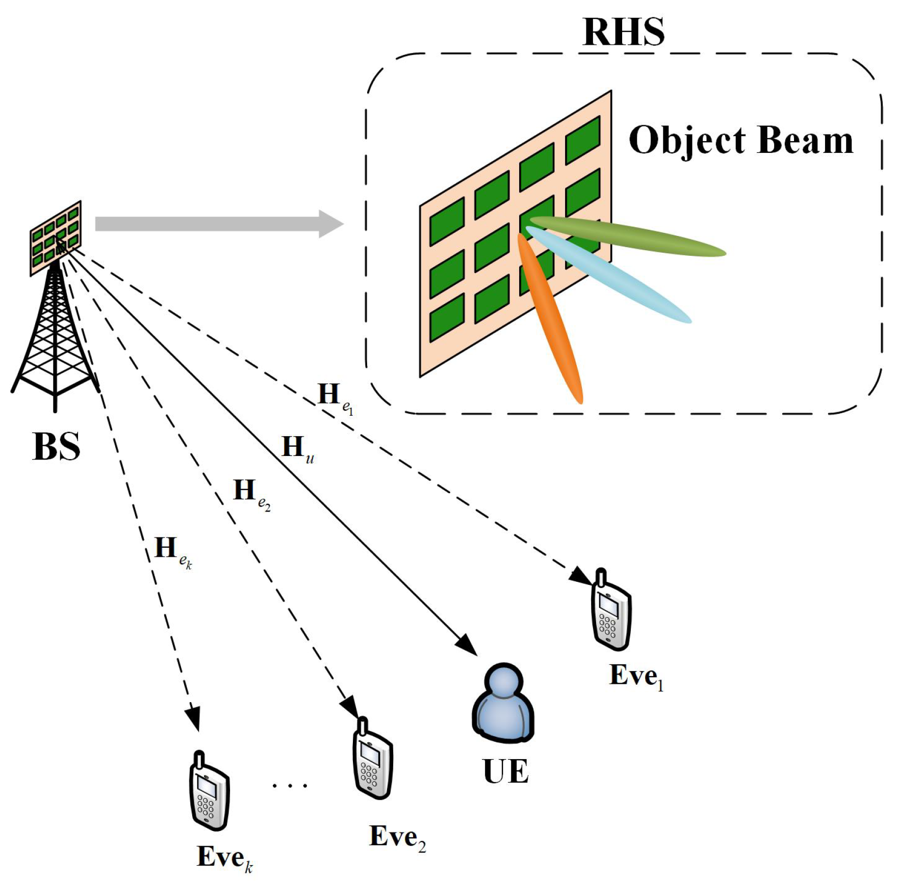
In addition to proposing artificial noise (AN), an efficient method for raising the secrecy rate in traditional wireless communication systems, this work is the first to examine a secrecy communication system aided by the RHS. We added an RHS to the base station (BS), as depicted in Figure 1, to help boost the secrecy rate of legal receivers with many eavesdroppers. To address this problem, we introduce a unique hybrid beamforming method that simultaneously maximizes the secrecy rate by optimizing the holographic beamforming of the RHS and the digital beamforming of the BS. This problem is a complex-domain optimization problem subject to the real-domain amplitude constraints, which makes it different from the standard RIS-aided secrecy communication system [22]. As a result, the conventional approach does not perform well in solving this problem. New approaches are required to address this issue.
To solve the physical layer security problem of maximizing the secrecy rate, our contributions in this paper can be summarized as follows:
  • We propose a secrecy communication system assisted by RHS. Specifically, we integrate the RHS into the base station (BS) to enhance the system’s beamforming accuracy and introduce artificial noise, a commonly used technique in the domain of physical layer security, to improve the overall secrecy rate. The system is designed to operate in the presence of multiple eavesdroppers and a legitimate user. To address this challenge, we propose a hybrid beamforming scheme that jointly optimizes the digital beamforming at the BS and the holographic beamforming at the RHS.
  • We formulate a secrecy rate maximization problem subject to the transmit power of the base station and the normalized radiation amplitude of the holographic surface. This problem is difficult to solve because it is an optimization problem in which the objective function is non-convex and the optimization variables are coupled. However, it is relatively easy to optimize one optimization variable while the other optimization variable is fixed, so we propose an algorithm of an alternate solution. We decompose the problem into two subproblems: the digital beamforming at the base station and the holographic beamforming at the holographic surface. By alternately solving the two subproblems, convergence will be achieved in the end to maximize the secrecy rate.
  • Based on simulation results, it is demonstrated that the holographic surface presents promising potential for applications in the field of physical layer security. The simulations have verified the impact of transmission power, eavesdropper quantity, and antenna size on its performance. Additionally, a comparison with an equivalent-sized RIS has been conducted. The simulation results reveal that the holographic surface outperforms the RIS in terms of secrecy of the communication system.
The remainder of this paper is organized as follows. The holographic rules and the hardware construction of the holographic surface are presented in Section 2. We present our scenario and system model for our secrecy communication system in Section 3. In Section 4, we pose the problem of optimizing the secrecy rate and provide a detailed description of the algorithm used to solve it. To verify the algorithm’s viability and the holographic surface’s functionality in the secrecy communication system, we simulate the system model in Section 5. Ultimately, our conclusions are presented in Section 6.
Notations: j = 1 is the imaginary unit, and · denotes the conjugate. · represents the modulus of a complex number, while R e . represents the real part of a complex number. CN μ , σ 2 denotes the distribution of a circularly symmetric complex Gaussian random variable with mean μ and variance σ 2 . T r M denotes the trace of the square matrix M, while M 0 denotes it to be positive semi-definite. r a n k ( V ) denotes the rank of any general matrix V , and d i a g ( V ) represents the diagonalization. C Y × X denotes the space of Y × X complex-valued matrices.

2. Reconfigurable Holographic Surface

2.1. Physical Structure

Holographic surface is a type of leaky-wave antenna, which mainly consists of four parts, including feeds, waveguides, metamaterial radiation elements, and radiation amplitude controllers. The feeds are embedded in the bottom layer of the RHS to generate reference waves carrying useful information propagating along the RHS. Such a structure makes the RHS thinner than traditional antenna arrays. The waveguide serves as the transmission medium for the reference wave and guides it to propagate on the surface. Metamaterial radiation elements are used to generate leaky waves. When it is excited by the reference wave, it will radiate an electromagnetic wave, which is called a leaky wave. Radiation amplitude controllers are implemented to regulate the amplitude characteristics of each component. By manipulating the magnetic or electric field bias, the radiation characteristics of each element can be adjusted, enabling the implementation of beamforming [14].

2.2. Holographic Principle

The RHS controls the leaky waves generated by each radiation element by constructing a holographic pattern (recording the interference between the reference wave and the target wave) and, by superimposing the leaky waves of each element, can obtain a beam in the desired direction.
As shown in Figure 2, we adopt Cartesian coordinates, where the x o y plane coincides with the RHS surface, and the z-axis is vertical to the RHS surface. We assume that the holographic surface has X × Y radiation elements and K feeds. In the x , y -th radiation elements, the phase of the reference wave excited by the k-th feed and the phase of the object wave radiated in the direction of θ 0 , φ 0 are respectively denoted as
Ψ r e f r x , y k = exp j k s · r x , y k ,
Ψ o b j r x , y , θ 0 , φ 0 = exp j k f θ 0 , φ 0 · r x , y ,
where r x , y is the position vector of the x , y -th radiation element, k f is the propagation vector of the leaky wave in the desired direction, r x , y k is the distance vector from the k-th feed to the x , y -th radiation element, and k s is the propagation vector of the reference wave.
According to the holographic interference rule, the interference between reference wave and object wave can be denoted as
Ψ i n t f r x , y k , θ 0 , φ 0 = Ψ obj r x , y , θ 0 , φ 0 Ψ r e f r x , y k .
When the holographic pattern is excited by the reference wave, the resulting beam will satisfy Ψ i n t f Ψ r e f Ψ o b j Ψ r e f 2 ; as such, a beam in the desired direction is formed.
Note that, when the phase difference increases, Re Ψ i n t f will decrease, which meets the requirements of amplitude control, so we construct the normalized amplitude with Re Ψ i n t f to represent the radiation amplitude of each radiation element. Therefore, the radiation amplitude of the x , y -th radiation element in the direction θ 0 , φ 0 can be expressed as
M r x , y k , θ 0 , φ 0 = Re Ψ i n t f r x , y k , θ 0 , φ 0 + 1 2 .
Setting the radiation amplitude of each reference wave according to (4) will get the object wave in the desired direction θ 0 , φ 0 . The proof is given in Appendix A.

3. System Model

In this section, we first introduce the RHS-assisted secrecy communication system and the hybrid beamforming scheme and then present the communication model.

3.1. Scenario Description

As shown in Figure 1, we consider a wireless communication system in which a legitimate base station (BS) intends to send confidential information to a legitimate receiver (UE), while there are K eavesdroppers (Eves) who are distributed in the system randomly. Different from traditional RIS-assisted secrecy communication systems, we consider equipping the RHS on the base station to achieve beamforming by using holographic rules so that useful signals can be effectively transmitted to the user, avoiding eavesdroppers.

3.2. Hybrid Beamforming Scheme

BS first needs to digitally pre-process the signal in the baseband to compensate for the disadvantage that the RHS does not have a digital processing ability. Without loss of generality, we assume that the base station encodes the user signal and the artificial noise via vectors v 1 , v 2 , respectively, and then up-converts the signal to the carrier frequency via the RF chain and sends it on to the feeds connected to the RF chain. The number of RF chains is the same as the number of feeds on the RHS. Each RF chain is connected to a feed, and the signal is transmitted to the feed where it is converted by high-frequency current into an electromagnetic wave (which is also called a reference wave) that is transmitted on the RHS. The amplitude of the object wave excited at each radiation element is controlled by an amplitude controller to obtain the beam propagating in the desired direction.

3.3. Communication Model

Denote the independent information and jamming signal as s CN 0 , 1 and a CN 0 , 1 , respectively, so that the signal transmitted from BS can be denoted as
x = v 1 s + v 2 a .
Assuming that BS has a maximum transmit power P m a x , then we have v 1 H v 1 + v 2 H v 2 P m a x . We assume that the UE and Eves are each equipped with J receive antennas and a single RF receive chain. The final signal received by UE and the Eves can be denoted as
y l = W l H H l M v 1 s + v 2 a + W l H z l , l u , e k ,
where W l is a J × 1 RF combiner at UE and each Eve, implemented by using phase shifting such that W l ( j ) 2 = 1 . In this research, we have simplified it to a uniform linear phased array for convenience, so W l = 1 , e j k f d s sin ϕ l , , e j k f J 1 d s sin ϕ l T , where ϕ l is the angle of signal arrival to the antenna array in reserve, and d s is the distance between the antennas of the receivers. The matrix M C X Y × K is composed of M x , y · e j k s · r x , y k , where e j k s · r x , y k is the phase of the reference wave, and z l CN 0 , σ 2 I J is the additive white Gaussian noise. The matrix H l C J × X Y is the complex equivalent channel between RHS and UE or Eves. The matrix M can be decomposed into d i a g ( m ) Θ , where m = M 1 , 1 , , M x , y , , M X , Y T , 0 M x , y 1 , and Θ is the matrix of the phase e j k s · r x , y k . By changing variables as W l H H l d i a g ( m ) Θ = m H H ^ l , where H ^ l = d i a g ( W l H H l ) Θ , the signal-to-interference plus noise ratio (SINR) at UE or Eves can be derived as
γ l = m H H ^ l v 1 2 J σ 2 + m H H ^ l v 2 2 , l u , e k .
In our research, the propagation environment between the BS and receivers is modeled as a sparse millimeter-wave channel with I paths. We assume that all channel state information (CSI) is known at the BS to characterize the optimal performance of the considered RHS-assisted secrecy communication system. Therefore, the achievable rate of UE or Eves can be denoted as
R l = log 2 1 + m H H ^ l v 1 2 J σ 2 + m H H ^ l v 2 2 , l u , e k .

4. Problem Formulation and Algorithm Design

4.1. Problem Formulation

We aim to maximize the achievable secrecy rate by optimizing digital beamformer v 1 , v 2 and holographic beamformer M x , y , subject to the maximum power constraint at BS. The problem can be formulated as
( P 0 ) : max v 1 , v 2 , m R u max k R e k s . t . v 1 H v 1 + v 2 H v 2 P max , 0 M x , y 1 .
Since both R u and R e k are non-concave functions as well as the coupled optimization variables, P 0 is difficult to solve, but we find that when one of v 1 , v 2 or m is fixed, it will be easy to solve, so we propose an optimization method based on an alternating algorithm. By alternately optimizing one of v 1 , v 2 or m while the other is fixed at each iteration, convergence is finally achieved through multiple iterations. Therefore, in order to effectively solve P 0 , we decompose it into two subproblems, i.e., digital beamforming to optimize v 1 , v 2 and holographic beamforming to optimize m . By iteratively solving these two subproblems, we can eventually solve P 0 sub-optimally. Different from the traditional phase-controlled beamforming design, P 0 is a complex-domain optimization problem subject to nontraditional real-domain constraints. The traditional algorithm is no longer applicable here. For the optimization problem of m , we use the traversal approach to approximate solving. In the next two subsections, we will solve these two subproblems.

4.2. Digital Beamforming Design

In this section, we optimize the digital beamforming vectors v 1 , v 2 given the holographic beamforming vector m . Let h ˜ u H = m H H ^ u and h ˜ e k H = m H H ^ e k , and then we denote H ˜ u = h ˜ u h ˜ u H and H ˜ e k = h ˜ e k h ˜ e k H . Therefore, P 0 can be transformed to
( P 1.1 ) : max v 1 , v 2 log 2 1 + v 1 H H ˜ u v 1 J σ 2 + v 2 H H ˜ u v 2 max k log 2 1 + v 1 H H ˜ e k v 1 J σ 2 + v 2 H H ˜ e k v 2 s . t . v 1 H v 1 + v 2 H v 2 P max .
Note that v 1 H H ˜ l v 1 = Tr H ˜ l v 1 v 1 H and v 2 H H ˜ l v 2 = Tr H ˜ l v 2 v 2 H , l u , e k . We define two matrices V 1 = v 1 v 1 H and V 2 = v 2 v 2 H , and then it follows that V 1 0 , V 2 0 and r a n k V 1 = r a n k V 2 = 1 . Since the rank-1 constraint is a non-convex constraint, we use the semidefinite relaxation (SDR) method to remove this constraint. Then, the ( P 1.1 ) can be transformed to
( P 1.2 ) : max V 1 , V 2 log 2 1 + Tr H ˜ u V 1 J σ 2 + Tr H ˜ u V 2 max k log 2 1 + Tr H ˜ e k V 1 J σ 2 + Tr H ˜ e k V 2 s . t . V 1 , V 2 V ,
where V = V 1 , V 2 | Tr V 1 + V 2 P m a x , V 1 0 , V 2 0 is the feasible set for V 1 , V 2 . This problem is still difficult to solve because the objective function is not jointly concave with respect to V 1 , V 2 . In order to overcome this problem, we propose the following Lemma 1 [23].
Lemma 1.
Consider the function φ t = t x + ln t + 1 , for any x > 0 , then we have
ln x = max t > 0 φ t ;
the optimal solution is t = 1 / x .
The upper bound for φ t can be given by Lemma 1. By setting x = Tr H ˜ u V 2 + J σ 2 and t = t u as well as applying Lemma 1, we have
R u ln 2 = ln Tr H ˜ u V 1 + V 2 + J σ 2 t u Tr H ˜ u V 2 + J σ 2 = max t u > 0 φ u V 1 , V 2 , t u ,
where φ u V 1 , V 2 , t u = ln Tr H ˜ u V 1 + V 2 + J σ 2 t u Tr H ˜ u V 2 + J σ 2 + ln t u + 1 . This function is jointly concave with respect to V 1 , V 2 .
In the same way, letting x = Tr H ˜ e k V 1 + V 2 + J σ 2 and t = t e k , then the R e k can be expressed as
R e k ln 2 = ln Tr H ˜ e k V 1 + V 2 + J σ 2 t e k Tr H ˜ e k V 2 + J σ 2 = max t e k > 0 φ e k V 1 , V 2 , t e k ,
where φ e k V 1 , V 2 , t e k = t e k Tr H ˜ e k V 1 + V 2 + J σ 2   ln Tr H ˜ e k V 2 + J σ 2 ln t e k 1 . This function is jointly convex with respect to V 1 , V 2 . By applying Lemma 1 to construct (14) and(16), and following Sion’s minimax theorem [24], (P1.2) can be transformed to
( P 1.3 ) : max V 1 , V 2 , t u , t e k φ u V 1 , V 2 , t u max k φ e k V 1 , V 2 , t e k s . t . V 1 , V 2 V , t u > 0 , t e k > 0 , k = 1 , , K .
Constant “ ln 2 ” is omitted, which does not influence the optimal solution. It is obvious that the objective function of (P1.3) is convex with respect to either V 1 , V 2 or t u , t e k . Therefore, we can solve (P1.3) by applying the iterative algorithm.
According to Lemma 1, we can easily get the closed-form optimal solution of t u , t e k for the given V 1 , V 2 :
t u = Tr H ˜ u V 2 + J σ 2 1 ,
t e k = Tr H ˜ e k V 1 + V 2 + J σ 2 1 .
For the given t u , t e k , we can obtain the optimal solution of V 1 , V 2 by solving the following problem:
( P 1.4 ) : max V 1 , V 2 φ u V 1 , V 2 , t u max k φ e k V 1 , V 2 , t e k s . t . V 1 , V 2 V .
Here, we introduce the slack variable t > max k φ e k V 1 ,   V 2 , t e k , so the problem can be rewritten as
( P 1.5 ) : max V 1 , V 2 , t φ u V 1 , V 2 , t u t s . t . φ e k V 1 , V 2 , t e k < t , V 1 , V 2 V ,
where φ u V 1 , V 2 , t u is a concave function, and φ e k V 1 , V 2 , t e k is a convex function, so the objective function is concave, and the constraints are convex. Therefore, (P1.5) is a convex problem, and we can solve it using a convex optimization tool such as CVX. If the obtained V 1 and V 2 are rank-1 matrices, we can write them in the form of V 1 = w 1 w 1 H , V 2 = w 2 w 2 H by applying eigenvalue decomposition. But the V 1 and V 2 cannot be guaranteed to be of rank-1, because we apply semidefinite relaxation (SDR), dropping the constraint of rank-1. If V 1 and V 2 are not of rank-1, the approximate solution to v 1 and v 2 can be obtained by using the Gaussian randomization method. Thus, (P1.1) can be solved by alternately updating v 1 , v 2 and t u , t e k .

4.3. Holographic Beamforming Design

After obtaining the digital beamforming vectors v 1 , v 2 , we let h ^ l = H ^ l v 1 and h ¯ l = H ¯ l v 2 ; thus, (P0) can be simplified as follows:
( P 2.1 ) : max m l o g 2 1 + m H h ^ u 2 J σ 2 + m H h ¯ u 2 max k l o g 2 1 + m H h ^ e k 2 J σ 2 + m H h ¯ e k 2 s . t . 0 M x , y 1 .
Note that (P2.1) is a complex-domain optimization problem, but the constraints are unconventional real-domain constraints. Using traditional solving methods such as SDR is not very effective. We use a traversal method to achieve an approximate solution. We traverse each element of m at an interval of 0.25 and obtain an optimal solution after traversing all the situations. Then, we use this optimal solution as the approximate solution to (P2.1).

4.4. Overall Algorithm

In order to better summarize the overall algorithm process, we present the overall algorithm steps in Algorithm 1. Based on the algorithm for solving two subproblems, we solve (P0) in an iterative manner. In each iteration, the two subproblems are solved alternately. The iterations are completed when the value difference of the security rate obtained in two adjacent iterations is less than a threshold of ε .
Algorithm 1 Hybrid Beamforming Design
  • Input:  P m a x , σ 2 , J , H u , H e k , ε , L
  • Output:  v 1 , v 2 , m
  •     Initialize   M x , y and set l = 1
  •     repeat
  •         Step 1: solve (P1.1) for given m l 1 and denote the obtained solution as v 1 l , v 2 l ;
  •         Step 2: solve (P2.1) for given v 1 l , v 2 l and denote the obtained solution as m l ;
  •         Step 3: set l = l + 1 ;
  • until Covergence or l = L
  • return  v 1 , v 2 , m

5. Simulation Results

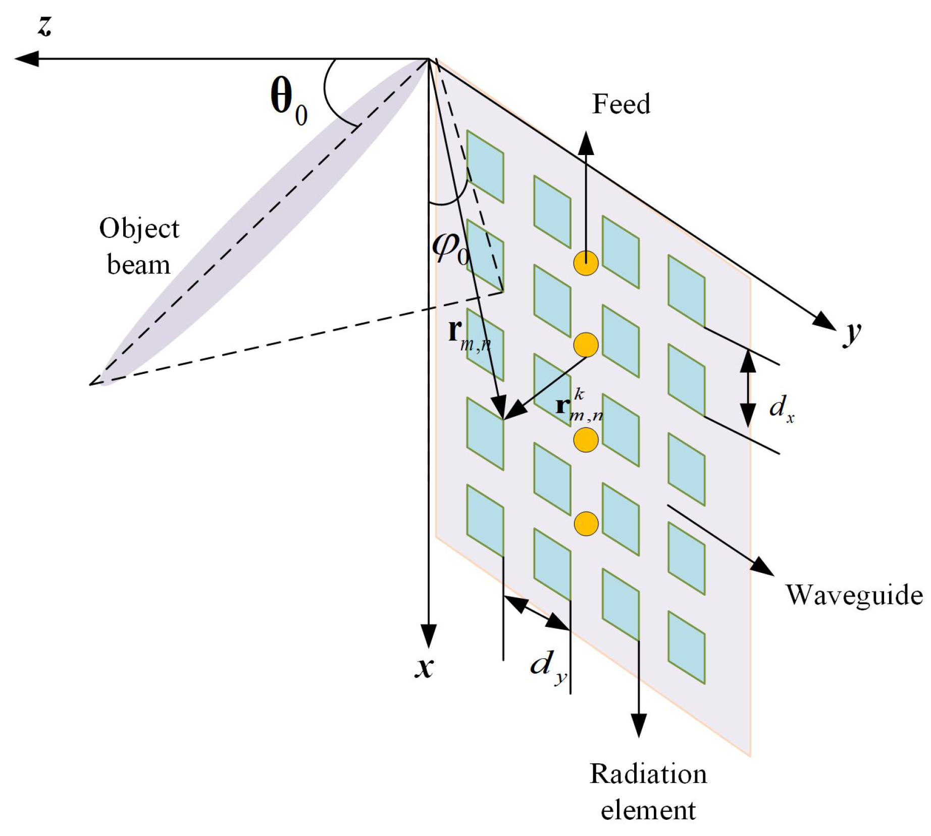
In this section, we evaluate the performance of the hybrid beamforming scheme proposed for an RHS-aided secrecy communication system through simulation results. The simulation parameters are set as follows. The element spacing of the RHS d x and d y are set as 0.25 cm. The carrier frequency f is 30 GHz, and the propagation vector on the RHS k s = 3 k f , i.e., 2 3 π f / c . The height of the BS is set as 50 m. The number of each user’s receive antennas J = 10 , as well as the noise density σ 2 = −174 dBm/Hz. We set the propagation environment between the BS and receivers as a millimeter-wave channel with I paths (we set it as one line-of-sight path and one none-line-of-sight path for simplicity). So, the the channel is denoted as
H l = X Y J I i = 1 I α l i a r ϕ r i l a t θ t i l , φ t i l H ,
where α l i is the complex gain of the i-th path; ϕ r i l and θ t i l , φ t i l are the angle of receive and transmit, respectively; and a r ϕ r i l and a t θ t i l , φ t i l are the antenna array response vectors at the receiver and transmitter [25].
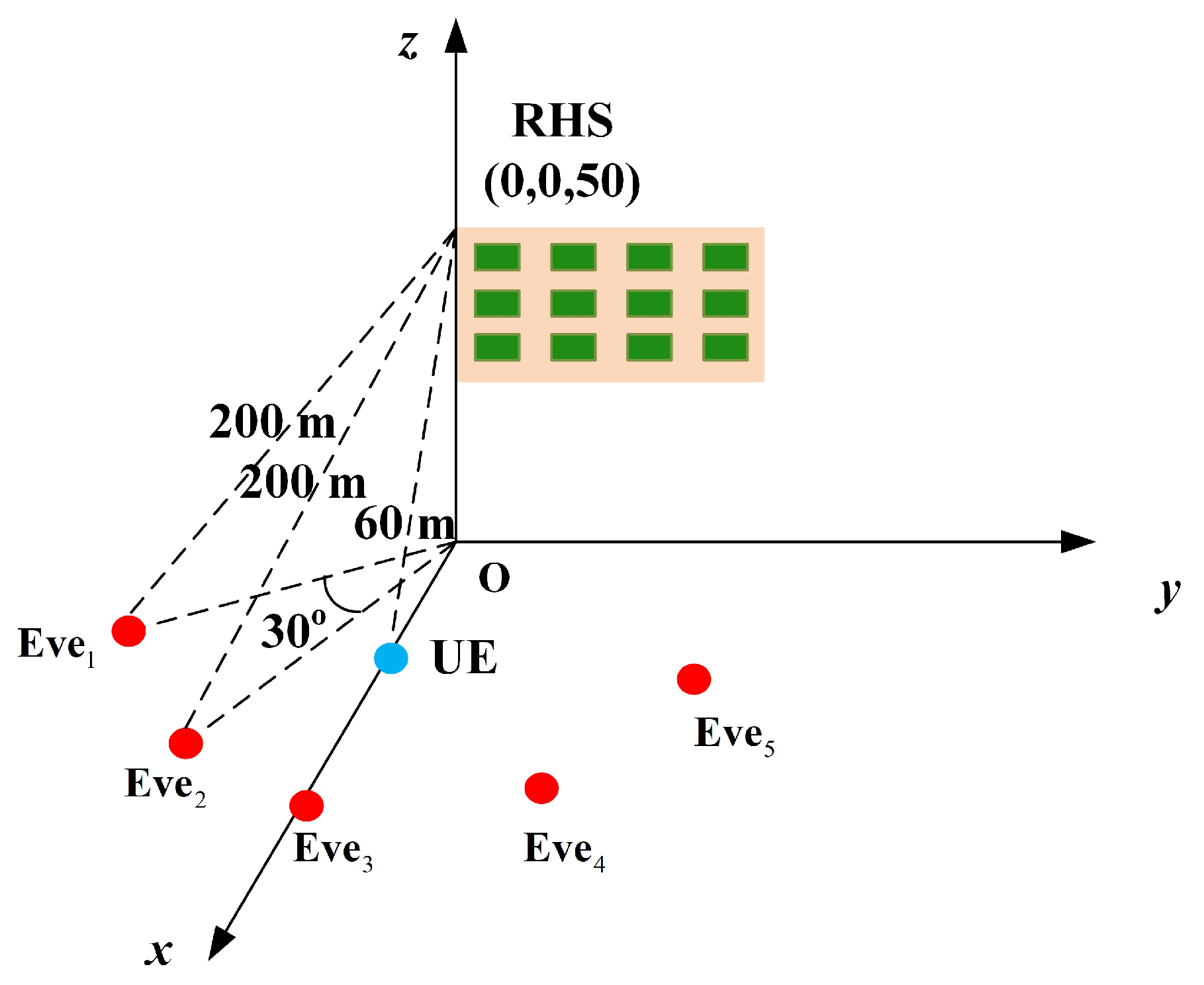
The simulation setup is depicted in Figure 3. It is assumed that the RHS is located at (0,0,50) in meters (m). UE is located on the x-axis and is 60 m away from the RHS. Five eavesdroppers are strategically deployed within the domain, with their distances from the RHS uniformly set at 200 m. The difference between the φ 0 of each eavesdropper is 30 , and they are symmetrically distributed around the UE with respect to the x-axis.
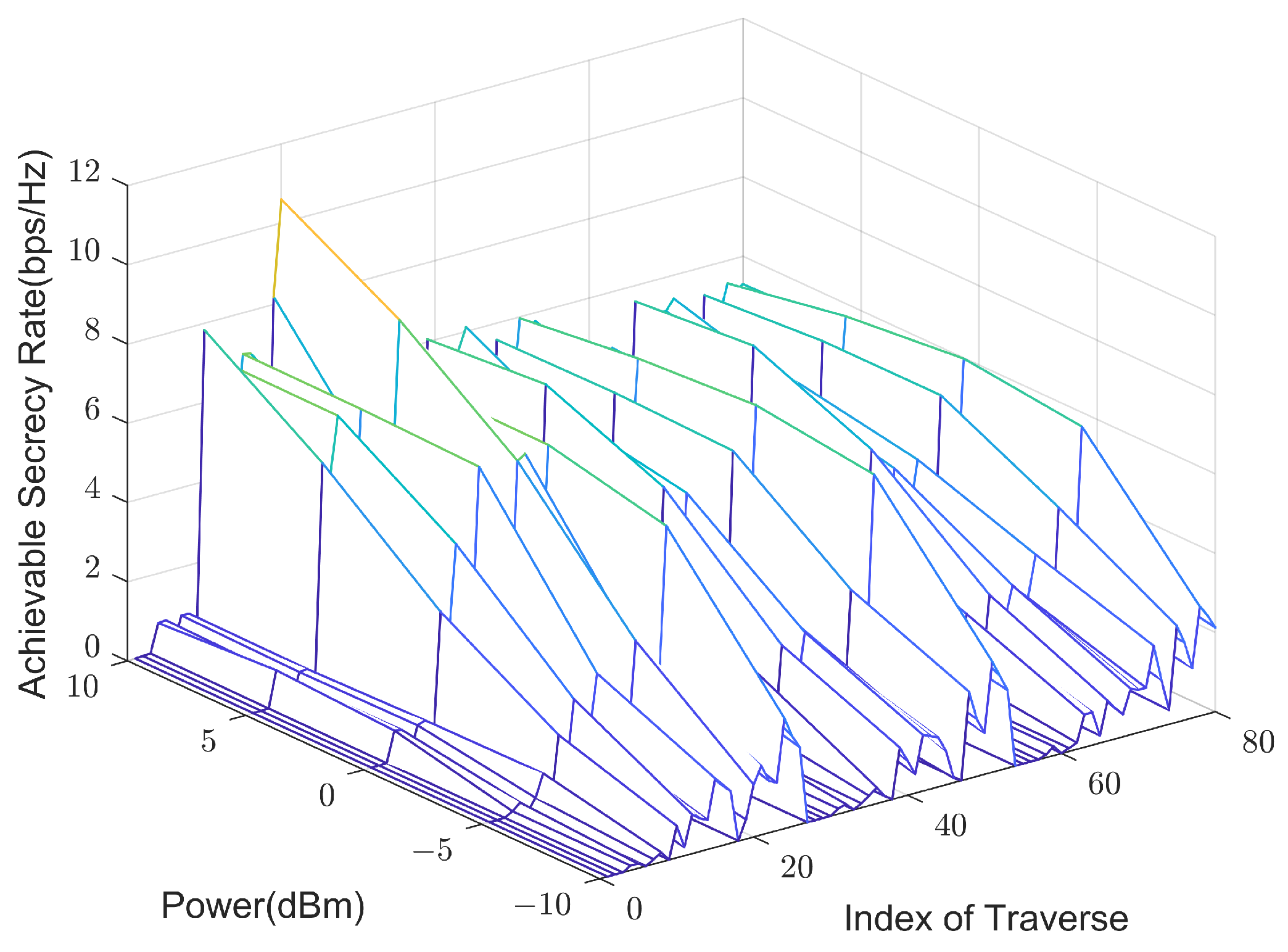
As illustrated in Figure 4, we traverse M x , y at an interval of 0.5. It can be seen that different values of M x , y influence the secrecy rate. There is a big difference in the influence of M x , y when the power is low or high. In instances of low power, the BS digital beamforming signal is slight, and optimizing M x , y primarily aims to increase the noise experienced by potential eavesdroppers. Conversely, at high power, the primary objective of M x , y optimization is to enhance receiver rates. The observed curve in the figure generally indicates that secrecy rates ascend with increased power, aligning with expected outcomes.
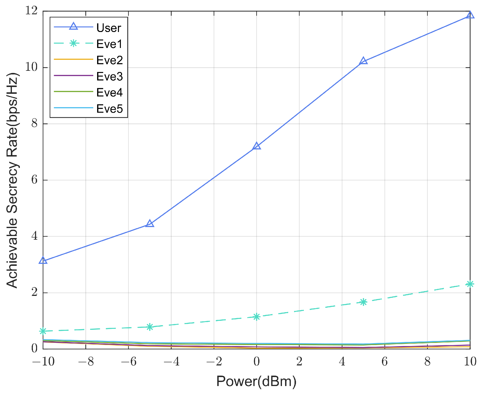
Figure 5 illustrates the communication rate of UE and Eves versus the power of the BS. It can be seen that, as the power increases, the user’s rate increases, while the eavesdropper’s rate is well suppressed. However, it is worth emphasizing that Eve1’s eavesdropping rate exhibits a higher value than the other eavesdroppers. This rate amplifies with the increase in power, which is attributed to the influence of sidelobes. RHS will generate some sidelobes when performing beamforming, and the position of Eve1 is just in the direction of sidelobe propagation, so the suppression effect of RHS on Eve1 is not as pronounced as on the other eavesdroppers.
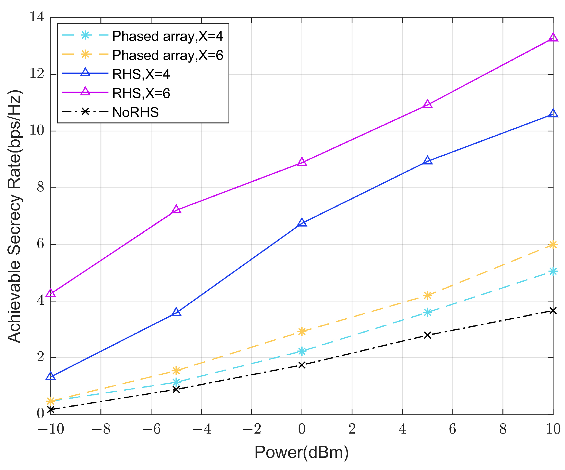
Figure 6 illustrates the secrecy rate versus the power of the BS. It can be seen that, with the increase in the transmit power, the secrecy rate is increasing. In order to show the performance of the holographic surface in secrecy communication, we have also simulated the traditional phased array and the situation without RHS. It can be seen that the communication performance of RHS is better than that of the phased array, reflecting the excellent performance of the holographic surface in terms of beamforming. We compared the effects of surfaces with different numbers of radiation elements, and we can see that the surface with more radiation elements has a higher secrecy rate because the higher spatial DoF makes the suppression effect on eavesdroppers better.
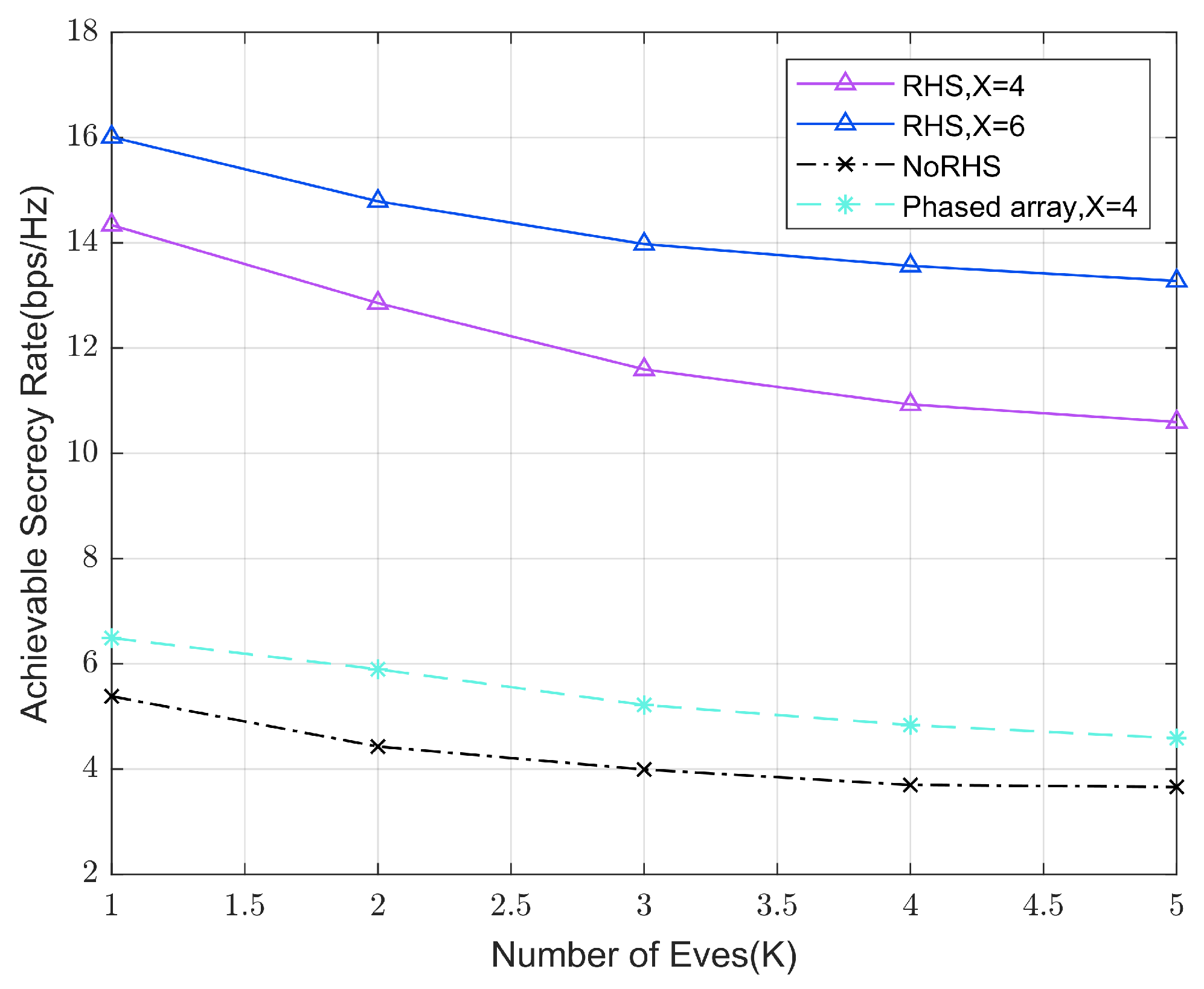
Figure 7 illustrates the secrecy rate versus the number of Eves. We set P m a x as 10 dBm. It is observable that the rate of decline is more rapid with a smaller number of Eves, and the decline will slow down when the number of Eves is large. The fundamental reason behind this phenomenon is that, when the number of Eves is small, the spatial DoF of the holographic surface plays a greater role, but as the number of Eves increases, there is a lack of sufficient spatial DoF, and artificial noise plays a major role. At first, there is a reduction in spatial DoF, and then there is a reduction only in the allocated power for each eavesdropper suppression.
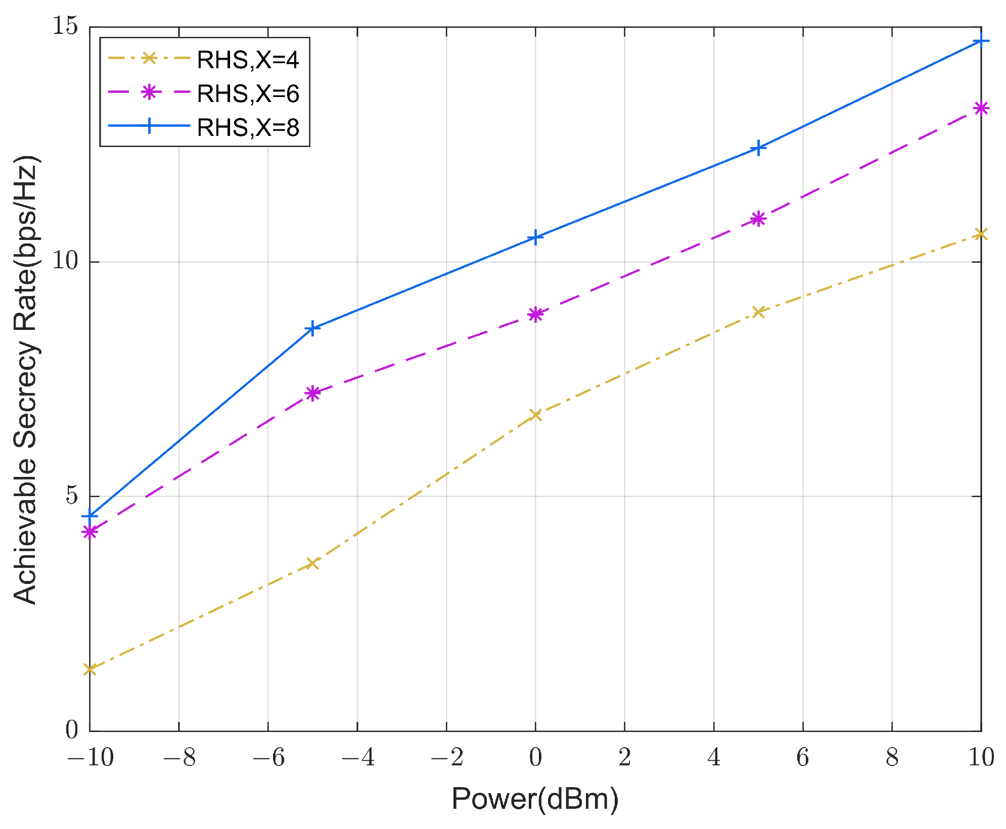
Figure 8 illustrates the secrecy rate of the RHS with different sizes versus the power of the BS. The observation can be made that a greater number of radiation elements on the holographic surface will result in a higher secrecy rate. This is expected since the Dof of the RHS will be higher with more radiation elements on the RHS; thus, the suppression against eavesdroppers will be higher. Note that, when the power is low, the secrecy rate gap between different size RHSs is different from when the power is high. This can be attributed to the fact that, at low power levels, the primary aim of beamforming is to mitigate the eavesdropper’s eavesdropping rate. When the number of radiation elements is limited to four (resulting in a low Dof on the RHS), the effectiveness of eavesdropper suppression is limited, so it is obviously lower than the secrecy rate when the size is larger. When the power is higher, the main goal is to increase the communication rate of the receiver. The drawback of low DoF at smaller sizes is alleviated by power distribution.

6. Conclusions

To enhance the RHS-aided secrecy communication system in the presence of multiple eavesdroppers, we suggested a hybrid beamforming approach in this study. We jointly designed the holographic beamforming of RHS and the digital beamforming of BS to improve the secrecy rate and create an iterative optimization algorithm. According to the simulation results, the holographic surface performs well in beam steering and has a promising future in secret communication.

Author Contributions

Conceptualization, Y.X., J.L., X.W. and T.G.; methodology, Y.X., J.L., X.W. and T.G.; validation, Y.X., J.L. and H.P.; investigation, X.W. and T.G.; writing—original draft preparation, Y.X., J.L., X.W., T.G. and H.P.; writing—review and editing, Y.X., J.L., X.W. and T.G. All authors have read and agreed to the published version of the manuscript.

Funding

This project was supported by the Postgraduate Research & Practice Innovation Program of Jiangsu Province SJCX23_0438.

Data Availability Statement

The original contributions presented in the study are included in the article. Further inquiries can be directed to the corresponding author.

Conflicts of Interest

The authors declare that they have no conflicts of interest to report regarding the present study.

Appendix A

We denote the whole holographic pattern of the holographic surface exciting the object wave propagating in the direction θ 0 , φ 0 as M θ 0 , φ 0 . According to (4), it can be denoted as follows [19]:
M θ 0 , φ 0 = Re Ψ i n t f + 1 2 = 1 2 Ψ i n t f + Ψ i n t f ¯ + 1 2 = 1 4 Ψ o b j Ψ r e f ¯ + 1 4 Ψ o b j ¯ Ψ r e f + 1 2 .
Then, when the reference wave reaches the radiation elements, the energy excited by the holographic pattern into free space can be expressed as follows:
M θ 0 , φ 0 Ψ r e f = 1 4 Ψ o b j Ψ r e f 2 + 1 4 Ψ o b j ¯ Ψ r e f 2 + 1 2 Ψ r e f = 1 4 Ψ r e f 2 Ψ o b j + Ψ o b j 1 4 Ψ o b j ¯ Ψ r e f 2 + 1 2 Ψ o b j ¯ Ψ r e f .
The above equation is the energy distribution of the excited object wave in free space. The first half of the equation is the object wave in the desired direction, and the second half represents the sidelobes generated by the RHS. In order to offset sidelobes, Ψ r e f needs to satisfy the following equation:
Im 1 4 Ψ o b j ¯ Ψ r e f 2 + 1 2 Ψ o b j ¯ Ψ r e f = 0 x , y e j 2 k f · r x , y k s · r x , y k + 2 e j k f · r x , y k s · r x , y k = 0 .
The above formula is related to the position of feeds, so sidelobes can be suppressed by adjusting the position of feeds.

References

  1. Zhang, S.; Liu, J.; Guo, H.; Qi, M.; Kato, N. Envisioning device-to-device communications in 6G. IEEE Netw. 2020, 34, 86–91. [Google Scholar] [CrossRef]
  2. Wang, D.; Zhang, Y.; Wei, H.; You, X.; Gao, X.; Wang, J. An overview of transmission theory and techniques of large-scale antenna systems for 5G wireless communications. Sci. China Inf. Sci. 2016, 59, 081301. [Google Scholar] [CrossRef]
  3. Wu, Q.; Zhang, R. Towards smart and reconfigurable environment: Intelligent reflflecting surface aided wireless network. arXiv 2019, arXiv:00152. [Google Scholar] [CrossRef]
  4. Wu, Q.; Zhang, R. Weighted sum power maximization for intelligent reflflecting surface aided swipt. arXiv 2019, arXiv:1907.05558. [Google Scholar]
  5. Wu, Q.; Zhang, R. Beamforming optimization for wireless network aided by intelligent reflflecting surface with discrete phase shifts. arXiv 2019, arXiv:1906.03165. [Google Scholar]
  6. Wu, Q.; Zhang, R. Intelligent reflflecting surface enhanced wireless network via joint active and passive beamforming. arXiv 2019, arXiv:1810.03961. [Google Scholar]
  7. Wu, Q.; Zhang, S.; Zheng, B.; You, C.; Zhang, R. Intelligent Reflecting Surface-Aided Wireless Communications: A Tutorial. IEEE Trans. Commun. 2021, 69, 3313–3351. [Google Scholar] [CrossRef]
  8. Yu, X.; Xu, D.; Schober, R. Enabling secure wireless communications via intelligent reflflecting surfaces. arXiv 2019, arXiv:09573. [Google Scholar]
  9. Shen, H.; Xu, W.; Gong, S.; He, Z.; Zhao, C. Secrecy rate maximization for intelligent reflflecting surface assisted multi-antenna communications. arXiv 2019, arXiv:10075. [Google Scholar]
  10. Chen, J.; Liang, Y.-C.; Pei, Y.; Guo, H. Intelligent reflflecting surface: A programmable wireless environment for physical layer security. arXiv 2019, arXiv:03689. [Google Scholar]
  11. Fong, B.H.; Colburn, J.S.; Ottusch, J.J.; Visher, J.L.; Sievenpiper, D.F. Scalar and tensor holographic artifificial impedance surfaces. IEEE Trans. Antennas Propag. 2010, 58, 3212–3221. [Google Scholar] [CrossRef]
  12. Yurduseven, O.; Smith, D.R. Dual-polarization printed holographic multibeam metasurface antenna. IEEE Antennas Wirel. Propag. Lett. 2017, 16, 2738–2741. [Google Scholar] [CrossRef]
  13. Johnson, M.C.; Brunton, S.L.; Kundtz, N.B.; Kutz, J.N. Sidelobe canceling on a reconfigurable holographic metamaterial antenna. In Proceedings of the International Conference on Electromagnetics in Advanced Applications, Palm Beach, FL, USA, 3–8 August 2014; pp. 806–809. [Google Scholar]
  14. Deng, R.; Di, B.; Zhang, H.; Niyato, D.; Han, Z.; Poor, H.V.; Song, L. Reconfigurable holographic surfaces for future wireless communications. IEEE Wirel. Commun. 2021, 28, 126–131. [Google Scholar] [CrossRef]
  15. Yurduseven, O.; Marks, D.L.; Gollub, J.N.; Smith, D.R. Design and analysis of a reconfigurable holographic metasurface aperture for dynamic focusing in the Fresnel zone. IEEE Access 2017, 5, 15055–15065. [Google Scholar] [CrossRef]
  16. Sleasman, T.; Imani, M.F.; Xu, W.; Hunt, J.; Driscoll, T.; Reynolds, M.S.; Smith, D.R. Waveguide-fed tunable metamaterial element for dynamic apertures. IEEE Antennas Wirel. Propag. Lett. 2016, 15, 606–609. [Google Scholar] [CrossRef]
  17. Deng, R.; Di, B.; Zhang, H.; Tan, Y.; Song, L. Reconfigurable holographic surface: Holographic beamforming for metasurface-aided wireless communications. IEEE Trans. Veh. Technol. 2021, 70, 6255–6259. [Google Scholar] [CrossRef]
  18. Deng, R.; Di, B.; Zhang, H.; Song, L. HDMA: Holographic-pattern division multiple access. IEEE J. Sel. Areas Commun. 2022, 40, 1317–1332. [Google Scholar] [CrossRef]
  19. Deng, R.; Di, B.; Zhang, H.; Tan, Y.; Song, L. Reconfigurable holographic surface-enabled multi-user wireless communications: Amplitude-controlled holographic beamforming. IEEE Trans. Wirel. Commun. 2022, 21, 6003–6017. [Google Scholar] [CrossRef]
  20. Deng, R.; Di, B.; Zhang, H.; Poor, H.V.; Song, L. Holographic MIMO for LEO satellite communications aided by reconfigurable holographic surfaces. IEEE J. Sel. Areas Commun. 2022, 40, 3071–3085. [Google Scholar] [CrossRef]
  21. Deng, R.; Zhang, Y.; Zhang, H.; Di, B.; Zhang, H.; Song, L. Reconfigurable holographic surface: A new paradigm to implement holographic radio. IEEE Veh. Technol. Mag. 2023, 18, 20–28. [Google Scholar] [CrossRef]
  22. Guan, X.; Wu, Q.; Zhang, R. Intelligent reflecting surface assisted secrecy communication: Is artificial noise helpful or not? IEEE Wirel. Commun. Lett. 2020, 9, 778–782. [Google Scholar] [CrossRef]
  23. Li, Q.; Hong, M.; Wai, H.-T.; Liu, Y.-F.; Ma, W.-K.; Luo, Z.-Q. Transmit solutions for MIMO wiretap channels using alternating optimization. IEEE J. Sel. Areas Commun. 2013, 31, 1714–1727. [Google Scholar] [CrossRef]
  24. Sion, M. On general minimax theorems. Pac. J. Math. 1958, 8, 171–176. [Google Scholar] [CrossRef]
  25. Sohrabi, F.; Yu, W. Hybrid digital and analog beamforming design for large scale MIMO systems. In Proceedings of the 2015 IEEE International Conference on Acoustics, Speech and Signal Processing (ICASSP), Brisbane, QLD, Australia, 19–24 April 2015; pp. 2929–2933. [Google Scholar]
Figure 1. RHS-aided secrecy communication system.
Electronics 13 01359 g001
Figure 2. Reconfigurable holographic surface.
Electronics 13 01359 g002
Figure 3. Simulation setups.
Electronics 13 01359 g003
Figure 4. The secrecy rate versus the amplitude of the RHS.
Electronics 13 01359 g004
Figure 5. The rates of UE and each Eve versus the power of the RHS.
Electronics 13 01359 g005
Figure 6. The secrecy rate versus the power of the RHS.
Electronics 13 01359 g006
Figure 7. The secrecy rate versus the number of Eves.
Electronics 13 01359 g007
Figure 8. The secrecy rate versus the size of the Eves.
Electronics 13 01359 g008
Disclaimer/Publisher’s Note: The statements, opinions and data contained in all publications are solely those of the individual author(s) and contributor(s) and not of MDPI and/or the editor(s). MDPI and/or the editor(s) disclaim responsibility for any injury to people or property resulting from any ideas, methods, instructions or products referred to in the content.

