Energy-Efficient Partial LDPC Decoding for NAND Flash-Based Storage Systems


School of Electrical Engineering, Korea Advanced Institute of Science and Technology (KAIST), Daejeon 34141, Republic of Korea
Electronics 2024, 13(7), 1392; https://doi.org/10.3390/electronics13071392
Submission received: 28 February 2024
/
Revised: 31 March 2024
/
Accepted: 4 April 2024
/
Published: 7 April 2024
(This article belongs to the Section Circuit and Signal Processing)
Abstract
:A new decoding method for low-density parity-check (LDPC) codes is presented to lower the energy consumption of LDPC decoders for NAND flash-based storage systems. Since the channel condition of NAND flash memory is reliable for most of its lifetime, it is inefficient to apply the maximum-effort decoding with the full parity-check matrix (H-matrix) from the beginning of the lifespan. As the energy consumption and the decoding latency are proportional to the size of the H-matrix used in decoding, the proposed algorithm starts the decoding with a partial H-matrix selected by considering the channel condition. In addition, the proposed partial decoding provides various error-correcting capabilities by adjusting the partial H-matrix. Based on the proposed partial decoding algorithm, a prototype decoder is implemented in a 65 nm CMOS process to decode a 4 KB LDPC code. The proposed decoder reduces energy consumption by 93% compared to the conventional LDPC decoding architecture at maximum.
1. Introduction
NAND flash memory is extensively used in many storage solutions, such as solid-state drives (SSDs) and secure digital (SD) cards, due to its fast accessibility, low-power consumption, and compact size [1,2]. Recently, advanced structures such as 3D-stacked NAND flash for storing more information in a limited area have been widely employed, which provide a more error-prone environment [3,4,5]. In storage systems built with NAND flash memories, error-correction codes (ECCs) are commonly applied to ensure data reliability. Algebraic codes such as BCH and RS codes have widely been employed because of their guaranteed performance and moderate hardware complexity, but the codes are not adequate when the NAND flash channel worsens. For that reason, the LDPC code has been employed in many NAND flash-based storage systems recently, as its error-correcting capability resulting from iterative belief propagation is far superior to the algebraic codes. However, the LDPC decoding necessitates high computational complexity and frequent memory accesses, and consumes considerably higher energy than BCH and RS decoding processes [6,7].
Since the NAND flash channel is reliable for most of its lifetime, the maximum-effort decoding with the full parity-check matrix (H-matrix) is inefficient when the channel is reliable. Providing multiple error-correcting capabilities may be a solution, since the error-correcting capability can be adjusted depending on the channel condition. As a matter of fact, multi-rate LDPC codes are commonly used to provide various error-correcting capabilities in the wireless communication systems [8,9]. The use of multi-rate codes is effective only when the channel condition at the time of encoding is consistent with that of decoding, which means that the traditional multi-rate codes are not suitable for storage systems in which the data writes and reads can occur far apart.
A new partial decoding is proposed to provide various error-correcting capabilities with a single H-matrix. The decoding strength is adjusted by changing the column degree of the partial H-matrix, which is verified through intensive simulations over the additive white Gaussian noise (AWGN) channel. Based on partial decoding, we present a novel energy-efficient decoding algorithm. The proposed algorithm starts the decoding with a partial H-matrix selected by considering the channel condition at the time of decoding. When the decoding with the partial H-matrix fails, the proposed algorithm increases the size of the partial H-matrix to enhance the decoding strength and tries the decoding again. Since the energy consumption of an LDPC decoder is mainly related to the size of the H-matrix used for decoding, the proposed algorithm can reduce the energy consumed in the decoding process. In addition, it is effective in reducing the decoding latency and enhancing the decoding throughput.
The rest of this paper is organized as follows. Section 3 introduces the proposed partial decoding of the LDPC codes and Section 4 analyzes simulation results of the proposed energy-efficient decoding algorithm. Theoretical analysis is explained in Section 5. The details of the hardware design and the implementation results are presented in Section 6 and Section 7, respectively, and conclusions are made in Section 8.
2. Backgrounds
This section provides an overview of LDPC decoding algorithms, including an in-depth explanation of the Sum-Product algorithm (SPA) [10] and that of the Min-Sum algorithm (MSA) [11]. Moreover, the structure of the Quasi-Cyclic (QC) LDPC H-matrix will be introduced to explain proposed algorithms.
2.1. LDPC Decoding Algorithms
The SPA and the MSA are two prominent methods used for decoding LDPC codes, which are essential for error correction in NAND flash-based storage systems. They are also known as the Belief Propagation (BP) algorithms of LDPC codes. It operates by passing probabilistic messages along the edges of a Tanner graph to estimate the likelihood of bit values. Both algorithms operate iteratively decoding the likelihood messages until they converge to a stable solution or reach a predefined number of iterations. In each iteration, the SPA combines the messages from neighboring nodes using a product operation, followed by a normalization process to update the beliefs of each bit’s value. In contrast, the MSA estimates these probabilities by considering the minimum value of the incoming messages, hence the name. This method, while an approximation, significantly reduces the need for complex calculations without drastically affecting decoding accuracy. The SPA typically requires floating-point precision and involves trigonometric functions, making it computationally intensive.
The advantage of using MSA lies in its simplicity, as it can be implemented using integer arithmetic and simple comparison operations, making it suitable for hardware with limited processing capabilities. Both algorithms benefit from the inherent error detection and correction capabilities of LDPC codes, which feature a redundant structure enabling the identification and rectification of errors in data transmission. The practical implementation of these algorithms also considers factors such as channel noise characteristics and the required level of error correction. Tailoring the algorithm to specific needs can result in various modifications and optimizations, such as the normalized MSA and the offset MSA, which aim to bridge the performance gap with the SPA.
2.2. Quasi-Cyclic LDPC Codes
The array LDPC code is suitable for adjusting the column degree of the H-matrix, as it is one of regular LDPC codes that have fixed column and row degrees. Moreover, it is one of the quasi-cyclic (QC) LDPC codes composed of shifted identity matrices of the same size [12]. Therefore, the number of check nodes can be controlled easily by eliminating some block-rows, each of which having the same size as the identity matrix. Three parameters, , , and p, define an array LDPC code, where p is a prime number denoting the size of the identity matrix, and and represent the column and row degrees of the H-matrix, respectively. The H-matrix of the array LDPC code is
where I is the identity matrix and A is a matrix obtained by shifting every row of I cyclically by one. When , for example, the corresponding matrix A is
Based on (2), is calculated as
3. Proposed Partial Decoding of LDPC Codes
The partial decoding of an LDPC code is newly introduced to provide various error-correcting capabilities, which can be adaptively applied according to the channel condition. The decoding strength is adjusted by changing the number of check nodes to be used for decoding. The number of check nodes relevant to a variable node is called the column degree of the H-matrix. Since each variable node collects the local messages come from the connected check nodes, the LDPC decoding works normally with some check nodes removed. Therefore, the error-correcting capability can be adjusted by changing the column degree.
3.1. Construction of a Partial H-Matrix
The H-matrix shown in (1) can be decomposed into sub-matrices, to ,
where is a sub-matrix denoting
To support various error-correcting capabilities, a partial H-matrix is organized by including some of the above sub-matrices, to . A set of sub-matrices is denoted as ,
where x is an integer ranging from 2 to , since the column degree of a partial H-matrix should be at least 2 in order to decode an LDPC code. When , for example, a partial H-matrix is constructed as
3.2. Decoding of a Partial H-Matrix
The message is encoded with the full H-matrix of the LDPC code, while the received codeword is decoded by using a partial H-matrix in the partial decoding. Iterative decoding algorithms such as the SPA or MSA can be used to update variable nodes and check nodes based on the partial H-matrix. Before starting a decoding iteration using the partial H-matrix, the syndromes of the updated codeword are checked with respect to the full H-matrix. If the syndromes are all zeros, then the codeword is correct so that the decoding process is finished. Otherwise, we repeat the decoding iteration until we reach the number of maximally allowed iterations (MAI). The detailed procedure of the partial decoding is described in Algorithm 1.
| Algorithm 1 Partial LDPC decoding. | |
| 1: Initialization: load the initial LLR values to each variable node. | |
| 2: Iterative Decoding: Perform the following steps in accordance with the SPA or MSA. | |
| 3: for to do | ▹ Iterative decoding |
| 4: for all check nodes included in the full H, do | ▹ Syndrome check |
| 5: compute syndrome | |
| 6: end for | |
| 7: if syndromes are all zeros then | ▹ Decoding success |
| 8: report a decoding success do terminate the decoding | |
| 9: end if | |
| 10: for check nodes included in the partial H, do | ▹ Check node update |
| 11: update check nodes and generate check-to-variable node (C2V) messages | |
| 12: end for | |
| 13: for all variable nodes do H, do | ▹ Variable node update |
| 14: update LLR values and generate variable-to-check node (V2C) messages | |
| 15: end for | |
| 16: end for | |
| 17: report a decoding failure | ▹Decoding failure |
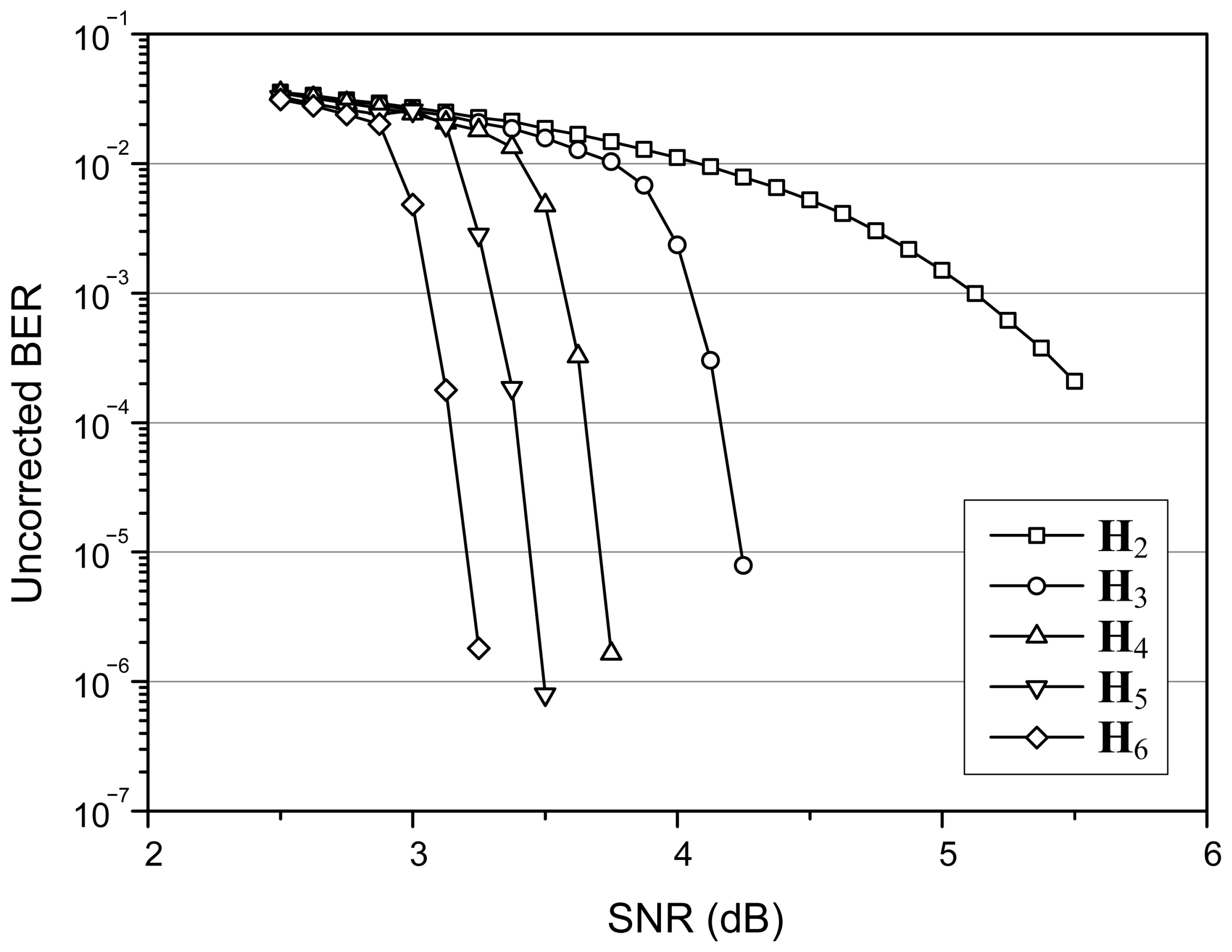
The error-correcting capability resulting from a partial H-matrix is investigated based on a (149, 61, 6) array LDPC code that is designed to protect a message of 1 KB. The SPA is employed to decode the received codeword with setting MAI to 30. Figure 1 shows how the error-correcting capability changes over the channel SNR. The uncorrected bit-error rate (BER) performances resulting from and correspond to the weakest and strongest error-correcting capabilities, respectively. The decoding strength is stronger when the partial H-matrix becomes larger. Therefore, it is possible to support diverse error-correcting capabilities by constructing several partial H-matrices from a single H-matrix. Though shows the weakest decoding strength, it removes two thirds of memory accesses compared to the full H-matrix. This enables a tradeoff between decoding capability and energy consumption, since the number of memory accesses dominates the energy consumption of an LDPC decoder [13].
3.3. Proposed Energy-Efficient Decoding of a Partial H-Matrix
The proposed decoding algorithm increases energy efficiency in the LDPC decoding, and is effective in reducing the energy consumption of storage systems built with NAND flash memory, since the NAND flash is reliable in the beginning stage. Applying high voltages to a cell repeatedly to program or erase the cell decreases the SNR of the flash channel monotonically [3,4]. As the wear-leveling technique makes the SNR of a page almost the same as that of the other page [5], the NAND flash channel is reliable in a considerable amount of time. Since the NAND flash channel in the beginning does not induce many erroneous bits, the maximum-effort decoding with the full H-matrix is inefficient. Therefore, the proposed algorithm selects a proper partial H-matrix depending on the channel condition.
Considering the channel SNR, the proposed algorithm selects a specific partial matrix from a set of partial H-matrices defined as
The selected partial H-matrix is the initial partial H-matrix that is first used for decoding. The initial partial H-matrix for a specific SNR can be determined in advance by conducting simulations over the flash channel or by analyzing the decoding algorithm. The proposed energy-efficient decoding algorithm is described in Algorithm 2.
| Algorithm 2: Energy-efficient LDPC decoding. |
|
4. Simulation Results
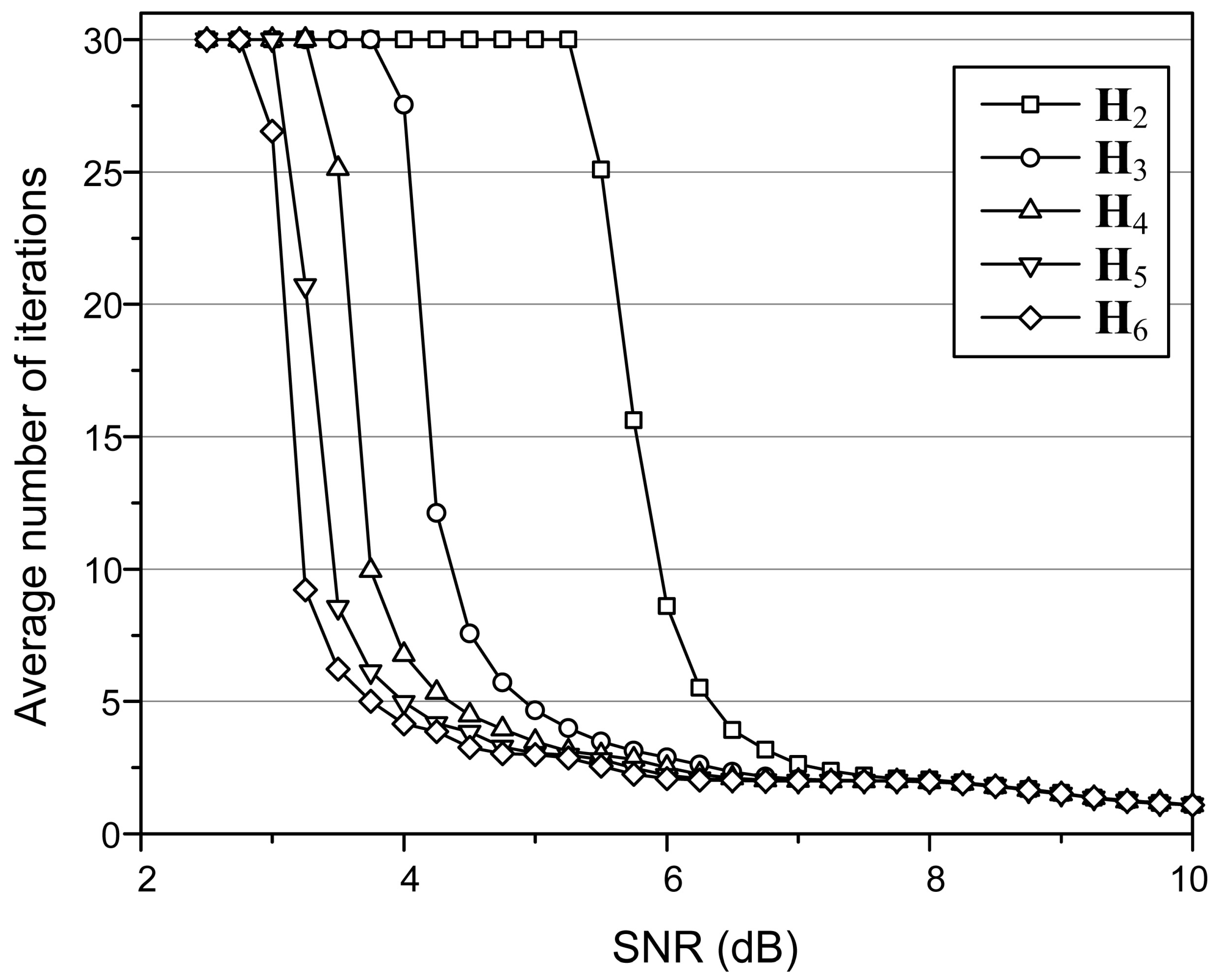
The (149, 61, 6) array LDPC code is used to validate the proposed energy-efficient LDPC decoding algorithm. The average number of iterations required to decode a codeword is shown in Figure 2, which is obtained by applying the SPA with setting the MAI to 30. In the simulation, the flash memory is regarded as an AWGN channel. The SNR is defined as , where N is the noise power, and is the signal power. It is assumed that the distribution for a Single Level Cell is similar to that of Binary Phase Shift Keying (BPSK). The Error Rate was considered based on the assumption that an all-zero code transmitted as ‘1’ would result in an error if the outcome was non-zero.
For a specific SNR, there are partial H-matrices that provide almost the same decoding performance as that of the full H-matrix. For an SNR of 6 dB, for example, the decoding with leads to almost the same number of iterations as that of the full H-matrix. Based on the simulation results, the proposed algorithm selects an initial partial H-matrix with which the decoding starts. Decoding may continue with , but if the average number of iterations begins to increase, it can switch to decoding with . This inference is exploited by simulation results, and implementation is feasible through an SSD controller that tracks the number of iterations at the end of the previous decoding process.
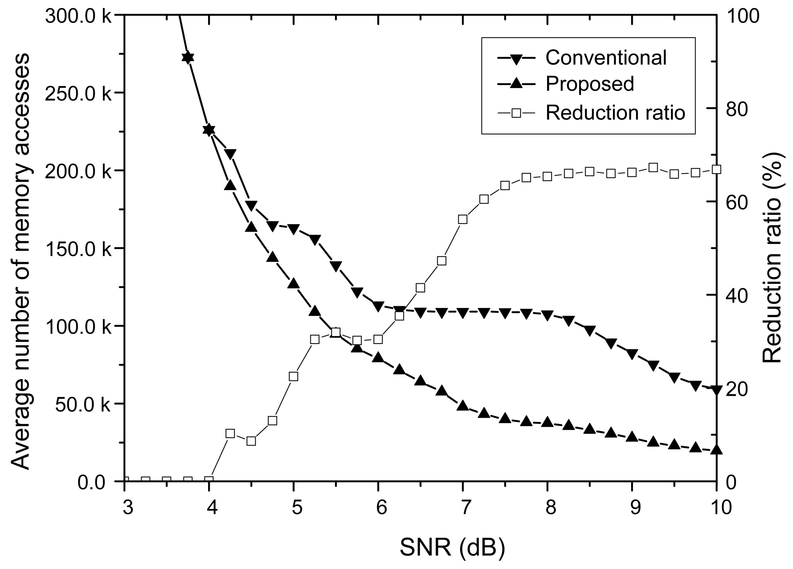
The energy consumption of an LDPC decoder is mainly dominated by memory accesses resulting from frequent updates of internal messages to be exchanged between variable and check nodes [13]. Reducing the number of memory accesses is therefore highly effective in lowering the overall energy consumption. Moreover, it decreases the decoding latency as well as the decoding throughput. As the number of memory accesses is proportional to the size of the H-matrix used in decoding, reducing its size lessens the energy consumed in the LDPC decode in effect. The average number of memory accesses resulting from the proposed partial decoding algorithm and the conventional one that decodes with the full H-matrix are compared in Figure 3. It is clear that the proposed algorithm considerably reduces the number of memory accesses when the SNR is not small. Since the large number of memory accesses leads to high energy consumption, the proposed decoding algorithm significantly reduces the energy consumed in the high SNR region.
For the (149, 61, 6) array LDPC code, the energy consumption caused by memory accesses is reduced down to 33.1% even compared to the conventional decoding algorithm that employs the early stopping method [14]. As the memory accesses are mainly required to calculate V2C and C2V messages, the computational operations are also reduced in proportion to the reduction ratio of memory accesses, which means that the energy consumption of the LDPC decoder can be reduced by the reduction ratio of memory accesses.
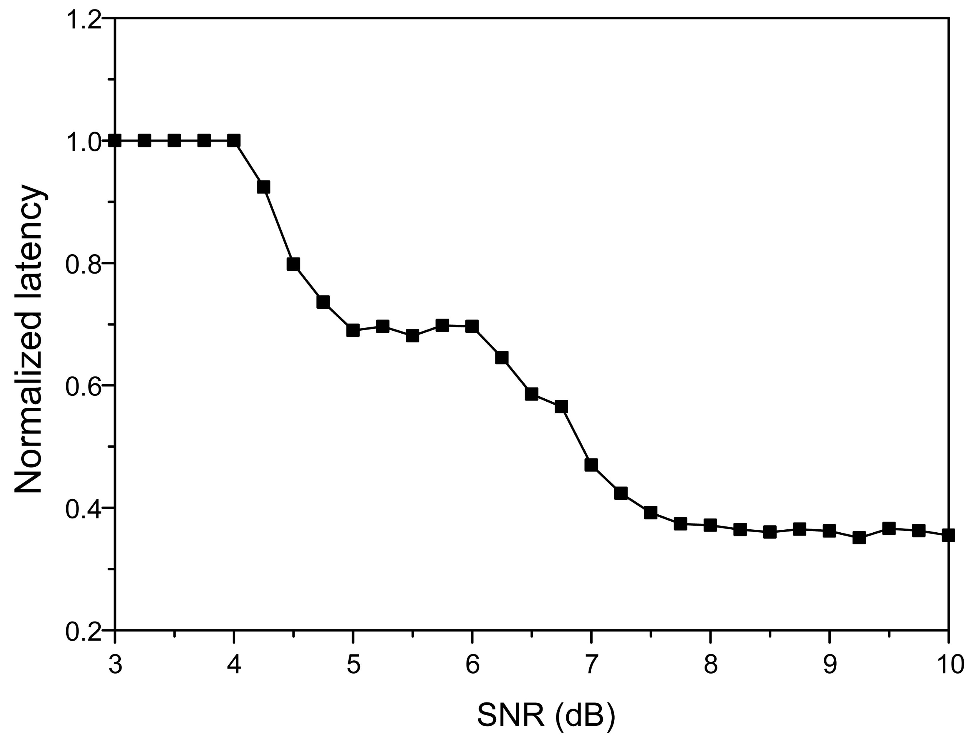
In addition, both the decoding latency and the decoding throughput are enhanced. The normalized latency of the proposed partial decoding algorithm is compared to the conventional one in Figure 4. Since the number of variable nodes connected to each check node is constant, the number of clock cycles taken to process a check node is constant for all partial H-matrices. Therefore, the number of check node operations affects the decoding latency. As the number of check node operations is proportional to the size of the partial H-matrix, the decoding latency can be effectively reduced by reducing the size. In Figure 4, the decoding latency is reduced to 35.5% at maximum compared to the conventional architecture [15]. Since the decoding throughput is inversely proportional to the decoding latency, the proposed partial decoding algorithm can boost the decoding throughput significantly in the beginning stage.
5. Theoretical Analysis
The proposed decoding algorithm is theoretically analyzed to explain the existence of a partial H-matrix that results in almost the same decoding performance as the full H-matrix. It will be shown that the theoretical prediction of the required number of iterations is consistent with the simulation results. The partial H-matrix can be determined by looking into the number of iterations. To calculate the number of iterations required for a specific SNR theoretically, we estimate how the BER of the decoded outputs changes according to decoding iterations. The LLR distribution obtained by the internal message tracking technique, which is called density evolution in [16], is used to estimate the BER of the decoded outputs. The distribution of the LLR values over all variable nodes is investigated in each iteration. The SPA is assumed for this analysis, as the internal steps of the algorithm can be described in mathematically closed forms.
5.1. Calculation of the LLR Distribution
The LLR distribution in the l-th iteration is analyzed by using the mathematically closed forms of the SPA. For an H-matrix , the set of variable nodes connected to the m-th check node is denoted as
where represents the element of the H-matrix on the m-th row and n-th column. Similarly, the set of check nodes connected to the n-th column is
If a regular LDPC code is considered in the analysis, the numbers of elements in and are and , respectively. The set that excludes element n from is denoted as , and the set excluding m from is similarly denoted as . The LLR value of the n-th variable node after l iterations is denoted as , and similarly the C2V message of the m-th check node after l iterations is represented as . The means of and for all n and m are denoted as and , respectively.
In previous works [16,17], the distribution of for all n is known to be binomially distributed as [16], where represents the Gaussian distribution with mean and variance , and is also binomially distributed [17]. Therefore, the LLR distribution can be obtained by tracking in each iteration. The equations that update variable and check nodes are used to chase the mean of the LLR distribution. In the SPA, the variable node update is expressed as
where is the initial LLR. The corresponding C2V message for the l-th iteration is
For convenience, Equation (12) is rewritten as
Taking the expectations for both sides,
For the sake of simple expression, is defined as
where . Equation (14) can be rewritten as
Taking the expectations for both sides of (11), we obtain
where is the energy consumed to transmit a bit of a codeword and is the standard deviation of the AWGN channel. A bit of zero or one transmitted over the AWGN channel is mapped to or , respectively, and the all-zero codeword is assumed to be sent. By substituting (17) into (16), we have
and it is rewritten as
By substituting Equation (19) into Equation (17), we finally have the mean of the LLR distribution,
where can be recursively calculated from (19) with the initial condition of . The mean of LLR distribution is only determined by the column degree , the row degree , and the channel SNR . Therefore, the LLR distribution after l iterations can be estimated from the mean expressed in (20).
5.2. Calculation of the Number of Iterations
For a specific SNR, the LLR values of all variable nodes are distributed following the binomial distribution of [16]. The mean of the LLR distribution is obtained from (20) by adjusting the column degree according to the size of the partial H-matrix. To decide the success or failure of the decoding, the BER is estimated from the calculated LLR distribution.
Assuming that the transmitted codeword are all zeros, the correctly decoded codeword has positive LLR values for all bit-positions, but the uncorrected codeword has some negative LLR values. Therefore, the ratio of the negative area to the total area of the distribution can be considered as the uncorrected BER for a specific number of iterations. Since the LLR values are binomially distributed, the BER after l iterations is calculated as
where is the Q-function of the given distribution,
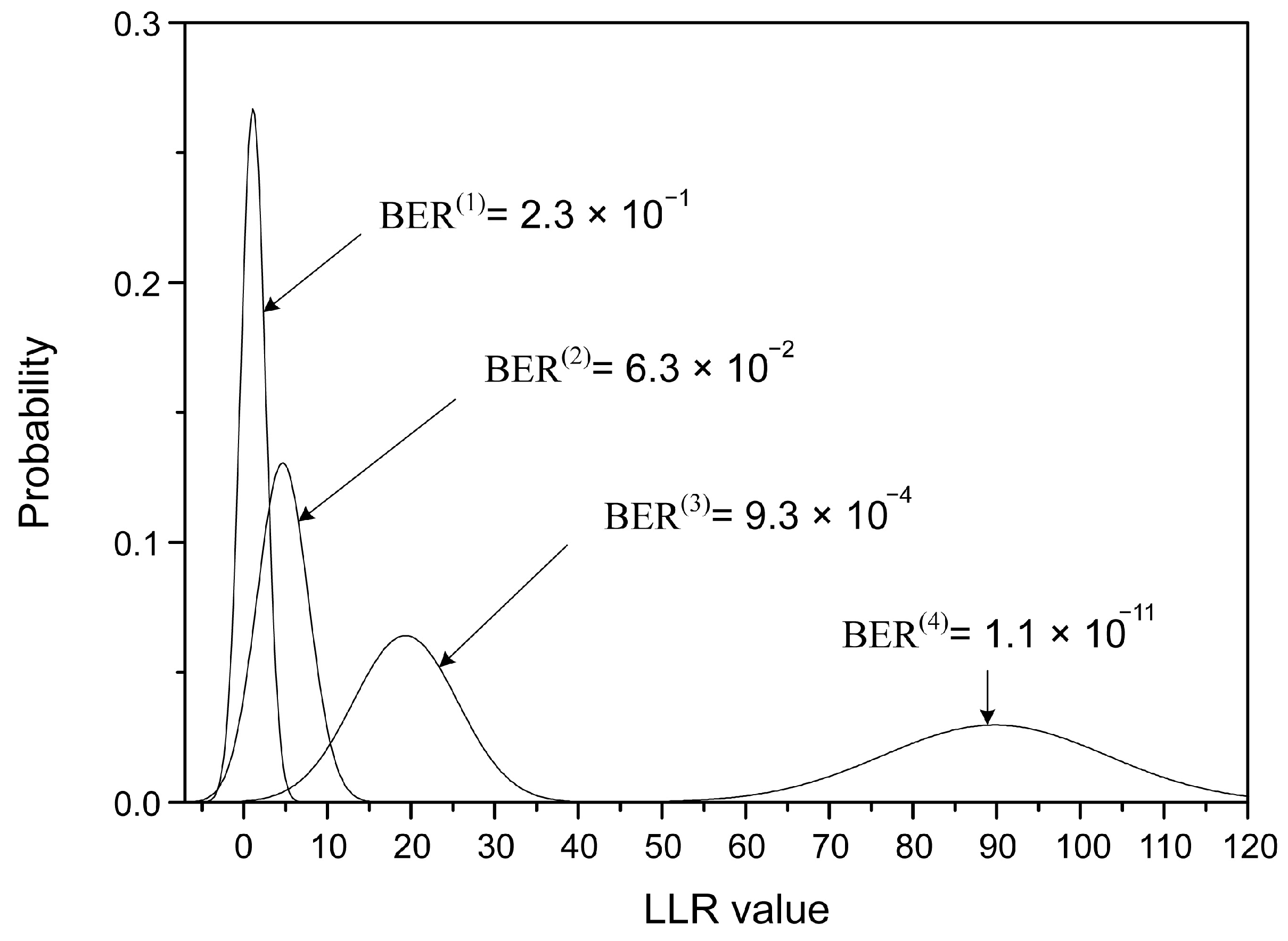
The LLR distribution and the estimated BER for the (149, 61, 6) array LDPC code with an SNR of 5dB is shown in Figure 5. The full H-matrix is used for decoding, which means that is 6. As the number of iterations increases, the mean of the LLR distribution moves to the higher value, leading to a reduced BER. The estimated BER is used to compute the number of iterations needed to achieve successful decoding. It is assumed that the left tail of the BER distribution in Figure 5, which falls into the negative region, represents the proportion of errors relative to the total number of cases. The area of that tail was calculated using the Q-function, as described in (21) to determine the BER value. When the calculated BER is less than in a certain iteration, which is a criterion widely accepted in the storage market, the decoding is considered to be successful in that iteration.
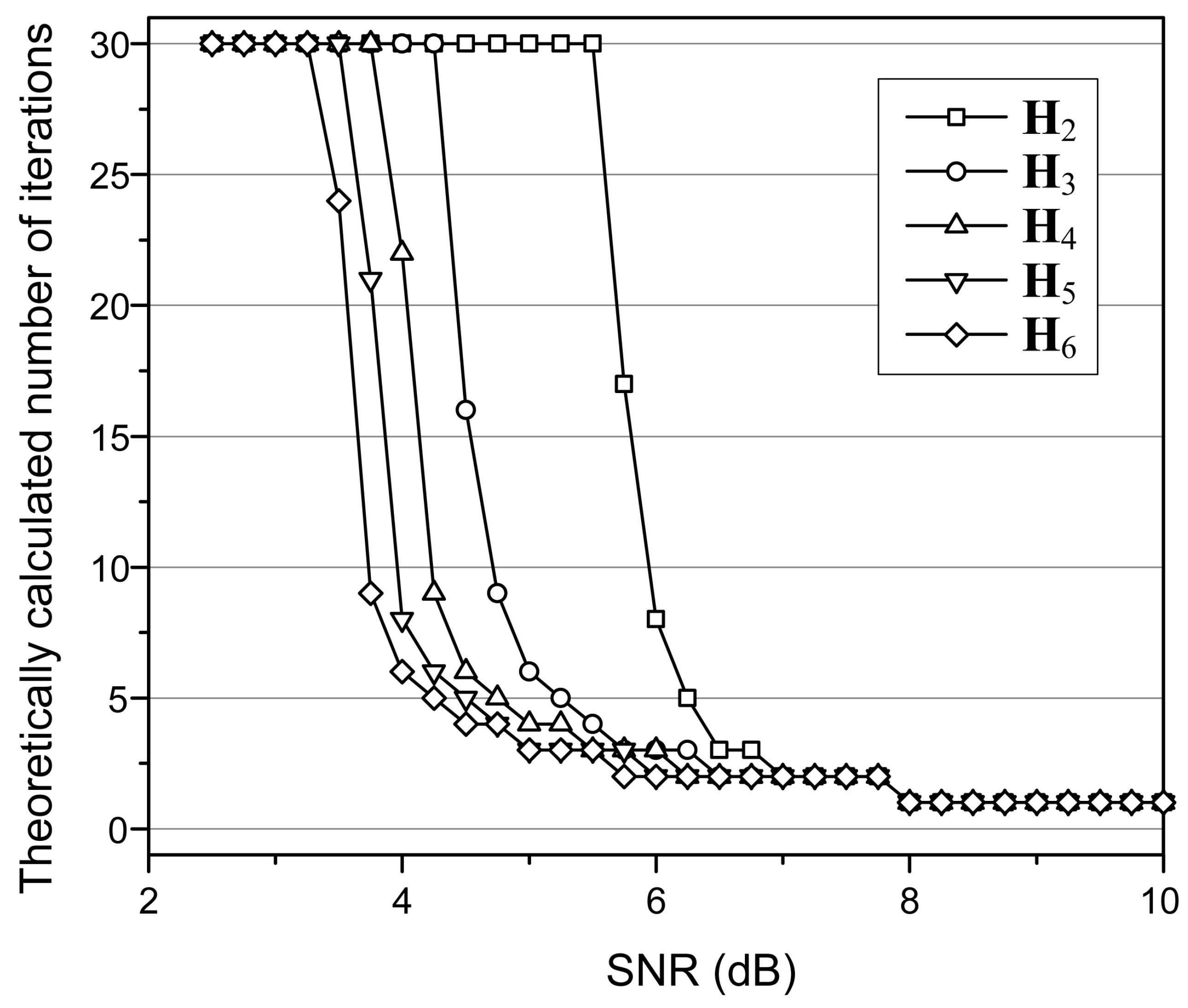
Therefore, we analyze the theoretical number of iterations needed to achieve successful decoding for a range of SNR. The numbers are depicted in Figure 6. Since the graphs look similar to the simulation results shown in Figure 2, the proposed decoding algorithm is consistent with the theoretical analysis. In addition, the existence of an initial partial H-matrix that provides the same error-correcting performance as the full H-matrix for a specific SNR is explained theoretically.
6. Hardware Architecture
A simple modification of the existing decoder hardware allows decoding of the proposed algorithm. Therefore, while maintaining the basic structure of the existing architecture, the addition of the capability to dynamically select the optimal partial H-matrix based on the channel state significantly reduces energy consumption while maintaining decoding accuracy. Through such a simple modification, the proposed decoding method can be easily integrated into existing systems, offering improved performance and energy efficiency.
6.1. Dedicated Syndrome Check Module
LDPC decoders that utilize soft-information are generally required to perform the first decoding iteration. This approach is adopted because generating the soft-information itself consumes a significant amount of latency, thus making it more advantageous in several aspects to proceed with an initial decoding iteration rather than performing a separate syndrome check. However, the proposed decoding algorithm, which also uses soft-information, requires decoding with partial H-matrices of various sizes. To accommodate this, a separate syndrome check module is incorporated. Employing an independent syndrome check module can significantly reduce decoding latency, especially in good channel conditions.
Typically, a full H-matrix is not necessary for syndrome checking to verify the integrity of a codeword; it only needs to cover the entire message. Therefore, the size of the dedicated syndrome check module can be very compact and implemented with minimal effort. Table 1 shows the gate count for syndrome check logic of LDPC codes of various sizes in 65 nm CMOS process. For a commonly used 4 KB LDPC code with a rate of 0.9, it only requires 22 k equivalent gates, which is about 1% of the total decoder area. Therefore, incorporating this logic into an existing decoder incurs minimal overhead and can be easily applied to any decoding architecture.

Table 1.
Areas of the Syndrome Checking Logic for Various Sizes of LDPC Codes in 65 nm CMOS.
| Code 1 [12] | Code 2 [18] | Code 3 | |
|---|---|---|---|
| Target system | SSD | SSD | IEEE 802.11ac |
| Code type | Array | EG-LDPC | PEG |
| Cyclic | QC | Cyclic or QC | QC |
| User-message size | 4 KB | 8 KB | 1944 bits |
| Code rate | 0.9 | 0.96 | 0.5 |
| Target frequency (MHz) | 250 | 250 | 500 |
| Area (Equation gate count) | 22.1 k | 38.4 k | 6.6 k |
6.2. Decoding Architecture
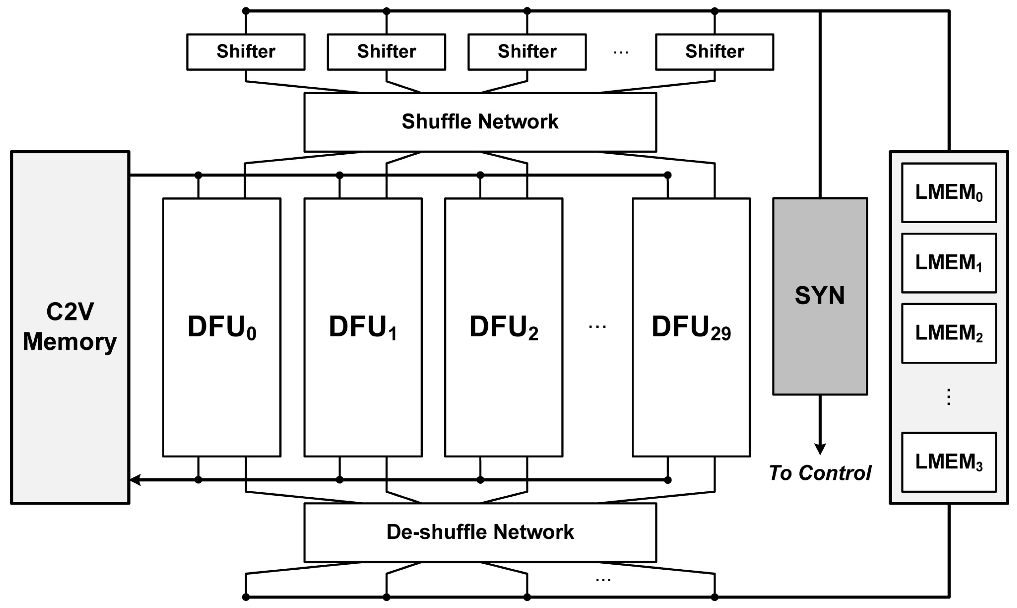
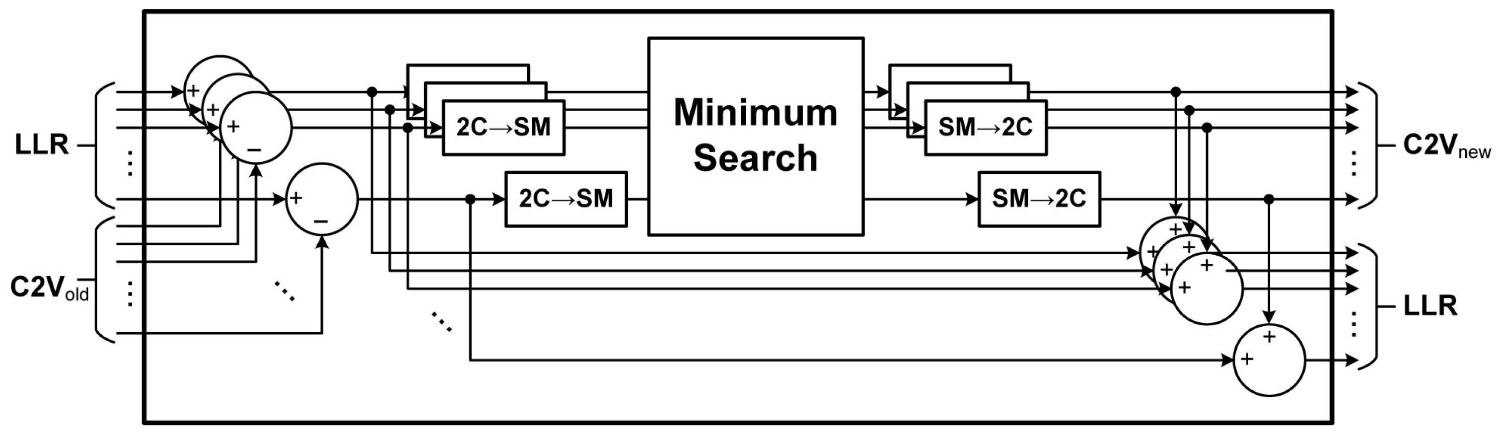
A block diagram of the proposed decoding architecture is shown in Figure 7. Except for the dedicated syndrome checking (SYN) unit, the decoding architecture is identical to the conventional layered min-sum decoder [18]. Each decoding function unit (DFU) performs the independent check node operation in parallel, and the corresponding LLR values and the intermediate C2V values are stored in LMEM and C2V memories, respectively. The detailed architecture of the DFU is shown in Figure 8. Through the shuffle network, the appropriate LLR and C2V values are obtained, followed by number system conversion, addition and subtraction operations. For a fair evaluation of the implementation, the most efficient method among the existing approaches has been applied for the Minimum search logic [19,20].
The shuffle and de-shuffle networks align the LLR and C2V values. In the conventional architecture, all syndromes are checked in each DFU operation since the conventional decoding algorithm always uses the full H-matrix. However, the proposed partial LDPC decoding uses the partial H-matrices instead of the full H-matrix when the channel is reliable. Since decoding with the partial H-matrices does not compute all check node equations and syndromes, the dedicated SYN unit, which checks remaining syndromes, is additionally applied. As a result, proposed partial LDPC decoding can be applied by adding a simple SYN unit to any existing structure with ease.
7. Implementation Results
A prototype partial LDPC decoder, designed to decode the (607, 60, 6) array LDPC code that protects 4 KB messages, is implemented in a 65 nm CMOS process. Including the dedicated SYNCHK unit, the 4 KB LDPC decoder is realized with 1018 k equivalent gates and consumes 279 mW. Table 2 compares the proposed decoder to recently reported decoders for NAND flash storage systems. For quantitative comparisons, the energy efficiency normalized to 65 nm CMOS technology is compared with assuming an operating voltage of 1 V. More precisely,
Compared to a previously reported LDPC decoder [18], the decoder adopting the proposed algorithm saves 93% of the energy consumed in decoding. The hard-decision based ECC decoders, such as concatenated-BCH (CBCH) or BCH decoders, may consume smaller amounts of energy in the decoding process; however, these are difficult to apply to recent NAND flash memories due to their weak error-correcting performance. The proposed decoder even consumes less energy than the BCH decoder in [21], which is not tightly optimized. The comparison with the implementation results shows that the proposed decoder using the proposed energy-efficient LDPC decoding algorithm has outstanding performances compared to recent implementations.
Table 2.
Comparison of Various ECC Decoders for NAND Flash Controllers.
| This Work | DASIP [22] | TVLSI [18] | ISCAS [23] | JSSC [24] | ISCAS [21] | |
|---|---|---|---|---|---|---|
| ECC type | LDPC | LDPC | LDPC | LDPC | CBCH | BCH |
| Technology | 65 nm | 45 nm | 130 nm | 45 nm | 65 nm | 45 nm |
| Code rate | 0.96 | 0.96 | 0.96 | 0.9 | 0.93 | 0.9 |
| User-message size | 4 KB | 8 KB | 8 KB | 1 KB | 8 KB | 1KB |
| Quantization level | 4 bits | 7 bits | 4 bits | 1 bit | 1 bit | 1 bit |
| Internal precision | 8 bits | 7 bits | 4 bits | N. A. a | N. A. | N. A. |
| Operating voltage (V) | 1.0 | N. A. | 1.2 | N. A. | 1.2 | 1.05 |
| Operating frequency (MHz) | 200 | 179 | 131 | 200 | 250 | 400 |
| Decoding throughput (Gb/s) | 2.96–29.6 | 0.9 | 5.4 | 3.2 | 17.7 | 6.4 |
| Area (Equation gate count) | 1018 k | N. A. | N. A. | 700 k | 335 k | 230k |
| Power consumption (mW) | 279 | N. A. | 2090 | N. A. | 48.5 b | 88.4 |
| Energy efficiency (pJ/bit) | 9.43–94.26 | N. A. | 387 | N. A. | 2.74 b | 13.8 |
| Normalized energy efficiency c (pJ/bit) | 9.43–94.26 | N. A. | 134 | N. A. | 1.9 b | 12.5 |
a Not announced; b At the raw bit-error rate of ; c Normalized energy efficiency = Energy efficiency × (65 nm/technology) × (1/Operating voltage)2. List of abbreviations: DASIP: Conference on Design and Architectures for Signal and Image Processing; TVLSI: IEEE Transactions on VLSI Systems; ISCAS: International Symposiums on Circuits and Systems; JSSC: Journal of Solid-State Circuits.
8. Conclusions
This paper has presented a new energy-efficient LDPC decoding method called partial LDPC decoding by taking into account the characteristics of the NAND flash channel. The proposed algorithm decodes by using a portion of the full H-matrix in order to save the energy consumed in the decoding. The partial decoding can provide a range of error-correcting capabilities by adjusting the size of the partial H-matrix, enabling a trade-off between energy consumption and error-correcting capabilities. The existence of a partial H-matrix, which achieves almost the same decoding performance as that of the full H-matrix for a specific SNR, has theoretically been analyzed and proved by intensive simulations. A prototype decoder to implement the proposed algorithm has been developed for 4 KB LDPC codes using a 65 nm CMOS process. The proposed decoder reduces energy consumption by 93% compared to recent LDPC decoding architectures.
Funding
This research received no external funding.
Data Availability Statement
Data are contained within the article.
Conflicts of Interest
The author declares no conflicts of interest.
Abbreviations
The following abbreviations are used in this manuscript:
| LDPC | Low-density parity-check |
| SSD | Solid-state drive |
| SD | Secure digital |
| ECC | Error correcting code |
| BCH | Bose–Chaudhuri–Hocquenghem |
| RS | Reed–Solomon |
| BP | Belief Propagation |
| QC | Quasi-cyclic |
| LLR | Log-likelihood ratio |
| SPA | Sum-product algorithm |
| MSA | Min-sum algorithm |
| MAI | Maximally allowed iterations |
| SNR | Signal-to-noise ratio |
| BER | Bit-error rate |
| AWGN | Additive white Gaussian noise |
| V2C | Variable-to-check |
| C2V | Check-to-variable |
| 2C | 2’s complement |
| SM | Signed magnitude |
| CBCH | Concatenated BCH |
| CMOS | Complementary Metal-Oxide-Semiconductor |
References
- Lee, D.; Chang, I.J.; Yoon, S.Y.; Jang, J.; Jang, D.S.; Hahn, W.G.; Park, J.Y.; Kim, D.G.; Yoon, C.; Lim, B.S.; et al. A 64Gb 533Mb/s DDR interface MLC NAND Flash in sub-20 nm technology. In Proceedings of the 2012 IEEE International Solid-State Circuits Conference, San Francisco, CA, USA, 19–23 February 2012; pp. 430–432. [Google Scholar] [CrossRef]
- Li, Y.; Lee, S.; Oowada, K.; Nguyen, H.; Nguyen, Q.; Mokhlesi, N.; Hsu, C.; Li, J.; Ramachandra, V.; Kamei, T.; et al. 128Gb 3b/cell NAND flash memory in 19 nm technology with 18 MB/s write rate and 400 Mb/s toggle mode. In Proceedings of the 2012 IEEE International Solid-State Circuits Conference, San Francisco, CA, USA, 19–23 February 2012; pp. 436–437. [Google Scholar] [CrossRef]
- Cai, Y.; Haratsch, E.F.; Mutlu, O.; Mai, K. Error patterns in MLC NAND flash memory: Measurement, characterization, and analysis. In Proceedings of the 2012 Design, Automation & Test in Europe Conference & Exhibition, Dresden, Germany, 12–16 March 2012; pp. 521–526. [Google Scholar] [CrossRef]
- Cai, Y.; Yalcin, G.; Mutlu, O.; Haratsch, E.F.; Cristal, A.; Unsal, O.S.; Mai, K. Flash correct-and-refresh: Retention-aware error management for increased flash memory lifetime. In Proceedings of the 2012 IEEE 30th International Conference on Computer Design (ICCD), Montreal, QC, Canada, 30 September–3 October 2012; pp. 94–101. [Google Scholar] [CrossRef]
- Yaakobi, E.; Ma, J.; Grupp, L.; Siegel, P.H.; Swanson, S.; Wolf, J.K. Error characterization and coding schemes for flash memories. In Proceedings of the 2010 IEEE Globecom Workshops, Miami, FL, USA, 6–10 December 2010; pp. 1856–1860. [Google Scholar] [CrossRef]
- Hwang, S.; Jung, J.; Kim, D.; Ha, J.; Park, I.C.; Lee, Y. An energy-optimized (37840, 34320) symmetric BC-BCH decoder for healthy mobile storages. In Proceedings of the 2017 IEEE Asian Solid-State Circuits Conference (A-SSCC), Seoul, Republic of Korea, 6–8 November 2017; pp. 169–172. [Google Scholar] [CrossRef]
- Hwang, S.; Moon, S.; Jung, J.; Kim, D.; Park, I.C.; Ha, J.; Lee, Y. Energy-Efficient Symmetric BC-BCH Decoder Architecture for Mobile Storages. IEEE Trans. Circuits Syst. Regul. Pap. 2019, 66, 4462–4475. [Google Scholar] [CrossRef]
- Gunnam, K.; Choi, G.; Wang, W.; Yeary, M. Multi-Rate Layered Decoder Architecture for Block LDPC Codes of the IEEE 802.11n Wireless Standard. In Proceedings of the 2007 IEEE International Symposium on Circuits and Systems (ISCAS), New Orleans, LA, USA, 27–30 May 2007; pp. 1645–1648. [Google Scholar] [CrossRef]
- Kienle, F.; Brack, T.; Wehn, N. A synthesizable IP core for DVB-S2 LDPC code decoding. In Proceedings of the Design, Automation and Test in Europe, Munich, Germany, 7–11 March 2005; Volume 3, pp. 100–105. [Google Scholar] [CrossRef]
- Chen, J.; Dholakia, A.; Eleftheriou, E.; Fossorier, M.; Hu, X.Y. Near optimal reduced-complexity decoding algorithms for LDPC codes. In Proceedings of the Proceedings IEEE International Symposium on Information Theory, Lausanne, Switzerland, 30 June–5 July 2002; p. 455. [Google Scholar] [CrossRef]
- Mohsenin, T.; Truong, D.N.; Baas, B.M. A Low-Complexity Message-Passing Algorithm for Reduced Routing Congestion in LDPC Decoders. IEEE Trans. Circuits Syst. Regul. Pap. 2010, 57, 1048–1061. [Google Scholar] [CrossRef]
- Olcer, S. Decoder architecture for array-code-based LDPC codes. In Proceedings of the GLOBECOM ’03. IEEE Global Telecommunications Conference (IEEE Cat. No.03CH37489), San Francisco, CA, USA, 1–5 December 2003; Volume 4, pp. 2046–2050. [Google Scholar] [CrossRef]
- Studer, C.; Preyss, N.; Roth, C.; Burg, A. Configurable high-throughput decoder architecture for quasi-cyclic LDPC codes. In Proceedings of the 2008 42nd Asilomar Conference on Signals, Systems and Computers, Pacific Grove, CA, USA, 26–29 October 2008; pp. 1137–1142. [Google Scholar] [CrossRef]
- Kienle, F.; Wehn, N. Low complexity stopping criterion for LDPC code decoders. In Proceedings of the 2005 IEEE 61st Vehicular Technology Conference, Stockholm, Sweden, 30 May–1 June 2005; Volume 1, pp. 606–609. [Google Scholar] [CrossRef]
- Chen, Y.; Hocevar, D. A FPGA and ASIC implementation of rate 1/2, 8088-b irregular low density parity check decoder. In Proceedings of the GLOBECOM ’03. IEEE Global Telecommunications Conference (IEEE Cat. No.03CH37489), San Francisco, CA, USA, 1–5 December 2003; Volume 1, pp. 113–117. [Google Scholar] [CrossRef]
- Moon, T.K. Error Correction Coding: Mathematical Methods and Algorithms, 1st ed.; Wiley-Interscience: Hoboken, NJ, USA, 2005. [Google Scholar]
- Chung, S.Y.; Richardson, T.; Urbanke, R. Analysis of sum-product decoding of low-density parity-check codes using a Gaussian approximation. IEEE Trans. Inf. Theory 2001, 47, 657–670. [Google Scholar] [CrossRef]
- Kim, J.; Sung, W. Rate-0.96 LDPC Decoding VLSI for Soft-Decision Error Correction of NAND Flash Memory. IEEE Trans. Very Large Scale Integr. (VLSI) Syst. 2014, 22, 1004–1015. [Google Scholar] [CrossRef]
- Lee, Y.; Kim, B.; Jung, J.; Park, I.C. Low-Complexity Tree Architecture for Finding the First Two Minima. IEEE Trans. Circuits Syst. II Express Briefs 2015, 62, 61–64. [Google Scholar] [CrossRef]
- Jung, J.; Lee, Y.; Park, I.C. Area-efficient method to approximate two minima for LDPC decoders. Electron. Lett. 2014, 50, 1701–1702. [Google Scholar] [CrossRef]
- Lee, K.; Lim, S.; Kim, J. Low-cost, low-power and high-throughput BCH decoder for NAND Flash Memory. In Proceedings of the 2012 IEEE International Symposium on Circuits and Systems (ISCAS), Seoul, Republic of Korea, 20–23 May 2012; pp. 413–415. [Google Scholar] [CrossRef]
- Zaidi, S.A.A.; Awais, M.; Condo, C.; Martina, M.; Masera, G. FPGA accelerator of Quasi cyclic EG-LDPC codes decoder for NAND flash memories. In Proceedings of the 2013 Conference on Design and Architectures for Signal and Image Processing, Cagliari, Italy, 8–10 October 2013; pp. 190–195. [Google Scholar]
- Kim, D.; Chung, B.; Kim, R.E. Improved hard-decision decoding LDPC Codec IP design. In Proceedings of the 2012 IEEE International Symposium on Circuits and Systems (ISCAS), Seoul, Republic of Korea, 20–23 May 2012; pp. 416–419. [Google Scholar] [CrossRef]
- Lee, Y.; Yoo, H.; Jung, J.; Jo, J.; Park, I.C. A 2.74-pJ/bit, 17.7-Gb/s Iterative Concatenated-BCH Decoder in 65-nm CMOS for NAND Flash Memory. IEEE J. Solid State Circuits 2013, 48, 2531–2540. [Google Scholar] [CrossRef]
Figure 1.
Uncorrected BER performances of various partial H-matrices obtained from a (149, 61, 6) array LDPC code.
Figure 1.
Uncorrected BER performances of various partial H-matrices obtained from a (149, 61, 6) array LDPC code.

Figure 2.
The average number of iterations simulated for various partial H-matrices of the (149, 61, 6) array LDPC code.
Figure 2.
The average number of iterations simulated for various partial H-matrices of the (149, 61, 6) array LDPC code.

Figure 3.
The comparison of memory accesses resulting from the conventional and proposed decoding algorithms for the (149, 61, 6) array LDPC code.
Figure 3.
The comparison of memory accesses resulting from the conventional and proposed decoding algorithms for the (149, 61, 6) array LDPC code.

Figure 4.
The decoding latency of the proposed algorithm normalized by that of the conventional one for the (149, 61, 6) array LDPC code.
Figure 4.
The decoding latency of the proposed algorithm normalized by that of the conventional one for the (149, 61, 6) array LDPC code.

Figure 5.
The probability distribution of LLR values and the estimated BERs of the (149, 61, 6) array LDPC code when the SNR is 5 dB.
Figure 5.
The probability distribution of LLR values and the estimated BERs of the (149, 61, 6) array LDPC code when the SNR is 5 dB.

Figure 6.
The theoretically calculated number of iterations for the various partial H-matrices of the (149, 61, 6) array LDPC code.
Figure 6.
The theoretically calculated number of iterations for the various partial H-matrices of the (149, 61, 6) array LDPC code.

Figure 7.
The prototype decoder for the proposed energy-efficient partial LDPC decoding algorithm for the (607, 60, 6) array LDPC code.
Figure 7.
The prototype decoder for the proposed energy-efficient partial LDPC decoding algorithm for the (607, 60, 6) array LDPC code.

Figure 8.
The detailed architecture of the decoding function unit.

Disclaimer/Publisher’s Note: The statements, opinions and data contained in all publications are solely those of the individual author(s) and contributor(s) and not of MDPI and/or the editor(s). MDPI and/or the editor(s) disclaim responsibility for any injury to people or property resulting from any ideas, methods, instructions or products referred to in the content. |
© 2024 by the author. Licensee MDPI, Basel, Switzerland. This article is an open access article distributed under the terms and conditions of the Creative Commons Attribution (CC BY) license (https://creativecommons.org/licenses/by/4.0/).
Share and Cite
MDPI and ACS Style
Jung, J. Energy-Efficient Partial LDPC Decoding for NAND Flash-Based Storage Systems. Electronics 2024, 13, 1392. https://doi.org/10.3390/electronics13071392
AMA Style
Jung J. Energy-Efficient Partial LDPC Decoding for NAND Flash-Based Storage Systems. Electronics. 2024; 13(7):1392. https://doi.org/10.3390/electronics13071392
Chicago/Turabian StyleJung, Jaehwan. 2024. "Energy-Efficient Partial LDPC Decoding for NAND Flash-Based Storage Systems" Electronics 13, no. 7: 1392. https://doi.org/10.3390/electronics13071392
Note that from the first issue of 2016, this journal uses article numbers instead of page numbers. See further details here.