Three-Dimensional Ray-Tracing-Based Propagation Prediction Model for Macrocellular Environment at Sub-6 GHz Frequencies
Abstract
:1. Introduction
- More detailed environmental structures are considered, including not only building elements (e.g., internal yards, indentations, edges, and roof structures), terrain profiles, green belts, etc., but also different terrain features.
- Considering the physical laws associated with wave propagation in urban environments and the determination efficiency of the multipath components (rays) between the Tx and Rx, the path classification technology is adopted.
- In order to improve the efficiency of coverage prediction over large areas, a hybrid propagation model based on the statistical model-assisted RT algorithm is established.
2. Macrocellular Environment Representation
2.1. Buildings
- (1)
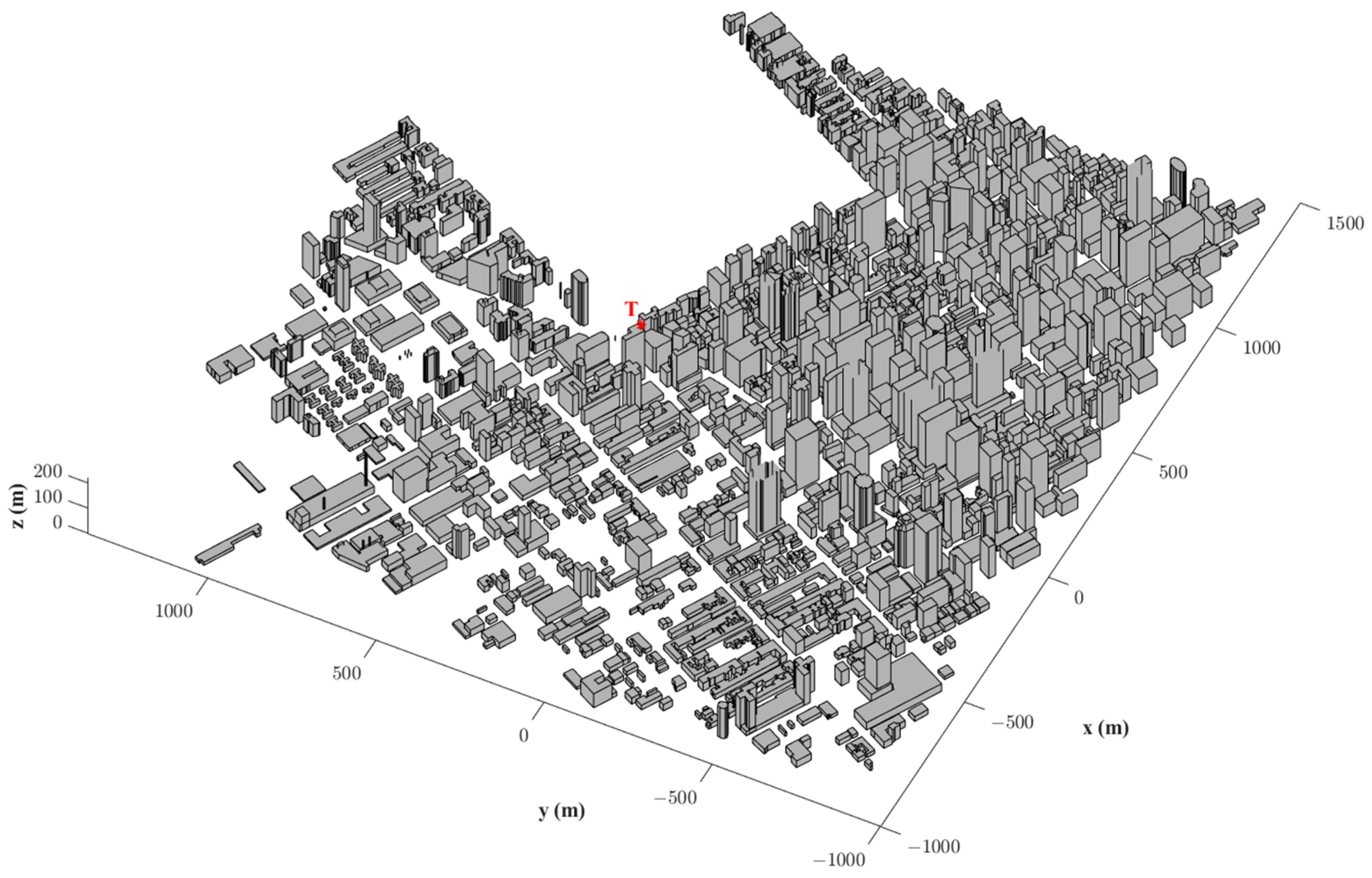
- Building groups are divided into different blocks, and each building presents a uniform height (i.e., polygonal cylinder). The building’s height is either relative to the ground or absolutely above sea level. Additionally, flat rooftops are used (horizontal planes). In urban databases, the basic element is a polygonal cylinder, which is constructed with many planar objects. The lateral face and vertical edge of the polygonal cylinder represent the wall and corner, respectively.
- (2)
- Each building in the macrocell is simplified as a combination of horizontal and vertical faces. Hence, important information regarding faces, wedges, and apexes can be easily extracted for tracing rays. On the basis of this extracted information, radio propagation in the studied environment can be simplified into direct rays and all possible combinations of reflected and diffracted rays reaching the Rx.
- (3)
- A high inner building is called a tower, and a low one is called a courtyard. A tower or courtyard, such as the building, is modeled as a polygonal cylinder.
2.2. Green Belts
2.3. Terrain Profile and Terrain Features
3. 3D RT Model
3.1. Simulation Setup
- (1)
- Tx parameters, namely, transmitted power, carrier frequency, antenna gain, antenna polarization, radiation pattern, and position, are established.
- (2)
- Rx parameters, namely, antenna gain, antenna polarization, and radiation pattern, are also set.
- (3)
- Prediction functions, such as path loss, received power, and all the information of propagation paths from the Tx to Rx (including 3D RT trajectory, time of arrival, angle of arrival, angle of departure, and field strength), are established.
- (4)
- The simulation prediction method should be selected and divided into three types: (a) disperse-point prediction (Rxs are placed at arbitrary locations); (b) single-route prediction, i.e., Rxs are placed along the test route with fixed intervals; and (c) coverage prediction, i.e., Rxs are uniformly distributed in the area of interest with uniform height.
3.2. Loading and Preprocessing of Environmental Information
- (1)
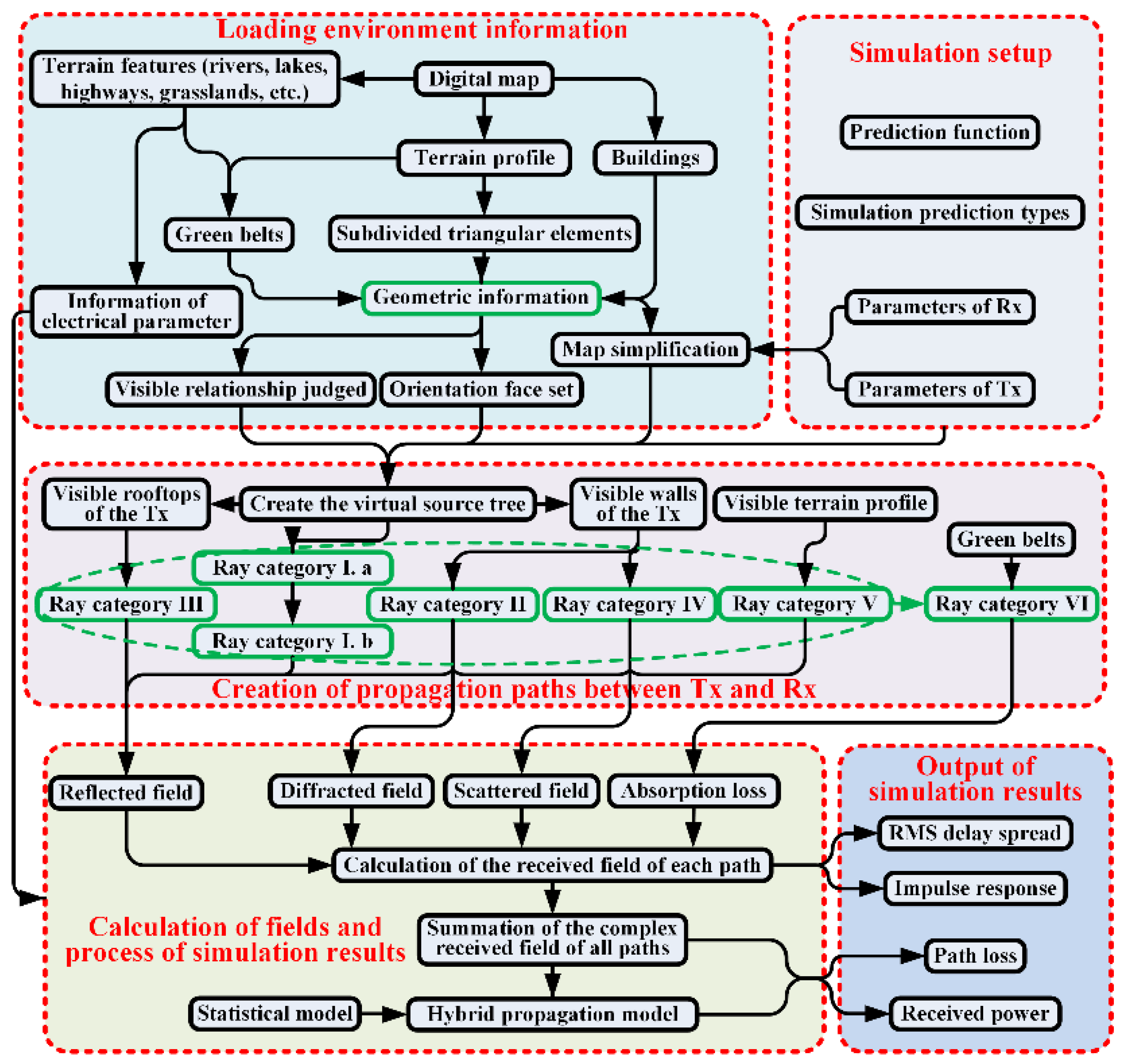
- Environmental information includes electrical parameters (relative permittivity and conductivity) and geometric information (including buildings, green belts, terrain profile, and terrain features) and is obtained from the digital map.
- (2)
- According to the Tx and Rx positions, geometrical factors, which exert little or no effect on prediction results, are neglected from the digital map using a preprocessing technique for the geometric information of buildings. This preprocessing technique can retain the geometric information of buildings that create low-order reflected or diffracted rays between transmitting and receiving antennas. In the area containing these buildings, the rays carrying strong energy can arrive. Therefore, if the area is confirmed before executing the RT program, some repeated judgments could be avoided.
- (3)
- The visible relationship between vertical walls and simulated points (Rxs) should be assessed and stored. To determine the relationship, a simulated point can be treated as a light source. When a vertical wall is illuminated by a point, the relationship between the vertical wall and the simulated point is called “visible”. In this condition, the reflected ray on the vertical wall may arrive at this simulated point.
- (4)
- The orientation face set (already present in [21] for 2D conditions) between vertical walls should also be determined and stored in 3D conditions to accelerate the calculation of the reflection. The plane on which the wall of the building exists divides the 3D space into two half-spaces, and the half-space pointed by the outward normal vector of the vertical wall is described as the valid region of the vertical wall. If any vertex of a vertical rectangular wall is located in the valid region of the reflected wall, and at the same time, if any vertex of this reflected rectangular wall is located in the valid region of the vertical wall, the wall is defined as the orientation face of the reflected wall. Thus, all the orientation faces of the reflected wall comprise its orientation face set.
3.3. Creation of Propagation Paths between the Tx and Rx
- Ray category I. Category I can also be divided into two fine types. For the first type (called ray category I. a), the following ray paths are considered: direct rays as line of sight (LOS), ray paths with an arbitrary number of reflections on vertical walls, ray paths with an arbitrary number of diffractions on vertical edges (corners), and all combinations of reflections on vertical walls and diffractions on vertical edges. For the other type (called ray category I. b), all ray paths mentioned above are included, including one additional reflection on the ground.
- Ray category II. Category II accounts only for single-diffracted ray paths on horizontal eaves belonging to the roofs of buildings.
- Ray category III. Category III accounts only for single-reflected ray paths on horizontal roofs of buildings.
- Ray category IV. Category IV includes only single-diffuse-scattering ray paths on vertical walls of buildings.
- Ray category V. Category V includes reflections on large undulating terrain. When considering such paths, the ground cannot be considered flat. Paths belonging to ray category I. b should be ignored to avoid repetition of reflections on the ground.
- Ray category VI. This category involves the five ray categories mentioned above and additional multiple transmissions through the green belt.
3.4. Calculation of Fields and Process of Simulation Results
3.5. Output of Simulation Results
4. Measurement and Verification
4.1. Outdoor Scenario 1
4.2. Outdoor Scenario 2
5. Power Coverage Predictions
6. Conclusions
Author Contributions
Funding
Data Availability Statement
Conflicts of Interest
References
- Kim, K.; Oh, S. Geometric Optics-based Propagation Prediction Model in Urban Street Canyon Environments. IEEE Antennas Wirel. Propag. Lett. 2016, 15, 1128–1131. [Google Scholar] [CrossRef]
- Kocevska, T.; Javornik, T.; Švigelj, A.; Rashkovska, A.; Hrovat, A. Identification of Indoor Radio Environment Properties from Channel Impulse Response with Machine Learning Models. Electronics 2023, 12, 2746. [Google Scholar] [CrossRef]
- Seretis, A.; Sarris, C.D. An Overview of Machine Learning Techniques for Radiowave Propagation Modeling. IEEE Trans. Antennas Propag. 2022, 70, 3970–3985. [Google Scholar] [CrossRef]
- Kishore, S.; Greenstein, L.J.; Poor, H.V.; Schwartz, S.C. Uplink User Capacity in a CDMA Macrocell with a Hotspot Microcell: Exact and Approximate Analyses. IEEE Trans. Wirel. Commun. 2003, 2, 364–374. [Google Scholar] [CrossRef]
- Choi, M.S.; Park, H.K.; Heo, Y.H.; Oh, S.H.; Myung, N.H. A 3-D Propagation Model Considering Building Transmission Loss for Indoor Wireless Communications. ETRI J. 2014, 28, 247–249. [Google Scholar] [CrossRef]
- Kalliola, K.; Laitinen, H.; Vainikainen, P.; Toeltsch, M.; Laurila, J.; Bonek, E. 3-D Double-directional Radio Channel Characterization for Urban Macrocellular Applications. IEEE Trans. Antennas Propag. 2003, 51, 3122–3133. [Google Scholar] [CrossRef]
- Sangodoyin, S.; Kristem, V.; Umit Bas, C.; Käske, M.; Lee, J.; Schneider, C.; Sommerkorn, G.; Zhang, C.J.; Thomä, R.; Molisch, A.F. Cluster Characterization of 3-D MIMO Propagation Channel in an Urban Macrocellular Environment. IEEE Trans. Wirel. Commun. 2018, 17, 5076–5091. [Google Scholar] [CrossRef]
- Fan, W.; Carton, I.; Kyösti, P.; Pedersen, G.F. Emulating Ray-tracing Channels in Multiprobe Anechoic Chamber Setups for Virtual Drive Testing. IEEE Trans. Antennas Propag. 2016, 64, 730–739. [Google Scholar] [CrossRef]
- Puggelli, F.; Carluccio, G.; Albani, M. A Novel Ray Tracing Algorithm for Scenarios Comprising Pre-ordered Multiple Planar Reflectors, Straight Wedges, and Vertexes. IEEE Trans. Antennas Propag. 2014, 62, 4336–4341. [Google Scholar] [CrossRef]
- Liang, G.; Bertoni, H.L. A New Approach to 3-D Ray Tracing for Propagation Prediction in Cities. IEEE Trans. Antennas Propag. 1998, 46, 853–863. [Google Scholar] [CrossRef]
- Schettino, D.N.; Moreira, F.J.S.; Rego, C.G. Efficient Ray Tracing for Radio Channel Characterization of Urban Scenarios. IEEE Trans. Magn. 2007, 43, 1305–1308. [Google Scholar] [CrossRef]
- Franceshetti, G.; Iodice, A.; Riccio, D. Radio Propagation in the Urban Scenario, 1st ed.; Artech: Boston, MA, USA, 2023; pp. 190–195. [Google Scholar]
- Iskander, M.F.; Yun, Z. Propagation Prediction Models for Wireless Communication Systems. IEEE Trans. Microw. Theory Techn. 2002, 50, 662–673. [Google Scholar] [CrossRef]
- Mellios, E.; Nix, A.R.; Hilton, G.S. Ray-tracing Urban Macrocell Propagation Statistics and Comparison with WINNER II/+ Measurements and Models. In Proceedings of the 2012 Loughborough Antennas & Propagation Conference (LAPC), Loughborough, UK, 12–13 November 2012. [Google Scholar]
- Atamanesh, M.; Farzaneh, F. Microwave Wireless Orthogonal Frequency Division Multiplexing System Optimum Guard Interval Evaluation in an Urban Scenario Around 5 GHz. IET Commun. 2011, 5, 1113–1122. [Google Scholar] [CrossRef]
- Leonor, N.R.; Faria, S.; Ramos, G.; Castellanos, P.V.G.; Rodríguez, C.; da Silva Mello, L.; Caldeirinha, R.F.S. Site-Specific Radio Propagation Model for Macrocell Coverage at Sub-6 GHz Frequencies. IEEE Trans. Antennas Propag. 2022, 70, 9706–9715. [Google Scholar] [CrossRef]
- Gómez, J.; Hellín, C.J.; Valledor, A.; Barranquero, M.; Cuadrado-Gallego, J.J.; Tayebi, A. Design and Implementation of an Innovative High-performance Radio Propagation Sim-ulation Tool. IEEE Access. 2023, 11, 94069–94080. [Google Scholar] [CrossRef]
- Liu, H.T.; Li, B.H.; Qi, D.S. Novel Geometrical Database Model for Line-based GIS Urban Maps in 2D/2.5D Ray-tracing Algorithms. Microw. Opt. Technol. Lett. 2004, 43, 307–310. [Google Scholar] [CrossRef]
- OpenStreetMap. Available online: https://www.openstreetmap.org (accessed on 23 June 2021).
- Liu, Z.Y.; Guo, L.X.; Guan, X.W. Accelerated Ray Tracing Algorithm under Urban Macro Cell. In Proceedings of the SPIE Remote Sensing, Toulouse, France, 21–24 September 2015. [Google Scholar]
- Liu, Z.Y.; Guo, L.X.; Fan, T.Q. Microcellular Propagation Prediction Model Based on an Improved Ray Tracing Algorithm. J. Opt. Soc. Am. A 2013, 30, 2372–2380. [Google Scholar] [CrossRef] [PubMed]
- Aguado Agelet, F.; Formella, A.; Hernando Rabanos, J.M.; Isasi de Vicente, F.; Perez Fontan, F. Efficient Ray-tracing Acceleration Techniques for Radio Propagation Modeling. IEEE Trans. Veh. Technol. 2000, 49, 2089–2104. [Google Scholar] [CrossRef]
- El-Sallabi, H.M.; Vainikainen, P. Improvements to Diffraction Coefficient for Non-perfectly Conducting Wedges. IEEE Trans. Antennas Propag. 2005, 53, 3105–3109. [Google Scholar] [CrossRef]
- Sarkar, T.K.; Ji, Z.; Kim, K.; Medouri, A.; Salazar-Palma, M. A Survey of Various Propagation Models for Mobile Communication. IEEE Antennas Propag. Mag. 2003, 45, 51–82. [Google Scholar] [CrossRef]
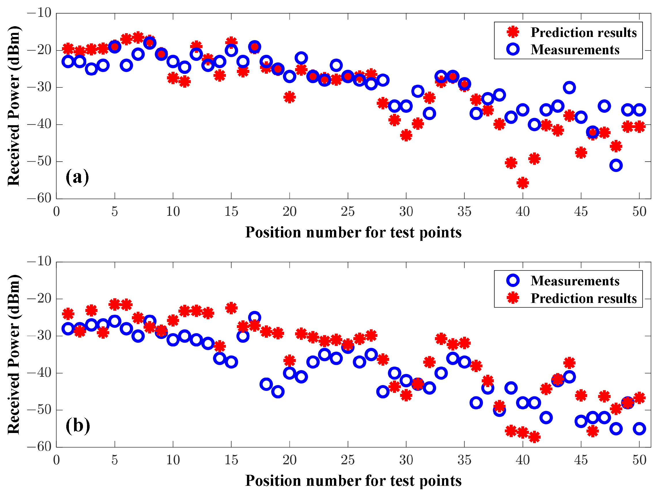


| Frequency | Mean | Standard Deviation |
|---|---|---|
| 610 MHz | −2.074 dBm | 5.114 dBm |
| 990 MHz | 3.667 dBm | 5.598 dBm |
| Propagation Model | Mean | Standard Deviation |
|---|---|---|
| Proposed RT | 0.22 dBm | 6.49 dBm |
| Classical RT | 0.46 dBm | 8.62 dBm |
Disclaimer/Publisher’s Note: The statements, opinions and data contained in all publications are solely those of the individual author(s) and contributor(s) and not of MDPI and/or the editor(s). MDPI and/or the editor(s) disclaim responsibility for any injury to people or property resulting from any ideas, methods, instructions or products referred to in the content. |
© 2024 by the authors. Licensee MDPI, Basel, Switzerland. This article is an open access article distributed under the terms and conditions of the Creative Commons Attribution (CC BY) license (https://creativecommons.org/licenses/by/4.0/).
Share and Cite
Liu, Z.; Zhao, P.; Guo, L.; Nan, Z.; Zhong, Z.; Li, J. Three-Dimensional Ray-Tracing-Based Propagation Prediction Model for Macrocellular Environment at Sub-6 GHz Frequencies. Electronics 2024, 13, 1451. https://doi.org/10.3390/electronics13081451
Liu Z, Zhao P, Guo L, Nan Z, Zhong Z, Li J. Three-Dimensional Ray-Tracing-Based Propagation Prediction Model for Macrocellular Environment at Sub-6 GHz Frequencies. Electronics. 2024; 13(8):1451. https://doi.org/10.3390/electronics13081451
Chicago/Turabian StyleLiu, Zhongyu, Pengcheng Zhao, Lixin Guo, Zuoyong Nan, Zhigang Zhong, and Jiangting Li. 2024. "Three-Dimensional Ray-Tracing-Based Propagation Prediction Model for Macrocellular Environment at Sub-6 GHz Frequencies" Electronics 13, no. 8: 1451. https://doi.org/10.3390/electronics13081451
APA StyleLiu, Z., Zhao, P., Guo, L., Nan, Z., Zhong, Z., & Li, J. (2024). Three-Dimensional Ray-Tracing-Based Propagation Prediction Model for Macrocellular Environment at Sub-6 GHz Frequencies. Electronics, 13(8), 1451. https://doi.org/10.3390/electronics13081451


