Article

A Novel Active Anti-Disturbance Control Strategy for Unmanned Aerial Manipulator Based on Variable Coupling Disturbance Compensation

1
Research Institute of Intelligent Control and Systems, School of Astronautics, Harbin Institute of Technology, Harbin 150001, China
2
National Key Laboratory of Complex System Control and Intelligent Agent Cooperation, Harbin Institute of Technology, Harbin 150001, China
3
Ningbo Institute of Intelligent Equipment Technology Co., Ltd., Ningbo 315201, China
*
Author to whom correspondence should be addressed.
Electronics 2024, 13(8), 1477; https://doi.org/10.3390/electronics13081477
Submission received: 24 March 2024 / Revised: 9 April 2024 / Accepted: 11 April 2024 / Published: 13 April 2024

Abstract

:
Inspired by the kangaroo’s active tail wagging to stabilize its body posture while jumping, this paper proposes an active anti-disturbance control strategy for unmanned aerial manipulators based on variable coupling disturbance compensation ( AADC VCD ), which can achieve the active and energy-saving anti-disturbance performance of “using the enemy’s strength against the enemy” to keep the UAM stable under disturbances. First, the goal of using the coupling disturbance generated by the active swing of the manipulator as a control input signal for active anti-disturbance is clarified. Then, based on the proposed variable coupling disturbance model, this goal is formulated as a nonlinear programming optimization problem under specific physical constraints and solved. Finally, the coupling disturbance torque generated when the manipulator executes an active swing to the solved desired joint angles can be used to compensate and suppress other disturbances of the UAM, thereby achieving active anti-disturbance. The effectiveness and superiority of the proposed AADC VCD were validated through two simulations in Simscape. The simulation results demonstrated that our approach achieved a good active anti-disturbance and energy-saving performance, significantly reducing the position offset of the UAM caused by disturbances and improving the UAM’s ability to maintain stability.

1. Introduction

An unmanned aerial manipulator (UAM), typically comprising an unmanned aerial vehicle (UAV) and a n-degree of freedom (DOF) manipulator, allows UAVs to physically interact with the environment and carry out aerial works, making it a current research hotspot [1,2,3,4]. UAMs often work in intricate environments, subject to multi-source disturbances [5]. These disturbances affecting UAMs can be classified into two main types: coupling disturbance and lumped disturbances. The former arises from the interaction of different components within the UAM system, while the latter stem from uncertainties, unmodeled dynamics, and external disturbances [6]. Improving the anti-disturbance control performance of UAMs under these disturbances is crucial for maintaining stability and flight safety.
The movement of the manipulator coupled with the load on the end-effector can alter the center of mass (CoM) and moment of inertia (MoI) of UAMs and generate strong coupling disturbances, which are a big challenge for the stable flight of UAMs [7,8]. Current research on compensation and suppression of coupling disturbance mainly focuses on the oscillations between feedforward and feedback compensation [9,10]. For instance, force sensors have been used to directly measure the coupled disturbance and perform direct feedforward compensation [11]. In [7,12,13], the authors established a coupling disturbance model by considering the center of mass offset and carrying out feedforward compensation. In [14,15,16], disturbance estimation methods such as adaptive neural networks and an extended state observer were designed to estimate and feedback compensate coupling disturbances. While these studies achieved good results in coupling disturbance compensation and suppression, none of them considered the perspective that the coupling disturbance is exploitable. With the development of certain fault-tolerant control research in recent years, this lack has been made up for. In [17,18,19], the authors achieved a fail-safe flight solution under motor failure by analyzing and utilizing the coupling disturbance torque exerted by the manipulator on the UAV. However, these coupling disturbance utilization schemes under extreme fault conditions are not applicable for regular UAM flights.
An UAM is subjected to various lumped disturbances in the actual aerial work environment, arising from factors including wind gusts, unmodeled dynamics, and other external factors [20]. To provide UAMs with robustness against these disturbances, existing methods basically rely on various advanced controllers combined with various online disturbance-estimation-based approaches to estimate and compensate for the lumped disturbances [6,21,22,23,24]. For example, an adaptive sliding-mode disturbance observer-based finite-time control scheme [6], compliant control strategy with FIR-based disturbance observer [21], and an adaptive NN backstepping control method [9] were proposed to estimate and compensate for this effect.
Although various methods for compensation and suppression of coupling disturbance and lumped disturbances have been proposed, as mentioned above, there is a common feature among them. The final execution of these methods uses the aerodynamic force generated by the propellers to suppress these disturbances, and they do not take full advantage of the active advantages of the UAM’s manipulator. There are many animals in nature that fully exploit the advantages of their own limbs [25], and their behaviors can give unique inspiration to our research [26]. Kangaroos are well known jumping animals with hind limbs and are good at using their strong tails for active swinging to maintain balance during jumping, as shown in Figure 1 below.
Inspired by the kangaroo’s active tail wagging to stabilize its body posture while jumping, this paper proposes an active anti-disturbance control strategy based on variable coupling disturbance compensation AADC VCD for UAMs, which can achieve an active and energy-saving anti-disturbance performance and keep the UAM stable under disturbances. First, we set the goal of using the coupling disturbance generated by the active swing of the UAM’s own manipulator arm as the control input signal for active disturbance rejection. Subsequently, utilizing the proposed variable coupling disturbance model, we formulated the objective of active disturbance rejection as a nonlinear programming optimization problem [28] under specific physical constraints. Solving this optimization problem could obtain the desired joint angles of the manipulator for the active swing. Finally, the coupling disturbance torque, which is directly generated when the manipulator actively swings to the desired joint angles, could be used to compensate and suppress the impact of other disturbances on the UAM, thereby achieving active and energy-saving anti-disturbance control effects.
The salient contribution of this work is to provide a new active anti-disturbance implementation mechanism for UAMs, namely AADC VCD . This kind of active anti-disturbance strategy of “using the enemy’s strength against the enemy” has the following advantages:
  • The active advantage of using the UAM’s own manipulator can reduce energy consumption, increase UAM endurance time, and further improve the capability and limit of resisting external lumped disturbances torque. The variable load on the end-effector also contributes to this improvement.
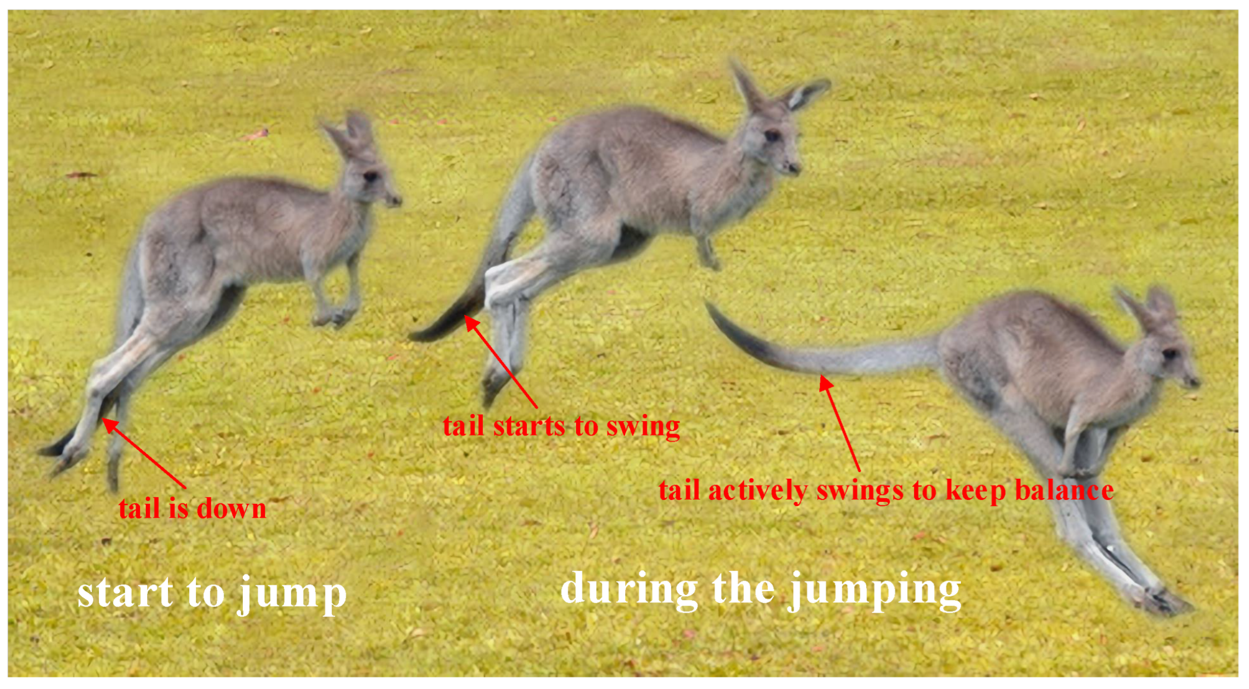
  • The coupling disturbance torque generated by the active swing of the manipulator can be faster and more direct than the aerodynamic torque generated by the propellers, because the latter can be affected by a slow aerodynamic response and slow motor response.
  • The proposed AADC VCD can also be used to achieve posture balance in highly dynamic scenarios and provide the required tilting torque for UAMs and UAVs to perform quick attitude maneuvers, such as maintaining stability at the moment when a heavy object falls in an UAM pick and place scenario.
The remainder of this paper is structured as follows: In Section 2, a dynamics model of UAMs, variable coupling disturbance model, and problem statement are described. After presenting the details of the proposed AADC VCD in Section 3, we validate it through two simulations in Simscape in Section 4, namely keeping stable in a pick and place scenario and suppressing lumped disturbance using AADC VCD . Finally, Section 5 concludes this paper and discusses potential avenues for future research.

2. Dynamics Modeling and Problem Statement

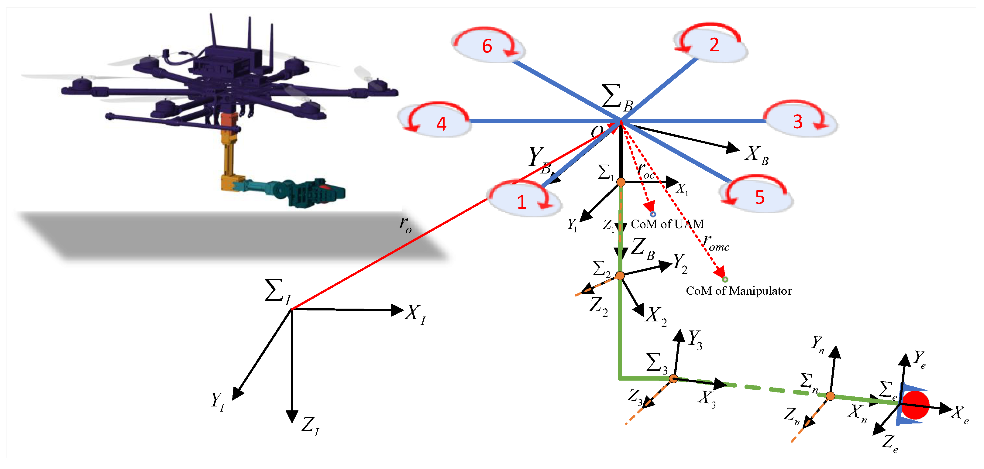
2.1. UAM Dynamics Modeling

In this paper, the considered UAM comprised a UAV base and a n-DOF manipulator. Let Σ B and Σ I denote the body-fixed coordinate system and the inertial coordinate system (NED), respectively. The former has its X B -axis aligned with the UAV’s head direction, with the Z B -axis pointing towards the ground, while the original point o of the coordinate system is situated at the UAV’s center of mass. Figure 2 illustrates the established coordinate system for the UAM. Σ i ( i = 1 , 2 , n ) represent each link’s coordinate system within the manipulator, which are formulated based on a modified DH parameter method [29].
According to reference [7], the dynamics model of UAMs can be articulated under the influence of both coupling disturbances and lumped disturbances. This formulation is presented as follows:
p ˙ b = v b v ˙ b = F l m s   I R B e 3 + g e 3 Φ ˙ b = T ( Φ b )   B ω b   B ω ˙ b = I b 1 ( τ   B ω b × ( I b   B ω b ) +   B τ c d + τ l u m )
where p b = [ x , y , z ] T and v b = [ x ˙ , y ˙ , z ˙ ] T denote the position vector and velocity vector of the UAV in Σ I . m s represents the total mass of the UAM, which encompasses both the mass of the UAV m b and that of the manipulator m m a n . F l and τ represent the lift force and the combined torque vector generated by the propellers of the UAV. g is the gravity acceleration.   I R B represents the rotation matrix from Σ B to Σ I . e 3 = [ 0 , 0 , 1 ] T .   B τ c d represents the actual coupling disturbance torque exerted on the UAM. τ l u m denotes the lumped disturbances torque caused by uncertainties, unmodeled dynamics, or external disturbances. Φ b = [ ϕ , θ , ψ ] T denote the attitude angle of roll, pitch, and yaw.   B ω b = [ p , q , r ] T denotes the angle velocity vector of the UAV. T ( Φ b ) signifies the rotation matrix that converts body angular velocity into attitude angular velocity. I b refers to the moment of inertia matrix of the UAV.
The motion of the manipulator, coupled with the changes in the load on the end-effector cause the center of mass (CoM)   B r o c and moment of inertia (MoI)   B I m a n o of the UAM to change, generating variable coupling disturbance. We propose a variable coupling disturbance model (VCD) to describe this, as follows:
  B τ ^ c d = m s (   B r o c × (   B R I g e 3 )   B r o c ×   B r ¨ o   B r ˙ o c ×   B r ˙ o ) m m a n (   B r ˙ o ×   B r ˙ o m c   +   B r ˙ o × (   B ω b ×   B r o m c ) +   B ω b × (   B r o m c ×   B r ˙ o m c ) +   B r o m c ×   B r ¨ o m c )   B I ˙ m a n o   B ω b   B ω b × (   B I m a n o   B ω b )   B I m a n o   B ω ˙ b
where m l is the total mass exerted on the end-effector.   B τ ^ c d is the coupling disturbance torque obtained by the VCD model.   B I m a n o represents the inertia tensor of the manipulator relative to point o with respect to Σ B .   B r o c and   B r o m c represent the CoM vector of the UAM and the manipulator in the body coordinate system Σ B , respectively. The relationship between   B r o m c and   B r o c is given by
  B r o m c = m s + m l m m a n + m l   B r o c
The variable inertia parameters utilized to delineate the variations in   B r o c and   B I m a n o of the UAM can be formulated as follows:
  B r o c = 1 m s + m l i = 1 n m i B p c i + m l B p c n
  B I m a n o = i = 1 n ( B R i I   i c i B R i 1 + m i ( B p c i 2 I 3 × 3 B p c i ( B p c i ) T ) ) + m l ( ( B p c n 2 I 3 × 3 B p c n ( B p c n ) T )
where m i ( i = 1 , 2 , . . . , n ) are the masses of manipulator links.   B p c i is the CoM position of the i-th link of the manipulator in Σ B , respectively.   B R i is the rotation matrix from Σ i to Σ B . I i c i is the moment of inertia matrix of the i-th link in Σ i . I 3 × 3 is the identity matrix.
In (4) and (5), except for   B p c i , the remaining variables are inherent physical parameters of the manipulator or can be derived from the modified DH parameter model. And for   B p c i , we have
  B p c i =   B T i ( q ) i r c i
where q = [ q 1 , q 2 , , q n ] T represents the angle of each joint of the manipulator.   i r c i is the CoM of link i in Σ i .   B T i is the homogeneous coordinate transformation matrix from Σ i to Σ B . According to the modified DH parameter method [29], the homogeneous coordinate transformation matrix   i 1 T i from Σ i to Σ i 1 is defined as follows:
  i 1 T i =   i 1 R i   i 1 p i O 1 × 3 1
where   i 1 R i represents the rotation matrix from Σ i to Σ i 1 . The position vector of the origin of Σ i expressed in Σ i 1 is denoted as   i 1 p i . O 1 × 3 = [ 0 0 0 ] is a zero vector.
  i 1 R i = c θ i s θ i 0 s θ i c α i 1 c θ i c α i 1 s α i 1 s θ i s α i 1 c θ i s α i 1 c α i 1
  i 1 p i = a i 1 d i s α i 1 d i c α i 1 T
where a i 1 , α i 1 , d i and θ i are the link length, the link rotation angle, the link offset, and the joint angle, respectively, and they are the MDH parameters of the i-th link. The joint angles θ i are the design parameters that are focused on in this paper. s and c correspond to the trigonometric functions s i n ( ) and c o s ( ) .

2.2. Problem Statement

In the existing research, the compensation and suppression of coupling disturbance and lumped disturbances were achieved through the force and torque produced by the propellers of the UAV, based on the instructions of the control algorithm. For this purpose, various controllers have proven to be useful, see for instance [6,7,24] and references therein. However, as proposed in this paper, the term   B τ c d can be utilized as a control input signal to offset and mitigate lumped disturbances, thereby reducing both the disturbance that necessitates compensation by the control algorithm and the energy consumption of the UAV. This method of “using the enemy’s strength against the enemy” provides a new active disturbance rejection implementation mechanism for UAMs.
Combined with the above Equations (2)–(9), we can see that the coupling disturbance is determined by the motion state of the manipulator and the change in the load on the end-effector. The Equation (2) reveals the mapping relationship from the manipulator state and load conditions to the generated coupling disturbance. However, when we need to use the coupling disturbance term   B τ c d as the control input signal, it is very difficult to solve in reverse the desired joint angle using the desired coupling disturbance torque.
  B τ ^ d e s R 3 q ^ = [ q ^ 1 , q ^ 2 , , q ^ n ] T R n
From (10), one can obtain that the reverse solution process is not only a complex nonlinear programming problem (NLP), but that the reverse solution result may also have no solution or multiple solutions. Meanwhile, it is also necessary to consider that the desired joint angle of the manipulator will be subject to physical constraints. These physical constraints include joint angle limits and the self-collision avoidance of the manipulator with the UAV.
As a result, to achieve the goal of using the coupling disturbance generated by the active swing of the manipulator as a control input signal for active disturbance rejection, two questions need to be addressed:
  • How to formulate the above problem into a nonlinear programming problem under specific physical constraints and solve it, which is the focus of this paper.
  • How to obtain the desired coupling disturbance torque (i.e., the estimation of the lumped disturbances torque).

3. Method

3.1. NLP Formulation

Directly reverse solving the desired joint angles q ^ by the proposed VCD model (2) is complex and computationally expensive, which is not practical for the limited onboard computing resources of UAMs. To simplify the problem, this paper considers a scenario where the UAM remains hovering without aerial operation tasks. In this scenario, the manipulator is free to execute active anti-disturbance swings. When the UAM keeps hovering,   B ω b 0 ,   B ω ˙ b 0 ,   B r ˙ o 0 ,   B r ¨ o 0 ,   B r ¨ o m c 0 , the Equation (2) can be reasonably simplified as follows:
  B τ ^ c d = ( m s + m l ) (   B r o c × (   B R I g e 3 ) )
Using the coupling disturbance torque generated by the active swing of the manipulator as a control input for active anti-disturbance is a nonlinear programming optimization problem with constraints. The objective function and design parameters can be formulated in the following equations:
min q ^ F ( q ^ ) = 1 2 τ ˜ d T W 1 τ ˜ d + 1 2 q ˜ T W 2 q ˜ with respect to q ^ = [ q ^ 1 , q ^ 2 , , q ^ n ] T subject to c o n s t r a i n   1 ,   2
where q ˜ = q ^ q , q ^ = [ q ^ 1 , q ^ 2 , , q ^ n ] T denote the desired joint angles of the manipulator and q = [ q 1 , q 2 , , q n ] T represent the current actual joint angles of the manipulator. W 1 R 3 and W 2 R n are positive diagonal weight matrices. τ ˜ d =   B τ ^ d e s τ ^ l u m . τ ^ l u m denotes the estimation of lumped disturbances, i.e., the desired generated coupling disturbance torque through the active swing of the manipulator.   B τ ^ d e s represents the coupling disturbance torque generated by executing the optimization solution result. τ ^ l u m can be obtained by various disturbance observer methods, as described in Section 3.2. Combining the Equations (4), (6) and (11),   B τ ^ d e s can be obtained by the following equation:
  B τ ^ d e s = ( m s + m l ) (   B r ^ o c × (   B R I g e 3 ) )   B r ^ o c = 1 m s + m l i = 1 n m i B p ^ c i + m l B p ^ c n   B p ^ c i =   B T i ( q ^ ) i r c i
In the proposed nonlinear programming optimization problem formulation, as shown in (12), there are two objectives of the objective function. The first objective is to make the coupling disturbance torque generated by executing the optimization solution result as close as possible to the desired torque value, which is also the primary requirement to achieve active anti-disturbance. The second objective is to minimize the swing magnitude of the manipulator, which means that when multiple solutions occur, a solution with smaller changes in joint angles is preferred. Weight matrices W 1 and W 2 are used to adjust the priorities of the two optimization objectives. W 1 with larger values means the first objective has a higher priority, W 1 with smaller values means the first objective has a lower priority.
Constraint 1: self-collision avoidance of the manipulator with the UAV. The physical motion space of the manipulator is limited, which means that the position of each joint link of the manipulator cannot exceed the propeller plane from the perspective of flight safety, otherwise self-collision may occur. This constraint can be formulated as follows:
  B p ^ c i ( 3 ) d s   B p ^ c i =   B T i ( q ^ ) i r c i
where   B p ^ c i ( 3 ) denotes the third component of the CoM position of each link of the manipulator, d s represents the allowable vertical distance between the manipulator and propeller plane.
Constraint 2: joint angles limits. The physical limits of each joint angle of the manipulator are formulated as follows:
q ̲ q ^ q ¯
where q ¯ and q ̲ denote the upper and lower bound of joint angles, respectively.

3.2. Disturbance Observer Design

Before solving the above nonlinear programming optimization problem, it is necessary to obtain the desired generated coupling disturbance torque (i.e., the estimation of the lumped disturbance). In the existing disturbance rejection research for UAMs, a variety of disturbance observation methods have been proposed. These methods are primarily based on the online disturbance estimation strategy and feedback compensation, such as extended state observer (ESO) [14], adaptive sliding-mode disturbance observer [6], finite impulse response (FIR)-based disturbance observer [21], and so on. Among these disturbance estimators, ESO is widely used and requires the least amount of plant information [30]. As a result, ESO was adopted to obtain the desired estimation of the lumped disturbances.
According to reference [14], an ESO of attitude was designed to estimate the lumped disturbances τ ^ l u m . Let   B ω ^ b and τ ^ l u m represent the estimations of   B ω b and τ l u m . To estimate τ l u m , the ESO of attitude was designed as follows:
  B ω ^ ˙ b , i = u ω , i + I b 1 τ ^ l u m , i + 2 w ω , i (   B ω b , i   B ω ^ b , i ) τ ^ ˙ l u m , i = w ω , i 2 (   B ω b , i   B ω ^ b , i ) , i = 1 , 2 , 3
where u ω is the system input, which is defined in the controller design process. u ω , i refers to the i-th element of u ω .   B ω ^ b , i and τ ^ l u m , i refer to the i-th elements of   B ω ^ b and τ ^ l u m , respectively. w ω = [ w ω , 1 , w ω , 2 , w ω , 3 ] T R 3 denotes the bandwidth vector of the ESO, which can be adjusted.
According to [30], the estimation error of the ESO is constrained within a certain range, which means
lim t τ l u m , i τ ^ l u m , i ς ω , i , i = 1 , 2 , 3
where ς ω , i is inversely proportional to w ω , i to the k-th power. This means that the larger gain vector w ω of the ESO results in a reduced estimation error bound.

3.3. Nominal Controller Design

In this paper, we place a greater emphasis on achieving active disturbance rejection by solving the nonlinear programming optimization problem regarding the desired joint angles. Hence, the robust tracking controller based on the feedback linearization method previously proposed in [14] is followed. Without doubt, other controllers are also acceptable, as long as their closed-loop systems are stable in the absence of disturbances.
From the dynamics model of UAM (1), the position dynamics of the UAM can be rewritten in a compact form as
p ˙ b = v b v ˙ b = u v
where u v = f m s + g e 3 , f = F l   I R B e 3 represents the combined lift vector.
The position control law can be designed as
u v = v ˙ b _ d K v v ˜ b
where K v R 3 × 3 is the positive diagonal matrix. v ˜ b = v b v b _ d , where v b _ d is the desired velocity reference. v b _ d is designed as
v b _ d = p ˙ b _ d 2 K p p ˜ b K p 2 0 t p ˜ b ( t ) d t
where K p R 3 × 3 is the positive diagonal matrix. p b _ d and p ˜ b = p b p b _ d represent the desired position and the position error, respectively. Substituting (20) into v ˜ b yields
v ˜ b = p ˜ ˙ b + 2 K p p ˜ b + K p 2 0 t p ˜ b ( t ) d t
Combining the above (18)–(21), the control force vector can be deduced as
f = m s ( g e 3 + K v v ˜ b v ˙ b _ d )
The attitude dynamics of the UAM can be written as
  I R ˙ B =   I R B   B ω b ×   B ω ˙ b = u ω + I b 1 (   B τ c d + τ l u m )
where u ω = I b 1 ( τ   B ω b × ( I b   B ω b ) ) . A × denotes the skew-symmetric matrix of A.
Let   I R B _ d denote the desired rotation matrix, which can be obtained through the control force vector (22) and the conversion relationship.   B ω b _ d =   I R B T   I R ˙ B _ d refers to the desired angular velocity, where A denotes the inverse operation of A × . The error rotation matrix can be defined as   I R ˜ B =   I R B _ d T   I R B . According to [31], the error function used in SO(3) is identical to the vector part of error quaternion β ˜ = β ˜ 0 , β ˜ v T T R 4 from   I R ˜ B with β ˜ 0 0 and
β ˜ 0 = 1 2 1 + t r (   I R ˜ B ) ,   β ˜ v = 1 4 β ˜ 0   I R ˜ B   I R ˜ B T
According to [14], the desired angular velocity reference ω r is designed as
ω r =   I R ˜ B T   B ω b _ d 2 K R β ˜ v
where K R R 3 × 3 is the positive diagonal matrix. Then, we have r ω =   B ω b ω r =   B ω b   I R ˜ B T   B ω b _ d + 2 K R β ˜ v .
The attitude controller can be designed as follows:
u ω = ω ˙ r I b 1 K ω r ω I b 1 k β β ˜ v
where K ω R 3 × 3 is the positive diagonal matrix and k β > 0 is a constant gain.
Subsequently, the control torque vector can be represented as
τ = I b ω ˙ r +   B ω b × ( I b   B ω b ) K ω r ω k β β ˜ v
Assuming that the manipulator can actively swing to the desired joint angle q ^ obtained by solving the NLP in each control cycle, this means that the actual generated coupling disturbance torque can approach the desired generated coupling disturbance and that they are both bounded. Combining (17), for the I b 1 (   B τ c d + τ l u m ) term in (23) under our proposed AADC VCD , there exists a positive constant ς ¯ such that
ς = I b 1 ( B τ c d   B τ ^ d e s + τ l u m τ ^ l u m ) , ς ς ¯
where ς represents the disturbance residual after performing AADC VCD that is bounded. Combining the nominal controller closed-loop system stability analysis in [14], we can conclude that our proposed AADC VCD does not destroy the stability of the closed-loop system.
Remark 1. 
The operating mechanism of the proposed AADC VCD can be summarized as follows: τ l u m is estimated by the ESO presented in Section 3.2, and the ESO estimation result τ ^ l u m is applied to construct the nonlinear programming optimization problem, as shown in Section 3.1. Then, the desired joint angles of the manipulator, denoted as q ^ can be ascertained by solving the nonlinear programming optimization problem. Finally, the coupling disturbance torque   B τ c d generated by the active swing of the manipulator to the desired joint angles is used to compensate for the lumped disturbances τ l u m , thereby achieving the goal of active anti-disturbance using the active swing of the manipulator.

4. Simulation Results

This section demonstrates the effectiveness and superiority of the proposed active anti-disturbance control strategy AADC VCD through simulation experiments conducted on UAM within Simscape, which can provide a 3D mechanical system and high-fidelity multibody simulation environment [32]. In the simulations, an UAM with a 4-DOF manipulator was utilized to conduct two sets of experiments, namely Simulation I and Simulation II.

4.1. Simulation Setups

In the simulations, the UAM model created in Simscape primarily comprised a hex-rotor UAV base and a 4-DOF manipulator, as depicted in Figure 3. The physical parameters of the UAV base were specified as: m b = 2.65 kg, J ϕ = 0.067 kg·m2, J θ = 0.067 kg·m2, J ψ = 0.127 kg·m2, l ( w h e e l b a s e ) = 0.55 m. The manipulator was an open-source 4-DOF manipulator, namely OpenMANIPULATOR-X, produced by ROBOTIS Co. Ltd (Seoul, South Korea) incorporating five DYNAMIXEL XM430-W350-T actuators. These actuators can deliver high-precision joint angles, velocities, and torque states information in real time. The physical parameters of the manipulator are detailed in Table 1. The kinematic modeling based on the modified DH parameter method is illustrated in Table 2. In addition, a red ball weighing 0.4 kg was used as the load on the end-effector of the manipulator; that is, m l = 0.4 kg.
To verify the effectiveness and advantages of the proposed active anti-disturbance control strategy, two simulations of keeping stable in a pick and place scenario (see Section 4.2) and suppressing lumped disturbance using AADC VCD (see Section 4.3) were designed.
In the simulations, the nominal controller parameters were set as follows: K p = d i a g ( 1 , 1 , 2 ) , K v = d i a g ( 3 , 3 , 5 ) , K R = d i a g ( 4 , 4 , 2 ) , K ω = d i a g ( 3 , 3 , 0.5 ) , k β = 6 . The bandwidth vector of the ESO in Section 3.2 was set as follows: w ω = [ 8 , 8 , 2 ] T .

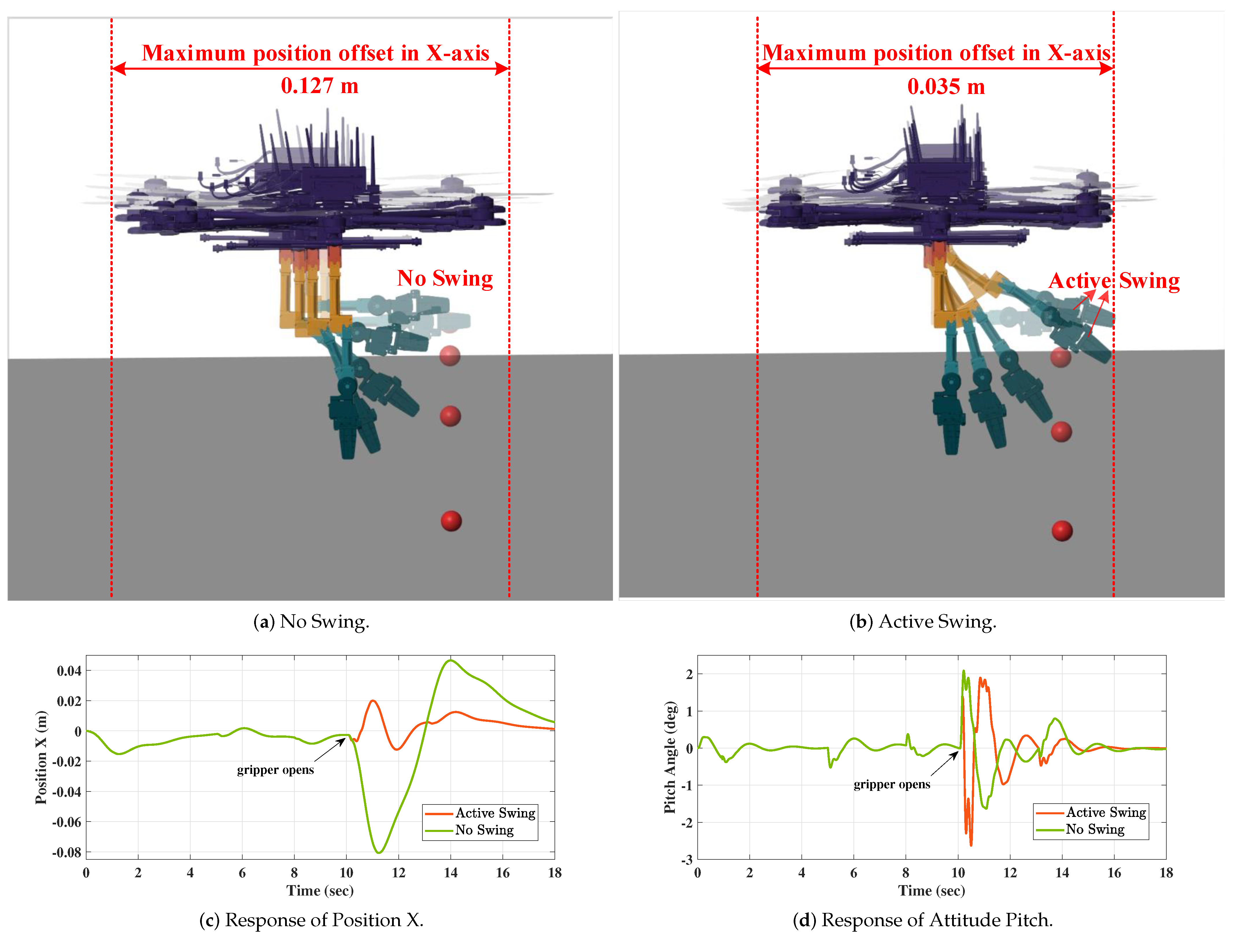
4.2. Simulation I: Keeping Stable in Pick and Place Scenario

In a pick and place scenario for UAM application, when a grabbed heavy object is suddenly dropped, the position and attitude stability of the UAM will be significantly affected. Under this working condition, this simulation needed to verify whether the UAM could be stably maintained at the moment the heavy object fell using the active swing of the manipulator. For this purpose, a set of comparative simulations were conducted. In the simulations, the hovering position of an UAM with a grabbed ball on the end-effector was set as p b _ d = [ 0 , 0 , 0 ] T and ψ d was set to 0. The gripper of the manipulator opened and the grabbed ball fell freely at 10 s. As a control group, the UAM’s manipulator executed no swing. As an experimental group, when the gripper of the manipulator opened, the manipulator executed an active swing to generate coupling disturbance torque to help the UAM maintain stability.
The results of Simulation I are presented in Figure 4. Figure 4a,b show the simulation snapshots of the control group and experimental group. Figure 4c and Figure 4d display the response of position X and attitude θ during the Simulation I, respectively.
From Figure 4, we can conclude that at the moment when the ball was dropped in the pick and place scenario, the active swing of the manipulator achieved better anti-disturbance and stability maintenance performance compared to no swing, and it significantly reduced the hovering position offset of UAM. When the gripper of the manipulator opened at 10 s and the ball began to fall freely, the additional control torque used to balance the ball caused the UAM’s attitude to tilt, thereby causing a position shift, as shown in Figure 4c,d. In this case, the coupling disturbance torque generated by the active swing of the manipulator could compensate and suppress the impact of this additional control torque, thereby significantly reducing the position shift and making the UAM more stable. Therefore, the simulation results verified the effectiveness of the active swing of the manipulator in maintaining the stability of the UAM in the pick and place scenario, and laid the foundation for the development of Simulation II.
On the other hand, the principle of using the active swing of the manipulator to generate coupling disturbance torque could also be used to provide the required tilting torque for UAMs and UAVs to perform quick attitude maneuvers, which has further research potential.

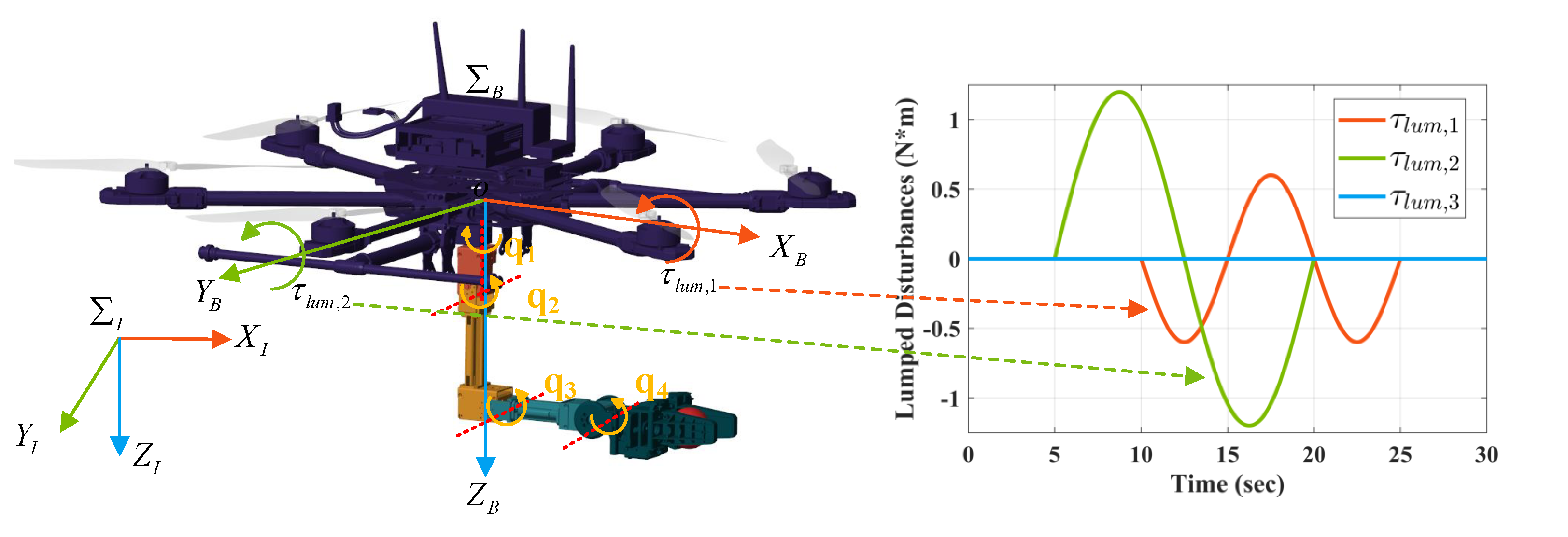
4.3. Simulation II: Suppressing Lumped Disturbances Using A A D C V C D

The real-world aerial environment imposes lumped disturbances on UAMs, attributable to factors such as gusts, unmodeled dynamics, and other external influences. In order to verify the suppression effect of the proposed AADC VCD on lumped disturbances, a set of comparative simulations were conducted. In the simulations, an UAM with a grabbed ball was also set to keep hovering at p b _ d = [ 0 , 0 , 0 ] T and ψ d was also set to 0. In the simulation, lumped disturbances were treated as random sinusoidal signals and commenced their influence on the unmanned aerial vehicle (UAM) at 5 s. As a control group, the UAM’s manipulator did not execute any swing and only relied on the robustness of the nominal control algorithm to resist lumped disturbances. As an experimental group, our proposed AADC VCD was used to compensate and suppress lumped disturbances. d s in Constrain 1 was set as: d s = 0 . In Constrain 2, q ̲ = [ π , 2.05 , 2.0 , 1.8 ] T and q ¯ = [ π , 2.05 , 1.53 , 2.0 ] T . W 1 = d i a g ( 3 , 3 , 3 ) and W 2 = d i a g ( 1 , 1 , 1 , 1 ) . Sequential quadratic programming (SQP) was utilized to solve the NLP formulated in Section 3.1. The expression of lumped disturbances is shown as τ l u m = 0.6 sin ( π ( t 1 10 ) 5 ) , 1.2 sin ( π ( t 2 5 ) 15 ) , 0.0 T , 10 t 1 25 , 5 t 2 20 , and its specific action form can be seen in Figure 5.
The results of simulation II are shown in Figure 6, Figure 7, Figure 8, Figure 9 and Figure 10. Figure 6 displays the simulation snapshots of the control group and experimental group. The response of position X,Y, and attitude ϕ , θ are illustrated in Figure 7. The total control torque and the motor speeds of the control group and experimental group are shown in Figure 8, respectively. Figure 9a shows the desired joint angles q ^ of the manipulator by solving NLP and the actual joint angles q of the manipulator, respectively. The desired generated coupling disturbance torque τ ^ l u m and the coupled disturbance torque   B τ ^ d e s generated by the active swing with AADC VCD are presented in Figure 9b. Figure 10 displays the changes in the objective function value during the AADC VCD simulation. Visible by the naked eye, our proposed AADC VCD performed much better than No Swing.
From Figure 6 and Figure 7, we can see that the AADC VCD we proposed showed a good performance in suppressing the lumped disturbances and significantly reduced the position offset caused by the lumped disturbances. This was because when the lumped disturbances started to act on the UAM, the ESO presented in Section 3.2 could accurately estimate the desired generated coupling disturbance torque and use it to construct the NLP. Then, by actively swinging to the desired joint angles q ^ , which is obtained by solving NLP, the generated coupling disturbance torque   B τ ^ d e s could directly compensate for the lumped disturbances τ ^ l u m , as illustrated in Figure 9.
On the other hand, from the smaller control torque and lower motor speed of AADC VCD in Figure 8, it can be seen that the proposed AADC VCD took full advantage of the UAM’s own manipulator and also effectively reduced the energy consumption during the suppression of lumped disturbances, which was conducive to improving the working endurance time of UAM. In addition, the mechanism of using the coupling disturbance generated by the active swing of the manipulator to compensate for the lumped disturbance is faster and more direct than the traditional compensation through the aerodynamic torque generated by the propeller, because the latter is subject to a slow aerodynamic response and other factors. Meanwhile, the variable load on the end-effector was also able to further improve the capability and limit of resisting the torque of the external lumped disturbance.

5. Conclusions

This paper proposed a novel active anti-disturbance control strategy for unmanned aerial manipulators, predicated on variable coupling disturbance compensation, which can realize the active disturbance rejection effect of “using the enemy’s strength against the enemy”, so that UAMs can maintain stability under multi-source disturbances. First, learning from the behavior of kangaroos that use the active wagging of their tail to generate torque to adjust their posture, we proposed using the coupling disturbance generated by the active swing of the UAM’s own manipulator as a control input signal for active disturbance rejection. Then, utilizing the proposed variable coupling disturbance model, we formulated the goal of active disturbance rejection as a nonlinear programming optimization problem under specific physical constraints. Solving this optimization problem could obtain the desired joint angles of the manipulator for active swinging. Finally, the coupling disturbance torque directly generated when the manipulator actively transitions to the predetermined desired joint angles could be used to compensate and suppress the other disturbances of the UAM, thereby achieving active and energy-saving anti-disturbance control effects. Combining the above components, we proposed the AADC VCD for UAMs to achieve active anti-disturbance. The effectiveness and superiority of the proposed AADC VCD were validated through two simulations, namely keeping stable in pick and place scenario and suppressing lumped disturbance using AADC VCD . In the two simulations, the proposed AADC VCD both showed good anti-disturbance and energy-saving performance, significantly reducing the position offset of the UAM caused by disturbances.
The principle of using the active swing of the manipulator to generate coupling disturbance torque as proposed in this article could also be used to provide the required tilting torque for UAMs and UAVs to perform quick attitude maneuvers, which has further research potential and will be the subject of the authors’ upcoming research.

Author Contributions

Conceptualization, H.L. and Z.L.; methodology, H.L.; software, H.L. and Q.X.; validation, H.L., T.W. and C.D.; formal analysis, H.L.; investigation, H.L.; resources, H.L. and Z.L; data curation, H.L., Y.Y. and X.Y.; writing—original draft preparation, H.L.; writing—review and editing, Z.L.; visualization, H.L., C.D., T.W. and Q.X.; supervision, Z.L.; project administration, Z.L., H.L., Y.Y. and X.Y.; funding acquisition, Z.L. All authors have read and agreed to the published version of the manuscript.

Funding

This research was partially supported by the National Natural Science Foundation of China under Grant 62273122, and by Heilongjiang Natural Science Foundation under Grant YQ2023F009.

Data Availability Statement

The data are not publicly available due to privacy.

Conflicts of Interest

Author Xinghu Yu was employed by the company Ningbo Institute of Intelligent Equipment Technology Co., Ltd. The remaining authors declare that the research was conducted in the absence of any commercial or financial relationships that could be construed as a potential conflict of interest.

References

  1. Ollero, A.; Tognon, M.; Suarez, A.; Lee, D.; Franchi, A. Past, Present, and Future of Aerial Robotic Manipulators. IEEE Trans. Robot. 2022, 38, 626–645. [Google Scholar] [CrossRef]
  2. Ruggiero, F.; Lippiello, V.; Ollero, A. Aerial Manipulation: A Literature Review. IEEE Robot. Autom. Lett. 2018, 3, 1957–1964. [Google Scholar] [CrossRef]
  3. Wang, M.; Chen, Z.; Guo, K.; Yu, X.; Zhang, Y.; Guo, L.; Wang, W. Millimeter-Level Pick and Peg-in-Hole Task Achieved by Aerial Manipulator. IEEE Trans. Robot. 2024, 40, 1242–1260. [Google Scholar] [CrossRef]
  4. Miyazaki, R.; Paul, H.; Kominami, T.; Martinez, R.R.; Shimonomura, K. Flying washer: Development of high-pressure washing aerial robot employing multirotor platform with add-on thrusters. Drones 2022, 6, 286. [Google Scholar] [CrossRef]
  5. Kutia, J.R.; Stol, K.A.; Xu, W. Aerial manipulator interactions with trees for canopy sampling. IEEE/ASME Trans. Mechatron. 2018, 23, 1740–1749. [Google Scholar] [CrossRef]
  6. Chen, Y.; Liang, J.; Wu, Y.; Miao, Z.; Zhang, H.; Wang, Y. Adaptive sliding-mode disturbance observer-based finite-time control for unmanned aerial manipulator with prescribed performance. IEEE Trans. Cybern. 2022, 53, 3263–3276. [Google Scholar] [CrossRef] [PubMed]
  7. Zhang, G.; He, Y.; Dai, B.; Gu, F.; Han, J.; Liu, G. Robust control of an aerial manipulator based on a variable inertia parameters model. IEEE Trans. Ind. Electron. 2019, 67, 9515–9525. [Google Scholar] [CrossRef]
  8. Shi, P.; Yu, X.; Yang, X.; Rodríguez-Andina, J.J.; Sun, W.; Gao, H. Composite Adaptive Synchronous Control of Dual-Drive Gantry Stage With Load Movement. IEEE Open J. Ind. Electron. Soc. 2023, 4, 63–74. [Google Scholar] [CrossRef]
  9. Li, H.; Li, Z.; Liu, J.; Zheng, X.; Yu, X.; Kaynak, O. Adaptive neural network backstepping control method for aerial manipulator based on coupling disturbance compensation. J. Frankl. Inst. 2024, 361, 106733. [Google Scholar] [CrossRef]
  10. Liu, Z.; Gao, H.; Yu, X.; Lin, W.; Qiu, J.; Rodríguez-Andina, J.J.; Qu, D. B-Spline Wavelet Neural-Network-Based Adaptive Control for Linear-Motor-Driven Systems via a Novel Gradient Descent Algorithm. IEEE Trans. Ind. Electron. 2024, 71, 1896–1905. [Google Scholar] [CrossRef]
  11. Buzzato, J.; Hernandes, A.; Becker, M.; Caurin, G.d.P. Aerial manipulation with six-axis force and torque sensor feedback compensation. In Proceedings of the 2018 Latin American Robotic Symposium, 2018 Brazilian Symposium on Robotics (SBR) and 2018 Workshop on Robotics in Education (WRE), Joao Pessoa, Brazil, 6–10 November 2018; IEEE: Piscataway, NJ, USA, 2018; pp. 158–163. [Google Scholar]
  12. Zhong, H.; Miao, Z.; Wang, Y.; Mao, J.; Li, L.; Zhang, H.; Chen, Y.; Fierro, R. A practical visual servo control for aerial manipulation using a spherical projection model. IEEE Trans. Ind. Electron. 2019, 67, 10564–10574. [Google Scholar] [CrossRef]
  13. Shi, P.; Sun, W.; Yang, X.; Rudas, I.J.; Gao, H. Master-Slave Synchronous Control of Dual-Drive Gantry Stage with Cogging Force Compensation. IEEE Trans. Syst. Man Cybern. Syst. 2023, 53, 216–225. [Google Scholar] [CrossRef]
  14. Cao, H.; Li, Y.; Liu, C.; Zhao, S. ESO-Based Robust and High-Precision Tracking Control for Aerial Manipulation. IEEE Trans. Autom. Sci. Eng. 2023, 21, 2139–2155. [Google Scholar] [CrossRef]
  15. Cao, H.; Wu, Y.; Wang, L. Adaptive NN motion control and predictive coordinate planning for aerial manipulators. Aerosp. Sci. Technol. 2022, 126, 107607. [Google Scholar] [CrossRef]
  16. Yu, Z.; Huang, Z.; Fu, J.; Jiang, X.; Xin, Y. Controller Design of Quadrotor UAVs with Suspended Payload Based on the Nested Saturation. Flight Control Detect. 2023, 6, 37–43. [Google Scholar]
  17. Pose, C.; Giribet, J.; Mas, I. Adaptive center-of-mass relocation for aerial manipulator fault tolerance. IEEE Robot. Autom. Lett. 2022, 7, 5583–5590. [Google Scholar] [CrossRef]
  18. Pose, C.; Giribet, J. Multirotor fault tolerance based on center-of-mass shifting in case of rotor failure. In Proceedings of the 2021 International Conference on Unmanned Aircraft Systems (ICUAS), Athens, Greece, 15–18 June 2021; IEEE: Piscataway, NJ, USA, 2021; pp. 38–46. [Google Scholar]
  19. Lee, S.J.; Jang, I.; Kim, H.J. Fail-safe flight of a fully-actuated quadrotor in a single motor failure. IEEE Robot. Autom. Lett. 2020, 5, 6403–6410. [Google Scholar] [CrossRef]
  20. Khamseh, H.B.; Janabi-Sharifi, F.; Abdessameud, A. Aerial manipulation—A literature survey. Robot. Auton. Syst. 2018, 107, 221–235. [Google Scholar] [CrossRef]
  21. Dong, W.; Ma, Z.; Sheng, X.; Zhu, X. Centimeter-level aerial assembly achieved with manipulating condition inference and compliance. IEEE/ASME Trans. Mechatron. 2021, 27, 1660–1671. [Google Scholar] [CrossRef]
  22. Eneh, J.N.; Nwafor, S.C.; Nnadozie, E.C.; Ani, O.A. Adaptive Fuzzy Sliding Mode Control for an Aerial Manipulator as a Payload on a Quadcopter. In Proceedings of the 2022 5th Information Technology for Education and Development (ITED), Abuja, Nigeria, 1–3 November 2022; IEEE: Piscataway, NJ, USA, 2022; pp. 1–6. [Google Scholar]
  23. Lee, D.; Seo, H.; Jang, I.; Lee, S.J.; Kim, H.J. Aerial manipulator pushing a movable structure using a DOB-based robust controller. IEEE Robot. Autom. Lett. 2020, 6, 723–730. [Google Scholar] [CrossRef]
  24. Li, T.; Li, S.; Sun, H.; Lv, D. The fixed-time observer-based adaptive tracking control for aerial flexible-joint robot with input saturation and output constraint. Drones 2023, 7, 348. [Google Scholar] [CrossRef]
  25. Zhuang, S.; Lei, D.; Yu, X.; Tong, M.; Lin, W.; Rodriguez-Andina, J.J.; Shi, Y.; Gao, H. Microinjection in Biomedical Applications: An Effortless Autonomous Omnidirectional Microinjection System. IEEE Ind. Electron. Mag. 2023, 2–15. [Google Scholar] [CrossRef]
  26. Wang, S.; Ma, Z.; Quan, F.; Chen, H. Impact Absorbing and Compensation for Heavy Object Catching with an Unmanned Aerial Manipulator. IEEE Robot. Autom. Lett. 2024, 9, 3656–3663. [Google Scholar] [CrossRef]
  27. Kangaroos Hopping Sequence. Available online: https://stock.adobe.com/images/kangaroos-hopping-sequence/265721560 (accessed on 22 March 2024).
  28. Gao, H.; Li, Z.; Yu, X.; Qiu, J. Hierarchical Multiobjective Heuristic for PCB Assembly Optimization in a Beam-Head Surface Mounter. IEEE Trans. Cybern. 2022, 52, 6911–6924. [Google Scholar] [CrossRef]
  29. Craig, J.J. Introduction to Robotics: Mechanics and Control; Pearson Educacion: Upper Saddle River, NJ, USA, 2005. [Google Scholar]
  30. Zheng, Q.; Gaol, L.Q.; Gao, Z. On stability analysis of active disturbance rejection control for nonlinear time-varying plants with unknown dynamics. In Proceedings of the 2007 46th IEEE Conference on Decision and Control, New Orleans, LA, USA, 12–14 December 2007; pp. 3501–3506. [Google Scholar]
  31. Lee, T. Robust Adaptive Attitude Tracking on SO(3) With an Application to a Quadrotor UAV. IEEE Trans. Control Syst. Technol. 2013, 21, 1924–1930. [Google Scholar]
  32. Miller, S.; Wendlandt, J. Real-time simulation of physical systems using simscape. MATLAB News and Notes, 9 August 2012; 1–13. [Google Scholar]
Figure 1. Kangaroo actively swings tail to maintain balance during jumping [27].
Electronics 13 01477 g001
Figure 2. The coordinate frame of a UAM.
Electronics 13 01477 g002
Figure 3. The simulated UAM in Simscape.
Electronics 13 01477 g003
Figure 4. The results of simulation I: (a) the snapshots of control group, (b) the snapshots of experimental group, (c) the response of Position X, and (d) the response of Attitude Pitch.
Electronics 13 01477 g004
Figure 5. The lumped disturbances acting on the UAM.
Electronics 13 01477 g005
Figure 6. The results of simulation II: (a) the snapshots of control group, (b) the snapshots of experimental group.
Electronics 13 01477 g006
Figure 7. The results of simulation II: (a) the response of Position X, (b) the response of Position Y, (c) the response of Attitude Roll, and (d) the response of Attitude Pitch.
Electronics 13 01477 g007
Figure 8. The results of simulation II: (a) total control torque of no swing, (b) total control torque of AADC VCD , (c) each motor speed of no swing, and (d) each motor speed of AADC VCD .
Electronics 13 01477 g008
Figure 9. The results of simulation II: (a) response of joint angles, (b) response of generated coupling disturbance torque.
Electronics 13 01477 g009
Figure 10. The results of simulation II: response of objective function value.
Electronics 13 01477 g010
Table 1. Physical parameters of the OpenMANIPULATOR-X.
ParameterValue
m m a n (kg)0.702
m 1 , 2 , 3 , 4 (kg)0.238, 0.123, 0.118, 0.224
  1 r c 1 (m)(−0.006794, 0.000253, −0.048813)
  2 r c 2 (m)(0.107084, −0.010616, 0.000467)
  3 r c 3 (m)(0.094329, 0.0000, 0.000489)
  4 r c 4 (m)(0.060527, −0.006058, −0.000021)
I 1 c 1 (kg·m2) 10 4 * 2.90202 0.00335 0.32543 0.00335 3.24158 0.02059 0.32543 0.02059 1.41275
I 2 c 2 (kg·m2)  10 4 * 0.33028 0.06189 0.01212 0.06189 1.84812 0.0002 0.01212 0.0002 1.89169
I 3 c 3 (kg·m2)  10 4 * 0.20796 0.00002 0.01064 0.00002 1.45545 0.00 0.01064 0.00 1.38574
I 4 c 4 (kg·m2)  10 4 * 1.43765 0.21123 0.00001 0.21123 2.12697 0.00485 0.00001 0.00485 1.80588
Table 2. Modified DH parameters of the OpenMANIPULATOR-X.
i α i 1 ( rad ) a i 1 ( m ) d i ( m ) θ i ( rad )
100.0120.0935 q 1
2 π 2 00 q 2 1.3855
300.130230 q 3 + 1.3855
400.1240 q 4
Disclaimer/Publisher’s Note: The statements, opinions and data contained in all publications are solely those of the individual author(s) and contributor(s) and not of MDPI and/or the editor(s). MDPI and/or the editor(s) disclaim responsibility for any injury to people or property resulting from any ideas, methods, instructions or products referred to in the content.

