Abstract
This comprehensive study presents a pioneering approach to limb lengthening, leveraging the advancements in wireless technology to enhance orthopedic healthcare. Historically, limb lengthening has been a response to discrepancies caused by fractures, diseases, or congenital defects, utilizing the body’s innate ability to regenerate bone and surrounding tissues. Traditionally, this involved external or internal fixation devices, such as the Ilizarov and Taylor Spatial frames or the Precice nail and Fitbone. The focal point of this research is the development and testing of a wireless intramedullary nail implant prototype, controlled remotely via a mobile application. This implant comprises a microcontroller, Bluetooth Low Energy module, a brushed DC motor controlled through an H-bridge, and a force sensor, all powered by medical-grade batteries. The integration of wireless technology facilitates patient autonomy in managing limb lengthening, reducing the need for frequent clinical visits. The methodology involves a detailed block diagram for our proposed work, outlining the process from treatment planning to the initiation of limb lengthening via the mobile application. Osteogenesis, the formation of new bone tissue, plays a crucial role in this procedure, which includes pre-surgery assessment, osteotomy, latency, distraction, consolidation, and removal phases. Key challenges addressed include custom battery design for efficient operation, size constraints, and overcoming signal interference due to the Faraday cage effect. Attenuation testing, simulating human tissue interaction, validates the implant’s connectivity. In conclusion, this research marks a significant stride in orthopedic care, demonstrating the feasibility of a wireless implant for limb lengthening. It highlights the potential benefits of reduced clinical visits, cost efficiency, and patient convenience. Despite limitations such as battery requirements and signal interference, this study opens avenues for future enhancements in patient-centered orthopedic treatments, signaling a transformative shift in managing limb length discrepancies.
1. Introduction
Limb lengthening, a practice dating back to the 20th century, was developed in response to discrepancies in limb length resulting from poorly healed fractures, diseases, or congenital defects. Over time, as individuals with congenital defects grow, these discrepancies often become more pronounced. This has led to an increased interest in limb lengthening for both personal and functional improvements. Limb lengthening leverages the body’s regenerative ability to grow new bones, soft tissues, ligaments, blood vessels, and nerves [1,2]. The process starts with an osteotomy, where the bone to be lengthened is surgically cut. The limb is then stabilized using external devices like the Ilizarov frame or Taylor Spatial frame, or internal devices such as intramedullary nails or plates. Modern techniques, such as the Precice nail or Fitbone, use specialized implants that are inserted into the bone and gradually lengthened with an external remote-control device [3]. A detailed illustration of leg length discrepancies treated with a lengthening device is shown in Figure 1. This paper focuses on enhancing the modern-day Precice nail or Fitbone method and aims to improve the existing wireless communication of the Fitbone implant by incorporating Bluetooth functionality. The proposed system includes an Android-compatible mobile application, a microcontroller, a Bluetooth receiver module, a DC motor powered by medical-grade coin batteries, and a force sensor. The mobile app will allow patients to connect to the implant controller, start and stop the lengthening process, monitor their prescription and extension progress, and receive updates from the surgeon. The motor, capable of bi-directional rotation, offers patients the option to reverse the extension in case of discomfort. The force sensor will be integrated to provide feedback to the microcontroller to ensure that the lengthening is proceeding as planned as well as provide a form of monitoring.
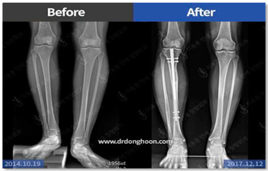
Figure 1.
Leg length discrepancies treated with a lengthening device.
Scope:
- A microcontroller and an H-bridge for bi-directional driving of a DC motor.
- Bluetooth Low Energy module (BLE) for wireless communication.
- Surgeon-provided prescriptions/schedules for patient’s daily extension.
- Patient self-monitoring and management of their extension schedule.
Key requirements:
- A web user interface for surgeons to update prescriptions/schedules.
- An emergency “stop” button in the mobile app, larger than the “start” button.
- Medical-grade batteries for reliable power supply.
- Directional control for the DC motor.
Constraints:
- Design dimensions within 60 mm length and 10 mm diameter.
- Batteries to support a minimum of 6 months (360 days) of operation.
- DC motor dimensions not exceeding 10 mm in diameter and 30 mm in length.
- All components must fit within the specified dimensions.
2. Literature Review
To better understand limb-lengthening procedures, three methods are explored as the focus for this project proposal: external fixation, internal fixation, and intramedullary nails.
2.1. Limb-Lengthening Methods
External fixation devices, such as the Ilizarov frame and Taylor Spatial frame, stabilize and align fractured bones. These devices allow for optimal positioning during healing, particularly useful in children and damaged skin fractures [4,5,6].
Advantages:
- Precise lengthening control.
- Correction of complex deformities.
- Minimal infection risks.
Disadvantages:
- Prolonged usage may cause discomfort and inconvenience.
- Requires strict patient compliance with adjustments.
Internal fixation is a surgical procedure used to stabilize fractured bones or correct bone deformities by physically reconnecting bone fragments or realigning bones using various implants such as screws, plates, rods, or nails. This method allows for direct fixation of the bone fragments or segments, facilitating proper healing and restoring structural integrity to the bone [7].
Advantages:
- Provides immediate stability post-surgery.
- Cost-effective compared to advanced system utilizing intramedullary nails.
Disadvantages:
- Larger incisions and tissue disruptions may lead to increased recovery times.
- Increased risks of complications.
- Adjustments require additional surgeries without external devices or remote controls.
Intramedullary nails include the Precice system, which utilizes a lengthening nail with a magnetic motor controlled by an External Remote Controller (ERC). Another popular intramedullary nail is the Fitbone, which employs an intramedullary nail with an electronic motor controlled by a different ERC using electric impulses [8].
Advantages:
- Less external hardware.
- Shorter treatment durations.
- Precise control.
- Earlier weight-bearing.
Disadvantages:
- Invasive surgery.
- Infection risks.
- Potential implant failures.
- Higher costs.
- May not match external methods’ ability to correct angular deformities.
2.2. Fitbone
Literature reviews performed with regard to Fitbone that mainly focused on its efficacy, safety, and mechanisms of action have been subjects of extensive investigation. Studies have not only evaluated its clinical outcomes but also delved into the biomechanical principles underlying its functionality. Fitbone operates through a self-expanding internal device, typically an intramedullary nail or rod, which is surgically inserted into the bone. This device contains an electronic motor controlled by an External Remote Controller (ERC). Unlike traditional methods, Fitbone employs electric impulses from the ERC to gradually elongate the nail’s internal motor. This mechanism coordinates the lengthening process over time, allowing for controlled and precise adjustments to the bone’s length. Biomechanical research elucidates how this process interacts with bone tissue, facilitating optimal bone healing and regeneration. Understanding these mechanisms is crucial for refining surgical techniques and rehabilitation protocols, ultimately enhancing patient outcomes and satisfaction [9].
2.3. Precice
The literature reviews performed on Precice not only evaluate its clinical outcomes but also explore its intricate mechanisms of action. Precice utilizes a lengthening nail containing a magnetic motor, which is surgically inserted into the bone canal. This motor is controlled by an External Remote Controller (ERC), facilitating precise control over the lengthening process. When the ERC is activated, the magnet inside the controller interacts with the motor in the nail, causing it to lengthen gradually. Unlike traditional methods, Precice’s mechanism allows for controlled adjustments without the need for additional surgeries. Biomechanical studies investigate how these mechanisms interact with bone tissue, influencing bone healing and regeneration. Understanding these intricate processes is essential for optimizing surgical techniques and rehabilitation protocols, leading to improved patient outcomes and satisfaction [10].
2.4. Complications in Connectivity
Recent studies have shown that there have been problems arising from connectivity between the External Remote Controller (ERC) and the implant, although only in a minority of cases, but still an important aspect of the procedure is to ensure that there is sufficient and consistent connectivity maintained during the lengthening to ensure that there are no complications and to keep track of the progress of the distraction. Two cases of connectivity problems were identified during the literature review stage, and it was pointed out that there was an insufficient connection to the receiver and also a defect in the external remote [11,12].
2.5. Wireless Technology
The rapid advancement of wireless technology has significantly impacted the medical industry, leading to numerous improvements and adaptations in medical devices and implants. Several wireless technologies have emerged, each offering unique benefits tailored to specific medical applications. Among these, Bluetooth Low Energy (BLE) has gained prominence for its versatility and compatibility with various medical devices [13].
- 1.
- Wi-Fi (802.11): Wi-Fi technology enables high-speed wireless data transmission over short to medium ranges. It is commonly used in hospital settings for connectivity between medical devices and hospital networks. However, Wi-Fi’s high power consumption and potential interference issues limit its suitability for implantable medical devices requiring long-term, low-power operation [14].
- 2.
- RFID (Radio-Frequency Identification): RFID technology utilizes electromagnetic fields to identify and track objects equipped with RFID tags. In the medical field, RFID is often employed for inventory management, patient tracking, and medication administration. While RFID offers benefits such as non-line-of-sight communication and passive operation, its limited range and data transfer rates may be inadequate for certain medical device applications [15].
- 3.
- NFC (Near-Field Communication): NFC technology enables short-range communication between devices, typically within a few centimeters. It is commonly used for contactless payments, access control, and data transfer between smartphones and wearable devices. NFC’s ease of use and security features make it suitable for applications requiring close-range communication, such as pairing medical devices with smartphones for data transfer [16].
- 4.
- Zigbee: Zigbee is a low-power wireless communication protocol designed for short-range, low-data-rate applications. It is commonly used in home automation, remote monitoring, and medical device connectivity. Zigbee’s mesh networking capability and low power consumption make it suitable for applications requiring long battery life and reliable communication in challenging environments [17].
- 5.
- Bluetooth Low Energy (BLE): BLE, also known as Bluetooth Smart, is a wireless communication technology designed for low-power, short-range applications. It offers benefits such as low power consumption, compatibility with smartphones and other consumer devices, and support for secure communication protocols. BLE is increasingly favored in the medical industry for its ability to enable seamless connectivity between medical devices and mobile applications, facilitating remote monitoring, data collection, and patient engagement [18,19].
The decision to use BLE in medical devices is driven by its combination of low power consumption, interoperability, and support for secure data transmission, making it well suited for a wide range of medical applications while ensuring patient safety and data privacy [20,21].
3. Our Proposed Work
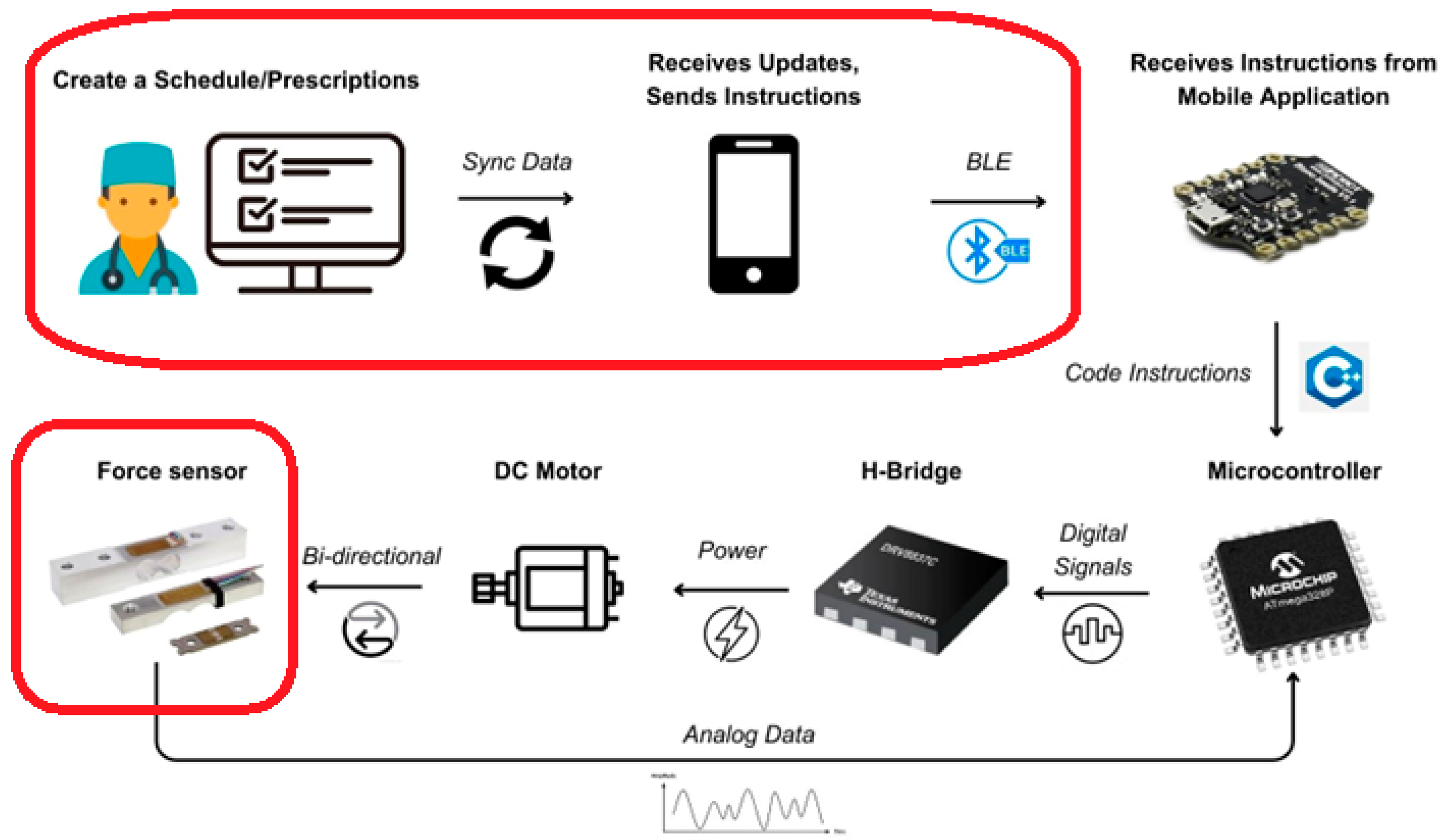
Our proposed architecture is meticulously outlined in Figure 2, which presents a comprehensive block diagram of the entire system. The process commences with a medical professional—either a physician or surgeon—crafting a personalized treatment plan tailored to the specific needs of each patient. This customized plan is then securely stored in a cloud-based repository, ensuring that sensitive medical information is kept confidential and accessible only to authorized personnel. Patients interact with this system through a dedicated mobile application. This app serves as a critical interface, enabling patients to access their individual treatment plans at their convenience. It empowers them to take an active role in managing their limb-lengthening process, fostering a sense of autonomy and engagement in their treatment. The initial step for the patient, upon deciding to commence the procedure, involves establishing a Bluetooth connection between their mobile device and the implant. This connection is pivotal as it serves as the communication channel through which commands and data are transmitted. Once the connection is successfully established, the patient can initiate the limb-lengthening procedure directly from the app. This is achieved by pressing the “Start” button, a simple yet effective user interface element designed for ease of use. Upon activation, the mobile app sends a signal via Bluetooth to the implant’s microcontroller. This microcontroller acts as the central processing unit of the implant, interpreting the signal and executing the necessary commands. It controls the H-bridge, a crucial component that regulates the direction and magnitude of current flowing to the DC motor. This motor, in turn, is responsible for the mechanical aspect of limb lengthening—it physically extends the implant in a controlled and precise manner. Simultaneously, a force sensor integrated into the system plays a vital role in monitoring the process. This sensor continuously measures the force being applied during the lengthening procedure, providing real-time feedback to the microcontroller. This feedback mechanism is essential for ensuring that the limb lengthening is occurring as planned, and the force applied is within the safe and effective range. It helps in adjusting the process dynamically, making real-time corrections as needed to maintain the optimal force level. This integration of sensing, control, and feedback forms the backbone of the system, ensuring that the limb-lengthening procedure is not only effective but also safe for the patient.
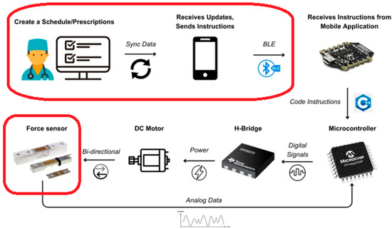
Figure 2.
Proposed architecture.
3.1. Osteogenesis
Osteogenesis is a critical biological process integral to the formation and maturation of new bone tissue. This complex process involves the transformation of cartilage or connective tissue into fully mineralized and mature bone. Playing a vital role in skeletal growth, repair, maintenance, and the regulation of key minerals like calcium and phosphate, osteogenesis is a continuous process throughout an individual’s life. It progresses through various stages of bone development and remodeling, influenced by genetic factors, hormonal dynamics, and mechanical stimuli. During osteogenesis, the surrounding soft tissues are also stretched as new bone is produced, contributing to the overall growth and repair of the skeletal system [22].
The surgical process of limb lengthening includes several critical steps:
- 1.
- Pre-Surgery Assessment: Before surgery, a thorough assessment of the patient’s leg is conducted. This involves analyzing the geometry and alignment of the leg, along with X-ray imaging, to determine suitability for limb lengthening. Factors like body weight are also considered to decide the appropriate osteotomy height [23,24,25,26,27].
- 2.
- Osteotomy Procedure: This is the actual surgical phase where the femur bone is carefully cut into two parts to accommodate the implant. The implant is then securely fixed using screws, ensuring stability and precision in the lengthening process.
- 3.
- Latency Period: Post-implantation, there is a short latency period of about five days. This time allows the leg to recover and prepare for the lengthening phase [28].
- 4.
- Distraction Phase: Starting on the fifth day after surgery, this phase involves gradually separating the two bone segments created during osteotomy. The implant facilitates this controlled separation, creating space for new bone tissue at a rate of about 1mm per day. The length of this phase varies, typically lasting several months depending on the required extension [29].
- 5.
- Consolidation Phase: Running parallel to the distraction phase, the consolidation phase sees the newly formed bone within the distracted gap solidifying. This crucial phase involves a slow maturation process, generally spanning four to six months, though this can vary based on the extent of the lengthening [30].
- 6.
- Removal Phase: The final phase occurs once the extended limb has fully healed, and the new bone tissue has matured. The implant is then surgically removed, marking the completion of the limb-lengthening procedure.
Each of these phases is vital to the success of the limb-lengthening process, ensuring safe and effective outcomes for patients undergoing this transformative surgical procedure.
3.2. Implant Design
The existing methods of Fitbone and Precice utilize an External Remote Controller (ERC) which controls the implant via magnetic fields to activate the lengthening and an External Remote Controller (ERC) which sends a signal to the implanted device, respectively. The engineering design of our proposed work is centered around a sophisticated implant, which is strategically housed within an intramedullary nail. Our proposed work utilizes a mobile phone and mobile application to be connected to the implant through Bluetooth Low Energy (BLE) as well as the addition of a force sensor to monitor the lengthening process. This implant is a composite of several critical components, each playing a distinct role in the functionality of the system. The key components include:
- 1.
- Microcontroller: This acts as the brain of the implant, managing the operations of all other components. It receives power from medical-grade batteries, which are connected to its voltage input. The microcontroller uses its digital input or output pins to control the various components, orchestrating their functions in a coordinated manner [31,32].
- 2.
- Bluetooth Low Energy (BLE) Module: This module is connected to the transmit and receive pins of the microcontroller. Its primary function is to facilitate wireless communication between the implant and the mobile device, enabling remote control and monitoring of the limb-lengthening process.
- 3.
- H-Bridge: This component is crucial for controlling the DC motor. It is linked to three digital input/output pins of the microcontroller. Two of these pins are equipped with pulse-width modulation functionality, which is essential for adjusting the direction and magnitude of the current flowing to the motor. The third pin is used to toggle the sleep mode of the H-bridge, an energy-saving feature that is important for the efficient operation of the system [33].
- 4.
- DC Motor: The motor, which is responsible for the physical movement required for limb extension, is controlled by the H-bridge. Given the need to maintain the extension position post-procedure and the constraints regarding size, the motor is custom-designed to meet the specific requirements of our proposed work [34,35].
- 5.
- Force Sensor: This sensor is connected to an analog input/output pin on the microcontroller. It plays a critical role in the system by measuring the force applied during the lengthening process. These data are vital for ensuring that the procedure is carried out safely and effectively, providing real-time feedback for necessary adjustments.
Each of these components is integral to the overall design and function of the implant. They work in unison to provide a controlled, safe, and effective limb-lengthening experience, leveraging modern technology to enhance medical procedures. The careful integration of these elements reflects our proposed work’s commitment to innovation, precision, and patient safety.
3.3. Proposed Wireless Integration
The integration of wireless technology into limb-lengthening procedures represents a significant advancement in patient-centered orthopedic care. Traditionally, limb lengthening has required patients to endure numerous clinical visits for manual adjustments, a process that can be taxing both in terms of time and physical exertion. The proposed introduction of Bluetooth-enabled control systems aims to revolutionize this approach [13,18]:
- Enhanced Patient Control and Autonomy: The key to this innovation is the use of a dedicated mobile application, which allows patients to independently initiate and manage the limb-lengthening process, marking a significant advancement in medical care.
- Significant Reduction in Clinic Visits: The introduction of the technology greatly reduces the need for frequent in-person clinic visits, a change that promises to alleviate the logistical and physical burdens typically associated with traditional limb-lengthening methods.
- Unprecedented Comfort and Flexibility: The mobile application introduces a new level of comfort and convenience, allowing patients to begin their treatment while accommodating their schedule.
- Potential Reduction in Healthcare Costs: With minimized requirements for frequent clinical visits, patients could notably lower the costs associated with limb lengthening, making the procedure more financially accessible to a wider patient demographic.
- Contribution to Sustainability: The use of energy-efficient Bluetooth technology can contribute to lower energy consumption, aligning with the increasing need for sustainable medical practices through reduced energy consumption.
- Support for Psychological Well-being: Remote management of the treatment process not only elevates the standard of care but also helps to bolster the psychological well-being of patients by providing them more control over their treatment journey, thereby minimizing disruptions in their daily lives.
This proposal, therefore, stands as a testament to the evolving landscape of orthopedic care, where technological innovation is harnessed to improve both the effectiveness and the human experience of medical treatments.
3.4. Proposed Active Feedback Control
The proposed active feedback control system is a pivotal element in the design and development of the limb-lengthening implant. This system amalgamates various components, effectively merging the implant’s mechanical design with a sophisticated control mechanism. The feedback control system plays an indispensable role in monitoring and regulating the force levels within the implant, ensuring that the force exerted during the lengthening process remains within a safe and effective range. This system remains operative not only when the implant is in a sleep state but also becomes crucial during the active lengthening phase. As the implant is programmed to extend by 1 mm daily, the system continuously gauges the force exerted. Should the force at any time fall below a pre-set threshold while the patient is active, it signals a potential malfunction or deviation from the planned procedure. To counter such anomalies, the system automatically activates the motor to readjust the force back within the desired parameters. This automated correction mechanism is integral to maintaining the implant’s performance, thereby ensuring the safety and well-being of the patient. Furthermore, this feedback control system provides essential data to healthcare providers, allowing for timely intervention and adjustment if necessary. Patients are also kept informed about any adjustments or anomalies, fostering transparency and trust in the treatment process [32]. Ensuring safety in the design and application of limb-lengthening implants is paramount, involving a few critical considerations. First, biomechanical compatibility is essential; the implant must apply forces that do not compromise the structural integrity of the bone or the surrounding tissues. In order to determine safe force thresholds that the bone can sustain without running the danger of harm or excessive stress, biomechanical simulations and testing are required. Strategies for mitigating risk are also essential. The system should be designed with fail-safes to prevent over-extension or excessive force application, possibly by setting strict upper limits on the force exerted by the motor and incorporating real-time monitoring to promptly detect and correct any deviations from these limits. An important factor in the implant’s overall safety is material safety. To reduce the possibility of rejection, infection, or unfavorable reactions, the materials must be biocompatible. Their long-term stability and degrading behavior must also be carefully considered to make sure they do not eventually become dangerous to health. A limb-lengthening implant is considered effective if it can accomplish desired growth rates in a predetermined amount of time and can reliably extend the patient’s limb to a predetermined amount each day (e.g., 1 mm per day) without causing pain or discomfort. Additionally, the effectiveness of the feedback control system is critical, particularly its adaptability to changing conditions such as increased resistance due to tissue healing or other factors, requiring automatic adjustments to maintain the desired extension rate. The ultimate measure of the system’s efficacy is clinical outcomes, which include maintaining limb function, patient mobility, and overall quality of life after treatment in addition to attaining the intended limb length.
3.5. Proposed User Interface
The user interface (UI) design for the mobile application associated with the limb-lengthening implant system is meticulously crafted to ensure that patients can easily navigate through the app, providing a streamlined and intuitive user experience. Our proposed design highlights the main pages that should be present in the application. The “Main Page”, the entry point of the application, is where patients are greeted with the option to either log in to their existing account or access the sign-up page to create a new one. This page is designed to be straightforward and user-friendly, ensuring ease of access for all users regardless of their familiarity with technology. On the “Sign-up Page”, new users can create their account. The sign-up process is simplified to encourage ease of use, asking for essential information required to personalize the treatment and ensure secure access. Upon successful login, patients are directed to the “Main Activity Page”. This page is the hub of the application, displaying crucial information about the patient’s treatment plan, progress, and any updates or notifications. It also includes functionality to scan for nearby Bluetooth Low Energy devices, enabling the implant to connect wirelessly with the app. The “Bluetooth Device Scanning and Selection” pop-up menu appears when the app is scanning for Bluetooth devices. It displays a list of available devices in the vicinity, allowing the patient to select and connect to their specific implant. The display is organized in a clear list format for easy selection and pairing. Overall, the UI is designed with a focus on accessibility and efficiency. It ensures that patients can easily manage their limb-lengthening procedure, access their treatment information, and connect with their implant device without any hassle. The clear layout and intuitive navigation of the application aim to enhance the patient’s experience, making the management of their medical treatment as seamless as possible.
4. Measurement Results
4.1. Prototype Design
Schematic designs are essential in the development of complex projects like the one described here, as they provide a detailed and visual representation of how various components and modules are interconnected. These schematics are not just tools for visualization but are fundamental in guiding the creation and understanding of both the hardware and software aspects of the system. The primary function of a schematic is to offer a clear and organized view of the circuit or system’s design. This visualization is crucial for understanding the flow of the circuit, how each component interacts with others, and the overall functionality of the system. It helps in identifying the connections and relationships between different parts, making the assembly process more straightforward and efficient. Another significant advantage of using schematic designs is their role in identifying potential design flaws early in the development process. By providing a detailed overview of the circuit, schematics allow engineers and developers to spot and rectify errors before the physical implementation of the circuit, saving substantial time and resources that might otherwise be spent on troubleshooting post-implementation. In the context of software development, schematics are invaluable for debugging and coding. They assist in determining which specific pins the components are connected to, aiding in the coding process, particularly in selecting the correct pins for specific functions like pulse-width modulation (PWM) to control the motor speed and the H-bridge’s polarization.
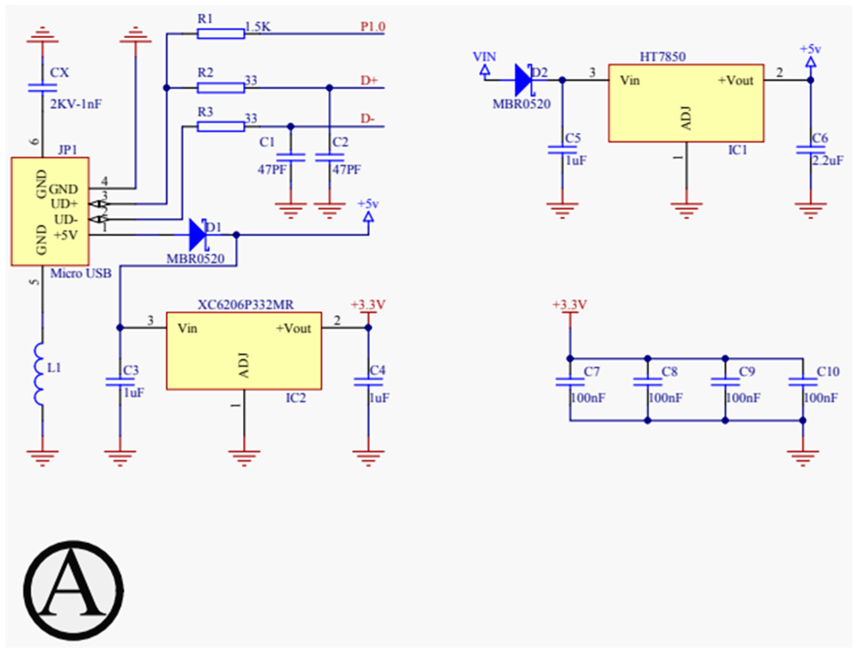
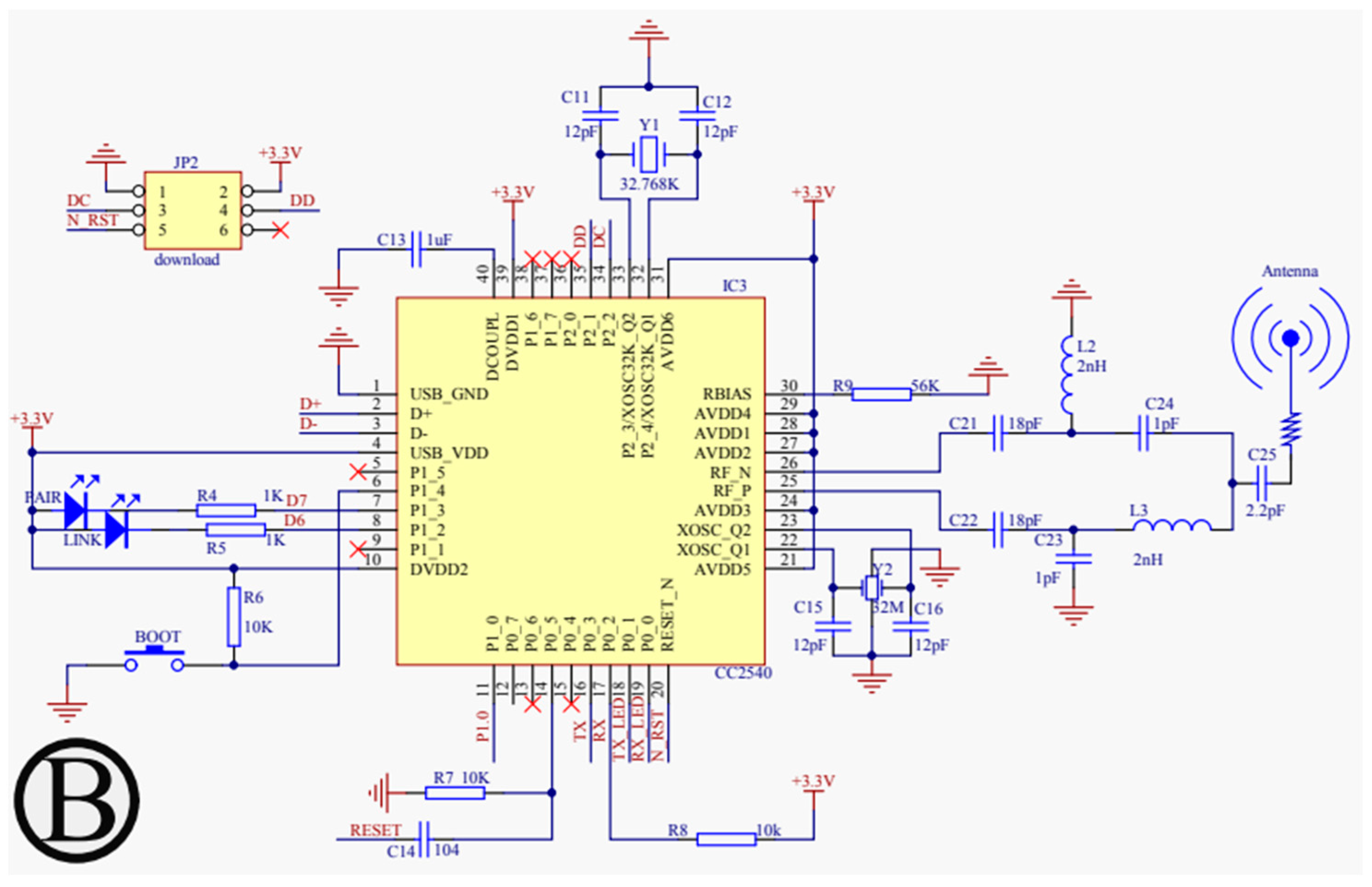
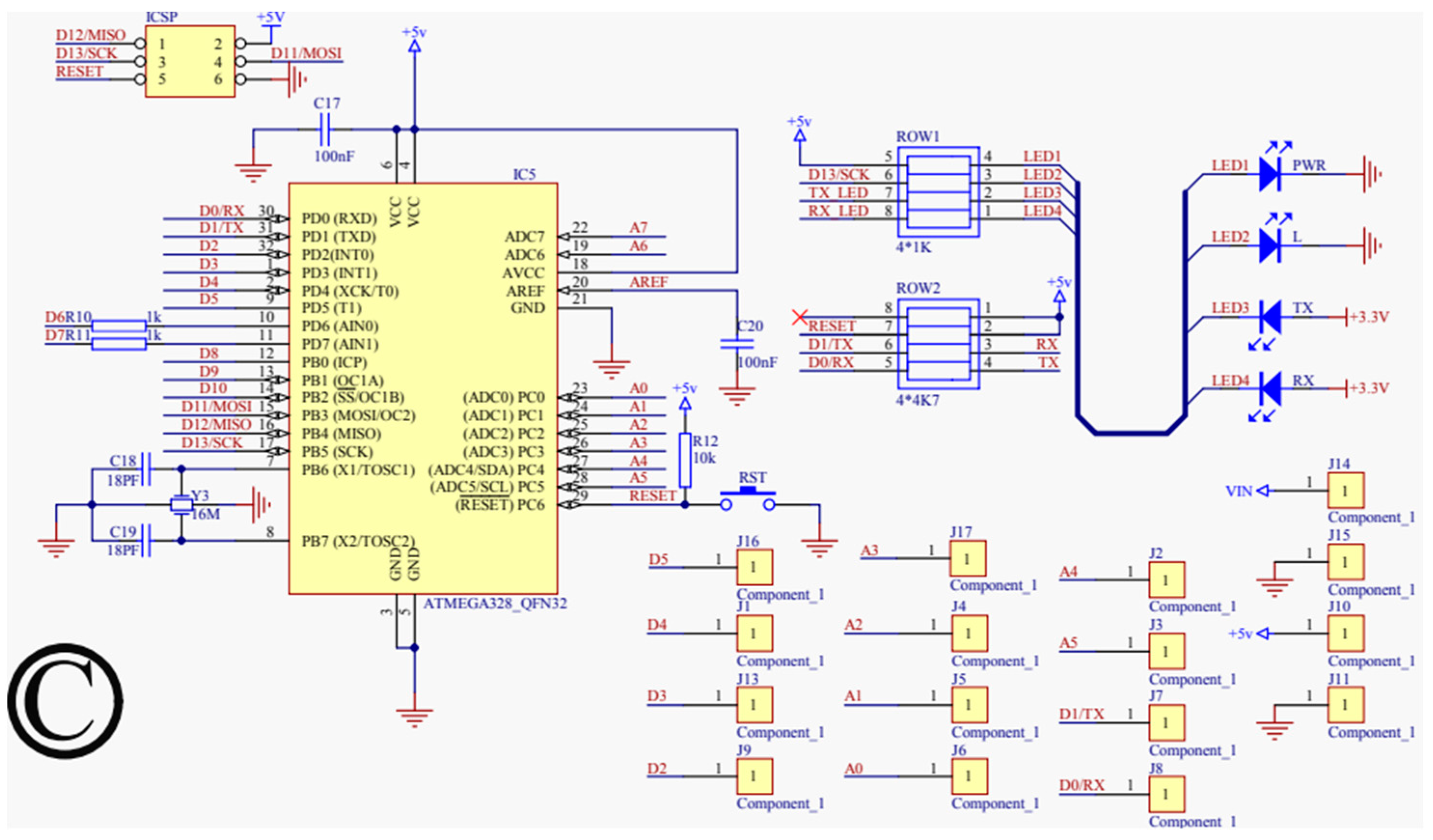
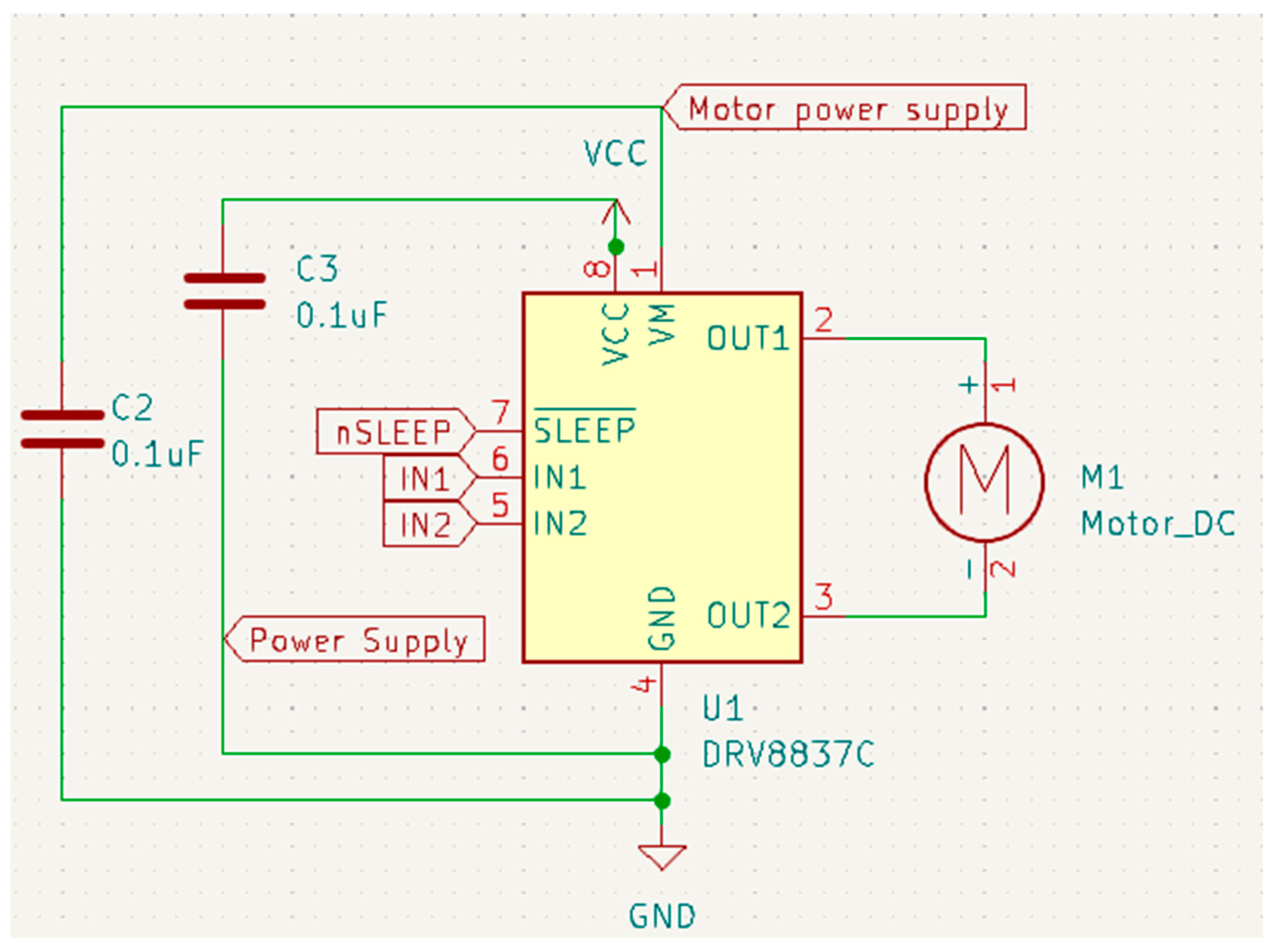
For our proposed work, the schematic design illustrated in Figure 3, Figure 4, Figure 5 and Figure 6 has been instrumental in mapping out the necessary connections for the Power Module shown in Figure 3, the Bluetooth module CC2540 shown in Figure 4, the Beetle BLE microcontroller ATMEGA328_QFN32 shown in Figure 5, and the H-bridge DRV8837C with the DC motor shown in Figure 6. The DRV8837C H-bridge, a critical component of the system, requires specific connections to the Beetle BLE for proper functionality. The “IN1” and “IN2” pins of the DRV8837C must be connected to the Beetle BLE’s PWM-capable digital pins “D3” and “D5”. Additionally, the sleep mode of the DRV8837C is controlled via the digital pin “D2” of the Beetle BLE. The VCC and Ground of the DRV8837C are connected to the 5V pin and Ground of the Beetle BLE, respectively [31,32,33,34,35].

Figure 3.
Schematic design for power configuration.
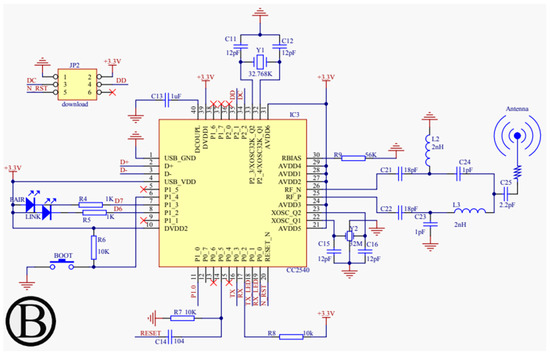
Figure 4.
Schematic design of the power configuration for the Bluetooth Low Energy module (CC2540).
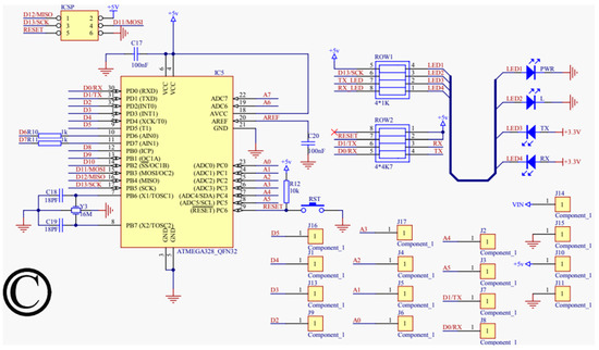
Figure 5.
Schematic design for the microprocessor (ATMEGA328_QFN32).

Figure 6.
Schematic design for the H-bridge (DRV8837C).
4.2. Testing Phase
The use of a breadboard for the initial implementation of the circuit is a strategic and effective approach in the development process of electronic projects. A breadboard is an invaluable tool for testing and verifying the functionality of circuits in real time, offering several key advantages:
- Ease of Design Error Identification and Rectification: The breadboard allows for easy assembly and disassembly of components. This flexibility is crucial in quickly identifying and rectifying design errors, significantly reducing the time and effort needed compared to working directly with a prototype board.
- Facilitates Circuit Modifications: Given its non-permanent nature, a breadboard makes modifying the circuit straightforward. Changes can be made without the need for desoldering, which is especially useful during the iterative process of testing and refining the design.
- Clearer Implementation Design for Soldering: Working with a breadboard provides a clear and physical representation of the circuit. This visual aid is beneficial when it comes time to transfer the circuit onto a prototype board for soldering, as it offers a tried and tested template to follow.
- Minimizing Risk to Final Components: During the testing phase, the use of a breadboard minimizes potential damage to final and more expensive components. In our proposed work, substituting the Beetle BLE with the Arduino Bluno for breadboard testing is a prudent decision. This substitution prevents potential damage to the Beetle BLE, a crucial component of our proposed work. The Arduino Bluno offers similar functionality, allowing for accurate testing without risking the integrity of the final component.
Overall, the utilization of a breadboard in the initial stages of circuit implementation is a smart and practical choice. It provides a risk-free environment to test, troubleshoot, and perfect the circuit before moving on to the more permanent and complex task of assembling the final prototype. This approach not only ensures the functionality and reliability of the design but also conserves resources and safeguards the more delicate final components of our proposed work.
4.3. Force Sensor and Actuator Setup
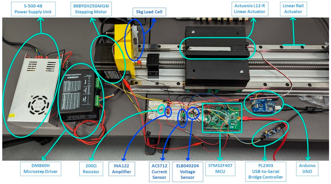
The successful development of the limb-lengthening prototype, as detailed in our proposed work, highlights key advancements in medical technology. The prototype’s force sensor and actuator setup, illustrated in Figure 7, plays a crucial role in the limb-lengthening process. Through meticulous calibrations and adjustments, the following specifications were achieved:

Figure 7.
Force sensor and actuator setup.
- 1.
- Motor Speed: The motor operates at a controlled pace of 0.1 mm per second. This specific speed was chosen to enable patients to visibly track the limb-lengthening progress, allowing them to observe and request adjustments if needed.
- 2.
- Lengthening Schedule: The lengthening procedure is designed to be flexible, with a prescribed schedule that can range from a minimum of three months to a maximum of six months. This adaptability caters to individual patient needs and variations in treatment plans.
- 3.
- Extension Parameters: The default extension length is set at 1 mm per extension, with the total permissible length of extension capped at 60 mm for the human body. Consequently, a complete and smooth extension process is expected to span approximately 60 days, ensuring gradual and controlled limb lengthening.
- 4.
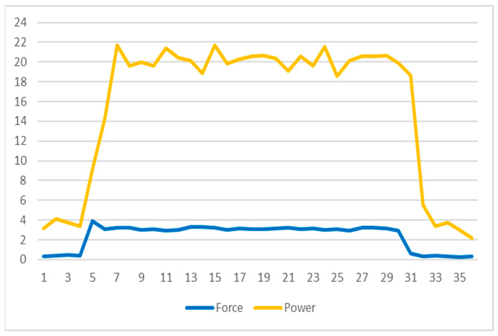
- Power Consumption: A significant observation, as seen in Figure 8, is the noticeable increase in power consumption when the DC motor engages to apply the target force as detected by the force sensor. This surge contrasts sharply with the motor’s power usage in standby mode, emphasizing the need for efficient power management. Managing this power consumption is vital for the sustainability and functionality of the implant over the treatment duration.
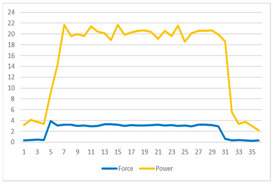 Figure 8. Force and power graph.
These specifications and observations underscore the importance of precision and efficiency in medical device design, especially in systems like limb-lengthening implants that require a delicate balance between mechanical performance and patient safety. Our proposed work focuses on careful speed control, flexible treatment scheduling, and efficient power management reflecting a thoughtful approach to enhancing patient experience and treatment outcomes in orthopedic care.
The observation noted in Figure 8 regarding power consumption is a critical aspect of the limb-lengthening prototype’s functionality. It highlights a stark contrast in the power usage of the DC motor during the active extension period compared to its standby mode. This distinction is significant for several reasons:
- 1.
- Energy Efficiency: The increase in power consumption during the motor’s active phase underscores the importance of energy efficiency in the design. Since the device is battery-powered, optimizing power usage is crucial for the longevity and sustainability of the implant.
- 2.
- Operational Management: Understanding the different power requirements between active and standby modes is essential for managing the operational aspects of the implant. This includes planning for battery life, anticipating the need for battery replacement or recharging, and ensuring the device remains functional throughout the required treatment period.
- 3.
- Patient Safety and Comfort: The variance in power consumption also relates to patient safety and comfort. The motor’s activity must be balanced to provide effective limb lengthening without causing discomfort or harm to the patient, which requires careful calibration of the motor’s power output.
- 4.
- Design Implications: The observed power consumption patterns may influence future design improvements, such as implementing more energy-efficient motors, optimizing circuitry for lower power usage, or exploring alternative energy sources.
In conclusion, the data presented in Figure 5 not only inform the efficiency and safety parameters but also provide valuable insights for future enhancements in medical implant technology, particularly in the realm of orthopedic treatments like limb lengthening.
4.4. Mobile Application
The next phase of our proposed work involves the development of a fully functional mobile application capable of detecting and connecting to Bluetooth devices, primarily the Arduino Bluno or Beetle BLE. This application will control the circuit by sending and receiving information, playing a critical role in the system’s functionality. Figure 9 shows the primary classes in the application, from left to right.
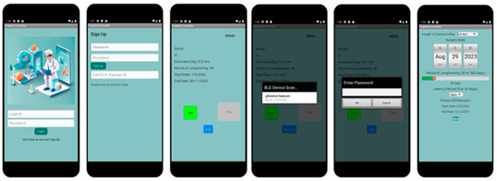
Figure 9.
Proposed design of mobile application.
The development of the mobile application begins with the creation of a Main Menu for user navigation, ensuring security by requiring patients to sign up for an account or log in each time they use the application. However, the absence of a cloud-based system limits backend database functionality for login verification and user account creation.
- User Authentication and Navigation: At the forefront of the application is the Main Menu, designed for straightforward navigation. It emphasizes user security by incorporating features for account creation and login, ensuring only authorized access. The absence of a cloud-based backend presents limitations in user verification and data storage, necessitating alternative solutions for secure and efficient user management.
- Main_Menu Class: Utilizes an OnClickListener function, facilitating navigation to the MainActivity class for returning users, and to the Sign_Up class for new account setups. This design ensures ease of access to the application’s main functionalities.
- Sign_Up Class: Features a password validation function to maintain account security. It underscores the application’s commitment to protecting user data while simplifying the account creation process.
- Core Functionality and Connectivity: The MainActivity class acts as the central hub for the application, connecting users to their treatment protocols via Bluetooth communication with the Arduino boards. This setup guarantees high-fidelity data transfer and seamless operation between the mobile app and the implant.
- BlunoLibrary Class: Manages the scanning of nearby Bluetooth devices, enhancing user interaction by providing real-time feedback on connection statuses such as “Connected” and “Scanning”.
- Admin_Page Class: Offers an exclusive interface for medical professionals to adjust critical parameters like motor speed and torque, ensuring tailored treatment plans for each patient.
- User Interface Design: The application’s interface is meticulously crafted to support user engagement and interaction. It incorporates several UI elements designed to facilitate easy control over the limb-lengthening process, from initiation to adjustment.
- Main Page UI: Serves as the gateway for user interaction, offering options for login and account registration. This interface is streamlined to accommodate users with varying levels of tech proficiency.
- Device Scan List UI: Allows patients to select their implant device from a list of available Bluetooth connections, streamlining the pairing process to initiate or halt the limb lengthening as needed.
- Conclusion and Enhancement Strategy: This section has outlined the comprehensive design and functionality of the mobile application intended to complement the limb-lengthening implant. By dividing the development process into distinct segments, we have aimed to enhance clarity and readability, addressing the reviewer’s feedback effectively. Future iterations will explore integrating cloud-based solutions for improved data management and user verification, ensuring the application’s scalability and security.
4.5. Attenuation Testing
Attenuation testing is vital to understand signal strength and integrity, especially for an implant device that operates within the human body. This testing simulated various environmental conditions to assess how they affected the Bluetooth signal’s strength and connectivity.
4.5.1. First Test Setup
The initial test setup involved a prototype locked inside an airtight container submerged in saline solution, as shown in Figure 10. This setup simulated the human body’s impact on wireless communications, particularly the potential for interference or signal degradation by different materials, including the surgical stainless steel of the Fitbone implant [36].
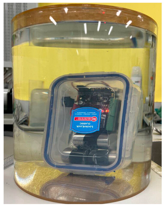
Figure 10.
Airtight container submerged in saline solution for attenuation test.
4.5.2. Second Test Setup
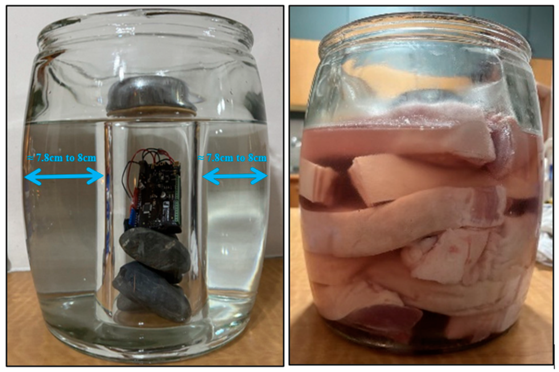
A second test setup used pork meat within a large glass jar to better simulate human muscle and tissue, aiming for more reliable attenuation test results, depicted in Figure 11. This setup allowed for an open space between the jar’s outer surface and a smaller glass cylinder, enabling a thorough assessment of Bluetooth signal strength under various conditions. This setup allowed for an open space of approximately 7.8 cm to 8 cm between the outer surface of the cylinder and the jar, facilitating Bluetooth signal strength assessment and the possible introduction of various materials to test Bluetooth signals under different conditions. Pork meat, chosen for its similarity to human meat in composition, including muscle tissue and fat distribution, served as a primary medium for testing Bluetooth signal strength.
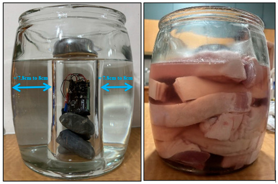
Figure 11.
Meat submerged in saline solution in a glass jar.
While both test setups provide a close approximation, it is crucial to recognize that there are inherent differences between pork and human tissues. Additionally, saline solution, commonly used to mimic bodily fluids, was employed as a medium to test different signal strengths of Bluetooth transmission. This choice aligns with medical and biological research practices, where realistic simulations of bodily fluids are necessary.
4.6. Attenuation Test Results
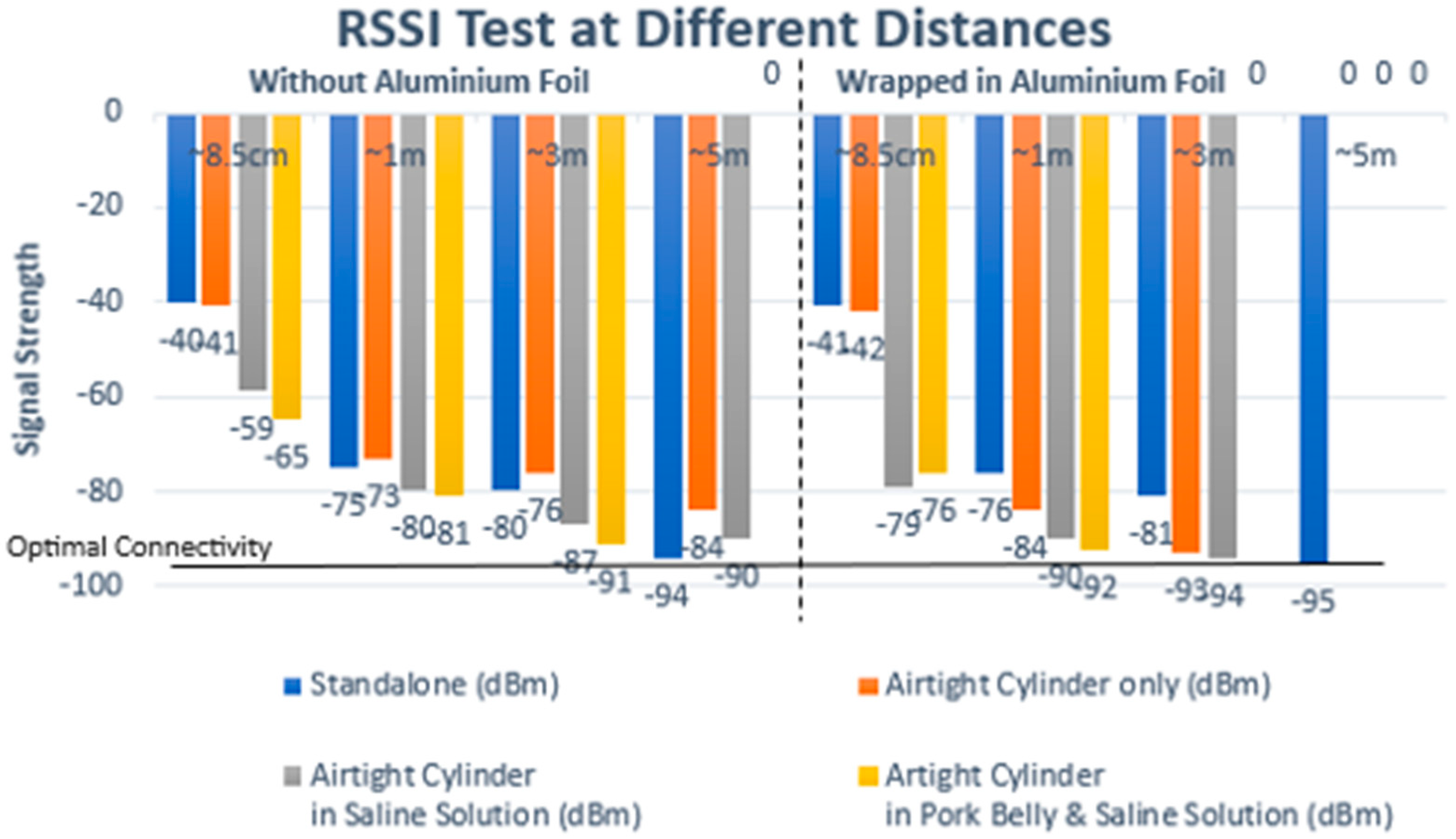
With the initial test setup, only containing saline solution, the results indicate that the implant was able to connect successfully up to 5 m without any interference or medium between the implant and the mobile device, as shown in Figure 12 and Table 1. However, connectivity issues surfaced when aluminum foil was introduced into the setup by wrapping the implant and the airtight container that it was sealed in. Any result above 98 dBm was taken to be a failed connection.
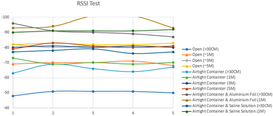
Figure 12.
Attenuation testing results: successful connection up to 5 m and the impact of aluminum foil wrapping on signal degradation.

Table 1.
Values for different attenuation test conditions in Figure 10: attenuation test results above 95 dBm are noted to present connectivity challenges.
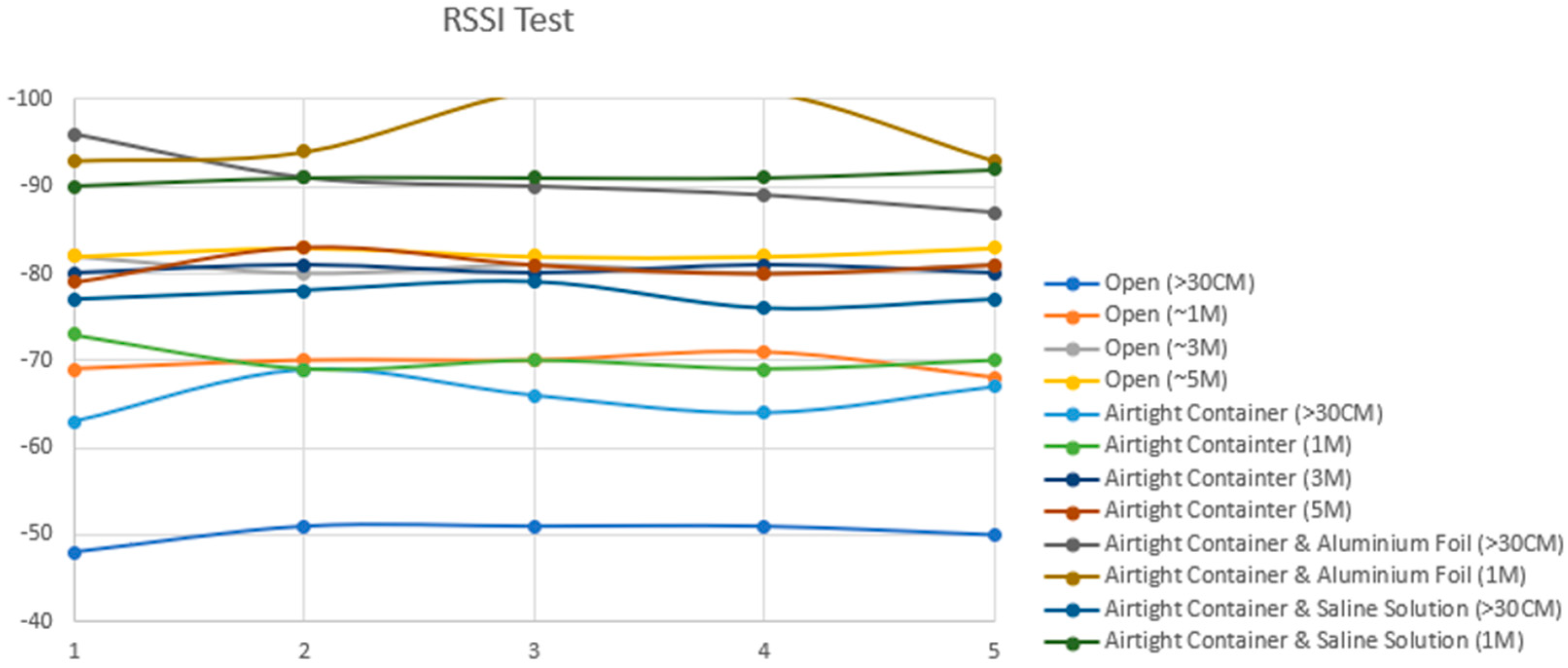
As depicted in Table 2, the recorded results provide insights into Bluetooth signal strengths across various testing scenarios. Standalone testing involved the signal strength testing of the Arduino Bluno without the cylinder or the large jar. The Received Signal Strength Indicator (RSSI) analysis revealed that the Bluetooth signal exhibited its weakest strength when the circuit design was encased in aluminum foil and surrounded by a combination of pork meat and saline solution. Notably, at the farthest distance measured—5 m away from the experimental layout—the Bluetooth signal experienced frequent disconnection (D/C) instances, particularly evident when the circuit was wrapped in aluminum foil. However, even in challenging scenarios, a wireless connection through Bluetooth to the implant remained viable at one meter from the device, as indicated by an RSSI value of −92 dBm in scenario seven. This crucial result implies that achieving a Bluetooth Low Energy connection is feasible when the patient’s Android phone is positioned directly atop the limb undergoing extension. Nevertheless, it is noteworthy that the mobile device that houses the mobile application used to control the implant must not exceed one meter from the implant to maintain a stable connection, as shown in Figure 13.
Table 2.
Received Signal Strength Indicator (RSSI) results for testing conditions in Figure 11: results show a maximum of 3 m connectivity distance would be optimal to avoid loss of connection.
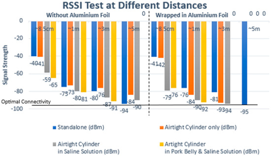
Figure 13.
Graph results for RSSI in Table 2.
Testing Conditions and Results:
- The open condition, with the prototype outside of the airtight container, served as a control for testing baseline signal strength.
- Subsequent tests involved encasing the prototype in an airtight container, with and without submersion in saline solution, to mimic the effect of body tissues on signal transmission.
- The prototype was then wrapped in aluminum foil while inside the container to simulate a Faraday cage scenario, highlighting the challenge of signal transmission through metal enclosures.
- The results indicated significant signal attenuation only in the aluminum foil-wrapped scenario, confirming the Faraday cage effect’s impact.
5. Discussion
In the development and testing of our wireless intramedullary nail implant prototype, our findings have illuminated several key aspects of integrating advanced technology into orthopedic care, particularly in limb-lengthening procedures. The prototype has successfully demonstrated controlled limb lengthening at a rate of 0.1 mm per s, which is in line with the introduction’s goals and demonstrates our progress beyond conventional techniques such as the Fitbone, Taylor Spatial Frame, Ilizarov frame, and Precice nail (as mentioned in Section 1 and Section 2.1) [1,2,3,8]. The customization and integration of Bluetooth Low Energy (BLE) for wireless communication, as well as the inclusion of a force sensor for active feedback control, mark a significant leap in facilitating patient autonomy and reducing the need for frequent clinical visits. This method directly addresses the issues and constraints seen in current systems, like the Fitbone and Precice implants, which lack real-time monitoring capabilities and depend on External Remote Controllers [9,10,12]. Our work provides a prototype that encapsulates these developments, supporting the literature’s call for innovations that improve the accuracy and patient-friendliness of limb-lengthening procedures [11,12]. Furthermore, the prototype’s performance during attenuation testing underscores the feasibility of maintaining effective wireless connectivity within the human body, despite the challenges posed by signal interference and the Faraday cage effect. This finding is critical, as it validates the core premise of our study—that wireless technology can be used to enhance the process of limb lengthening. This hypothesis was supported by our analysis of the state of biomedical implants and wireless technologies at the time [13,14,15,16,17,18,19,20,21]. The prototype’s usefulness in real-world clinical situations appears to be promising given the effective transmission in both saline solution and pig meat simulations, which addresses the connectivity issues raised in previous studies.
Design Recommendations
This proposed work encountered several limitations and challenges that required innovative solutions:
- 1.
- Custom-Designed Battery: The implant’s efficient operation at a low power threshold necessitated a custom-designed battery. This battery needed to be capable of sustaining the implant’s components, including the motor, for approximately two months, posing a challenge in terms of power management and longevity.
- 2.
- Prototype Scale vs. Final Product: The prototype was larger than the intended final product, raising concerns about potential inaccuracies in readings from various modules and sensors due to size-based discrepancies. This discrepancy necessitated further refinement of the design to ensure accuracy and functionality at a reduced scale.
- 3.
- Custom-Sized Modules Requirement: The need for custom-sized modules, like the microcontroller and Bluetooth module, could potentially impact the precision of data acquisition and the overall functionality of the system.
- 4.
- Faraday Cage Effect: An unexpected challenge arose from the metal casing of the implant, which acted as a Faraday cage, obstructing signal transmission. To mitigate this, the implant’s design had to be revised to include an external antenna. However, this solution brought forth additional concerns regarding the risk of infection or allergic reactions among implant recipients.
The attenuation testing results demonstrate reliable connectivity between both the implant and the mobile device using Bluetooth Low Energy (BLE). The versatility of the mobile application enables seamless troubleshooting and adjustment, allowing patients to manage their treatment remotely. Additionally, the application provides a secondary benefit by empowering medical professionals to modify treatment parameters without requiring patients to return to the hospital or clinic for adjustments.
In conclusion, our proposed work’s journey from concept to prototype testing highlights the complexity and challenges of integrating advanced technology into medical devices. The successful implementation of various components, from the mobile application to the Arduino board and the physical prototype, demonstrates the proposed work’s potential to significantly improve limb-lengthening procedures. However, the encountered challenges emphasize the need for ongoing innovation and careful consideration in the field of medical implant technology, particularly in addressing power management, size constraints, and ensuring reliable communication within the human body [37].
6. Conclusions
As this study has shown, limb-lengthening treatments with wireless technology represent a significant advancement in orthopedic care, highlighting the significance of patient autonomy and participation in the treatment process. Our results not only demonstrate the viability and advantages of a wireless intramedullary nail implant, but they also point the way forward for future advancements in this area of medicine. The advancements presented in this study open numerous pathways for further research and development in orthopedic care. Through the integration of wireless technology into limb-lengthening procedures, we have laid the groundwork for treatment methods that prioritize patient autonomy and engagement. The following are the key areas for future research that emerged from our study. Future work should concentrate on addressing the technical and design challenges identified during our research. It is imperative to make efforts toward the miniaturization of implant components without sacrificing their functions. Additionally, exploring strategies for improving power efficiency and battery life will be critical in enhancing the practicality and sustainability of wireless medical implants. Overcoming the Faraday cage effect is of a certain level of difficulty, possibly by using innovative materials or different design strategies that do not increase the risk of infection. Comparative research between our wireless intramedullary nail implant and other limb-lengthening devices is required to verify its advantages. Such studies ought to assess patient happiness and quality of life in addition to clinical outcomes. Evaluating the relative cost-effectiveness of wireless implants vs. conventional techniques will yield important information about their feasibility from an economic standpoint as well as their potential for wider implementation. The successful application of Bluetooth Low Energy (BLE) technology in limb lengthening invites further exploration into its potential in other areas of medicine. Subsequent studies may examine the application of wireless technology in the diagnosis, monitoring, and treatment of a range of ailments including chronic pain and cardiovascular health. The goal would be to create intelligent, networked implants that can communicate with external devices to provide real-time data and active control, improving treatment outcomes and patient care. Achieving these future goals will require a team effort combining knowledge from software development, clinical medicine, and biomedical engineering. In order to direct the development of technologies that are not only technically feasible but also in line with patient preferences and lifestyles, it will be imperative to engage with patients to understand their needs and experiences. By addressing these future directions, we can leverage the insights gained from our study to drive further innovation in medical technology, moving towards more efficient, effective, and patient-centered healthcare solutions. As we continue to explore these exciting research topics, we remain committed to improving patient outcomes through technological advancements, reaffirming the transformative potential of wireless technology in orthopedic care and beyond.
Author Contributions
Conceptualization, methodology, resources, software, and supervision, C.L.K.; Methodology, data curation, and investigation, T.C.T.; Methodology, visualization, and formal analysis, Y.Y.K.; Supervision, investigation, resources, and funding acquisition, T.K.L.; Supervision, resources, and funding acquisition, J.P.C. All authors have read and agreed to the published version of the manuscript.
Funding
This research received no external funding.
Institutional Review Board Statement
The study presented in the above-mentioned manuscript was not an animal experiment requiring approval in the sense of Australian code for the care and use of animals for scientific purposes (https://www.nhmrc.gov.au/about-us/publications/australian-code-care-and-use-animals-scientific-purposes#toc__1487). No approval was required as the experiments were carried out with dead animals which were bought in the nearby supermarket and the study has been granted exemption by the Newcastle Australia Institute of Higher Education.
Data Availability Statement
The data are not publicly available due to privacy.
Acknowledgments
The authors would like to extend their appreciation to the University of Newcastle, Australia, for their support.
Conflicts of Interest
The authors declare no conflicts of interest.
References
- Rozbruch, S.R. Limb Lengthening—An Overview. HSS. Available online: https://www.hss.edu/conditions_limb-lengthening-overview.asp (accessed on 21 February 2023).
- Ho, S. Limb-Lengthening Cosmetic Surgery Gaining Popularity as Patients Aim to Be Taller. CTV News. Available online: https://www.ctvnews.ca/health/limb-lengthening-cosmetic-surgery-gaining-popularity-as-patients-aim-to-be-taller-1.5066666 (accessed on 25 February 2023).
- Bekos, A. The history of intramedullary nailing. Int. Orthop. 2021, 45, 1355–1361. Available online: https://pubmed.ncbi.nlm.nih.gov/33575858/ (accessed on 27 November 2023). [CrossRef] [PubMed]
- External Fixation Device. MedlinePlus. Available online: https://medlineplus.gov/ency/imagepages/18021.htm (accessed on 26 February 2023).
- Ilizarov Frame. Healthy WA. Available online: https://www.healthywa.wa.gov.au/Articles/F_I/Ilizarov-frame (accessed on 26 February 2023).
- Patient Information Leaflet: Taylor Spatial Frame Deformity Correction. RDE Hospital. Available online: https://www.rdehospital.nhs.uk/media/ayol0oi3/patient-information-leaflet-taylor-spatial-frame-deformity-correction-rde-19-141-001.pdf (accessed on 26 February 2023).
- Femur Fracture Open Reduction and Internal Fixation. Johns Hopkins Medicine. Available online: https://www.hopkinsmedicine.org/health/treatment-tests-and-therapies/femur-fracture-open-reduction-and-internal-fixation#:~:text=Internal%20fixation%20refers%20to%20the,your%20bones%20from%20healing%20abnormally (accessed on 27 February 2023).
- Uzun, B. Extendable Intramedullary Nail with Mechanical Loading. In Proceedings of the 14th National Biomedical Engineering Meeting, Izmir, Turkey, 20–22 May 2009; IEEE: Piscataway, NJ, USA, 2009; pp. 1–3. Available online: https://ieeexplore.ieee.org/document/5130323 (accessed on 27 November 2023).
- Leg Lengthening Surgery with The Fitbone Method. Medical Solutions Barcelona. Available online: https://www.medical-solutions-bcn.com/en/limb-lengthening-leg/ (accessed on 4 March 2023).
- Internal Fixation: Precice Nail. International Center for Limb Lengthening. Available online: https://www.limblength.org/treatments/lengthening-deformity-correction-devices/internal-fixation-precice/ (accessed on 27 February 2023).
- Thaller, P.H. Complications and Effectiveness of Intramedullary Limb Lengthening: A Matched Pair Analysis of Two Different Lengthening Nails. Strateg. Trauma Limb Reconstr. 2020, 15, 7–12. [Google Scholar] [CrossRef]
- Horn, J. Limb lengthening and deformity correction with externally controlled motorized intramedullary nails: Evaluation of 50 consecutive lengthenings. Acta Orthop. 2019, 90, 81–87. [Google Scholar] [CrossRef] [PubMed]
- Applications of IoT in Healthcare. Biz4Intellia. Available online: https://www.biz4intellia.com/blog/applications-of-iot-in-healthcare/#:~:text=Helps%20You%20Keep%20a%20Track,patient’s%20medical%20diagnostic%20status%20effectively (accessed on 4 March 2023).
- Cisco. What Is Wi-Fi. Available online: https://www.cisco.com/c/en/us/products/wireless/what-is-wifi.html (accessed on 4 March 2023).
- Radio Frequency Identification (RFID). U.S. Food & Drug Administration. Available online: https://www.fda.gov/radiation-emitting-products/electromagnetic-compatibility-emc/radio-frequency-identification-rfid#:~:text=Radio%20Frequency%20Identification%20(RFID)%20refers,back%20from%20the%20RFID%20tag (accessed on 15 October 2023).
- Android Developers. Near Field Communication (NFC) Overview. Available online: https://developer.android.com/develop/connectivity/nfc#:~:text=Near%20Field%20Communication%20(NFC)%20is,between%20two%20Android%2Dpowered%20devices (accessed on 4 November 2023).
- Definition of ZigBee. TechTarget IoT Agenda. Available online: https://www.techtarget.com/iotagenda/definition/ZigBee#:~:text=Zigbee%20is%20a%20standards%2Dbased,and%20is%20an%20open%20standard (accessed on 20 December 2023).
- Tech Overview of Bluetooth. Bluetooth. Available online: https://www.bluetooth.com/learn-about-bluetooth/tech-overview/ (accessed on 5 March 2023).
- Link Labs. Bluetooth vs Bluetooth Low Energy. Available online: https://www.link-labs.com/blog/bluetooth-vs-bluetooth-low-energy#:~:text=The%20difference%20lies%20in%20how,years%20at%20a%20cheaper%20cost (accessed on 5 March 2023).
- Sterling Medical Devices. What Are Implantable Medical Devices? Available online: https://sterlingmedicaldevices.com/thought-leadership/medical-device-design-industry-blog/what-are-implantable-medical-devices/#:~:text=An%20implantable%20medical%20device%20is,to%20serve%20a%20specific%20function (accessed on 5 March 2023).
- Insider Intelligence. The Technology, Devices, and Benefits of Remote Patient Monitoring in the Healthcare Industry. Available online: https://www.insiderintelligence.com/insights/remote-patient-monitoring-industry-explained/ (accessed on 6 March 2023).
- Seattle Children’s. What Is Distraction Osteogenesis? Available online: https://www.seattlechildrens.org/clinics/craniofacial/services/distraction/#:~:text=What%20is%20distraction%20osteogenesis%3F,of%20bone%20is%20not%20painful (accessed on 23 February 2023).
- Craniofacial Team Texas. Distraction Osteogenesis. Available online: https://www.craniofacialteamtexas.com/distraction-osteogenesis/ (accessed on 25 February 2023).
- Aalsma, A.M.M.; Hekman, E.E.G.; Stapert, J.; Grootenboer, H. A completely intramedullary leg lengthening device [using SMA actuator]. In Proceedings of the 20th Annual International Conference of the IEEE Engineering in Medicine and Biology Society. Vol.20 Biomedical Engineering Towards the Year 2000 and Beyond (Cat. No.98CH36286), Hong Kong, China, 1 November 1998; Volume 5, pp. 2710–2713. [Google Scholar] [CrossRef]
- Calder, P.R.; Laubscher, M.; Goodier, W.D. The role of the intramedullary implant in limb lengthening. Injury 2017, 48, S52–S58. [Google Scholar] [CrossRef] [PubMed]
- Xiao, D.; Zhang, J.; Zhang, C.; Barbieri, D.; Yuan, H.; Moroni, L.; Feng, G. The role of calcium phosphate surface structure in osteogenesis and the mechanisms involved. Acta Biomater. 2020, 106, 22–33. [Google Scholar] [CrossRef] [PubMed]
- Calder, P.R.; Wright, J.; Goodier, W.D. An Update on the Intramedullary Implant in Limb Lengthening: A Quinquennial Review Part 2: Extending Surgical Indications and Further Innovation. Injury 2022, 53, S88–S94. [Google Scholar] [CrossRef] [PubMed]
- Fischer Medical. FITBONE® TAA Surgical Technique. Available online: https://fischermedical.dk/wp-content/uploads/FITBONE-TAA-Surgical-technique.pdf (accessed on 28 November 2023).
- International Center for Limb Lengthening. Internal Fixation: Rods and Nails. Available online: https://www.limblength.org/treatments/lengthening-deformity-correction-devices/internal-fixation-rods-and-nails/ (accessed on 31 October 2023).
- Limb Lengthening: The Process. Limb Lengthening Center. Available online: https://www.limblength.org/treatments/limb-lengthening-the-process/ (accessed on 31 October 2023).
- Microcontroller. IoT Agenda, TechTarget. Available online: https://www.techtarget.com/iotagenda/definition/microcontroller#:~:text=A%20microcontroller%20is%20a%20compact,peripherals%20on%20a%20single%20chip (accessed on 31 October 2023).
- Liu, W.; Dai, J. Design of Attitude Sensor Acquisition System Based on STM32. In Proceedings of the 2015 Fifth International Conference on Instrumentation and Measurement, Computer, Communication and Control (IMCCC), Qinhuangdao, China, 18–20 September 2015; pp. 1850–1853. [Google Scholar] [CrossRef]
- What Is an H-Bridge? Digilent. Available online: https://digilent.com/blog/what-is-an-h-bridge/ (accessed on 20 April 2023).
- Brushless vs Brushed DC Motors: When and Why to Choose One Over the Other. Monolithic Power Systems. Available online: https://www.monolithicpower.com/en/brushless-vs-brushed-dc-motors (accessed on 6 March 2023).
- Zhao, C.; Hua, Z. Design of Motor Speed Control System Based on STM32 Microcontroller. In Proceedings of the 2022 International Conference on Computation, Big-Data and Engineering (ICCBE), Yunlin, Taiwan, 27–29 May 2022; pp. 274–276. [Google Scholar] [CrossRef]
- Christoe, M.J.; Yuan, J.; Michael, A.; Kalantar-Zadeh, K. Bluetooth Signal Attenuation Analysis in Human Body Tissue Analogues. IEEE Access 2021, 9, 85144–85150. [Google Scholar] [CrossRef]
- Kozlov, V.K.; Ivanov, D.A.; Kirzhatskikh, E.R. Voltage Measuring Sensor Based on Capacitive Voltage Divider. In Proceedings of the 2022 International Ural Conference on Electrical Power Engineering (UralCon), Magnitogorsk, Russia, 23–25 September 2022; pp. 250–254. [Google Scholar] [CrossRef]


Disclaimer/Publisher’s Note: The statements, opinions and data contained in all publications are solely those of the individual author(s) and contributor(s) and not of MDPI and/or the editor(s). MDPI and/or the editor(s) disclaim responsibility for any injury to people or property resulting from any ideas, methods, instructions or products referred to in the content. |
© 2024 by the authors. Licensee MDPI, Basel, Switzerland. This article is an open access article distributed under the terms and conditions of the Creative Commons Attribution (CC BY) license (https://creativecommons.org/licenses/by/4.0/).