Article

A Dynamic UKF-Based UWB/Wheel Odometry Tightly Coupled Approach for Indoor Positioning

1
Faculty of Engineering and Information Technology, University of Technology Sydney, 81 Broadway, Ultimo, Sydney, NSW 2007, Australia
2
School of Computer Engineering, Jimei University, Xiamen 361021, China
3
School of IT and Engineering, Melbourne Institute of Technology (Sydney Campus), Sydney, NSW 2000, Australia
*
Author to whom correspondence should be addressed.
Electronics 2024, 13(8), 1518; https://doi.org/10.3390/electronics13081518
Submission received: 14 March 2024 / Revised: 12 April 2024 / Accepted: 15 April 2024 / Published: 17 April 2024
(This article belongs to the Special Issue Advanced Localization System: From Theory to Applications)

Abstract

:
The centimetre-level accuracy of Ultra-wideband (UWB) has attracted significant attention in indoor positioning. However, the precision of UWB positioning is severely compromised by non-line-of-sight (NLOS) conditions that arise from complex indoor environments. On the other hand, odometry is widely applicable to wheeled robots due to its reliable short-term accuracy and high sampling frequency, but it suffers from long-term drift. This paper proposes a tightly coupled fusion method with a Dynamic Unscented Kalman Filter (DUKF), which utilises odometry to identify and mitigate NLOS effects on UWB measurements. Horizontal Dilution of Precision (HDOP) was introduced to assess the impact of geometric distribution between robots and UWB anchors on UWB positioning accuracy. By dynamically adjusting UKF parameters based on NLOS condition, HDOP values, and robot motion status, the proposed method achieves excellent UWB positioning results in a severe NLOS environment, which enables UWB positioning even when only one line-of-sight (LOS) UWB anchor is available. Experimental results under severe NLOS conditions demonstrate that the proposed system achieves a Root Mean Square Error (RMSE) of approximately 7.5 cm.

1. Introduction

Various industries increasingly demand higher accuracy indoor positioning with the advancement of technologies such as smart devices or the Internet of Things (IoT). The Global Navigation Satellite System (GNSS), represented by the Global Position System (GPS), faces significant challenges due to signal blockage caused by buildings, rendering it unsuitable for indoor positioning. In recent years, research on Indoor Positioning Systems (IPS) has primarily been categorised into two domains: RF-based technologies such as UWB [1], WiFi [2], and Bluetooth [3,4,5], and non-RF technologies such as IMU [6], Camera [7], and LiDAR [8].
RF-based IPS strikes a balance when considering cost and positioning accuracy. While WiFi and Bluetooth offer low costs, these methods often rely on Received Signal Strength (RSS) fingerprinting algorithms or path loss models for positioning purposes, resulting in accuracy typically at the meter level [9,10]. Even with convolutional neural network (CNN)-assisted WiFi fingerprinting algorithms, as described in [11], the final localisation error reaches 7.6 m. Some researchers have also adopted other algorithms for accuracy improvement. For example, literature [12] claims to have achieved decimetre-level positioning accuracy through the RSSI-assisted time difference of arrival (TDoA) method. On the other hand, UWB provides higher accuracy at decimetres or even centimetres at a comparable cost.
RF-based IPS generally offers a wider coverage range since signals can penetrate obstacles or utilise multipath propagation under NLOS conditions indoors, enabling the fulfilment of large-scale localisation requirements as demonstrated by wall-penetrating human tracking using WiFi mentioned in reference [13]. However, RF IPS may experience significant positioning errors in complex indoor environments due to NLOS effects. The NLOS errors caused by walls are mitigated in the literature [14], and the experimental data in the paper show that factors such as the number of walls that the UWB signal passes through and the material of the walls can lead to several decimetre errors in the UWB range. Even after the mitigation algorithm in this paper, the NLOS error is still more than ten centimetres.
Due to its wide bandwidth, UWB technology exhibits a high data transmission rate. It commonly employs nanosecond-level pulse signals for communication, ensuring low energy consumption and providing centimetre-level accuracy with high multipath resolution [15]. Consequently, UWB has emerged as a prominent research focus for future endeavours in achieving precise indoor positioning. The prevailing positioning algorithms employed in UWB encompass Time of Arrival (TOA), Time Difference of Arrival (TDOA), and Angle of Arrival (AOA). These algorithms primarily measure the signal’s time of flight (TOF) to determine the distance between the tag and fixed anchor points [16]. However, it is crucial to acknowledge that even a minute error as small as one nanosecond can result in an amplified ranging error of up to 30 cm due to multiplying TOF by the speed of light [17]. Moreover, obstacles such as walls, furniture, or moving individuals in indoor environments may impede LOS communication within UWB systems, leading to NLOS errors. The NLOS ranging error due to human shading is around 30 cm, while the NLOS error due to concrete walls can be more than 1 m. Ranging values with NLOS errors lead to larger positioning errors when calculating the coordinate points. Therefore, identifying and mitigating NLOS errors represents a significant area of interest within UWB IPS research.
Previous literature has generally categorised the handling of this issue into three categories. The first category involves identifying and mitigating NLOS effects by analysing variations in distance measurements. In reference [18], equality-constrained Taylor series robust least squares suppress NLOS residuals, achieving positioning accuracy of around 30 centimetres in complex environments. The second category focuses on channel impulse responses (CIR), where the main principle is that under LOS conditions, the energy of the first path arrival signal is significantly higher than that of other paths, while this difference decreases under NLOS conditions. AI algorithms have significantly assisted feature extraction and classification for LOS/NLOS scenarios. Reference [19] utilises a support vector machine (SVM) to achieve a recognition accuracy rate of 92% for NLOS identification based on hundreds of real training data sets. Similarly, reference [20] demonstrates that CNN algorithms can achieve over 90% accuracy in directly processing CIR data for NLOS identification. Deep learning techniques [21] are also suitable for classifying UWB channel conditions, as they automatically extract features from raw data without requiring manual feature extraction [22,23]. The final category involves utilising other sensors to identify and mitigate NLOS effects. Previous researchers have conducted extensive studies on integrating IMU [24,25], cameraa [26], and LiDAR [27,28] with UWB technology for indoor positioning systems. Those studies have some drawbacks. Either the algorithms are complicated and computationally expensive, or the hardware costs are high. Therefore, this paper aims to achieve centimetre-level positioning through a simple, low-cost algorithm for the fusion of UWB and wheeled odometers.
Wheeled odometers are widely used in indoor AGVs (Automatic Guided Vehicles), enabling independent calculation of the robot’s coordinates and motion status. It has a low cost and a simple structure, making it easy to maintain. With the development of optoelectronic technology, the accuracy of wheeled odometers has been greatly improved. Based on the advantages of high accuracy in a short time, low cost, and wide application of odometers, this paper identifies and mitigates UWB NLOS errors by fusion with wheel odometry. The most prevalent fusion algorithms in multi-sensor systems encompass the Kalman filter (KF) [29], the extended Kalman filter (EKF) [30,31], the unscented Kalman filter (UKF) [32,33], and the particle filter (PF) [34]. KF is a fundamental fusion technique typically suitable for linear systems but exhibits subpar performance in nonlinear systems. Extended algorithms such as EKF and UKF have been proposed to address nonlinear systems. EKF approximates nonlinear systems using Taylor series expansion, which introduces errors due to linearisation. UKF approximates nonlinear systems through unscented transformation (UT) by Sigma points. When dealing with highly nonlinear problems, UKF outperforms EKF. At the present stage, various research studies are being conducted on UKF. For example, in the literature [35], an innovative orthogonality-based robust UKF (IO-RUKF) is proposed to achieve better performance than UKF by introducing new robust factors. Meanwhile, a new Cubature Kalman Filter (CKF) has also been proposed, claiming to have a lower computational load than the UKF and a more stable and accurate ability to process high-dimensional data [36]. PF has a broader range of applications as it simulates the probability distribution of a system utilising a set of random particles and can handle both linear and nonlinear systems. However, given that the system’s complexity increases along with the number of particles involved, PF necessitates significant computational resources and may be limited in its application on small, low-cost devices. Considering all factors, we adopt UKF for fusing UWB and wheel odometry in this paper.
The traditional NLOS identification methods, especially the algorithms for CIR analysis, are usually complicated and computationally intensive. However, the algorithm proposed in this paper only needs to analyse the outliers of the ranging values to achieve the identification of NLOS, which is a simple and reliable algorithm. In the research on mitigating NLOS errors, many previous studies, such as experiments in literature [36,37], were conducted in a milder NLOS environment. At the same time, the method proposed in this paper is validated in a more demanding NLOS environment, and better centimetre-level positioning can be obtained. The main contributions of this paper are as follows:
  • Propose a simple method to identify and mitigate the NLOS effects on UWB-ranging values, assisted by odometry data.
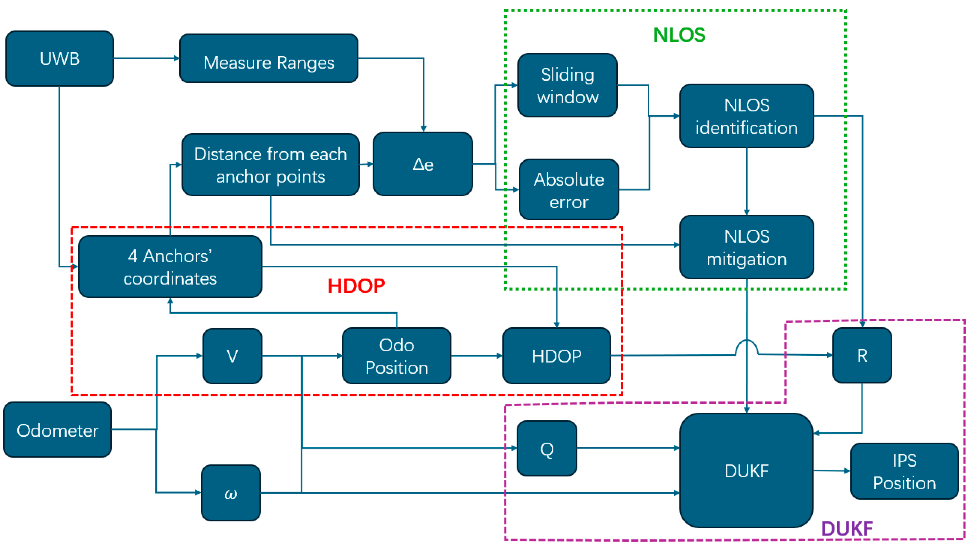
  • Propose a DUKF fusion method that dynamically adjusts the UKF based on NLOS, HDOP, and robot motion states to achieve more accurate localisation.
  • Compared with previous studies, the experimental environment designed in this paper is harsher for the fusion system of UWB and the odometer, which is better for verifying the accuracy and robustness of the system.
The organisation of this paper is as follows: the second part introduces algorithms, encompassing fusion algorithms and tightly coupled frameworks; the third part presents experimental design and result analysis; the fourth part entails a discussion; and finally, there are conclusions of this paper along with future research plans.

2. Methods

Some studies have used simpler, loosely coupled algorithms for the fusion of UWB and other sensors, but such algorithms require each subsystem to compute the robot’s position independently [29]. In a strong NLOS environment, accurate positioning information becomes challenging due to limited LOS distance measurements from the UWB system. The accuracy of IPS based on loose coupling will also be significantly affected by inaccurate UWB positioning. Conversely, tightly coupled integration utilises raw measurement data from both subsystems as inputs and employs fusion algorithms to calculate the system’s coordinates and pose. Tightly coupled integration processes data early, improving complexity and accuracy compared to loose coupling. In complex environments, tight coupling accuracy is better than loose coupling [36]. The tight coupling algorithm adopted in this paper is shown in Figure 1 below.
The UWB system provides distance measurements from the robot to the four anchor points, while the wheeled odometer calculates information about the robot’s motion and position. The odometer position can be used to assist in calculating the HDOP value of the UWB system and the distance to the four UWB anchor points. Specifically, HDOP is a ratio factor that reflects the effect of the geometrical relationship between the position of the anchor point and the tag in the UWB system and its accuracy. The final positioning error is obtained by multiplying the base positioning error with the HDOP value. Ideally, the HDOP value is small, but if the HDOP value is large, it means that the UWB system is not well placed, which increases the error and reduces the accuracy. The distances calculated from the UWB ranging values and the odometer positions can be used to identify and mitigate the NLOS errors of the UWB. Finally, the DUKF algorithm proposed in this paper can obtain optimised positioning information. The algorithm illustrated in Figure 1 consists of three main parts: NLOS identification and mitigation, computation of HDOP values, and DUKF fusion of all data to output robot coordinates. These three parts are explained separately in the following.

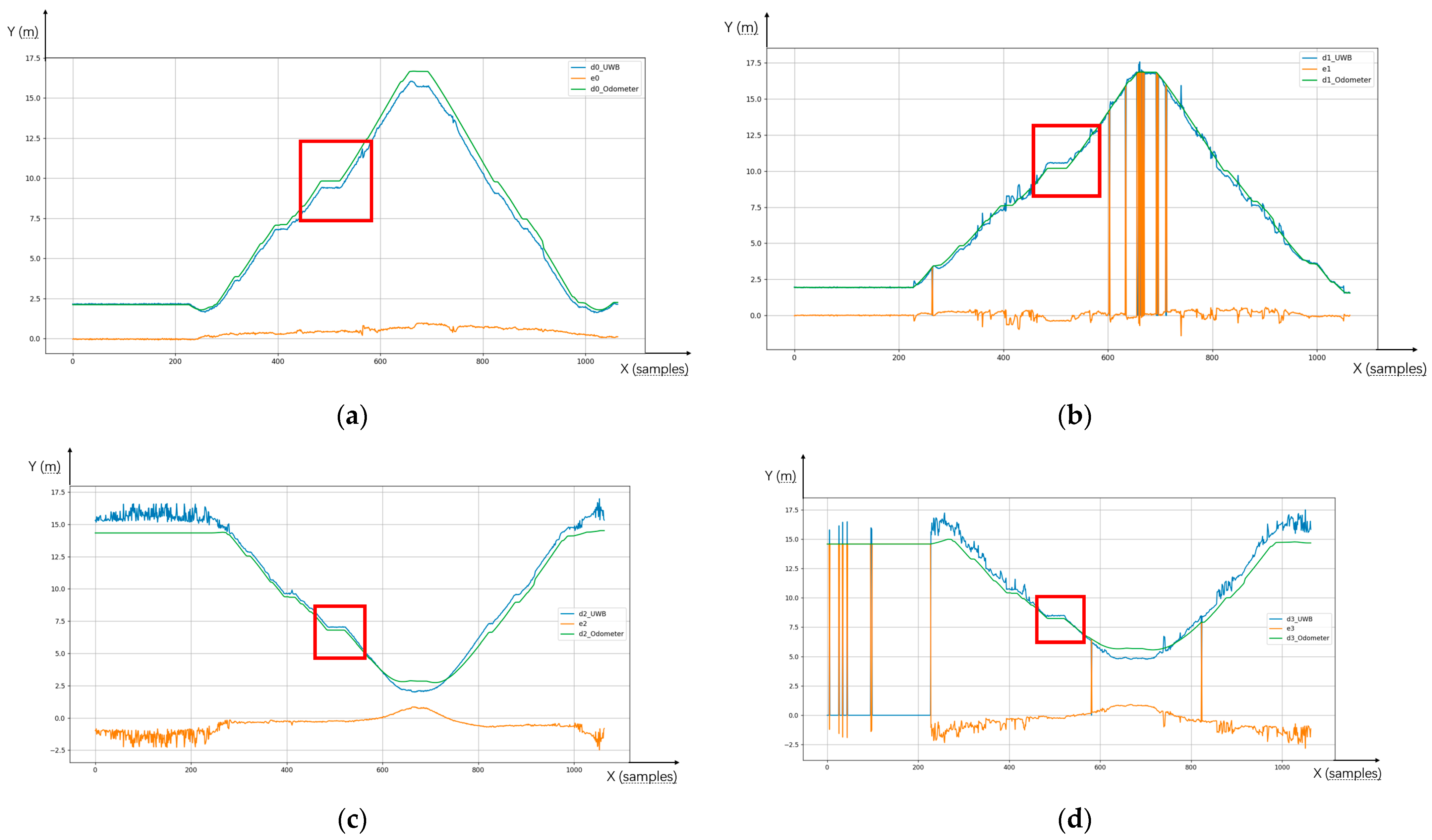
2.1. NLOS Identification and Mitigation

When UWB is affected by NLOS, a positive error in the corresponding distance measurement is introduced. Wheel odometry can provide high-frequency outputs of the robot’s speed and direction, which can be used to determine the robot’s position. Identification and mitigation of NLOS can be achieved by comparing the distance of the odometer coordinates to the UWB anchor point and the corresponding measured distance of the UWB.
abs ( Δ e ) =   abs ( d O d o m e t e r d U W B ) { < T h r e s h o l d 1     L O S T h r e s h o l d 1   N L O S
In Equation (1), the difference (Δe) between the distance between the odometry-provided position information and the fixed anchor points of UWB ( d O d o m e t e r ) and the UWB measured range ( d U W B ) can be used to identify NLOS. Ideally, Δe should be equal to zero, but cumulative errors in odometry cause Δe changes over time. Nevertheless, ranging errors caused by NLOS can be several tens of centimetres or even meters, Δe can still serve as an effective basis for identifying NLOS.
Relying solely on this method for NLOS identification is not accurate enough; therefore, we apply the sliding window algorithm proposed in previous research [38] to Δe. If sudden changes or outliers occur within Δe, it indicates that the current UWB distance measurement is affected by NLOS. When the window size is k , NLOS can be determined by Equation (2).
Var ( Δ e n k ,   Δ e n k + 1 Δ e n ) { < T h r e s h o l d 2     L O S T h r e s h o l d 2   N L O S
If the UWB range value at a particular time is identified as containing NLOS by two judgment conditions, then the range value is judged to have suffered from the effect of NLOS error. By combining these two criteria for judgment, NLOS can be identified more accurately. The impact of the NLOS error is much larger than the cumulative error of the odometer. Thereby, identified range values from an anchor point containing NLOS errors are replaced directly with distances between odometer positions and this anchor point. This method improves accuracy in updating measurement values using UKF.

2.2. HDOP

Similar to GPS, the accuracy of UWB systems is influenced by the distribution of anchor points and their geometric relationship with the tag. In this paper, which focuses on two-dimensional plane positioning using a wheeled robot, HDOP can be utilised to quantify measurement accuracy at specific locations.
If there are n fixed anchors in the UWB system, the anchor point coordinates are ( x i , y i ) i ∈ {0,1,2,…, n 1 }, while the tag coordinates are (x, y), with a distance of di between them. The unit line-of-sight vector (ai, bi) for anchor point i can be obtained from Equation (3) below.
a i = x i x d i ,   b i = y i y d i
H = [ a 0 b 0 a 1 b 1 a n 1 b n 1 ]
The unit line-of-sight vectors of all anchors can form the observation matrix H (Equations (4)), and the covariance matrix Q is represented by Equation (5). As H D O P is the horizontal component of the Q matrix, it can be expressed by Equation (6).
Q = ( H T H ) 1
H D O P = Q 11 + Q 22
In order to prevent UWB NLOS errors from affecting the accuracy of HDOP, the robot’s position calculated by the odometer is used instead of the tag position when calculating HDOP.

2.3. UKF

UKF is an extension of KF, mainly used to deal with nonlinear systems. Unlike EKF’s method of linearising nonlinear systems, UKF is an approximate nonlinear system based on the UT of Sigma points, avoiding complex Jacobian matrix calculations [39] and the errors introduced by linearisation. According to the literature [32], the accuracy of EKF can reach the first order of the Taylor series, while the accuracy of UKF can reach the third order of the Taylor series. The following equation describes the standard UKF calculation process.
Step 1: Set the initial value of UKF:
X ^ 0 = E ( X 0 )
P 0 = E [ ( X X 0 ) ( X X 0 ) T ]
The X ^ 0 is the initial state estimation vector, P 0 is the initial covariance matrix.
Step 2: Calculate Sigma points:
X k ( 0 ) = x ^ k
X k ( i ) = x ^ k + ( 1 ) i ( n + λ ) P k i   f o r   i = 1 , 2 , , 2 n
The corresponding weights are:
W 0 ( m ) = λ n + λ
W 0 ( c ) = λ n + λ + ( 1 α 2 + β )
W i ( m ) = W i ( c ) = 1 2 ( n + λ )   f o r   i = 1 , , 2 n
λ = α 2 ( n + κ ) n
where   n is the dimension of the state vector, α, β, and κ are used to adjust the distribution and weight of Sigma points.
Step 3: Sigma point propagation:
X k ( i ) = f ( X k 1 ( i ) , u k )
Sigma points spread through the state transition function 𝑓, u k is the control input.
Step 4: Predictions:
The predicted values of the state vector ( x ^ k ) and covariance matrix ( P k ) can be calculated using Sigma points:
x ^ k = i = 0 2 n w m ( i ) X k ( i )
P k = i = 0 2 n w c ( i ) [ X k ( i ) x ^ k ] [ X k ( i ) x ^ k ] T + Q
where w m ( i ) represents the weight of the mean, w c ( i ) represents the weight of covariance, and 𝑄 is the process noise covariance.
Step 5: Update:
Sigma points propagate through observational models.
Z k ( i ) = h ( X k ( i ) )
h is the observational model.
Calculate the prediction and covariance of the observations:
y ^ k = i = 0 2 n w m ( i ) Z k ( i )
S k = i = 0 2 n w c ( i ) [ Z k ( i ) y ^ k ] [ Z k ( i ) y ^ k ] T + R
R is the observed noise covariance.
Calculate the Kalman gain:
K k = P x y S k 1
P x y = i = 0 2 n w c ( i ) [ X k ( i ) x ^ k ] [ Z k ( i ) y ^ k ] T
Update state vector and covariance.
x ^ k = x ^ k + K k ( y k y ^ k )
P k = P k K k S k K k T
Following the iterative process described above, UKF can effectively handle systems with strong nonlinear characteristics. The parameters α, κ, β, Q, and R in the given equation play a crucial role in determining the performance of UKF. Among these parameters, α controls the diffusion level of Sigma points and is typically assigned a small value such as 1 × 10 3 . κ is used to adjust the weight distribution of Sigma points and is usually set to 0 in practical experiments. Additionally, a parameter β influences the characteristics of state distribution when calculating the mean weight; for Gaussian distributed states, β is commonly set to 2.
In the fusion IPS of the UWB and odometer, Q and R affect the degree of dependence of the fusion system on the two subsystems. Especially in practical applications, the two subsystems will change due to environmental factors or changes in the robot’s state. Setting Q and R to a fixed value will seriously affect the performance of UKF. In this paper, the Q and R of UKF were dynamically adjusted by considering the NLOS and HDOP values of UWB and the motion state of the robot.

3. Experimental Design and Results

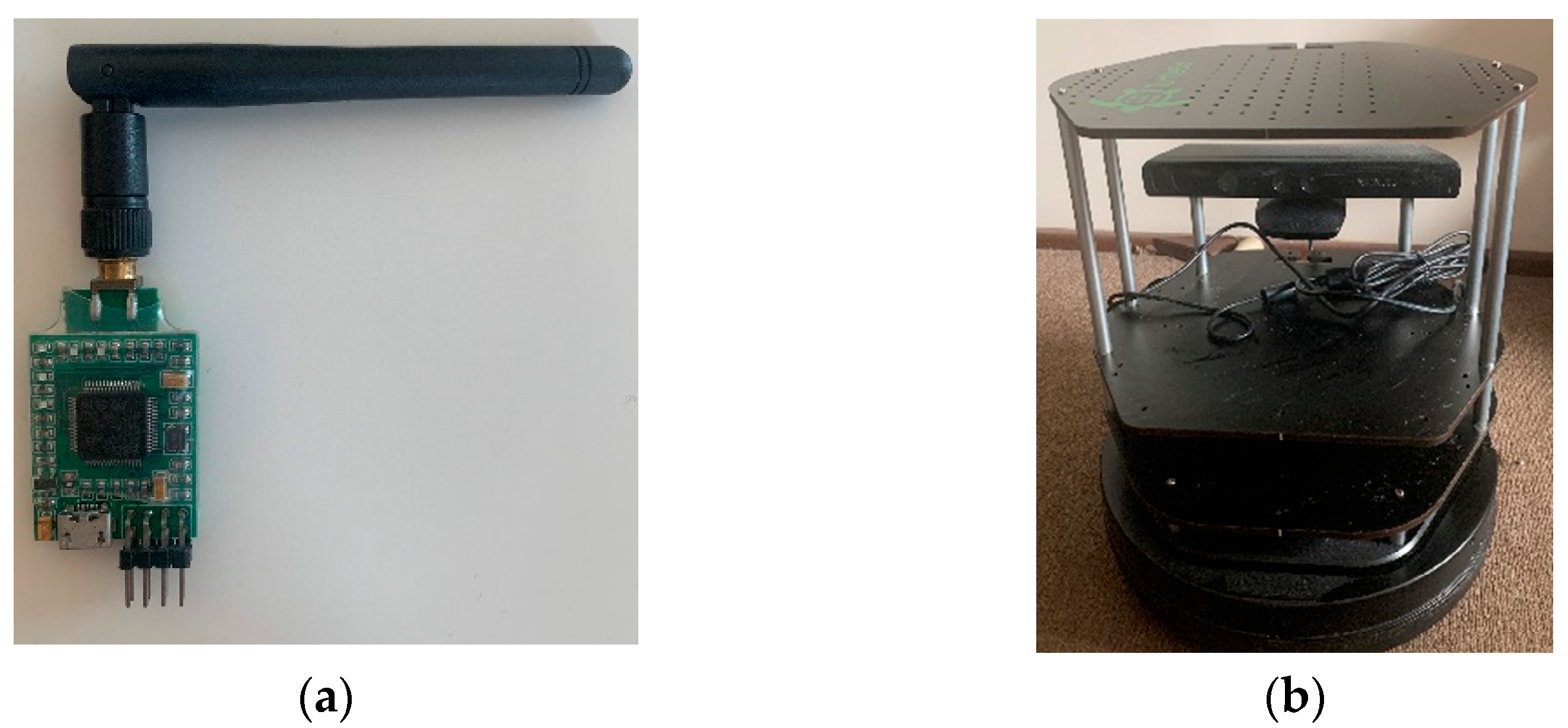
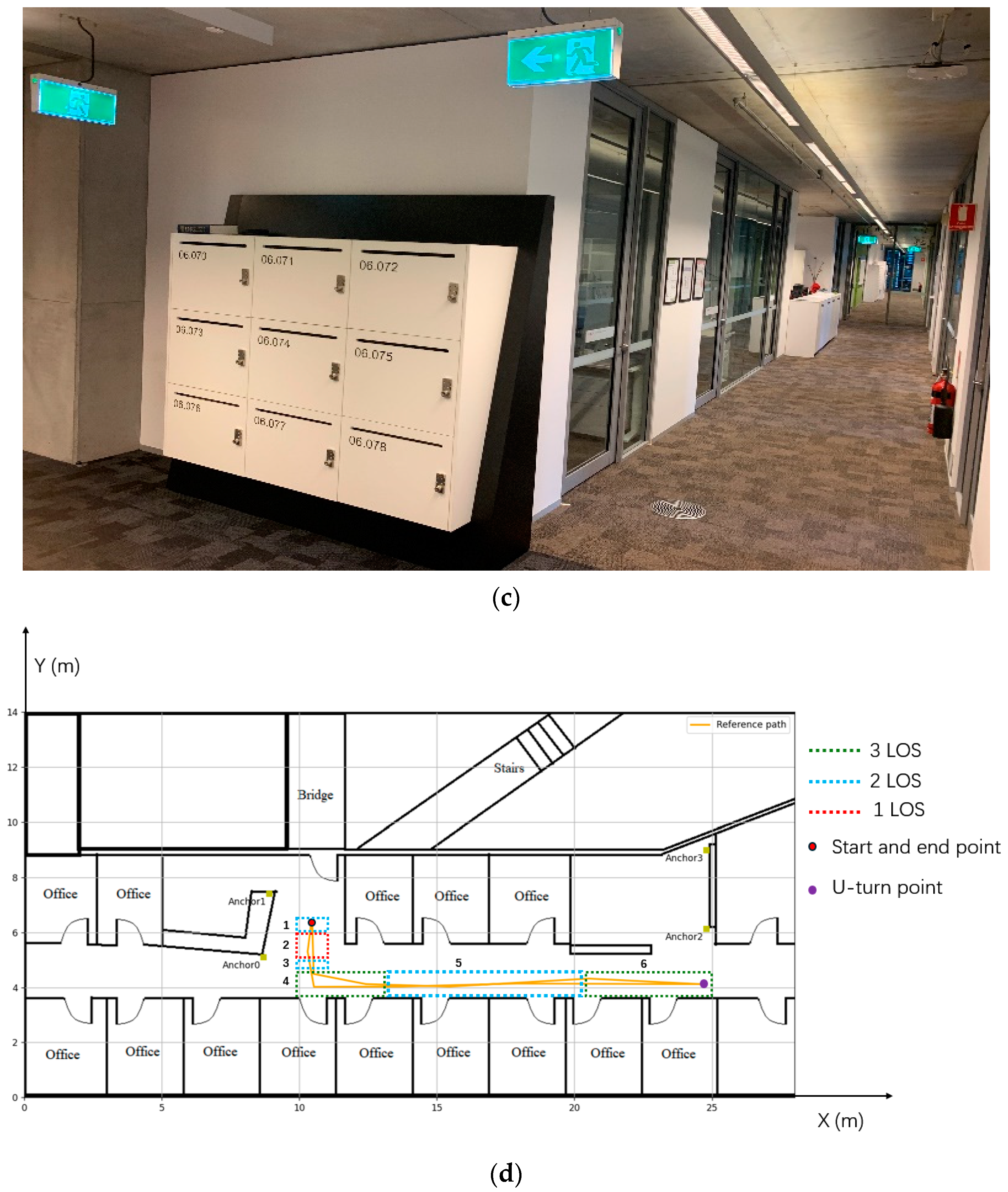
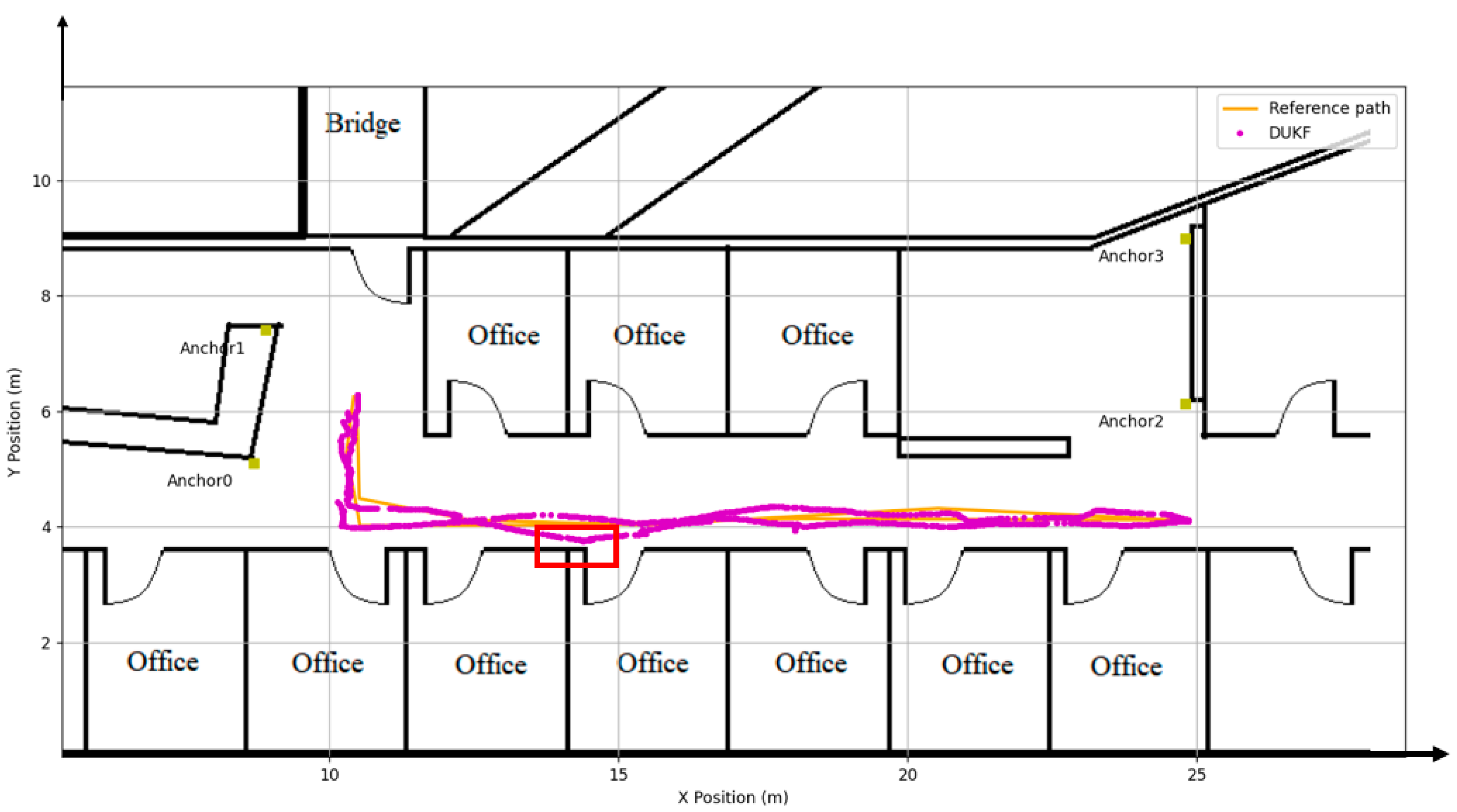
3.1. Experimental Equipment and Environment

The UWB experiment employs the DW1000 chips (Figure 2a) module from Decawave, which utilises the two-way ranging (TWR) method to measure the distance between the tag and anchor. Based on real measurements, it has been determined that this module operates at a sampling frequency of 3 Hz, providing a ranging accuracy within 10 cm under LOS conditions. The wheel odometry relies on turtlebot2’s built-in odometer (Figure 2b), operating at a sampling frequency of 20 Hz. Systematic and random errors are two primary sources of error in wheel odometry. Systematic errors arising from slight differences in wheel diameter and friction coefficient variations led to accumulated drift during positioning experiments. The random error resulted from wheel slippage and uneven surfaces during movement. The experimental trials were conducted on the sixth floor of UTS building 11, as shown in Figure 2c. The test site featured rough and even carpeting on the ground surface, effectively mitigating random errors associated with motion for the wheel odometry system. The UWB system is running on a Windows computer, and the odometer is running on Ubuntu on another computer. The two sets of data are time synchronised by the system time to validate the fusion algorithm proposed in this paper.
The experimental map and robot trajectory are depicted in Figure 2d. The four yellow boxes in this figure correspond to the positions of UWB anchors (Anchor 0, 1, 2, 3) with coordinates (8.7, 5.1), (8.91, 7.4), (24.8, 6.13), and (24.8, 8.99), and the height of the anchors are all 1.87 m. The orange solid line represents the reference path of the robot’s movement, and the red dots indicate its initial and final position. The robot starts from its initial position and moves to a U-turn point represented by a purple dot before returning to its starting point again. A UWB tag is installed on the robot; however, due to obstructions caused by walls during robot motion, some anchor measurements may experience NLOS errors. Within the region outlined by red dashed lines in the figure, the signal from Anchor 1 is obstructed by a cabinet, whereas walls block signals from Anchors 2 and 3. As such, only Anchor 0 remains within the LOS state in this area. Three LOS anchors exist at both corridor ends, indicated by green dashed lines. In the middle corridor enclosed within the blue dashed lines region, Anchors 0 and 2 remain within the LOS state while walls block signals from Anchors 1 and 3. The UWB system necessitates adaptive switching between environments with one, two, and three LOS anchors in this experimental setup. This environment significantly challenges the accuracy and stability of the proposed DUKF. The different LOS regions are numbered from left to right, as shown in Figure 2d. Table 1 below clearly shows which anchors are in LOS in different areas.

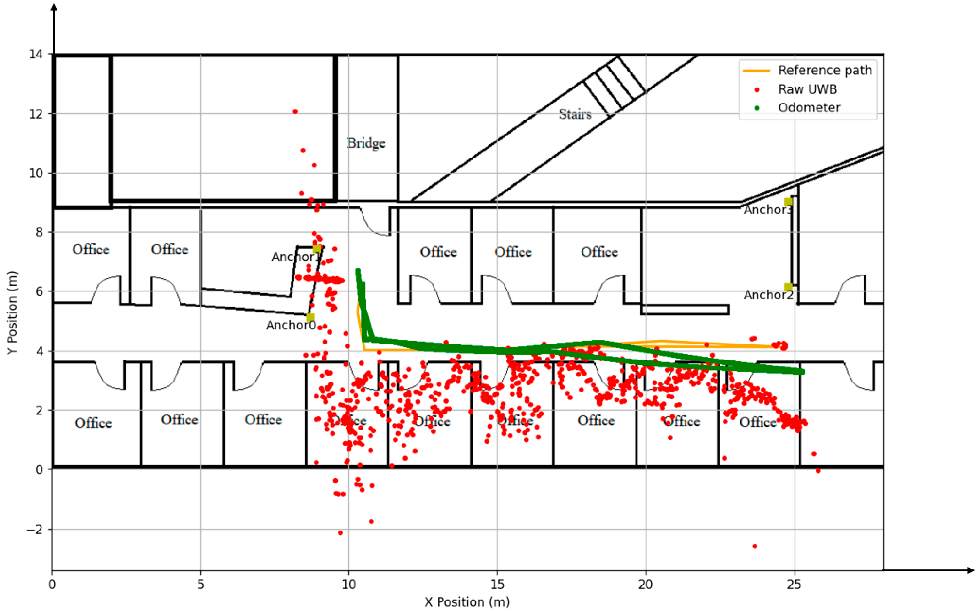
3.2. Experiment Results

Figure 3 below shows the trajectory plot using raw data from UWB and odometry. The red dots represent the coordinates of the tags calculated using the least squares method from the raw UWB data containing the NLOS errors. It shows the significant impact of NLOS errors on the UWB system’. Due to NLOS errors, the overall trajectory deviates from the reference path. The NLOS also increases measurement noise, resulting in more dispersed localisation points. In this scenario, the accuracy and precision of the UWB system are poor. The maximum error exceeds 6 m, and the RMSE surpasses 80 cm, making it difficult to meet indoor positioning requirements.
On the other hand, the green trajectory represents the original path plotted using odometry data. It can be observed that initially, at the early stages of motion, the green trajectory closely aligns with the reference path. However, as the distance travelled and the number of turns increase for odometry measurements, there is a gradual deviation from the reference path. This deviation reaches a maximum value of 1.093 m when it reaches the U-turn point. The average error and RMSE for odometry are over 20 cm. Although odometry also suffers from cumulative errors, it can still serve as an auxiliary means to identify which anchor point’s ranging value in the UWB system has been affected by NLOS errors, as shown in Figure 4.
The raw ranging values ( d n _ U W B , n = 0, 1, 2, 3) of the four UWB anchors are depicted in Figure 4 with four blue lines. It can be observed that the ranging value of Anchor 0 remains smooth and mostly unaffected by NLOS conditions. However, the remaining three anchors experience varying degrees of influence from NLOS during robot movement, leading to significant fluctuations in measured distances. Both Anchor 1 and Anchor 3 even lose data when the signal is blocked by a multi-wall. The data enclosed within the red box corresponds to situations where sudden pedestrian presence pauses robot movement temporarily. Furthermore, when the robot resumes its motion, NLOS occur as pedestrians pass through Anchors 0 and 1; this can also be observed from the fluctuating data in Figure 4.
The green line in the diagram represents the distance between the anchor point and the robot coordinates provided by the odometer ( d n _ O d o m e t e r , n = 0, 1, 2, 3). The orange line in the figure represents the difference ( e n ) between   d n _ O d o m e t e r and d n _ U W B . It can be observed from the graph that when UWB is affected by NLOS, e n exhibits a significant increase with pronounced fluctuations. By considering the absolute value of e n and employing the previously studied sliding window method, NLOS can be accurately identified. Under NLOS conditions, e n much smaller compared to NLOS errors. Therefore, this study mitigates NLOS effects by substituting d n _ U W B contains NLOS errors with corresponding d n _ O d o m e t e r values.
According to the robot’s position provided by the odometry, the HDOP value of the UWB system can be calculated. The UWB data after NLOS mitigation is used as observation input for UKF, with a noise covariance matrix R = diag[r0, r1, r2, r3]. According to the values of e n and HDOP dynamically adjusts R in UKF. The corresponding r n for range measurements with NLOS errors can be calculated by Equation (25).
r n = a b s ( e n ) v a r × H D O P
where var is the threshold in the sliding window identification NLOS algorithm, which changes according to different environments.
The state vector of the UKF system is X = [x,y,θ], where (x,y) represents the coordinates of the robot and θ is the heading angle. For this experiment, different Q values are set based on the robot’s motion state. The robot’s coordinates and heading angle remain constant when stationary, so the Q = diag [0, 0, 0]. During straight-line movement, the odometer coordinates are affected by more noise, and the heading angle is not affected as significantly. It is better to increase the values of x and y in Q and keep the values of θ at a small number, so set Q = diag [0.01, 0.01, 0.0001]. On the contrary, if the robot is in a turn, Q is set to diag [0.0001, 0.0001, 0.01]. By employing this fusion algorithm called DUKF, the fused trajectory of the system is shown in Figure 5.
The magenta line in Figure 5 represents the robot trajectory output through the DUKF algorithm, demonstrating its proximity to the reference path. Fusion with DUKF has significantly enhanced positioning accuracy compared to UWB and odometry, as evidenced by specific data in Table 2.
Figure 5 demonstrates the effective mitigation of harsh NLOS interference on the UWB system by the DUKF algorithm, resulting in optimised positioning accuracy and precision. A comparison with the odometer raw trajectory in Figure 3 shows a notable reduction in cumulative errors related to total mileage and direction of motion. The data presented in Table 2 indicates that under strong NLOS conditions, UWB positioning accuracy has degraded to unacceptable levels. The overall accuracy of the odometers exceeds expectations and can achieve an RMSE of around 0.3 m over long run times.
The DUKF algorithm significantly improved positioning accuracy, with an RMSE of 0.075 m and a mean error of 0.085 m, achieving the UWB system’s claim for a 10 cm positioning error under LOS conditions. The result demonstrated that the DUKF algorithm can achieve robust and highly accurate positioning in complex indoor environments.

4. Discussion

The data in Table 2 also reveals that DUKF still exhibits a maximum positioning error of 30 cm on the left side of the trajectory when the robot makes a right-angle turn to return to the ending point. In this area, there is only one valid LOS anchor point for UWB, and the odometry system also experiences a significant decrease in motion accuracy over long distances. Consequently, both subsystems’ observations and predictions contain substantial errors, indicating reduced accuracy in the final segment of the trajectory as the robot moves along the Y-axis during its return journey. The red boxes marked trajectory in Figure 5 represent a scenario explained in Figure 4 where the sudden appearance of pedestrians caused robot stoppage, and NLOS occurred for Anchors 0 and 1. Only Anchor2 remained in the LOS state for the UWB system during this time. It can be observed that the position result of DUKF was a brief deviation from the reference path at this moment, but as soon as the pedestrian obstruction disappeared, it gradually approached closer to the reference path again. Based on these two scenarios above, it can be concluded that even when applying the DUKF algorithm, at least one LOS UWB anchor point is necessary to ensure the system’s positioning accuracy.
Table 3 below summarises recent research on combining UWB with other sensors to form an IPS. The comparison reveals the advantages of the fusion system in this research.
In Table 3, it is evident that certain studies have achieved high positioning accuracy in UWB fusion systems, as demonstrated by references [37,41,42], all of which have accomplished positioning accuracy within 10 cm. However, these experiments were conducted primarily in LOS or mildly NLOS environments. For example, in literature [37], the NLOS of the UWB system is generated by the occlusion of the sparse plants in the greenhouse, and from the experimental results, it can also be seen that the system can achieve a positioning accuracy of about 15 cm when only using UWB, which also proves that UWB has a relatively mild effect on NLOS. Conversely, alternative sensors such as vision and LiDAR escalate hardware costs and fail to provide higher positioning accuracy comparable to UWB-only IPS. Consequently, some studies indicate decreased positioning accuracy when these sensors are integrated. For instance, references [40,45] reveal that a UWB system fused with visual sensors achieves an approximate positioning accuracy of 20 cm. Thus, the strength of this study lies in utilising cost-effective sensors to achieve centimetre-level positioning accuracy even under harsh NLOS conditions.

5. Conclusions

The present research proposes a tightly coupled architecture-based DUKF algorithm fusion of UWB and wheel odometry to form an IPS. This method offers the advantages of cost-effectiveness, high accuracy, and robustness without analysing UWB’s CIR characteristics or establishing error models, making it suitable for diverse indoor environments. The design of this validation experiment is highly rigorous, considering not only the NLOS state of some UWB anchors caused by wall obstructions but also interferences from a sudden human presence on both the odometry and UWB systems. The experimental scenarios meticulously consider real-life environmental factors, including a scenario with only one LOS anchor point. In this intricate and dynamic experimental setting, the proposed DUKF system achieved an impressive RMSE of only 0.075 m and an average error of 0.085 m, achieving stable robot localisation at centimetre-level accuracy. Future research plans will integrate sensors such as cameras or LiDAR into the system to enable mapping, obstacle recognition, collision avoidance, and path planning while concurrently maintaining precise positioning accuracy at the centimetre level.

Author Contributions

Conceptualisation, A.L. and J.W.; methodology, A.L. and J.W.; software, A.L.; validation, A.L.; formal analysis, A.L.; investigation, A.L.; resources, A.L.; data curation, A.L.; writing—original draft preparation, A.L.; writing—review and editing, A.L., J.W. and S.L.; visualisation, A.L.; supervision, J.W. and X.K.; project administration, A.L. and J.W.; funding acquisition, J.W. All authors have read and agreed to the published version of the manuscript.

Funding

This research received no external funding.

Data Availability Statement

The data can be shared up on request.

Conflicts of Interest

The authors declare no conflicts of interest.

References

  1. Poulose, A.; Eyobu, O.S.; Kim, M.; Han, D.S. Localization error analysis of indoor positioning system based on UWB measurements. In Proceedings of the 2019 Eleventh International Conference on Ubiquitous and Future Networks (ICUFN), Split, Croatia, 2–5 July 2019; pp. 84–88. [Google Scholar]
  2. Sun, W.; Xue, M.; Yu, H.; Tang, H.; Lin, A. Augmentation of fingerprints for indoor WiFi localization based on Gaussian process regression. IEEE Trans. Veh. Technol. 2018, 67, 10896–10905. [Google Scholar] [CrossRef]
  3. Jianyong, Z.; Haiyong, L.; Zili, C.; Zhaohui, L. RSSI based Bluetooth low energy indoor positioning. In Proceedings of the 2014 International Conference on Indoor Positioning and Indoor Navigation (IPIN), Busan, South Korea, 27–30 October 2014; pp. 526–533. [Google Scholar]
  4. Pu, Y.-C.; You, P.-C. Indoor positioning system based on BLE location fingerprinting with classification approach. Appl. Math. Model. 2018, 62, 654–663. [Google Scholar] [CrossRef]
  5. Kalbandhe, A.A.; Patil, S.C. Indoor positioning system using bluetooth low energy. In Proceedings of the 2016 International Conference on Computing, Analytics and Security Trends (CAST), Pune, India, 19–21 December 2016; pp. 451–455. [Google Scholar]
  6. Bai, N.; Tian, Y.; Liu, Y.; Yuan, Z.; Xiao, Z.; Zhou, J. A high-precision and low-cost IMU-based indoor pedestrian positioning technique. IEEE Sens. J. 2020, 20, 6716–6726. [Google Scholar] [CrossRef]
  7. Li, J.; Gao, W.; Wu, Y.; Liu, Y.; Shen, Y. High-quality indoor scene 3D reconstruction with RGB-D cameras: A brief review. Comput. Vis. Media 2022, 8, 369–393. [Google Scholar] [CrossRef]
  8. Karam, S.; Lehtola, V.; Vosselman, G. Strategies to integrate IMU and LiDAR SLAM for indoor mapping. ISPRS Ann. Photogramm. Remote Sens. Spat. Inf. Sci. 2020, 1, 223–230. [Google Scholar] [CrossRef]
  9. Chen, L.; Pei, L.; Kuusniemi, H.; Chen, Y.; Kröger, T.; Chen, R. Bayesian fusion for indoor positioning using bluetooth fingerprints. Wirel. Pers. Commun. 2013, 70, 1735–1745. [Google Scholar] [CrossRef]
  10. Bullmann, M.; Fetzer, T.; Ebner, F.; Ebner, M.; Deinzer, F.; Grzegorzek, M. Comparison of 2.4 GHz WiFi FTM-and RSSI-based indoor positioning methods in realistic scenarios. Sensors 2020, 20, 4515. [Google Scholar] [CrossRef]
  11. Song, X.; Fan, X.; Xiang, C.; Ye, Q.; Liu, L.; Wang, Z.; He, X.; Yang, N.; Fang, G. A novel convolutional neural network based indoor localization framework with WiFi fingerprinting. IEEE Access 2019, 7, 110698–110709. [Google Scholar] [CrossRef]
  12. Xie, T.; Jiang, H.; Zhao, X.; Zhang, C. A Wi-Fi-based wireless indoor position sensing system with multipath interference mitigation. Sensors 2019, 19, 3983. [Google Scholar] [CrossRef]
  13. Sun, H.; Chia, L.G.; Razul, S.G. Through-wall human sensing with WiFi passive radar. IEEE Trans. Aerosp. Electron. Syst. 2021, 57, 2135–2148. [Google Scholar] [CrossRef]
  14. Dong, M.; Qi, Y.; Wang, X.; Liu, Y. A non-line-of-sight mitigation method for indoor ultra-wideband localization with multiple walls. IEEE Trans. Ind. Inform. 2022, 19, 8183–8195. [Google Scholar] [CrossRef]
  15. Gezici, S.; Tian, Z.; Giannakis, G.B.; Kobayashi, H.; Molisch, A.F.; Poor, H.V.; Sahinoglu, Z. Localization via ultra-wideband radios: A look at positioning aspects for future sensor networks. IEEE Signal Process. Mag. 2005, 22, 70–84. [Google Scholar] [CrossRef]
  16. Wang, W.; Huang, J.; Cai, S.; Yang, J. Design and implementation of synchronization-free TDOA localization system based on UWB. Radioengineering 2019, 27, 320–330. [Google Scholar] [CrossRef]
  17. Gremigni, O.; Porcino, D. UWB ranging performance tests in different radio environments. In Proceedings of the London Communications Symposium, Toronto, ON, Canada, 5–8 September 2006. [Google Scholar]
  18. Yu, K.; Wen, K.; Li, Y.; Zhang, S.; Zhang, K. A novel NLOS mitigation algorithm for UWB localization in harsh indoor environments. IEEE Trans. Veh. Technol. 2018, 68, 686–699. [Google Scholar] [CrossRef]
  19. Kristensen, J.B.; Ginard, M.M.; Jensen, O.K.; Shen, M. Non-line-of-sight identification for UWB indoor positioning systems using support vector machines. In Proceedings of the 2019 IEEE MTT-S International Wireless Symposium (IWS), Guangzhou, China, 19–22 May 2019; pp. 1–3. [Google Scholar]
  20. Stahlke, M.; Kram, S.; Mutschler, C.; Mahr, T. NLOS detection using UWB channel impulse responses and convolutional neural networks. In Proceedings of the 2020 International Conference on Localization and GNSS (ICL-GNSS), Tampere, Finland, 2–4 June 2020; pp. 1–6. [Google Scholar]
  21. Jiang, C.; Shen, J.; Chen, S.; Chen, Y.; Liu, D.; Bo, Y. UWB NLOS/LOS classification using deep learning method. IEEE Commun. Lett. 2020, 24, 2226–2230. [Google Scholar] [CrossRef]
  22. Shaheen, F.; Verma, B.; Asafuddoula, M. Impact of automatic feature extraction in deep learning architecture. In Proceedings of the 2016 International Conference on Digital Image Computing: Techniques and Applications (DICTA), Gold Coast, Australia, 30 November–2 December 2016; pp. 1–8. [Google Scholar]
  23. Feigl, T.; Nowak, T.; Philippsen, M.; Edelhäußer, T.; Mutschler, C. Recurrent neural networks on drifting time-of-flight measurements. In Proceedings of the 2018 International Conference on Indoor Positioning and Indoor Navigation (IPIN), Nantes, France, 24–27 September 2018; pp. 206–212. [Google Scholar]
  24. Li, B.; Hao, Z.; Dang, X. An indoor location algorithm based on Kalman filter fusion of ultra-wide band and inertial measurement unit. AIP Adv. 2019, 9, 085210. [Google Scholar] [CrossRef]
  25. Liu, F.; Li, X.; Wang, J.; Zhang, J. An adaptive UWB/MEMS-IMU complementary kalman filter for indoor location in NLOS environment. Remote Sens. 2019, 11, 2628. [Google Scholar] [CrossRef]
  26. Peng, P.; Yu, C.; Xia, Q.; Zheng, Z.; Zhao, K.; Chen, W. An indoor positioning method based on UWB and visual fusion. Sensors 2022, 22, 1394. [Google Scholar] [CrossRef] [PubMed]
  27. Chen, Z.; Xu, A.; Sui, X.; Wang, C.; Wang, S.; Gao, J.; Shi, Z. Improved-UWB/LiDAR-SLAM Tightly Coupled Positioning System with NLOS Identification Using a LiDAR Point Cloud in GNSS-Denied Environments. Remote Sens. 2022, 14, 1380. [Google Scholar] [CrossRef]
  28. Chen, Z.; Xu, A.; Sui, X.; Hao, Y.; Zhang, C.; Shi, Z. NLOS Identification-and Correction-Focused Fusion of UWB and LiDAR-SLAM Based on Factor Graph Optimization for High-Precision Positioning with Reduced Drift. Remote Sens. 2022, 14, 4258. [Google Scholar] [CrossRef]
  29. Feng, D.; Wang, C.; He, C.; Zhuang, Y.; Xia, X.-G. Kalman-filter-based integration of IMU and UWB for high-accuracy indoor positioning and navigation. IEEE Internet Things J. 2020, 7, 3133–3146. [Google Scholar]
  30. Wang, C.; Xu, A.; Kuang, J.; Sui, X.; Hao, Y.; Niu, X. A high-accuracy indoor localization system and applications based on tightly coupled UWB/INS/floor map integration. IEEE Sens. J. 2021, 21, 18166–18177. [Google Scholar] [CrossRef]
  31. Yuan, D.; Zhang, J.; Wang, J.; Cui, X.; Liu, F.; Zhang, Y. Robustly adaptive EKF PDR/UWB integrated navigation based on additional heading constraint. Sensors 2021, 21, 4390. [Google Scholar] [CrossRef] [PubMed]
  32. Venkata Krishnaveni, B.; Reddy, S. Indoor Tracking by Adding IMU and UWB using Unscented Kalman Filter. Available online: https://www.researchsquare.com/article/rs-163258/v1 (accessed on 12 January 2024).
  33. Kolakowski, M. Comparison of Extended and Unscented Kalman Filters Performance in a Hybrid BLE-UWB Localization System. In Proceedings of the 2020 23rd International Microwave and Radar Conference (MIKON), Warsaw, Poland, 5–7 October 2020; pp. 122–126. [Google Scholar]
  34. Zhou, N.; Lau, L.; Bai, R.; Moore, T. Novel prior position determination approaches in particle filter for ultra wideband (UWB)-based indoor positioning. NAVIGATION J. Inst. Navig. 2021, 68, 277–292. [Google Scholar] [CrossRef]
  35. Hu, G.; Gao, B.; Zhong, Y.; Ni, L.; Gu, C. Robust unscented Kalman filtering with measurement error detection for tightly coupled INS/GNSS integration in hypersonic vehicle navigation. IEEE Access 2019, 7, 151409–151421. [Google Scholar] [CrossRef]
  36. Gao, B.; Hu, G.; Zhong, Y.; Zhu, X. Cubature Kalman filter with both adaptability and robustness for tightly-coupled GNSS/INS integration. IEEE Sens. J. 2021, 21, 14997–15011. [Google Scholar] [CrossRef]
  37. Long, Z.; Xiang, Y.; Lei, X.; Li, Y.; Hu, Z.; Dai, X. Integrated indoor positioning system of greenhouse robot based on UWB/IMU/ODOM/LIDAR. Sensors 2022, 22, 4819. [Google Scholar] [CrossRef]
  38. Liu, A.; Lin, S.; Wang, J.; Kong, X. A Succinct Method for Non-Line-of-Sight Mitigation for Ultra-Wideband Indoor Positioning System. Sensors 2022, 22, 8247. [Google Scholar] [CrossRef]
  39. Fu, J.; Fu, Y.; Xu, D. Application of an adaptive UKF in UWB indoor positioning. In Proceedings of the 2019 Chinese Automation Congress (CAC), Hangzhou, China, 22–24 November 2019; pp. 544–549. [Google Scholar]
  40. Hu, C.; Huang, P.; Wang, W. Tightly Coupled Visual-Inertial-UWB Indoor Localization System with Multiple Position-Unknown Anchors. IEEE Robot. Autom. Lett. 2023, 9, 351–358. [Google Scholar] [CrossRef]
  41. Zhang, H.; Zhang, Z.; Gao, N.; Xiao, Y.; Meng, Z.; Li, Z. Cost-effective wearable indoor localization and motion analysis via the integration of UWB and IMU. Sensors 2020, 20, 344. [Google Scholar] [CrossRef]
  42. Zheng, S.; Li, Z.; Liu, Y.; Zhang, H.; Zou, X. An optimization-based UWB-IMU fusion framework for UGV. IEEE Sens. J. 2022, 22, 4369–4377. [Google Scholar] [CrossRef]
  43. Feng, J.; Wang, L.; Li, J.; Xu, Y.; Bi, S.; Shen, T. Novel LiDAR-assisted UWB positioning compensation for indoor robot localization. In Proceedings of the 2021 International Conference on Advanced Mechatronic Systems (ICAMechS), Tokyo, Japan, 9–12 December 2021; pp. 215–219. [Google Scholar]
  44. Yang, X.; Wang, J.; Song, D.; Feng, B.; Ye, H. A novel NLOS error compensation method based IMU for UWB indoor positioning system. IEEE Sens. J. 2021, 21, 11203–11212. [Google Scholar] [CrossRef]
  45. Liu, F.; Zhang, J.; Wang, J.; Han, H.; Yang, D. An UWB/vision fusion scheme for determining pedestrians’ indoor location. Sensors 2020, 20, 1139. [Google Scholar] [CrossRef] [PubMed]
Figure 1. Flowchart of the proposed sensor fusion approach.
Electronics 13 01518 g001
Figure 2. Experiment design: (a) UWB; (b) turtlebot2; (c) experimental site; and (d) map and reference path.
Electronics 13 01518 g002aElectronics 13 01518 g002b
Figure 3. UWB and odometer raw trajectories.
Electronics 13 01518 g003
Figure 4. UWB ranging values (blue), the distance between the anchor point and odometer (green), the difference between the range and the distance (orange) and the robot is stopped by human interference (red box), (a) Anchor 0, (b) Anchor 1, (c) Anchor 2, (d) Anchor 3.
Electronics 13 01518 g004
Figure 5. Result of DUKF (magenta) and areas with pedestrian interference (red box).
Electronics 13 01518 g005
Table 1. LOS anchors in different areas.
Area123456
LOS Anchors0 and 100 and 10, 1, and 20 and 20, 2, and 3
Table 2. PositionError.
UWB-OnlyOdometerDUKF
Max (m)6.7081.0930.342
Mean (m)1.4840.2210.085
RMSE (m)0.8350.2960.075
Table 3. Comparison with other methods.
ReferenceSensorsHardware CostLOS/NLOSAccuracy (cm)
[40]Visual, Inertial, and UWBHighModerate NLOSRMSE: Over 20
[41]UWB, IMULowMild NLOSRMSE: 7.58
[42]UWB, IMULowLOSRMSE: 4.0
[37]UWB, IMU, Odometer, LiDARHighMild NLOSRMSE: 7–9
[43]LiDAR, UWBHighLOSRMSE: 14
[44]UWB, IMULowMild NLOSMean error: 12
[45]Visual, UWBHighLOSRMSE: 20
DUKFUWB, OdometerLowHarsh NLOSRMSE: 7.5
Disclaimer/Publisher’s Note: The statements, opinions and data contained in all publications are solely those of the individual author(s) and contributor(s) and not of MDPI and/or the editor(s). MDPI and/or the editor(s) disclaim responsibility for any injury to people or property resulting from any ideas, methods, instructions or products referred to in the content.

