Abstract
The voltage of the battery system is increased to increase the efficiency of the electric motor drive system. Additionally, the space vector pulse width modulation (SVPWM) technique is used to ensure high controllability. However, high-voltage and high-speed PWM switching controls for system efficiency generate high common mode voltage (CMV), and shaft voltage is induced in the bearing. This results in a shortened bearing life and potential damage. Therefore, this paper proposes a method to reduce the shaft voltage of the motor through a novel hybrid shield ring structure. It also analyzes how to improve the cooling performance of the motor using a shield ring. First, the parasitic capacitance inside the motor is analyzed. Then, the shaft voltage reduction technology is analyzed according to the material of the shield ring. Finally, experiments validate the proposed method. Additionally, the temperature characteristics of the main part of the motor are analyzed through an experiment in consideration of the shield ring.
1. Introduction
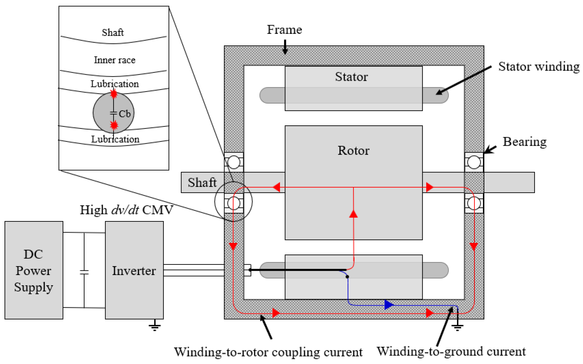
The development of electrification systems is actively underway worldwide due to recent environmental regulatory issues. In particular, various studies are being conducted on electric motor drive systems, battery systems, and power conversion systems, all of which are important components in the electrification system of electric vehicles (EVs) [1,2,3,4]. A stable battery system is important for achieving high efficiency and high speed in the traction motor used in the EV drive system, and the performance of a reliable inverter is necessary to ensure precise controllability [5,6,7]. Therefore, the voltage of the battery system is increased to enhance the efficiency of the electrification system [8,9,10,11]. It also utilizes insulated gate bipolar transistors (IGBTs) and silicon carbide (SiC), which can be switched at high speed to ensure precise controllability. The space vector pulse width modulation (SVPWM) technique is used for excellent voltage utilization [12,13,14]. However, increasing battery voltage and high-speed PWM switching control for system efficiency generate a high common mode voltage (CMV). Additionally, the CMV component generates shaft voltage through the parasitic capacitance of the motor. In the case of frame–shaft voltage, a path is formed as the circulating current flows to the ground [15,16]. As shown in Figure 1, the high PWM switching of the inverter creates a circulating current loop from the CMV through the windings to the stator, rotor, shaft, bearings, and motor housing. Therefore, as shaft voltage is induced in the bearing, parasitic current is generated, leading to insulation breakdown of the bearing lubricant. This results in electric discharge machining (EDM) inside the bearing. Consequently, this phenomenon leads to bearing faults. If the bearing is severely damaged, other serious motor faults may occur. To solve this problem, various studies are being conducted to reduce CMV and shaft voltage [17,18,19,20,21,22,23,24,25,26].
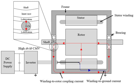
Figure 1.
Overview of motor drive systems.
In [18], a high-performance PWM algorithm to reduce CMV was proposed. Typically, the output of a three-phase PWM-controlled inverter, composed of power elements, exhibits numerous harmonic components due to switching, unlike the ideal three-phase sine wave. If the inverter’s voltage output is a symmetrical sinusoidal signal, CMV will be zero. However, because the three-phase PWM inverter uses a pulse waveform, the vector sum of the three-phase voltages does not become zero. This method has the advantage of reducing CMV and motor leakage current through the inverter’s high-performance PWM algorithm.
However, it has the disadvantage of placing a burden on the inverter processor during the processing process.
In [19], the shaft voltage that causes electrical and mechanical faults of the motor also shows various aspects depending on the bearing capacitance. In general, bearing capacitance varies depending on the type of bearing, the gap between the inner and outer rings of the bearing, the gap between bearing balls and races, the size of bearing balls, and the type of lubricant. This also has various effects on the shaft voltage, so it is important to also consider bearing capacitance analysis. In [20], the deterioration of bearing performance due to discharge bearing current is presented. As the shaft voltage is induced into the bearing, the insulation of the bearing is destroyed and current flows, resulting in a discharge bearing current. Discharge bearing current appears in various ways depending on the direction, size, and frequency of the current, which varies depending on the motor structure, operating conditions, bearing condition, etc. Research on discharge bearing current is also necessary because discharge bearing current can cause corrosion and damage to bearings, resulting in serious faults in the motor.
In [21], an experimental analysis of shaft voltage was studied, focusing on the variables of the inverter and motor of EVs by applying ceramic bearings. Additionally, switching frequency, oil temperature, rotational speed, and torque are used as variables for trend analysis. The shaft voltage trend of motors with ceramics is different from that of motors with steel bearings. As a result, it can be seen that although the shaft voltage is reduced by using ceramic, it is not completely reduced.
In [22], a method to reduce CMV and shaft voltage using the carrier phase shift of SVPWM was proposed. This method has the advantage of reducing CMV and shaft voltage by utilizing the inverter’s driving software algorithm without requiring a separate device to be installed on the motor. However, it has the disadvantage of placing a burden on the inverter’s processor during processing. In [23], a method of reducing shaft voltage was proposed by attaching a shaft grounding ring to the shaft of an electric motor. However, the shaft grounding ring requires periodic maintenance. Additionally, there is a disadvantage in that the conductive microfiber wears out and the shaft voltage reduction rate decreases. In [24], motor design was performed to reduce shaft voltage. The stator winding part was designed based on parasitic capacitance analysis according to the shape of the motor’s interior. Winding-to-stator parasitic capacitance (Cws) is confirmed to not affect shaft voltage. On the other hand, stator-to-rotor parasitic capacitance (Csr) and winding-to-rotor parasitic capacitance (Cwr) affect shaft voltage. Since Csr depends on the length of the air gap, it also affects the torque characteristics. However, the effect of Cwr on the torque characteristics is minimal, and it is confirmed that the effect of shaft voltage changes depending on the arrangement of the winding. As a result, the shaft voltage reduced without the need for a separate device. However, the reduction rate of shaft voltage is not very high. Additionally, when considering the manufacturability and mass production of the motor, there is a disadvantage in that constraints arise during design. Therefore, it is important to find a way to reduce shaft voltage while minimizing changes to the motor’s structure. In [25], a hybrid selective harmonic elimination pulse width modulation (SHEPWM) scheme for reducing CMV in three-level neutral-point-clamped inverter-based induction motor drives is proposed. The advantage of this method is that it eliminates low harmonics of the output line voltage, thereby reducing CMV. However, there is a disadvantage in that it places a burden on the inverter’s processor due to complex calculations. In [26], model predictive control methods were proposed to reduce the CMV of a three-phase voltage source inverter. The proposed method demonstrates excellent fast transient response performance in reducing CMV compared to existing model predictive control methods. However, because the cost function is calculated every sampling period, it places a burden on the processor of the inverter.
In this paper, a method to reduce the shaft voltage of an interior permanent magnet synchronous motor (IPMSM) is proposed through a new hybrid shielding structure. Additionally, we propose a structure that enhances the cooling performance of the motor through a hybrid shield ring. The cooling aspect of an electric motor system is crucial as it directly impacts efficiency. Hence, various studies are being conducted to improve the cooling performance of motors [27,28]. In [27], methods for improving the cooling performance of large-capacity open motors were studied. Cooling performance was checked using the fan inside the motor. Additionally, cooling performance improved by changing the fan structure. In [28], a new hollow shaft oil injection cooling structure of IPMSM for electric vehicles was proposed. In particular, the Taguchi method was used to analyze the effect of the oil injection cooling structure on the average temperature of the winding and the difference in injection flow rate at both ends of the motor. This optimization of the cooling structure has improved the cooling performance of the motor.
The contributions of this paper can be summarized as follows:
- (a)
- A method of reducing shaft voltage was proposed using a novel structural shield ring.
- (b)
- The proposed technology was verified through experiments. Additionally, a structure that improved the cooling performance of the motor through a shield ring was proposed.
This paper consists of the following sections: Section 2 explains the shaft voltage considering the parasitic capacitance inside the IPMSM. Section 3 proposes shaft voltage reduction technology depending on the shield ring material. Section 4 verifies the effectiveness of the proposed method through experimental settings and experiments. Additionally, considering the shield ring, the temperature characteristics of the main part of the IPMSM are analyzed through experiments.
2. Parasitic Capacitance Analysis and Shaft Voltage of IPMSM
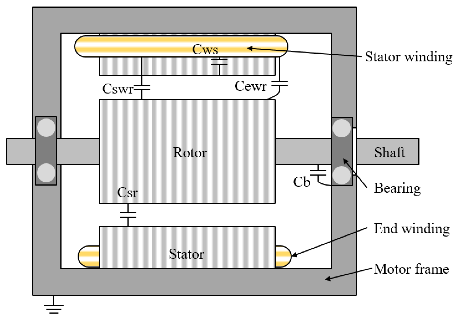
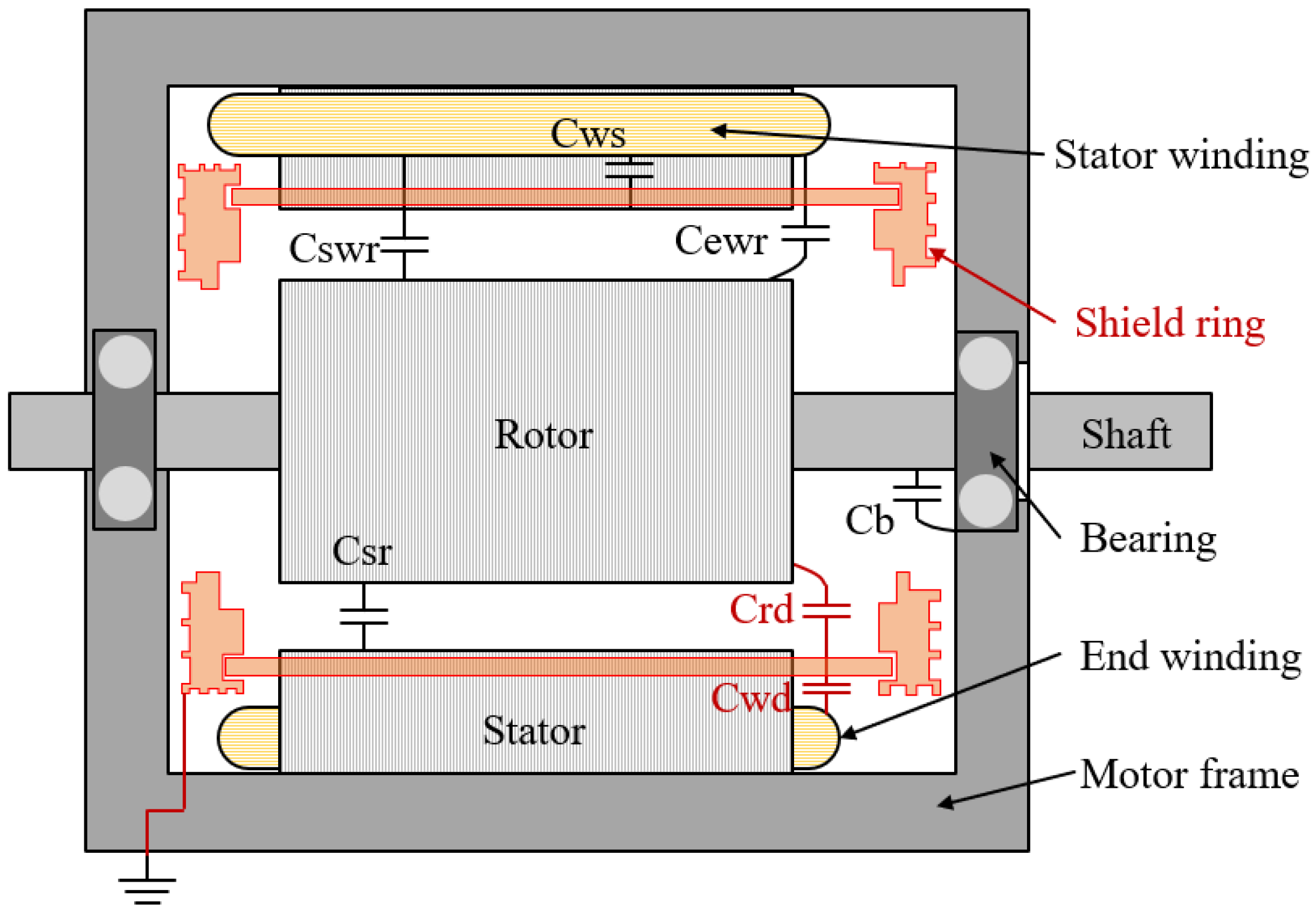
This section describes the parasitic capacitance and shaft voltage equivalent circuit of IPMSM. CMV generates shaft voltage. Figure 2 shows the parasitic capacitance of IPMSM. This parasitic capacitance causes bearing current to flow.
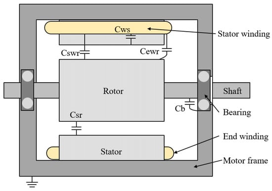
Figure 2.
Configuring parasitic capacitance for IPMSM.
Parasitic capacitances that typically affect shaft voltage include stator-to-rotor parasitic capacitance (Csr), bearing parasitic capacitance (Cbn), and winding-to-rotor parasitic capacitance (Cwr). Csr is the capacitance existing between the stator and the rotor. If the slot opening of the stator is not considered, the stator and rotor can be assumed to have concentric cylindrical capacitance, as shown in Figure 3a. Therefore, the value varies depending on the length of the air gap between the stator and rotor.
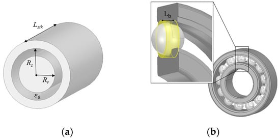
Figure 3.
Detailed configuration of IPMSM. (a) Configuration of the stator and the rotor; (b) detailed structure of bearing.
Csr can be calculated as
where is the permittivity of air, is the stack length of the stator, is the stator inner radius, and is the rotor outer radius.
The mechanical structure of a bearing consists of an inner race, an outer race, and a ball. Additionally, lubrication is applied inside the bearing for the rotation of the balls. Cbn occurs between the inner race, outer race, and ball. As the rotor rotates, the bearing raceways and balls randomly come into contact with each other. Because of this, when contact occurs, a component of resistance exists. There are various types of bearings, but deep groove ball bearings were applied in this study. As shown in Figure 3b, because the shape of the cylinder is complex, the length of the cylinder is defined as rc/2 (Lb). Therefore, the size of Cbn changes depending on the size, shape, and material of the ball in the bearing, the characteristics of the lubricant, and the thickness of the lubricant. Additionally, when high-frequency current is induced by shaft voltage, a large current flows through the bearing. As a result, the temperature of the bearing increases, the lubricant layer becomes thinner, or the lubricant leaks out, changing the electric field characteristics of the bearing. As a result, the magnitude of the shaft voltage is large, and the life of the bearing is shortened [29].
Cbn can be calculated as
where is number of balls inside bearing, is the permittivity of lubricant, is the radius of clearance with ball, and is the radius of the ball of bearing.
Additionally, Cwr is composed of stator winding-to-rotor (Cswr) and end winding-to-rotor (Cewr), as shown in Figure 2. Therefore, Cswr can be calculated as Equation (3), and Cewr can be calculated as Equation (4). In conclusion, Cwr is calculated by adding Cswr and Cewr.
where is the width of the slot opening, is the thickness of the end winding from the stator, and is the radius of the stator and end windings.
As shown in Figure 2, winding-to-stator parasitic capacitance (Cws) is the capacitance between the windings and the stator.
Cws can be calculated as
where is the number of the slots, is the coil height that lay on the stator, is the width of the stator teeth, is the width of the insulation paper, and is the permittivity of the insulation.
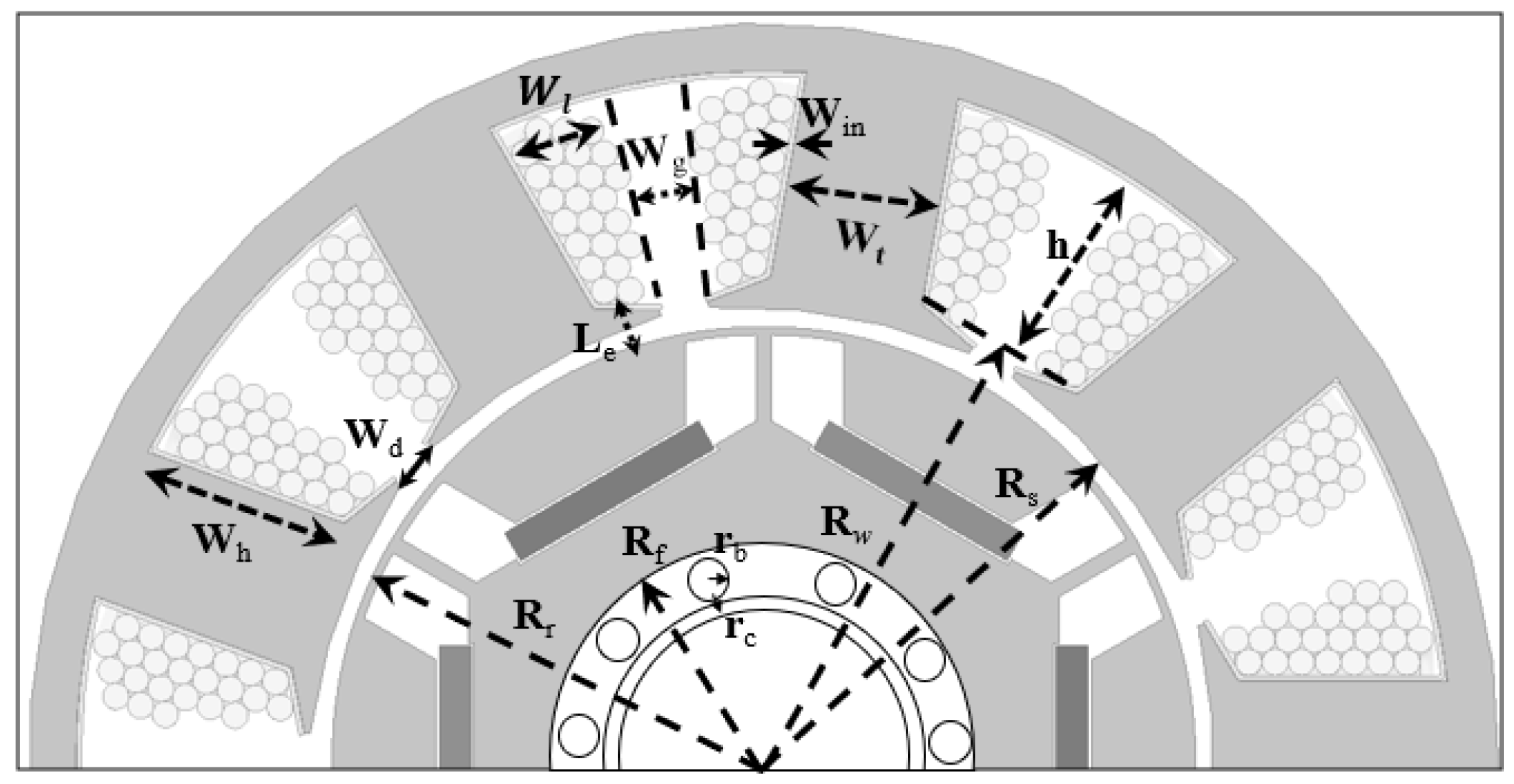
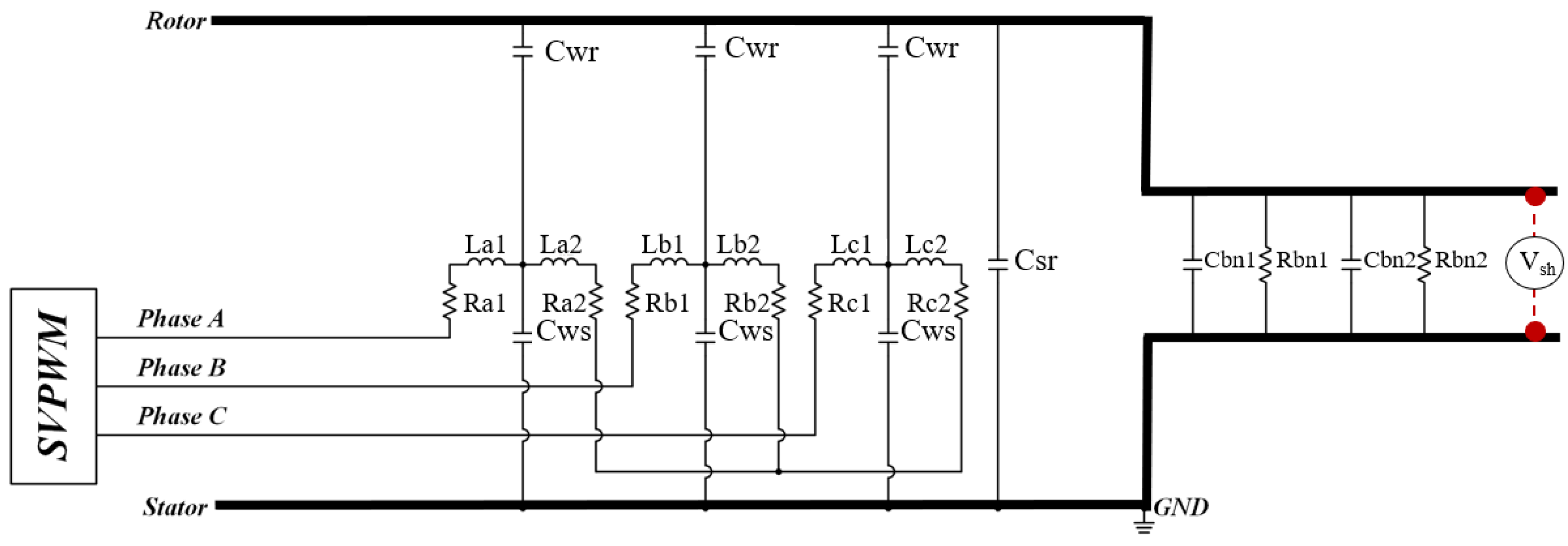
Figure 4 and Table 1 show the parameters for the IPMSM structure. Figure 5 shows the equivalent circuit considering parasitic capacitance. Here, La1 and La2 are A-phase windings, Lb1 and Lb2 are B-phase windings, and Lc1 and Lc2 are C-phase windings. Cbn1 and Rbn1 are parasitic capacitance and resistance of the motor’s front bearings. Cbn2 and Rbn2 are parasitic capacitance and resistance of the motor’s rear bearings.

Figure 4.
Structure and parameters of IPMSM.

Table 1.
Dimensions of IPMSM structure.
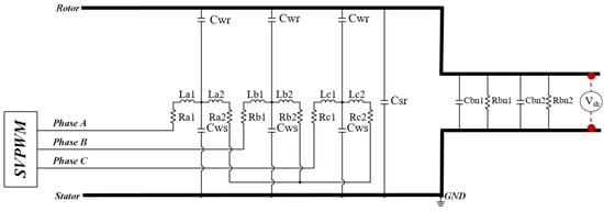
Figure 5.
Equivalent circuit for the parasitic capacitance of IPMSM (without shield ring).
The shaft voltage is defined as the voltage ratio between the input voltage and the bearing voltage, as shown in Equation (6). It is also determined by the parasitic capacitance of the motor. Therefore, the size of the shaft voltage is determined by the bearing voltage ratio (BVR).
where is the input voltage of the parasitic equivalent circuit, is the bearing voltage, and is the CMV.
3. Shaft Voltage Reduction Technique Using Shield Ring
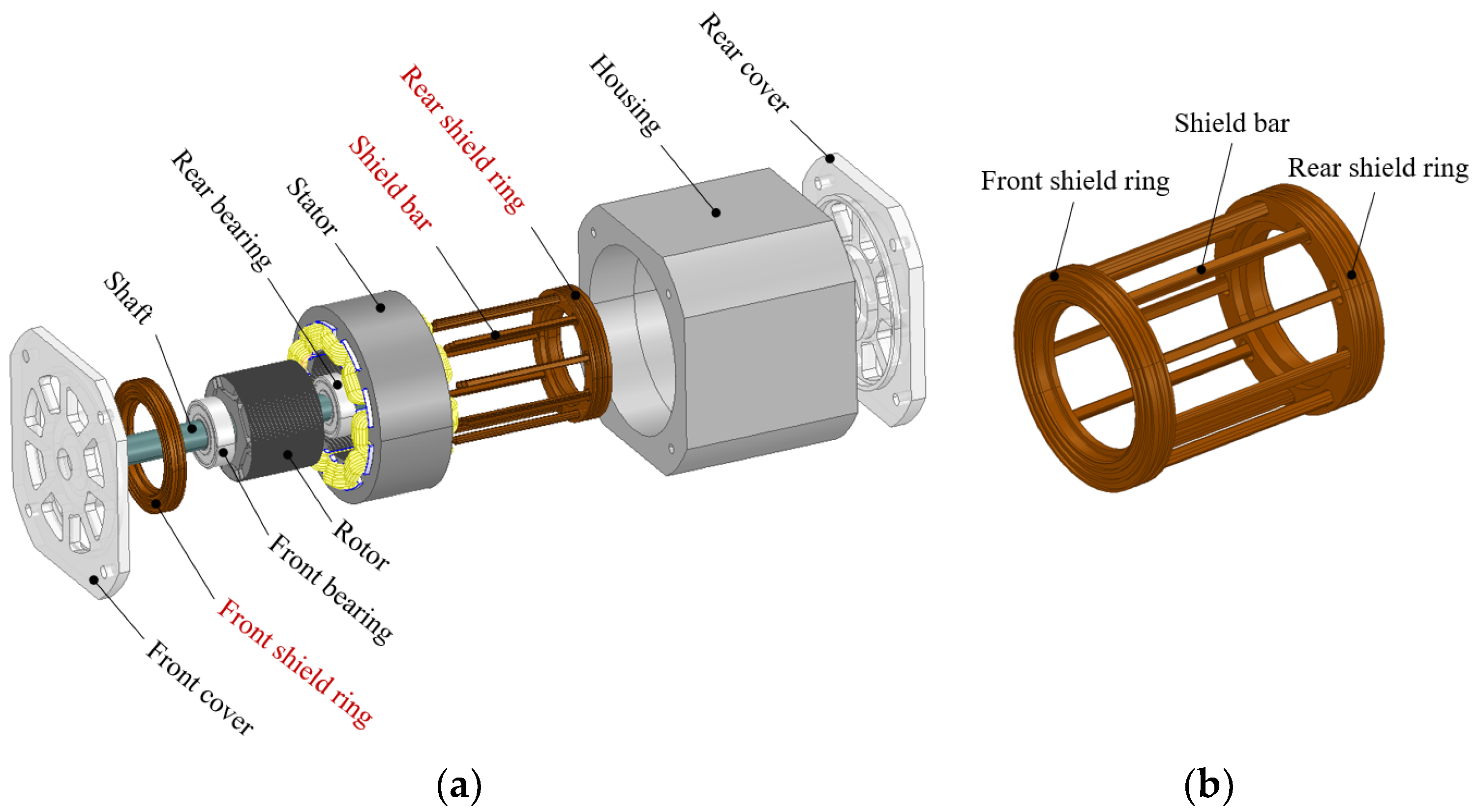
In this section, a shaft voltage reduction technique using a shield ring is explained. The Cwr parasitic capacitance component of IPMSM has the greatest influence on the shaft voltage. This study presents a technique to reduce shaft voltage by reducing Cwr. Figure 6a shows the overall structure of IPMSM with the shield ring considered. Therefore, we present a technique to reduce shaft voltage by reducing Cwr by applying a shield ring, as shown in Figure 6b. As shown in Figure 6b, the shield ring consists of a front shield ring, shield bar, and rear shield ring. Since the shield ring does not interfere with the rotor, it does not affect motor operation. In particular, the biggest advantage is that it is highly durable and does not require maintenance.

Figure 6.
Structure of IPMSM considering shield ring. (a) Overall structure; (b) shield ring.
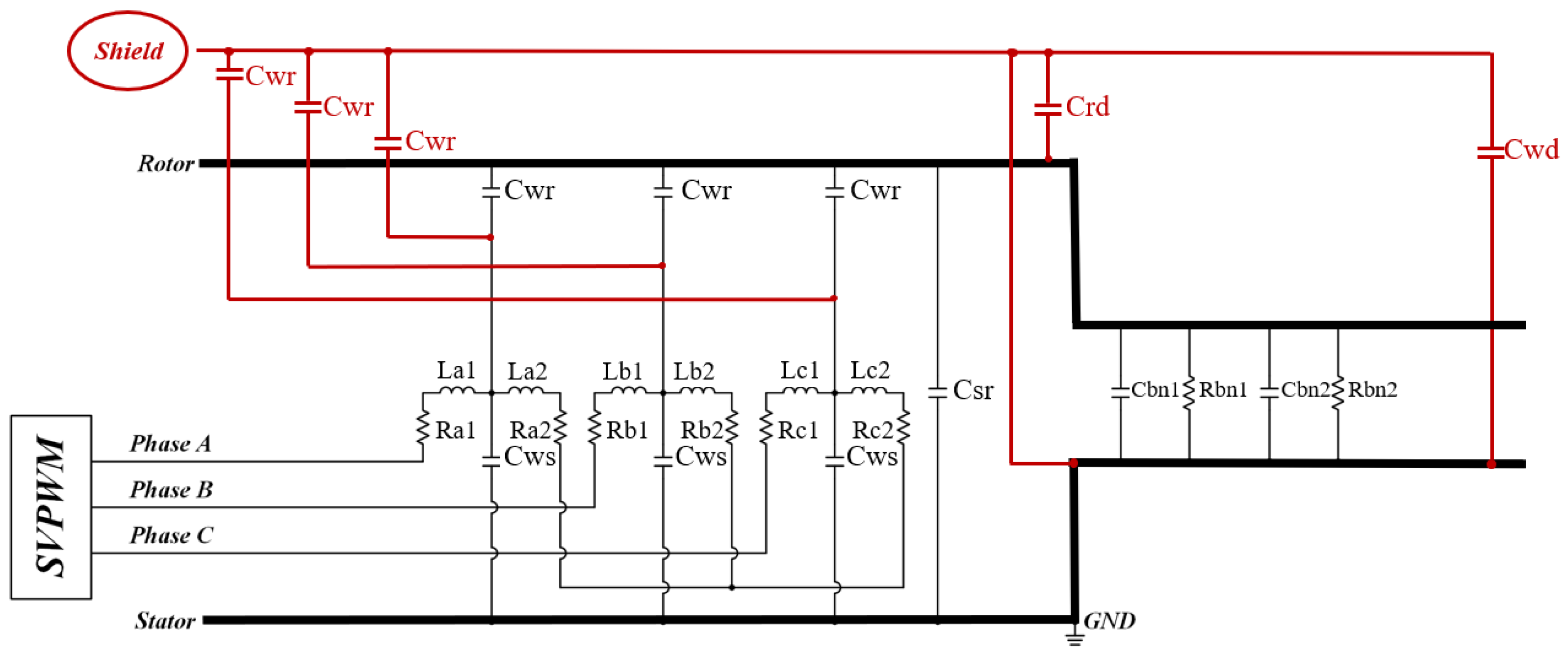
Figure 7 shows a cross-section of the IPMSM considering the shield ring. Figure 8 shows the equivalent circuit for the parasitic capacitance of IPMSM considering the shield ring. When a shield ring is applied, winding-to-shield parasitic capacitance (Cwd) and rotor-to-shield parasitic capacitance (Crd) are formed. Additionally, the shield ring is connected to the ground. As a result, the typical Cwr component that generates a large shaft voltage can be reduced through the shield ring. As a result, circulating current flows to the ground through the shield ring.
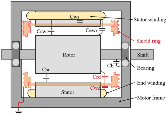
Figure 7.
Cross-section of IPMSM with shield ring.
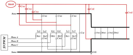
Figure 8.
Equivalent circuit for the parasitic capacitance of IPMSM (with shield ring).
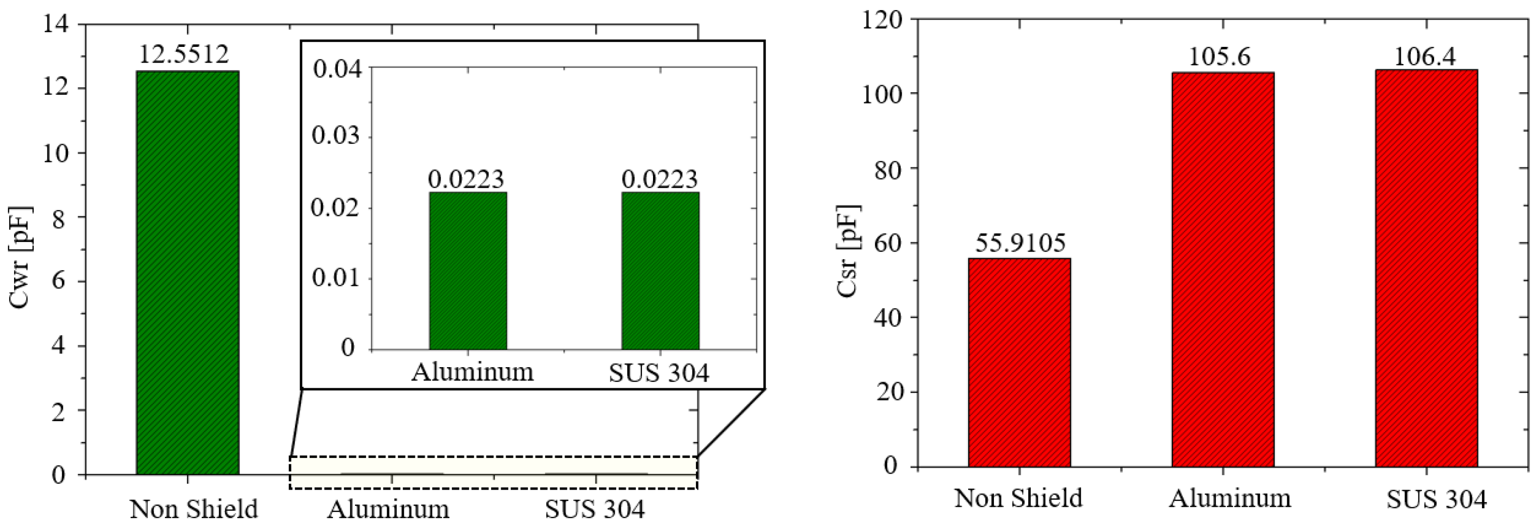
In particular, the shaft voltage reduction was analyzed using aluminum and stainless shield ring materials. The material properties are shown in Table 2. To calculate the parasitic capacitance of IPMSM, analysis was performed using Ansys 2021 R2 Q3D Extractor. As shown in Table 2, depending on the material, aluminum had the largest bulk conductivity, and SUS 304 had the smallest. Figure 9 shows the parasitic capacitance values depending on the material. When the shield ring was applied, Cwr was reduced by 99.8%. The reason was that there was almost no projected area between the winding and the rotor through the shield ring. Additionally, Csr was calculated to be a much larger value when the shield ring was applied.
Table 2.
Characteristics according to material.

Figure 9.
Parasitic capacitance depending on the material.
C can be calculated as [30]
where Q is the electric charge, V is the voltage, is the permittivity, and E is the electric field. According to Ohm’s law, current, I, and resistance, R, are expressed as
where J is the current density, σ is the conductivity, and G is the reciprocal of resistance and is the conductance. Subsequently, the capacitance, C, is inversely proportional to the conductivity, σ.
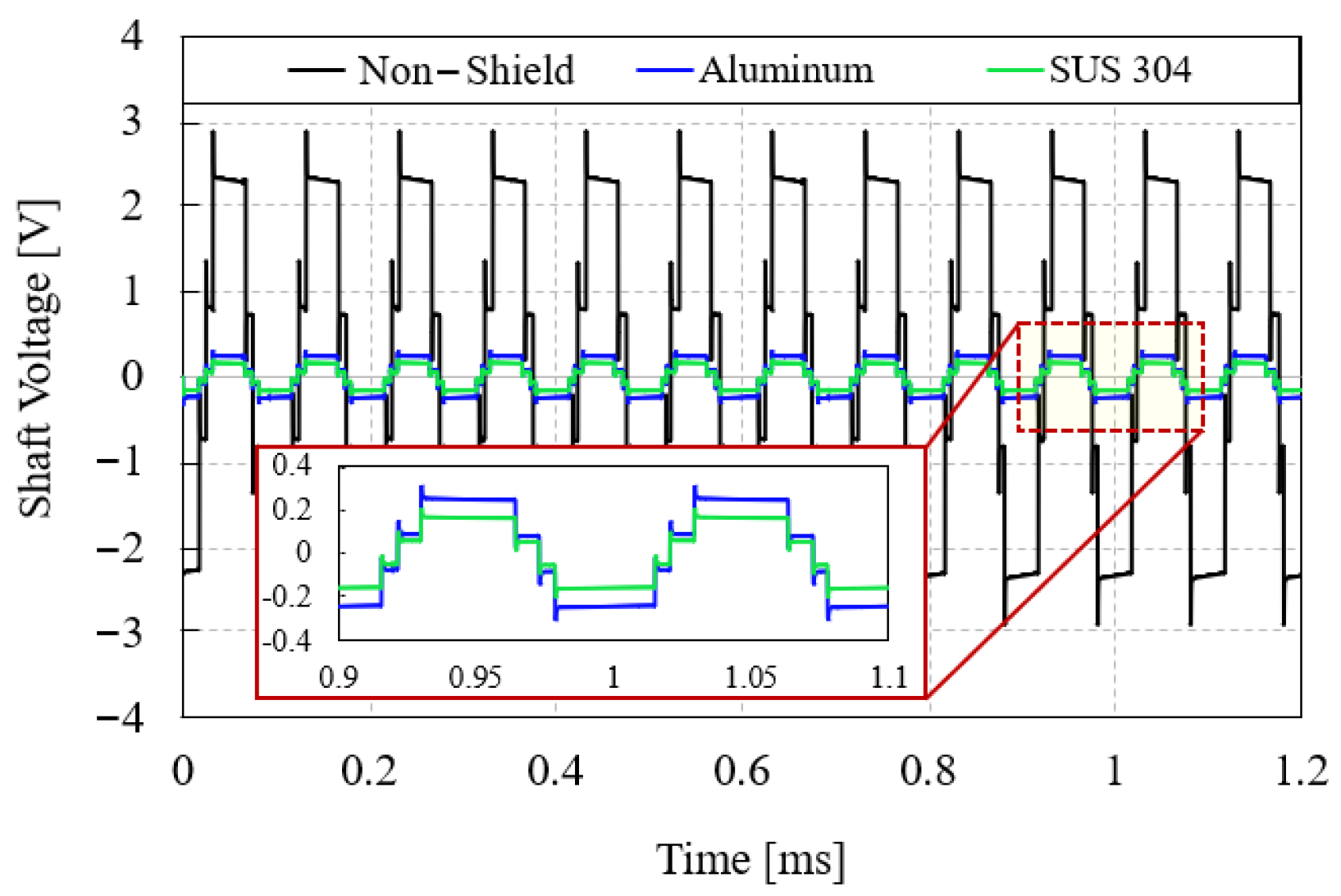
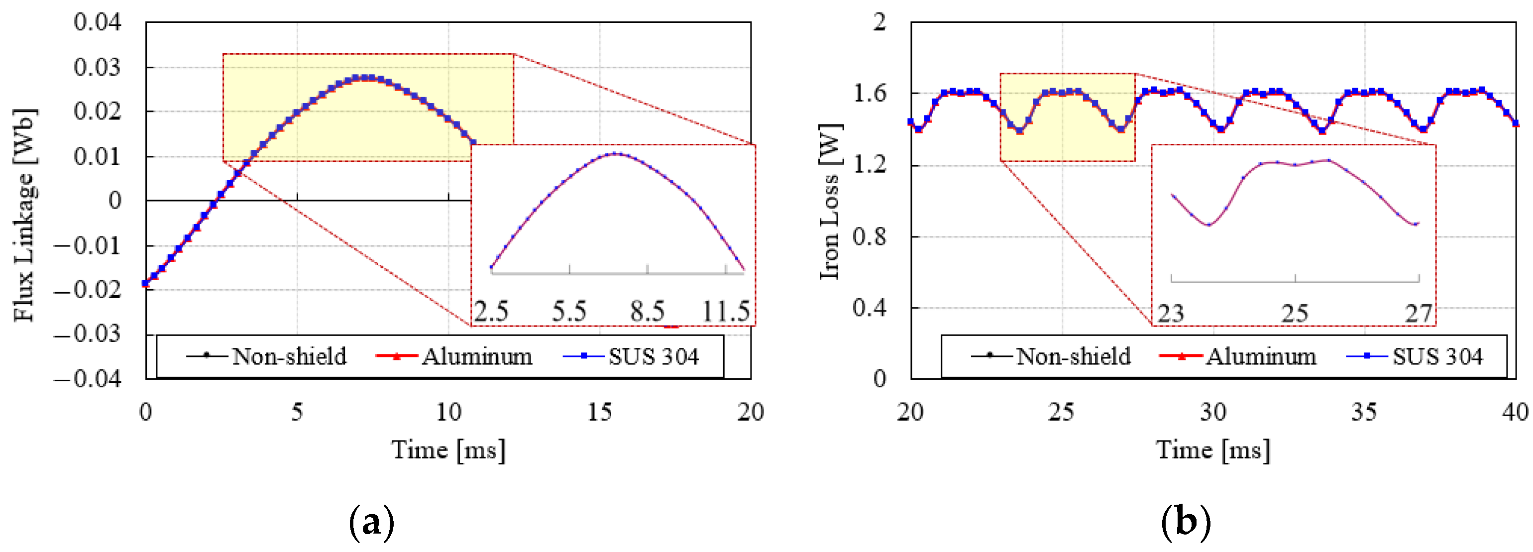
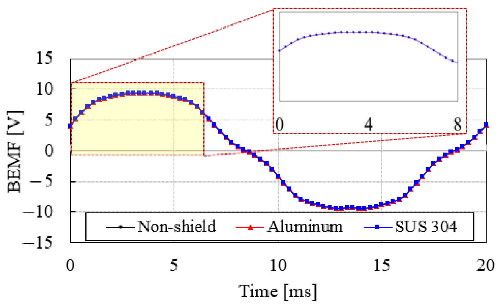
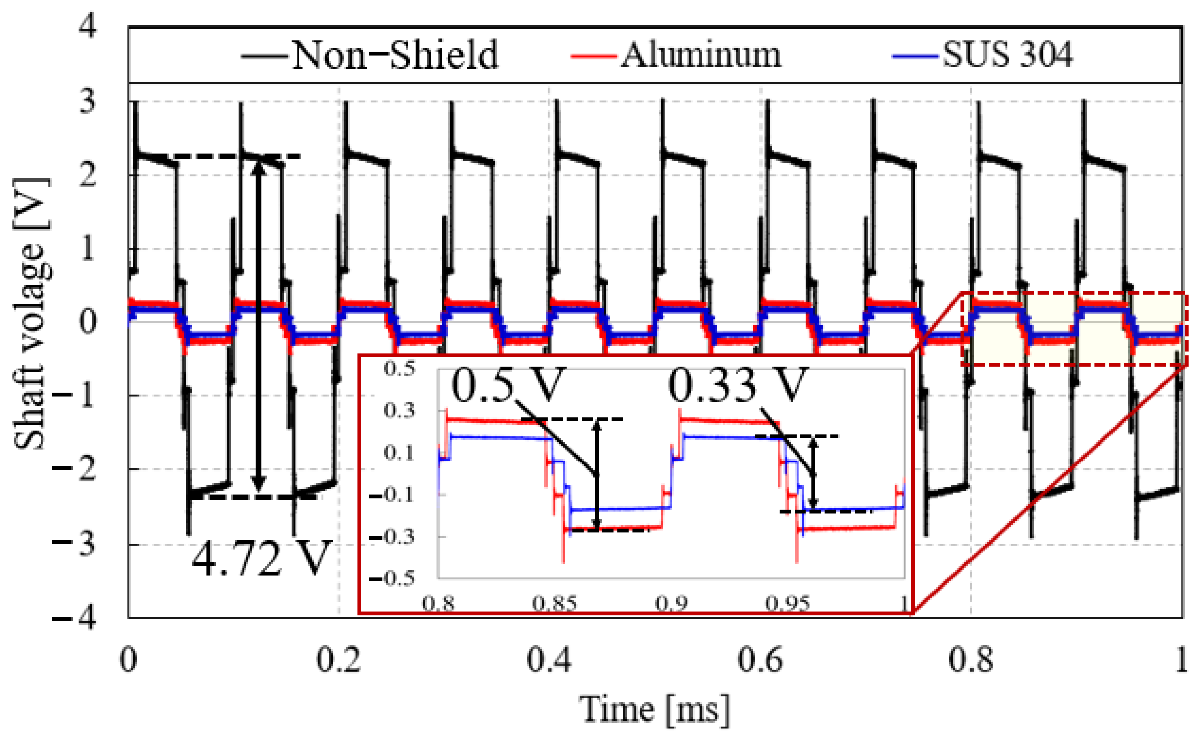
Therefore, the bulk conductivity of SUS 304 is the smallest, and the parasitic capacitance is the largest because electric charges are well collected. Figure 10 shows the results of the shaft voltage waveform simulation by shield ring material. Analysis was performed using MATLAB R2023a Simulink. In the simulation, the DC voltage was set to 48 V, and the analysis was performed at 1000 rpm. In the case of non-shield, the shaft voltage was calculated to be 4.68 V. In the case of the aluminum shielding ring, the shaft voltage was calculated to be 0.48 V. In the case of the SUS 304 shielding ring, the shaft voltage was calculated to be 0.3 V. As shown in Figure 10, when the SUS 304 product shield with the largest parasitic capacitance was applied, the shaft voltage was reduced by 93.5%. In conclusion, the smaller the conductivity, the greater the effect of reducing the shaft voltage of the motor. The finite element method (FEM) was used to analyze changes in properties when a shield ring was applied to IPMSM. In this study, analysis was conducted using Ansys 2021 R2 Maxwell. Simulations were performed at 1000 rpm and 10 Arms. The rated torque was 1.1 Nm. Simulation results according to the material are shown in Figure 11. As shown in Figure 11a, the flux linkage of all materials was the same at 0.0192 Wb. Therefore, there was no increase in flux linkage or leakage magnetic flux depending on the material. Figure 11b shows iron loss depending on the material. In the case of iron loss, the steady state results were analyzed without considering the transient state results in the simulation. As a result of the analysis, the iron loss of all materials was 1.54 W. Therefore, since the iron loss of IPMSM did not change, the characteristics did not change. Figure 12 shows the no-load back electromotive force waveform (BEMF) at 1000 rpm. All three cases were the same at 6.93 Vrms. Therefore, the electromagnetic field characteristics of the motor did not change depending on the materials.
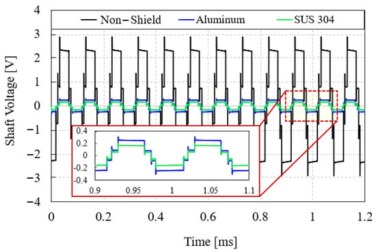
Figure 10.
Shaft voltage waveform according to material.
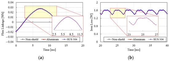
Figure 11.
FEM simulation results according to shield ring material. (a) Flux linkage; (b) iron loss.
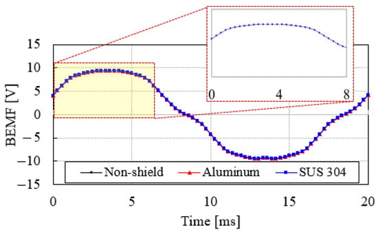
Figure 12.
BEMF waveform at 1000 rpm.
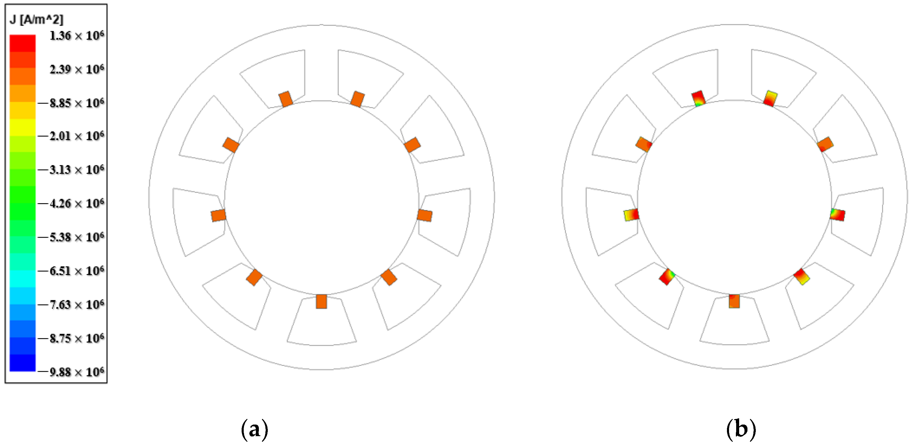
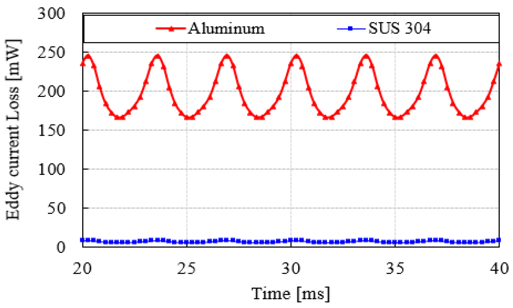
Figure 13 shows the current density distribution of the shield bar according to materials. As shown in Figure 13a, the current density of the shield bar made of SUS 304 is much smaller than that of the aluminum shield bar. The reason is that the eddy current loss flowing through the SUS 304 shield bar is 7.2 mW, and the eddy current loss flowing through the aluminum shield bar is 197.7 mW. In addition, very small eddy currents flow in all materials, so they have little effect on iron loss.
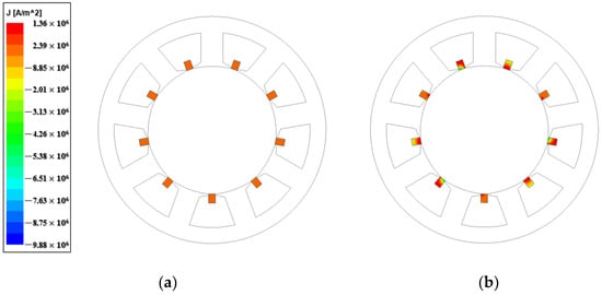
Figure 13.
Current density distribution of shield bar according to materials. (a) SUS 304; (b) aluminum.
4. Results and Discussion
In this section, the proposed method is verified through experiments. In addition, considering the shield ring, the temperature characteristics of the main part of the IPMSM are analyzed through experiments.
4.1. Experimental Setup
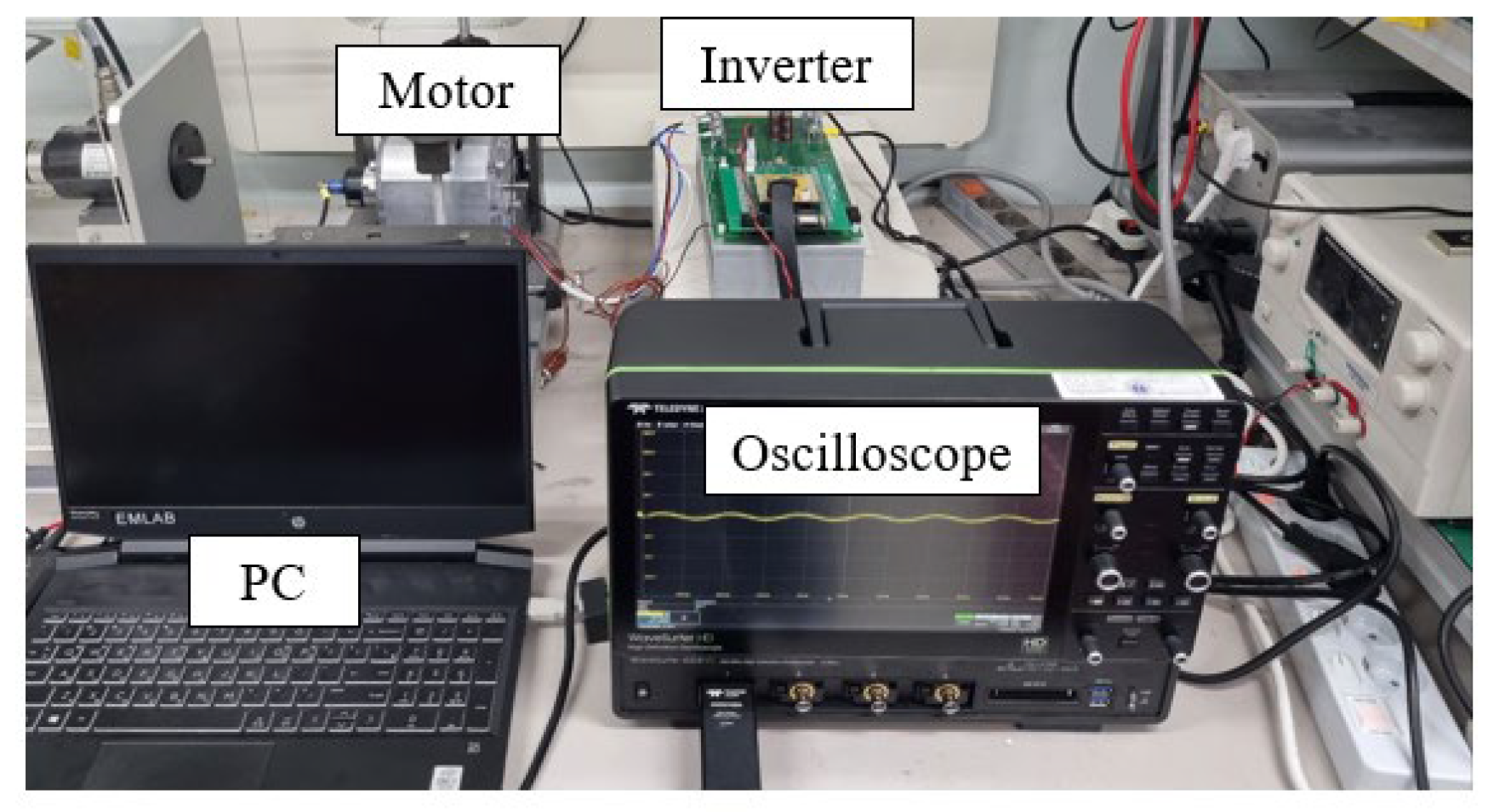
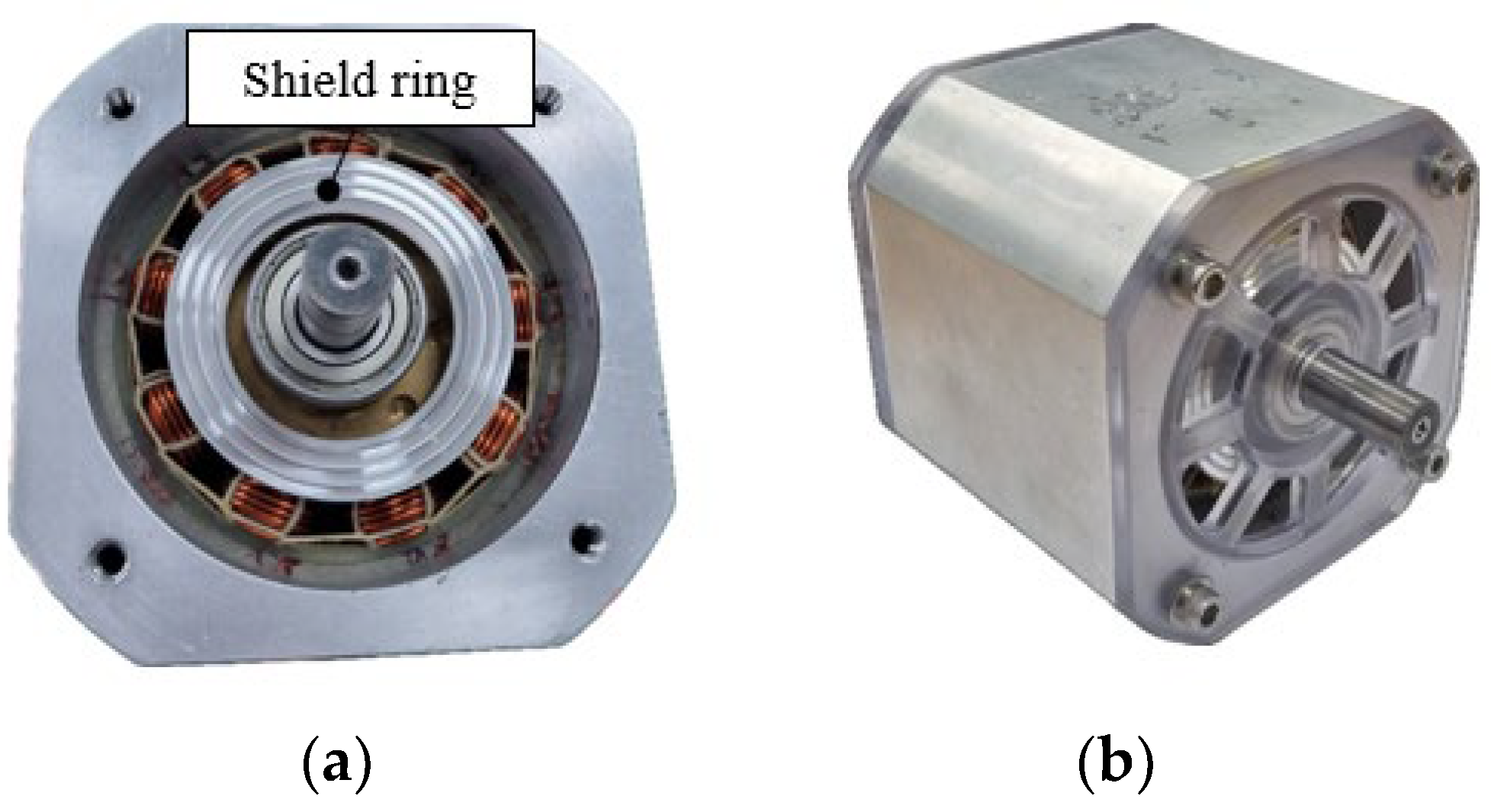
Figure 14 shows the overall experimental setup structure. Table 3 shows the specifications of the IPMSM. The shaft voltage was measured at 1000 rpm. The DC power supply device was used to apply 48 V. Figure 15 shows the structure of the IPMSM and the shield ring mounting location. As shown in Figure 15a, the shield bar was fixed between the slot openings, and the shield ring was mounted on the front and rear parts. Figure 16 shows shield rings according to material. The structure of the shield ring was the same and was manufactured using aluminum and SUS 304 materials.
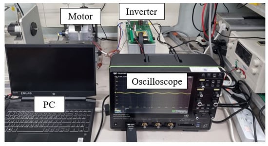
Figure 14.
Overall experimental setup.
Table 3.
Specifications of IPMSM.

Figure 15.
Structure of IPMSM. (a) Motor with shield ring; (b) overall structure of the motor.
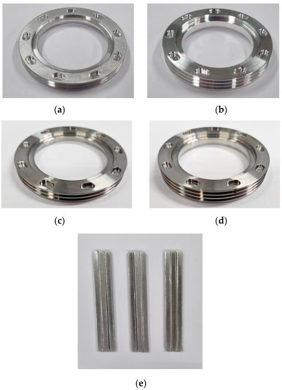
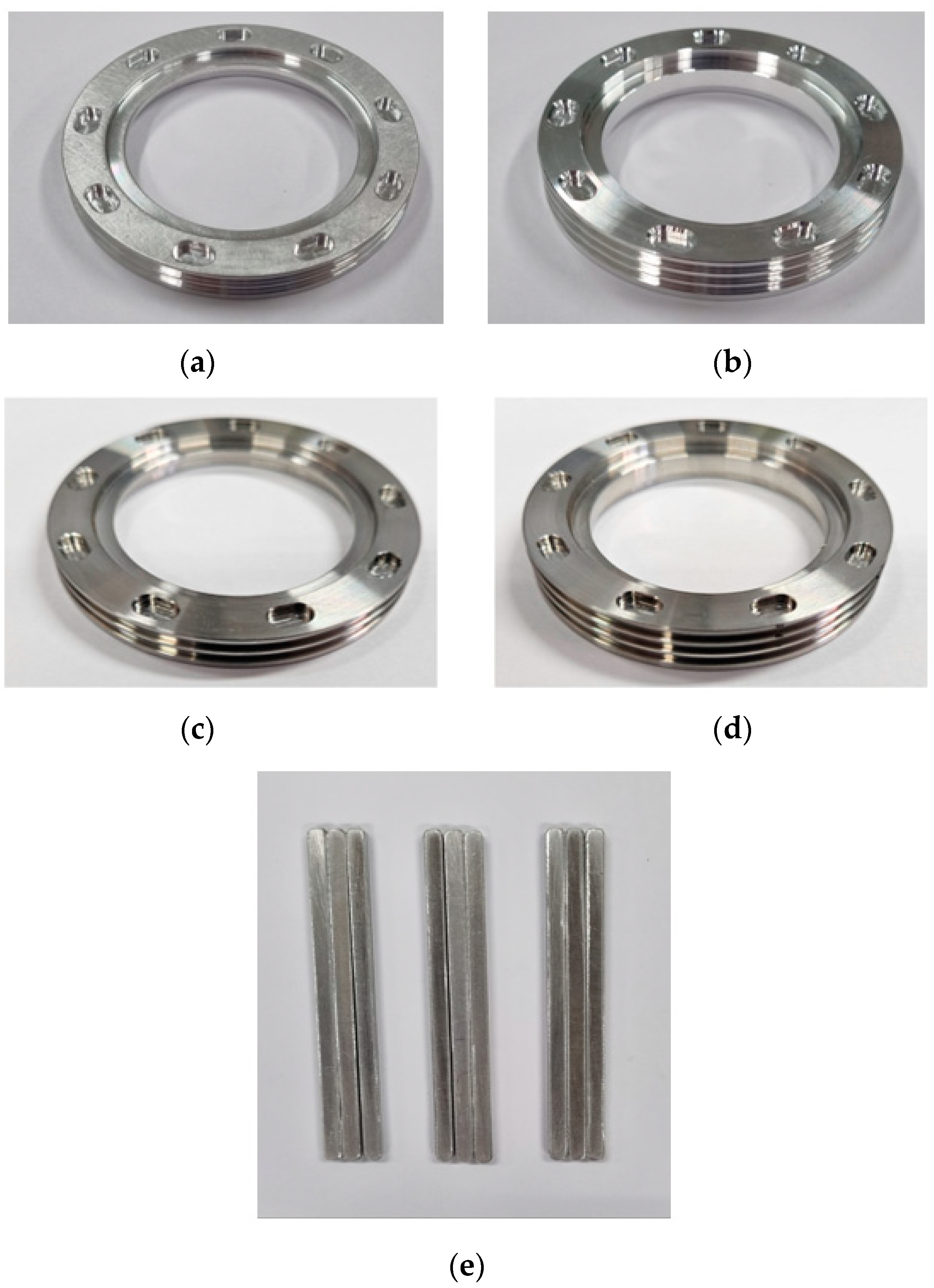
Figure 16.
Shield ring according to material. (a) Front shield ring (aluminum); (b) rear shield ring (aluminum); (c) front shield ring (SUS 304); (d) rear shield ring (SUS 304); and (e) shield bar.
4.2. Verification Results for Reducing Shaft Voltage of IPMSM
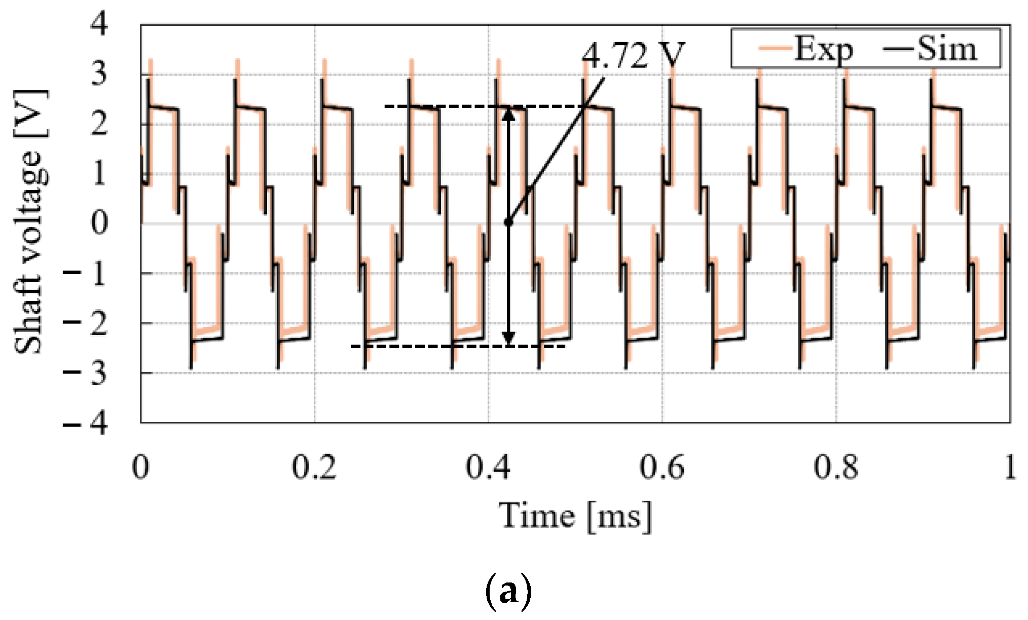
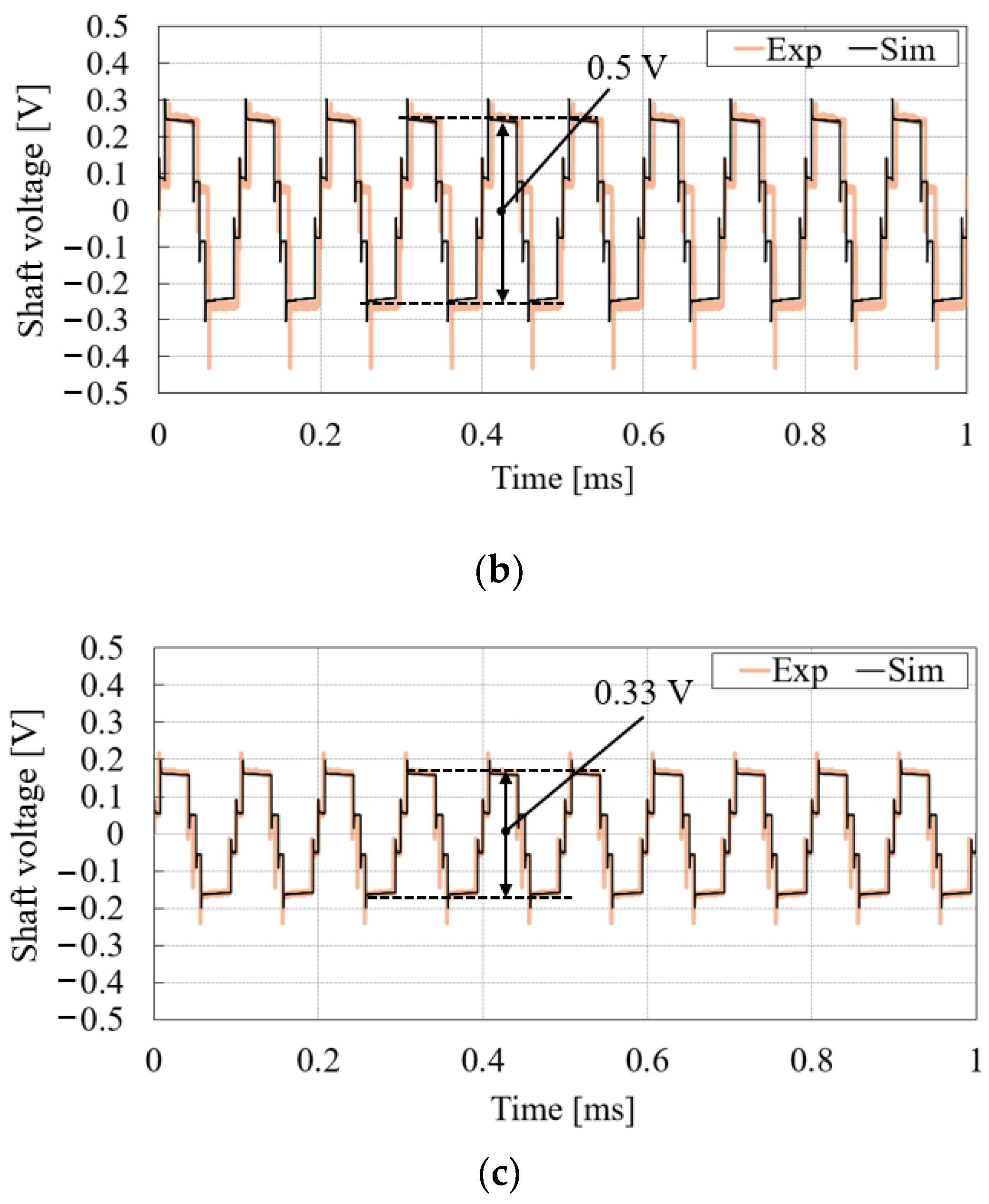
The shaft voltage reduction technology was verified through experiments using a shield ring. Figure 17 shows the shaft voltage waveform according to material through experiment and the shaft voltage waveform according to material through simulation. In the case of non-shield, it was 4.72 V, as shown in Figure 17a. In the case of aluminum, it was 0.5 V, as shown in Figure 17b. In the case of SUS 304, it was 0.33 V, as shown in Figure 17c. Here, it can be seen that the shaft voltage measured through simulation and experiment was the same. As a result, when SUS 304 was used, the shaft voltage was reduced by 93% compared to non-shield. Therefore, through experiments, it was verified that the shaft voltage reduction effect was the best when applying the SUS 304 shield ring with the same results as the simulation. Figure 18 shows that it was driven at 500 rpm depending on the material, and it was verified that the shaft voltage reduction effect was the same depending on the speed. Additionally, shaft voltage did not change with speed.
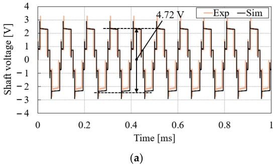
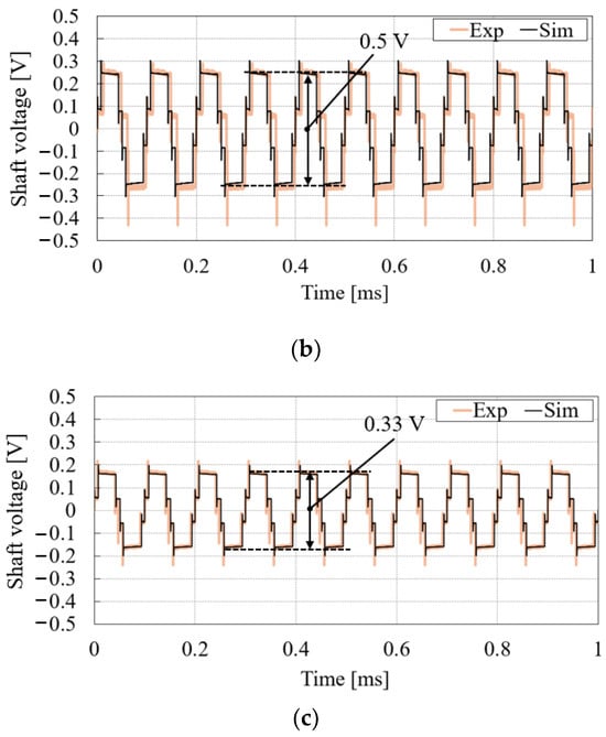
Figure 17.
Shaft voltage measurement results through simulation and experiments at 1000 rpm. (a) Non-shield; (b) aluminum; and (c) SUS 304.
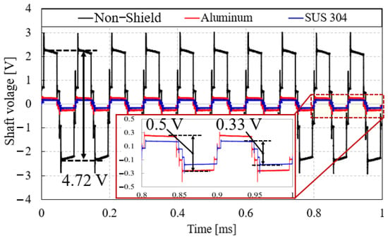
Figure 18.
Shaft voltage measurement results through the experiment at 500 rpm.
4.3. Temperature Analysis of IPMSM Considering Shield Ring
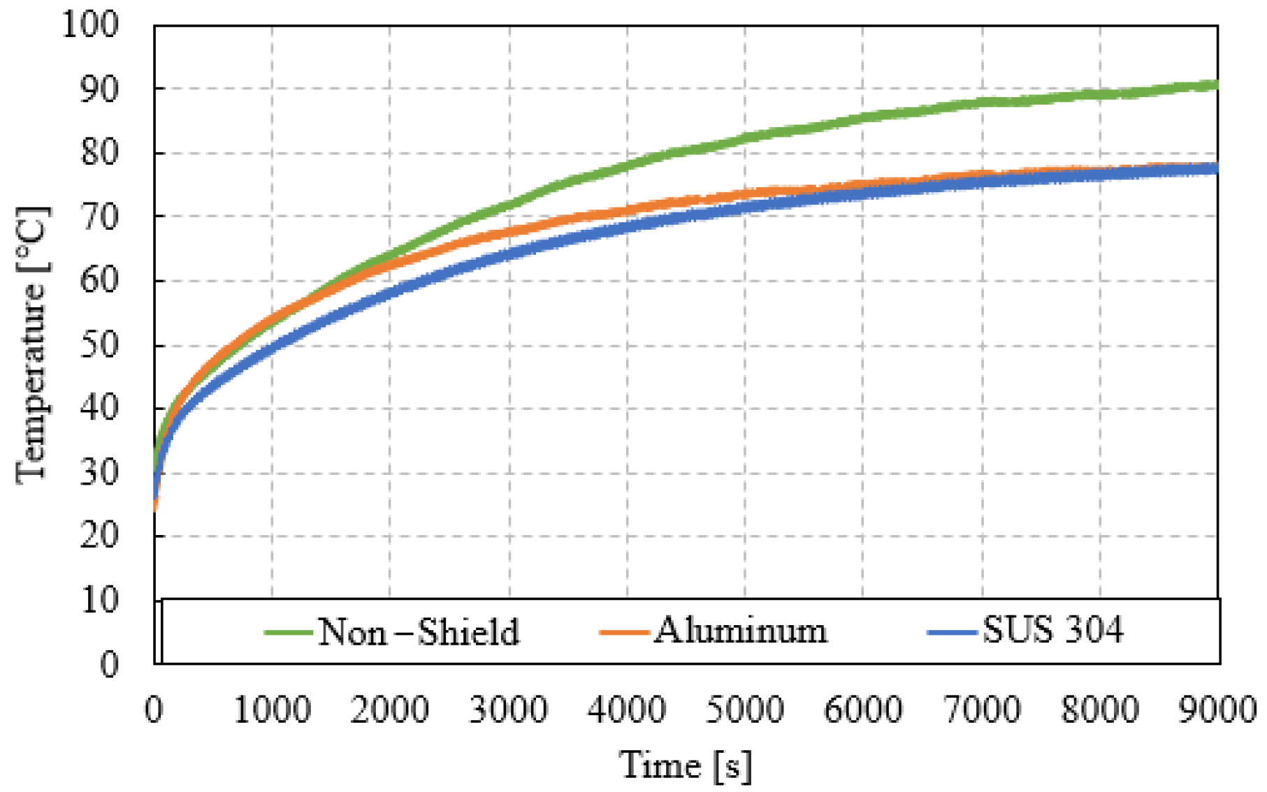
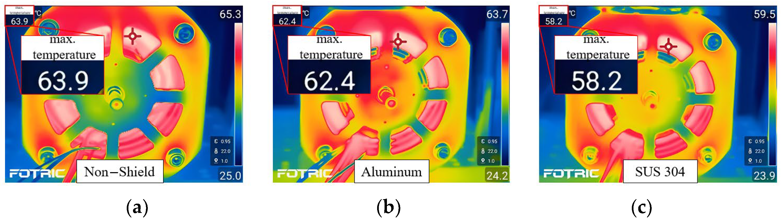
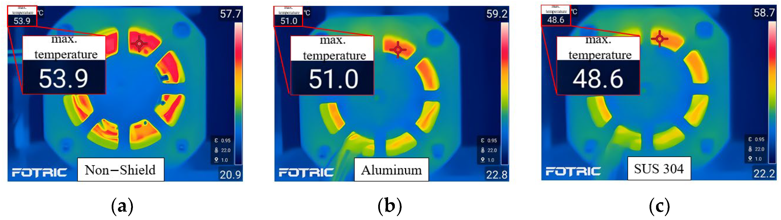
Motor cooling technology is very important for achieving high efficiency and high output and ensuring durability. There are various cooling methods to discharge the heat generated by the motor. First, there is an air-cooling method using air; a water-cooling method, in which coolant is cooled by flowing coolant through the passage of the motor housing; and an oil-cooling method that is sprayed directly into the inside of the motor [31]. Therefore, this study uses a shield ring, as shown in Figure 7, to reduce the heat source generated from the stator. Figure 19 shows the eddy current loss of the shield bars. The eddy current loss occurring in aluminum was 197.7 mW, and the eddy current loss occurring in SUS 304 was 7.2 mW. Figure 20 shows the results of a temperature experiment using a shield ring. The experiment was conducted by attaching a thermocouple sensor to the winding part. The operating speed of the experiment was 1000 rpm, and 10 Arms was applied. Figure 21 shows the results of applying a speed of 1000 rpm and a current of 10 Arms and measuring the winding temperature at 2000 s using a thermal imaging camera. Figure 22 shows the results of applying a speed of 500 rpm and a current of 10 Arms and measuring the winding temperature at 2000 s using a thermal imaging camera. When comparing Figure 21 and Figure 22, since iron loss is proportional to speed and this affects temperature, the overall temperature appears higher when driven at 1000 rpm than when driven at 500 rpm. As shown in Figure 20, the non-shield case was saturated at 90.7 °C. In the case of aluminum, it was saturated at 78 °C. Finally, in the case of SUS 304, it was saturated at 77.6 °C and had the best cooling performance. Therefore, in the case of SUS 304, the winding temperature was reduced by 14.4% compared to the non-shield condition. This has the advantage of enabling a more compact design because the cooling performance of the motor improved. Therefore, the eddy current loss of the SUS 304 shield was much smaller than that of the aluminum shield. This resulted in a decrease in winding temperature when using an SUS 304 shield compared to an aluminum shield.
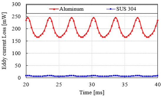
Figure 19.
Eddy current losses in shield bars at 1000 rpm.
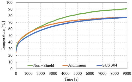
Figure 20.
Experimental values for winding temperature.

Figure 21.
Measurement results using a thermal imaging camera at 1000 rpm. (a) Non-shield; (b) aluminum; and (c) SUS 304.
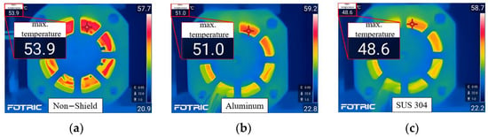
Figure 22.
Measurement results using a thermal imaging camera at 500 rpm. (a) Non-shield; (b) aluminum; and (c) SUS 304.
5. Conclusions
This paper proposes a method to prevent EDM inside the bearing by reducing the shaft voltage of IPMSM through a novel hybrid shield ring structure. EDM phenomenon occurring within the bearing can lead to bearing faults. Therefore, reducing shaft voltage is crucial. Additionally, a method of improving the cooling performance of the motor through a hybrid shield ring was analyzed. The proposed method aims to reduce shaft voltage by altering the parasitic capacitance of the electric motor through a shield ring. In conclusion, when a shield ring made of SUS 304 is applied, the effect of reducing shaft voltage is the best, and cooling performance also improved. In the case of a shield ring made of SUS 304, the cooling performance is excellent because the eddy current loss is significantly smaller than that of an aluminum shield ring. In particular, since the cooling performance of the motor improved, a more compact design is possible. Furthermore, as the shield ring does not interfere with the rotor, it does not affect motor operation. In particular, the proposed shield ring structure is easy to manufacture because it does not have a complex design. The greatest advantage is its high durability and maintenance-free operation. Therefore, by proposing research on shaft voltage reduction and analyzing various characteristics according to the shield ring, the safety and durability of the motor in the motor drive system can be secured.
Author Contributions
Conceptualization, J.-K.K.; methodology, J.-K.K.; software, J.-H.H.; validation, J.-H.H. and S.-H.K.; formal analysis, J.-K.K.; investigation, J.-H.H.; resources, S.-H.K.; data curation, J.-K.K.; writing—original draft preparation, J.-K.K.; writing—review and editing, J.-K.K.; supervision, J.H.; project administration, J.H. and J.-K.K.; funding acquisition, J.H. All authors have read and agreed to the published version of the manuscript.
Funding
This work was supported by Industrial Strategic Technology Development Program of Korea Planning & Evaluation Institute of Industrial Technology (KEIT) (No. 20018442, 00403739).
Data Availability Statement
Data are contained within the article.
Conflicts of Interest
The authors declare no conflicts of interest.
References
- Niu, G.; Shang, F.; Krishnamurthy, M.; Garcia, J.M. Design and Analysis of an Electric Hydraulic Hybrid Powertrain in Electric Vehicles. IEEE Trans. Transp. Electrif. 2017, 3, 48–57. [Google Scholar] [CrossRef]
- Zhou, L.; Zhao, Y.; Li, D.; Wang, Z. State-of-Health Estimation for LiFePO4 Battery System on Real-World Electric Vehicles Considering Aging Stage. IEEE Trans. Transp. Electrif. 2022, 8, 1724–1733. [Google Scholar] [CrossRef]
- Zhang, X.; Wang, Y.; Yuan, X.; Shen, Y.; Lu, Z. Adaptive Dynamic Surface Control with Disturbance Observers for Battery/Supercapacitor-Based Hybrid Energy Sources in Electric Vehicles. IEEE Trans. Transp. Electrif. 2023, 9, 5165–5181. [Google Scholar] [CrossRef]
- Popescu, M.; Goss, J.; Staton, D.A.; Hawkins, D.; Chong, Y.C.; Boglietti, A. Electrical Vehicles—Practical Solutions for Power Traction Motor Systems. IEEE Trans. Ind. Appl. 2018, 54, 2751–2762. [Google Scholar] [CrossRef]
- Zhang, Y.; Ai, Z.; Chen, J.; You, T.; Du, C.; Deng, L. Energy-Saving Optimization and Control of Autonomous Electric Vehicles with Considering Multiconstraints. IEEE Trans. Cybern. 2022, 52, 10869–10881. [Google Scholar] [CrossRef] [PubMed]
- Liu, Y.; Liu, K.; Zhou, Y.; Chen, Y.; Wei, D.; Zhou, S.; Luan, H. Study on the Design and Speed Ratio Control Strategy of Continuously Variable Transmission for Electric Vehicle. IEEE Access 2023, 11, 107880–107891. [Google Scholar] [CrossRef]
- Jelodar, Y.J.; Salari, O.; Youssef, M.Z.; Ebrahimi, J.; Bakhshai, A. A Novel Control Scheme for Traction Inverters in Electric Vehicles with an Optimal Efficiency Across the Entire Speed Range. IEEE Access 2024, 12, 25906–25916. [Google Scholar] [CrossRef]
- Jung, C. Power Up with 800-V Systems: The benefits of upgrading voltage power for battery-electric passenger vehicles. IEEE Electrif. Mag. 2017, 5, 53–58. [Google Scholar] [CrossRef]
- Aghabali, I.; Bauman, J.; Kollmeyer, P.J.; Wang, Y.; Bilgin, B.; Emadi, A. 800-V Electric Vehicle Powertrains: Review and Analysis of Benefits, Challenges, and Future Trends. IEEE Trans. Transp. Electrif. 2021, 7, 927–948. [Google Scholar] [CrossRef]
- Wu, S.-T.; Chiu, Y.-W. Implementation of a Bidirectional 400–800 V Wireless EV Charging System. IEEE Access 2024, 12, 26667–26682. [Google Scholar] [CrossRef]
- Cittanti, D.; Stella, F.; Vico, E.; Liu, C.; Shen, J.; Xiu, G.; Bojoi, R. Analysis, Design, and Experimental Assessment of a High Power Density Ceramic DC-Link Capacitor for a 800 V 550 kVA Electric Vehicle Drive Inverter. IEEE Trans. Ind. Appl. 2023, 59, 7078–7091. [Google Scholar] [CrossRef]
- Ding, X.; Du, M.; Duan, C.; Guo, H.; Xiong, R.; Xu, J.; Cheng, J.; kwong Luk, P.C. Analytical and Experimental Evaluation of SiC-Inverter Nonlinearities for Traction Drives Used in Electric Vehicles. IEEE Trans. Veh. Technol. 2018, 67, 146–159. [Google Scholar] [CrossRef]
- Wang, W.; Song, Q.; Zhang, S.; Li, Y.; Ahmad, M.; Gong, Y. The Loss Analysis and Efficiency Optimization of Power Inverter Based on SiC mosfets Under the High-Switching Frequency. IEEE Trans. Ind. Appl. 2021, 57, 1521–1534. [Google Scholar] [CrossRef]
- Qiu, Z.; Huang, X.; Ma, K.; Kong, Z.; Liu, X. Sideband Vibro-Acoustic Responses and Improvements with Different Pulsewidth Modulation Strategies in Permanent Magnet Synchronous Motor for Electric Vehicle. IEEE J. Emerg. Sel. Top. Power Electron. 2022, 10, 7098–7108. [Google Scholar] [CrossRef]
- Phukan, R.; Zhao, X.; Asfaux, P.; Dong, D.; Burgos, R. Investigation of Staggered PWM Scheme for AC Common Mode Current Minimization in SiC-Based Three-Phase Inverters. IEEE Trans. Transp. Electrif. 2022, 8, 4378–4390. [Google Scholar] [CrossRef]
- Guo, F.; Diab, A.M.; Yeoh, S.S.; Yang, T.; Bozhko, S.; Wheeler, P.; Zhao, Y. An Advanced Dual-Carrier-Based Multi-Optimized PWM Strategy of Three-Level Neutral-Point-Clamped Converters for More-Electric-Aircraft Applications. IEEE Trans. Energy Convers. 2024, 39, 356–367. [Google Scholar] [CrossRef]
- Singleton, R.K.; Strangas, E.G.; Aviyente, S. The Use of Bearing Currents and Vibrations in Lifetime Estimation of Bearings. IEEE Trans. Ind. Inform. 2017, 13, 1301–1309. [Google Scholar] [CrossRef]
- Hava, A.M.; Ün, E. A High-Performance PWM Algorithm for Common-Mode Voltage Reduction in Three-Phase Voltage Source Inverters. IEEE Trans. Power Electron. 2011, 26, 1998–2008. [Google Scholar] [CrossRef]
- Muetze, A.; Binder, A. Calculation of Motor Capacitances for Prediction of the Voltage Across the Bearings in Machines of Inverter-Based Drive Systems. IEEE Trans. Ind. Appl. 2007, 43, 665–672. [Google Scholar] [CrossRef]
- Muetze, A.; Tamminen, J.; Ahola, J. Influence of Motor Operating Parameters on Discharge Bearing Current Activity. IEEE Trans. Ind. Appl. 2011, 47, 1767–1777. [Google Scholar] [CrossRef]
- Chin, J.-W.; Kim, D.-J.; Park, S.; Jung, H.-C. Comprehensive Experimental Study on Shaft Voltage of Traction Motor with Ceramic Bearing for Electric Vehicles. In Proceedings of the 2023 IEEE Vehicle Power and Propulsion Conference (VPPC), Milan, Italy, 24–27 October 2023; pp. 1–6. [Google Scholar]
- Im, J.-H.; Lee, Y.-K.; Park, J.-K.; Hur, J. Shaft Voltage Reduction Method Using Carrier Wave Phase Shift in IPMSM. Energies 2021, 14, 6924. [Google Scholar] [CrossRef]
- Muetze, A.; Oh, H.W. Design Aspects of Conductive Microfiber Rings for Shaft-Grounding Purposes. IEEE Trans. Ind. Appl. 2008, 44, 1749–1757. [Google Scholar] [CrossRef]
- Park, J.-K.; Wellawatta, T.R.; Choi, S.-J.; Hur, J. Mitigation Method of the Shaft Voltage According to Parasitic Capacitance of the PMSM. IEEE Trans. Ind. Appl. 2017, 53, 4441–4449. [Google Scholar] [CrossRef]
- Zhao, Z.; Zhong, Y.; Gao, H.; Yuan, L.; Lu, T. Hybrid Selective Harmonic Elimination PWM for Common-Mode Voltage Reduction in Three-Level Neutral-Point-Clamped Inverters for Variable Speed Induction Drives. IEEE Trans. Power Electron. 2012, 27, 1152–1158. [Google Scholar] [CrossRef]
- Kwak, S.; Mun, S.-K. Model Predictive Control Methods to Reduce Common-Mode Voltage for Three-Phase Voltage Source Inverters. IEEE Trans. Power Electron. 2015, 30, 5019–5035. [Google Scholar] [CrossRef]
- Nakahama, T.; Biswas, D.; Kawano, K.; Ishibashi, F. Improved cooling performance of large motors using fans. IEEE Trans. Energy Convers. 2006, 21, 324–331. [Google Scholar] [CrossRef]
- Wang, H.; Liu, X.; Kang, M.; Guo, L.; Li, X. Oil Injection Cooling Design for the IPMSM Applied in Electric Vehicles. IEEE Trans. Transp. Electrif. 2022, 3, 3427–3440. [Google Scholar] [CrossRef]
- Park, J.-K.; Wellawatta, T.R.; Ullah, Z.; Hur, J. New Equivalent Circuit of the IPM-Type BLDC Motor for Calculation of Shaft Voltage by Considering Electric and Magnetic Fields. IEEE Trans. Ind. Appl. 2016, 52, 3763–3771. [Google Scholar] [CrossRef]
- Balanis, C.A. Advanced Engineering Electromagnetics, 2nd ed.; Wiley: Hoboken, NJ, USA, 2012; pp. 56–59. [Google Scholar]
- Xu, Z.; Xu, Y.; Gai, Y.; Liu, W. Thermal Management of Drive Motor for Transportation: Analysis Methods, Key Factors in Thermal Analysis, and Cooling Methods—A Review. IEEE Trans. Transp. Electrif. 2023, 9, 4751–4774. [Google Scholar] [CrossRef]

Disclaimer/Publisher’s Note: The statements, opinions and data contained in all publications are solely those of the individual author(s) and contributor(s) and not of MDPI and/or the editor(s). MDPI and/or the editor(s) disclaim responsibility for any injury to people or property resulting from any ideas, methods, instructions or products referred to in the content. |
© 2024 by the authors. Licensee MDPI, Basel, Switzerland. This article is an open access article distributed under the terms and conditions of the Creative Commons Attribution (CC BY) license (https://creativecommons.org/licenses/by/4.0/).