Abstract
Energy harvesting technologies are becoming increasingly popular as potential sources of energy for Internet of Things (IoT) devices. Magnetic field energy harvesting (MFEH) from current-carrying components, such as power cables, represents a particularly promising technology for smart grid, infrastructure, and environmental monitoring applications. This paper presents a single-stage AC/DC power converter, a control architecture, and an energy harvester design applicable to MFEH devices. The power converter consists of a MOSFET full bridge that is used to actively rectify the induced voltage at the transceiver while providing a regulated output voltage. The approach is suitable for a broad range of grid power lines, offering a compact power stage that achieves a reduction in component count while active rectification minimizes energy losses, thereby improving thermal management in power electronics compared with the previous research. The experimental results demonstrate that the power converter provides a stable energy source and offers an alternative to self-powering smart grid IoT devices.
1. Introduction
The electrical power grid is encouraging the transition to more sustainable energy sources and processes, with the objective of reducing the consumption of fossil fuels and expanding the integration of renewable energy sources [1]. The electrical system is confronted with significant challenges that have emerged from the integration of distributed energy resources, electric vehicles, and energy storage, while conventional thermal plants are being decommissioned, resulting in a more complex power grid [2,3]. This new approach presents challenges to distribution networks that were originally designed under different conditions, including the management of congestion and the maintenance of a consistent balance between supply and demand. Furthermore, there is a gradual increase in the number of electronic devices being used as inverters, power supplies, or battery chargers based on power electronics that produce the harmonic distortion of either voltage or current waveforms as a result of the inherent nonlinearity of technology [4,5]. Moreover, the deployment of additional distribution and transmission lines to increase power capacity will require additional efforts [6], including more frequent maintenance and more rigorous inspection procedures to guarantee the resilience of the grid [7]. As a result, there is a growing interest in more sophisticated grid monitoring techniques [8,9] and more effective assessment methods to ensure the reliability of electrical networks [10,11] and to maintain the continuity of supply and the quality of service, thereby strengthening grid resilience [12,13].
With the increasing number of connected devices, the Internet of Things (IoT) is becoming a global phenomenon that is transforming the industry [14]. The IoT is gradually developing a vast network of interconnecting devices that can provide data through sensors [15]. This expansion is driven by a number of technological developments, including upgraded connectivity features that enable advanced communication networks [16], ultra-low power microprocessors that equip edge computing capabilities [17], and the evolution of sophisticated algorithms powered by AI that analyze and compute large volumes of data [11]. On the other hand, edge computing offers a solution by distributing the computational load across different elements connected to the network, facilitating its scalability [18]. As a result, the IoT is fostering new opportunities to increase reliability and efficiency in the industry and the electrical sector [19].
The deployment of monitoring devices for smart grids in distribution or transmission power lines necessitates the provision of an energy source, such as batteries. However, this is often impractical for a multitude of applications, primarily due to the considerable number of devices and the challenging accessibility of their locations [20,21]. It is therefore evident that energy harvesting represents a crucial element in ensuring the uninterrupted operation of maintenance-free smart grid devices [22,23,24,25,26,27]. Magnetic field energy harvesting (MFEH) is a technology that enables the capture and conversion of the magnetic field present around power lines into a form of energy that can be used to power IoT devices. MFEH enables the utilization of the AC current-carrying components of the power grid, such as overhead and underground power cables, as an energy source without the necessity for voltage transformation [28,29,30,31,32]. In comparison with alternative energy harvesting techniques that capture ambient energy, including solar, wind, thermal, mechanical vibrations, radio frequency, or electric fields, MFEH from power cables is not contingent on the intermittent nature of the source [33,34,35,36]. Furthermore, it has high energy density, which makes it a promising technology for smart grids to provide energy from the current flows present in the conductor in a non-intrusive way [30,37,38].
The energy consumption of an IoT device may vary depending on several factors, including the number and type of sensors, the frequency of data refresh, the complexity of processing algorithms, the nature of data transmission and reception, and the activation of power-saving features. MFEH technology represents a viable alternative that can serve as an energy source, while simultaneously extending the lifespan of sensors and reducing maintenance downtime and operational expenses [39,40,41]. An IoT device based on MFEH technology typically comprises the following essential components [42,43,44]:
- Transducer: A device that harvests energy from magnetic fields by utilizing a ferromagnetic core which concentrates the magnetic flux and induces the secondary coil from the AC current-carrying component. Consequently, the MFEH is also referred to as inductive energy harvesting.
- Power converter: A power electronic stage that converts the induced voltage in the transducer into a suitable form of electricity for electronic devices.
- Energy storage: Stores harvested energy to provide a regulated DC bus. A supercapacitor or battery can be used to decouple the energy source from the load.
- Sensors and microcontroller: For data collection and information management. This involves edge computing, connectivity, data storage, and user interfaces.
Extensive research has been conducted in the field of MFEH, addressing various critical aspects. In [21], a magnetic energy harvester device and multistage power supply based on a rectifier and a voltage regulation stage output circuit are proposed. Nevertheless, the experimental results are not presented. In [32], the design optimization of energy harvesting devices is analyzed, with a particular focus on magnetic devices. In [28], a multistage power converter based on a diode rectifier and two active MOSFET controllers is proposed as a means of applying a desaturation technique with a view to enhance the energy harvested. Additionally, in [29], a diode rectifier, a voltage regulator, and an active MOSFET control are employed to maintain the core in the non-saturation operation region via a control coil. Furthermore, an alternative approach is proposed in [31], employing a two-stage power supply based on a diode rectifier and a buck converter. In [38], the high-efficiency implementation of a two-stage battery charger that utilizes an active bridge rectifier and a synchronous buck converter is also presented.
Despite these advancements, the current state of the art predominantly relies on multistage converters to manage harvested energy. In contrast, a single-stage converter would entail a reduction in components, leading to a reduction in device cost and size. Furthermore, active rectification contributes to the minimizing of losses in power electronics, improving thermal management and positively impacting key factors. Thus, this study seeks to address this limitation by exploring the implementation of an MFEH integrated with a single-stage power converter and a control strategy. The key contributions of this research include the following:
- Development of a single-stage AC-to-DC power converter designed to reduce components and thermal losses in power electronics in the energy conversion process;
- Design and implementation of a control architecture for voltage regulation and active rectification, enhancing the performance of the proposed power stage;
- Design of the energy harvesting system tailored to achieve an extended and efficient range.
To achieve these objectives, the theoretical framework was analyzed to detail the operating principle of MFEH, which involves capturing the magnetic field generated by a power line and converting it into electrical energy to power electronic devices. The unregulated induced AC voltage from the magnetic field must be managed by a power converter. Typically, this process involves a stage that rectifies the AC voltage into a variable DC voltage, which then requires an additional regulation stage to adapt it to the desired range. This article proposes a single-stage approach that integrates active rectification and a control mechanism to regulate the DC voltage within the required operating range, thereby eliminating the need for multiple conversion stages. Circuit simulations were conducted to validate the design and assess its performance. Finally, the proposed power stage was experimentally validated in the laboratory using a prototype.
The document is structured as follows: Section 2 introduces the operating principle of the MFEH. Then, in Section 3, the approach for the single-stage power converter is explained and the functions are outlined. In Section 4, the proposed design for the energy harvesting is described. Section 5 presents the laboratory mock-up and the results for the operation at various points of interest. Finally, Section 6 provides a discussion of the findings presented in the paper.
2. Operating Principle
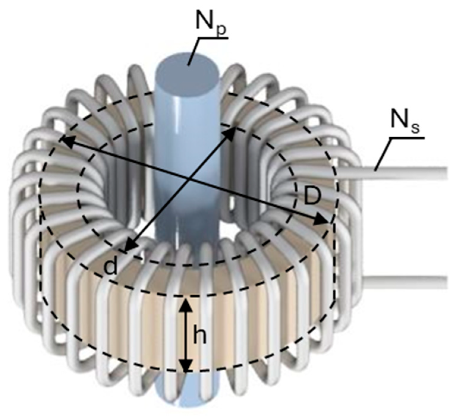
The MFEH of current-carrying components is the method of converting the energy present in the magnetic field created when an alternating current flows through a conductor into electrical energy. As shown in Figure 1, it is based on a current transformer that clamps a current-carrying component as a power line and comprises a ferromagnetic core, the power line with an AC current that constitutes the primary winding, and the secondary winding. The ferromagnetic core is composed of magnetic materials with high permeability, which create a low-reluctance pathway for the magnetic field to induce a voltage in the secondary winding. The parameters Np and Ns represent the number of turns in the primary and secondary windings, while D, d, and h represent the outer diameter, inner diameter, and height, respectively.
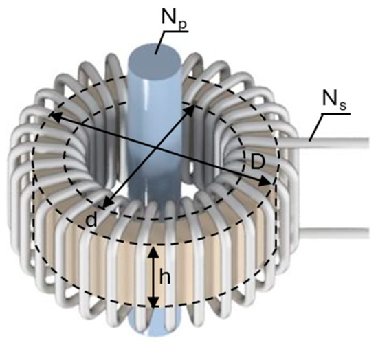
Figure 1.
Magnetic field energy harvester comprising a ferromagnetic core and secondary coil situated within a power line.
The secondary coil’s induced voltage is derived from Faraday’s law of electromagnetic induction. This law states that the electromotive force induced in a closed loop is directly proportional to the rate of change of magnetic flux through the loop. In mathematical form, Faraday’s law is expressed as follows:
where Ɛ(t) represents the induced electromotive force, Φ(t) denotes the magnetic flux, and Ns signifies the number of turns on the secondary coil. The negative sign indicates that the induced electromotive force creates a voltage that opposes the change in magnetic flux in accordance with Lenz’s law as a consequence of the law of conservation of energy. In order to establish the induced electromotive force, it is necessary to determine the magnetic flux in the ferromagnetic core passing through a differential area (dS) perpendicular to the magnetic field direction. This can be calculated as follows:
The magnetic flux is dependent on the magnetic flux density B(t), which is determined by the magnetic permeability µ of a material in function of the magnetic field strength H(t) applied by the power line. This relationship is expressed in the following equation:
The permeability is a measure of the magnetization that is produced in a material in response to an applied magnetic field. There is no simple relationship between H and B because these materials have non-linear magnetic behavior and exhibit significant magnetic hysteresis, so there is not even a single-valued functional relationship. The approximate magnetic field strength applied by the power line to the ferromagnetic core is determined by means of the effective magnetomotive force , expressed in ampere-turn, divided by the effective core length .
The effective magnetomotive force is a function of the primary current and a secondary side current in a coil with Ns.
In the case of an AC power line, the primary current can be simplified by assuming a sinusoidal waveform. On the other hand, the secondary current has the same frequency as the primary current while the waveform is dependent on the active rectification and the impedance of the load.
In the case of a toroid, the effective core length, which is equivalent to the mean distance traversed by the magnetic flux lines within the magnetic circuit, is given by the following expression:
where determines the inner radius and refers to the outer radius. Then, the approximate magnetic field strength H(t) for a toroid installed on an AC power line is given by the following expression:
Consequently, the magnitude of the voltage induced in the MFEH is determined by the primary current magnitude, the load impedance, and the material properties and physical design of the ferromagnetic core. Since the energy harvester generates a variable induced voltage, a power converter is necessary to ensure a stable output voltage, effectively manage the harvested energy, and protect the connected electronic device.
3. Power Converter
The frequency of the AC voltage induced in the transducer depends on the grid frequency, which is generally 50 Hz or 60 Hz worldwide. The amplitude of the secondary voltage and current varies with the primary current and depends, among other parameters, on the ferromagnetic properties of the core material, the number of turns in the secondary winding, and the load consumption.
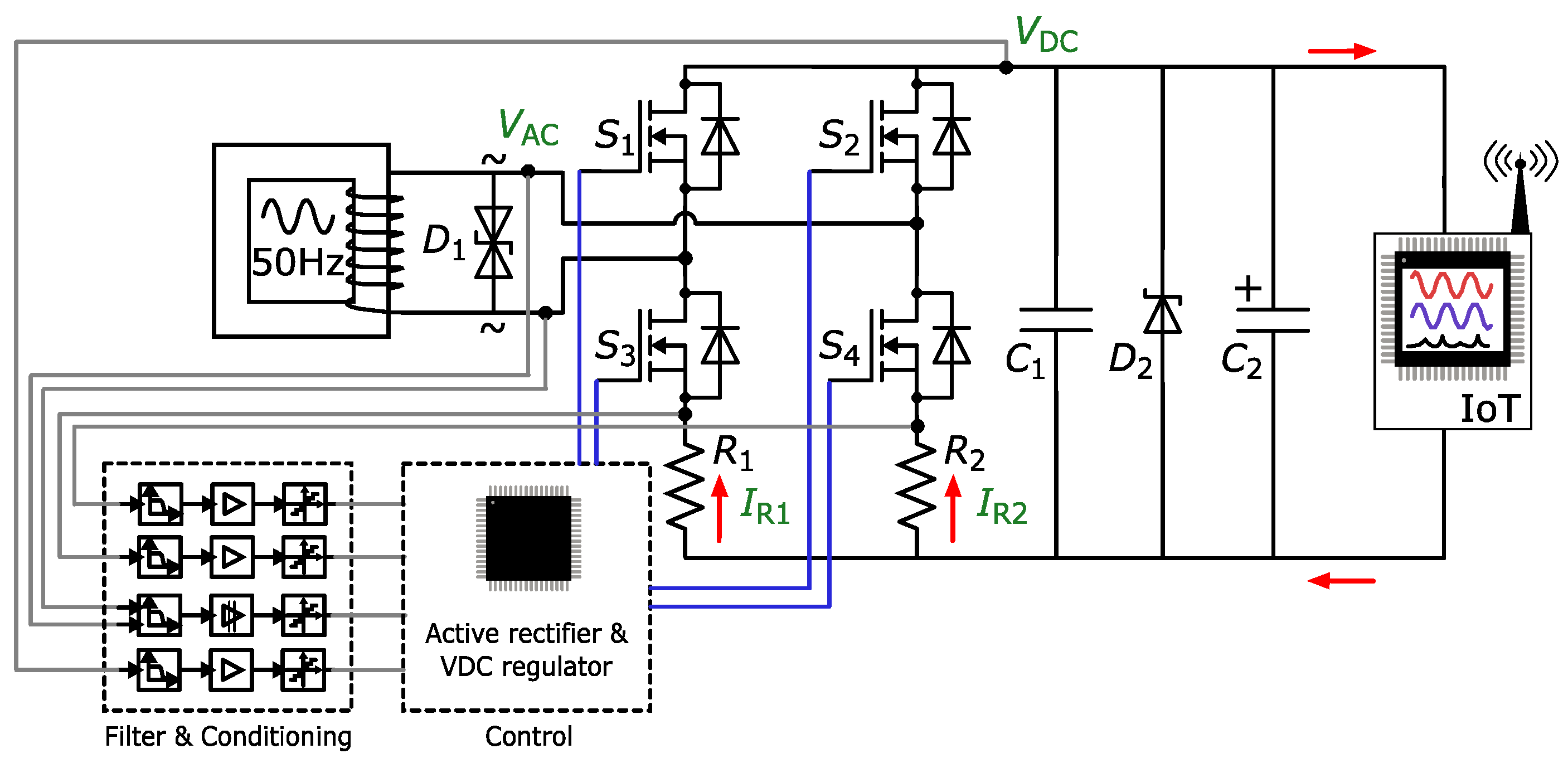
As shown in Figure 2, a single-stage MOSFET H-bridge is proposed to rectify the alternative current and manage the wide and variable voltages induced. The N-channel MOSFET bridge provides full-wave active rectification with low power losses. This topology also simplifies the thermal design, eliminates the need for heat sinks, and reduces the size of the PCB, increasing power density. To mitigate the effects of voltage spikes, the following two TVS diodes are integrated into the circuit: one bidirectional (D1) for the AC side and another unidirectional (D2) for the DC bus. A ceramic bypass capacitor (C1) is in conjunction with a large electrolytic smoothing capacitor (C2) to mitigate voltage ripple and enhance DC bus stability. The shunt resistors (R1) and (R2) are used to determine the current flowing through each H-bridge leg, while the AC voltage in the MFEH and the voltage in the DC bus are measured for control purposes.
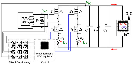
Figure 2.
Single-stage MOSFET H-bridge converter with voltage and current measurements for control loop and magnetic field energy harvesting diagram.
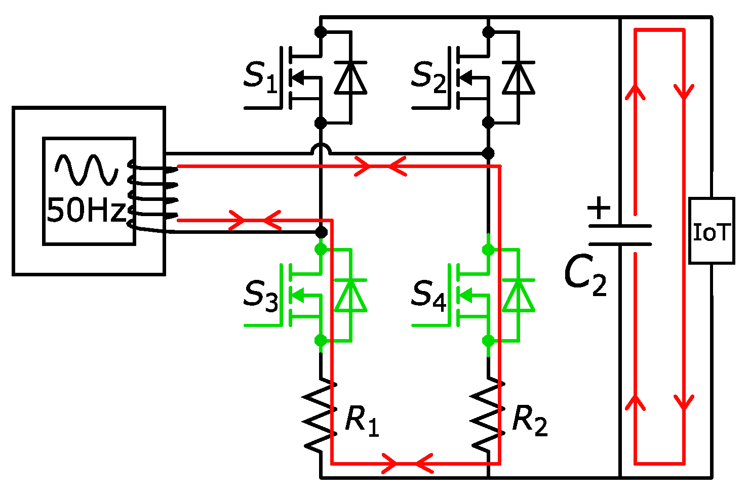
The control unit manages the DC voltage acting over the four switches of the H-bridge. Figure 3 illustrates the high-level controller that generates the enable/disable order for the active rectifier control. For this purpose, DC voltage is measured ( and compared with the voltage reference (), and the error signal () is generated. Then, the hysteresis regulator [45] enables the active rectifier if the error signal falls below the hysteresis lower limit or disables it if error rises above the upper limit. When active rectification control is disabled, as Figure 4 shows, both bottom switches (S3 and S4) are closed to short-circuit the secondary coil. This mechanism halts additional energy harvesting, regulating the voltage in the DC bus and thus preventing the occurrence of hazardous voltage levels for the electronic components. Switches S3 and S4 are activated instead of S1 and S2 to maintain the current measurement by shunt sensors R1 and R2 ( and , respectively).

Figure 3.
Block diagram of DC bus voltage control scheme in MFEH.
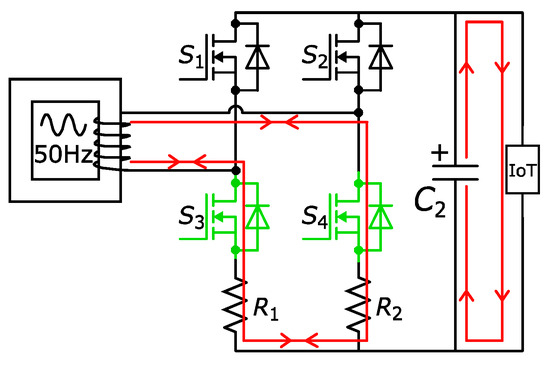
Figure 4.
DC voltage regulator forces a secondary coil short-circuit in the energy harvester to impede any further energy harvesting and prevent overvoltage in DC bus.
On the other hand, when an error signal falls below the hysteresis lower limit, the active rectifier control is enabled. In this case, all the switches are opened and and are measured to monitor the current direction, depending on whether the half-cycle is positive or negative. If takes a positive value, the AC voltage () is higher than and S2 and S3 are activated (Figure 5a) to force current flow through the MOSFET channel instead of the body diode, minimizing power losses. On the contrary, if becomes positive, then is higher than and S1 and S4 are closed (Figure 5b). Both states end when the activation condition becomes false (), measured as a direction change in and , and all the switches remain open until a new activation condition is satisfied.

Figure 5.
Active rectifier mode operating the corresponding top and bottom MOSFETs in the H-bridge for each positive (a) and negative (b) half-cycle for the active rectification of the voltage from MFEH.
The control algorithm is implemented with a loop frequency of 20 kHz, which is substantially higher than the operating frequency of the active rectifier (50–60 Hz). This high frequency enables the MOSFETs to be efficiently controlled via GPIOs. In this application, the control loop delay of 50 µs is negligible, allowing for the rapid response and precise regulation of the output voltage.
Power Electronic Stage Simulation
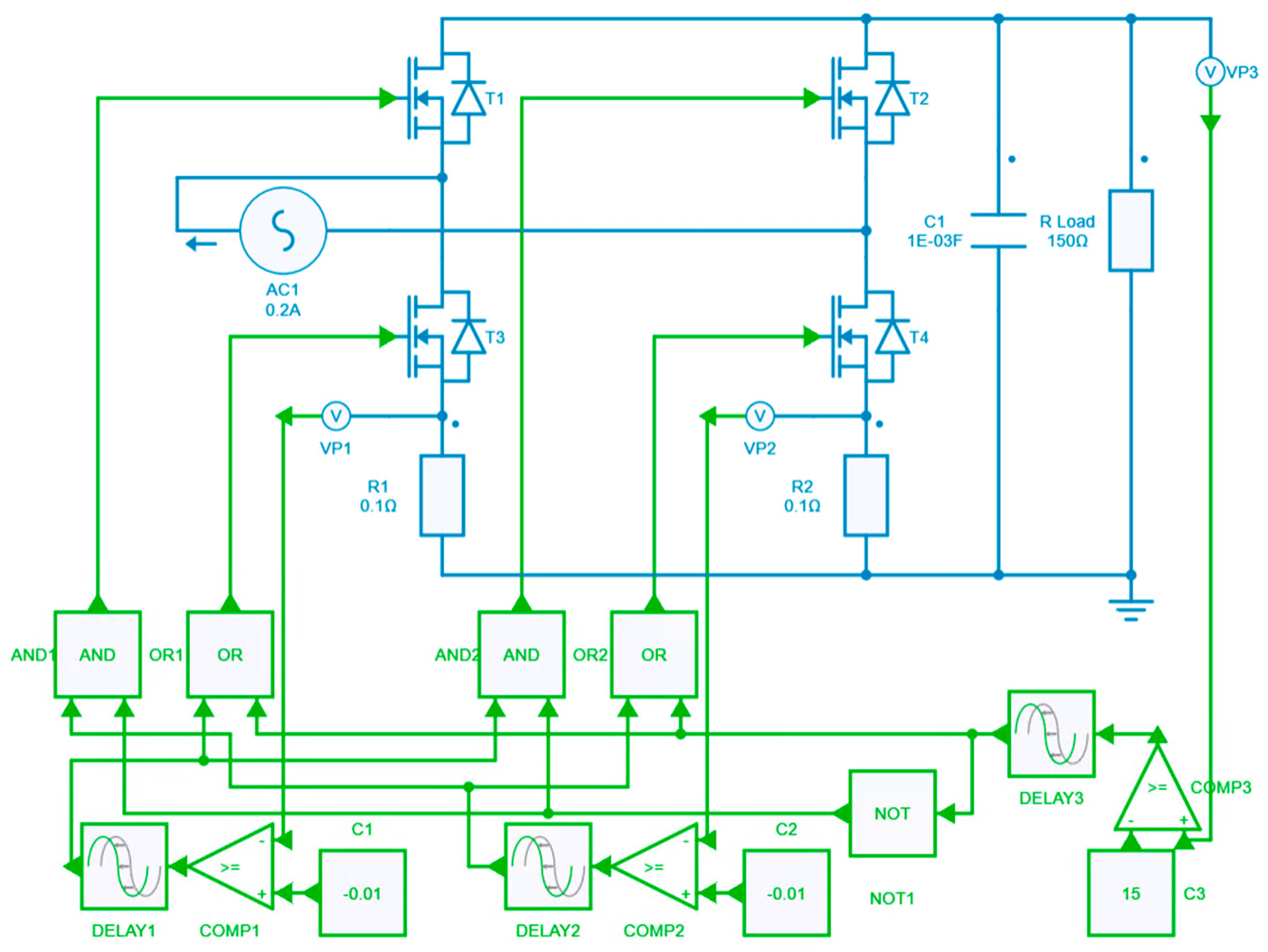
To validate the proposed power electronic converter and its control architecture, a detailed simulation was conducted using Simba simulation software V 24.11. The simulation model incorporates the key components of the system, including the transducer, the single-stage converter, and the control algorithm for active rectification and voltage regulation, as illustrated in Figure 6. COMP1 and COMP2 are employed to control active rectification by comparing the voltage across shunt resistors R1 and R2 with the voltage thresholds of registers C1 and C2, respectively. COMP3 is utilized for voltage regulation by comparing the output voltage with the setpoint defined by register C3. To account for a control loop delay of 50 µs, delay blocks are incorporated following each comparator. The primary objective of the simulation is to evaluate the performance of the system in both the initial transient and steady state conditions.
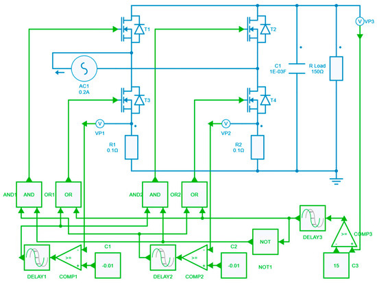
Figure 6.
Simulation diagram of the power converter and control architecture.
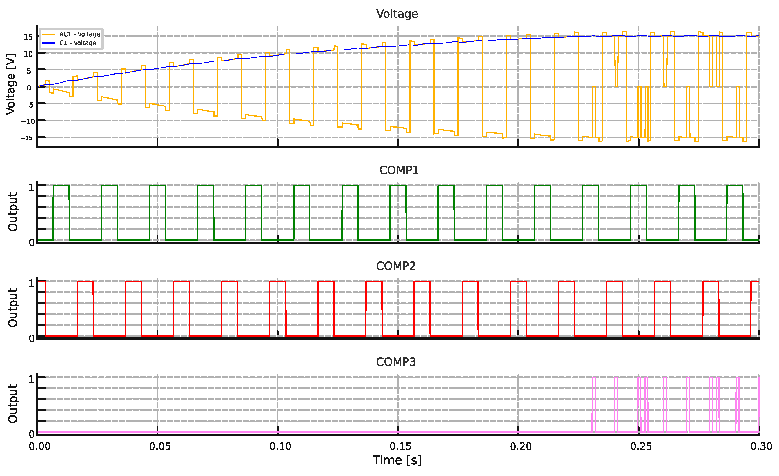
Figure 7 presents the simulation results for the initial transient response of the proposed power electronic stage and control architecture. During this phase, the control algorithm first performs active rectification to charge the DC bus capacitor. Once the target voltage setpoint is reached, the voltage regulator stabilizes the output voltage. The system’s rapid response ensures that the output voltage remains within the desired range, even under dynamic variations in harvested energy.
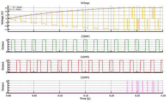
Figure 7.
Simulation results for the initial transient of the induced voltage on the MFEH transducer (yellow), the DC bus voltage (blue), and the comparators switching signals of the MOSFETs (green, red, and purple, active at 1).
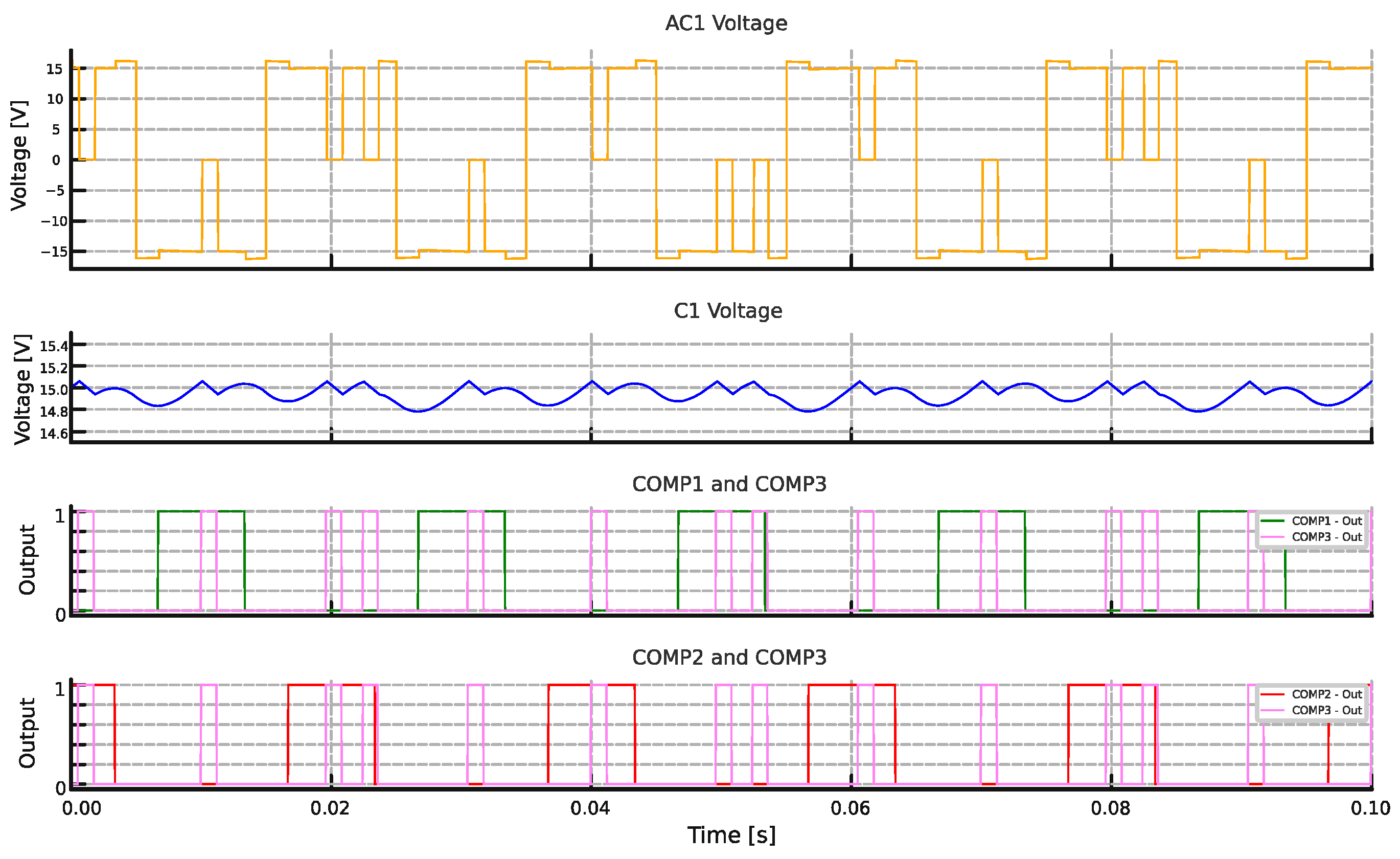
The steady state behavior of the system is detailed in Figure 8, showcasing a stable output voltage of 15 V on the DC bus with minimal ripple. The simulation demonstrates the effectiveness of the short-circuiting mechanism in preventing overvoltage conditions. During periods of surplus energy harvesting, the control loop activates the short-circuiting transducer, ensuring the DC bus voltage remains within safe limits. These findings confirm that the proposed design satisfies the operational requirements of self-powered smart grid IoT devices, providing stable, efficient, and reliable performance.
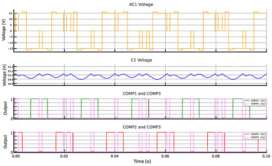
Figure 8.
Simulation results for the steady state of the induced voltage on the MFEH transducer (yellow), the DC bus voltage ripple (blue), and the comparators switching signals of the MOSFETs (green, red, and purple, active at 1).
4. Magnetic Field Energy Harvesting
The design of the MFEH transducer requires the careful consideration of its electrical characteristics to ensure compatibility with the power stage. Key elements, such as the ferromagnetic core and winding, must be optimized to achieve an appropriate output voltage range and adequate power delivery across the full spectrum of power line current variations. The objective is to establish the design for an efficient and reliable energy harvester. This will be achieved by optimizing the key parameters that define the MFEH transducer, such as the material, geometry, and number of turns. These parameters will be based on the previous studies [46] to ensure that the harvester meets the requirements of the targeted application.
The current range within power lines can vary significantly depending on the intended application. In this work, we have considered a maximum current of 600 A and a target power consumption of 1.5 W for the load, which can operate with a minimum of 10% of the maximum current (60 A) on the power line. A ferromagnetic toroid made of silicon steel was selected due to its high permeability and cost-effectiveness. To mitigate eddy currents, a laminated silicon steel core was used. Table 1 provides the design constraints and specifications for the MFEH transducer. The dimensions were chosen to accommodate high-diameter power lines while ensuring sufficient energy harvesting capability to power the load under the minimum specified conditions.

Table 1.
Magnetic field energy harvesting specifications and power line characteristics.
The relationship between voltage and current output is modified by selecting the number of turns of the secondary coil. The secondary coil was wound with 360 turns in order to achieve the desired voltage of 15 V DC after the rectification stage at the maximum power point (MPP), with a minimum primary current of 60 A.
4.1. Magnetic Field Simulations
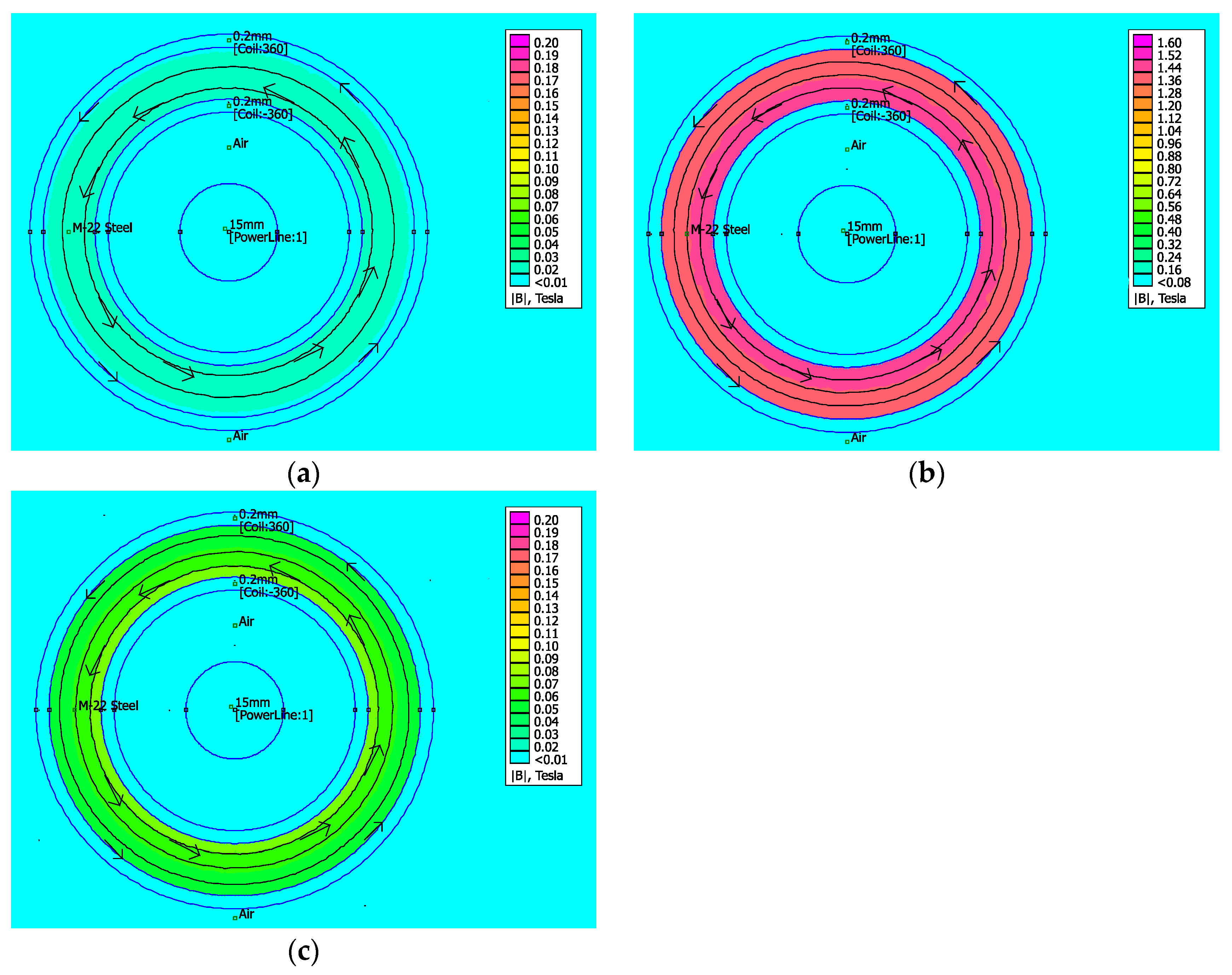
To validate the proposed approach for the MFEH transducer, a magnetic field simulation was carried out using FEMM simulation software V 4.2. The simulation model includes the ferromagnetic core, as well as the primary and secondary coils, accurately representing the physical characteristics of the system. The performance of the system was simulated at three significant operating points, representing various conditions to evaluate its effectiveness and reliability under diverse scenarios.
- Short-circuit current: A short-circuit output current is defined as occurring when the output terminals are shorted, resulting in a zero-voltage output and the secondary current being equal to the primary current divided by the number of turns in the secondary winding. In this instance, the opposed magnetic field induced in the secondary is at its maximum, as illustrated in Figure 9a. Consequently, the effective magnetic field in the ferromagnetic core is negligible, as the magnetic field generated by the power line is cancelled by the magnetic field induced in the secondary.
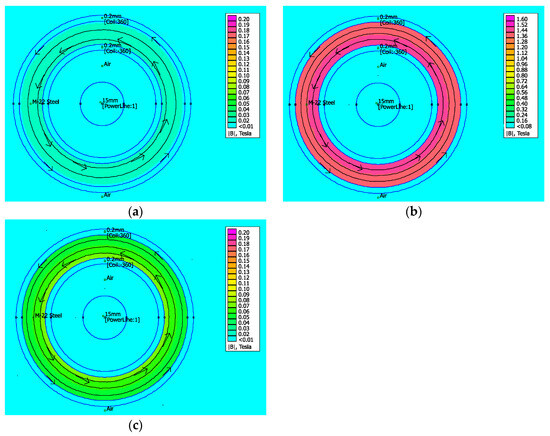 Figure 9. Finite element magnetic simulation of the MFEH transducer with a 60 A power line: (a) with the secondary short-circuited; (b) with the secondary open-circuited; (c) at the maximum power point.
 - Open-circuit voltage: An open-circuit voltage is generated when the secondary coils are not connected to any load, resulting in the maximum induced voltage without current flowing in the secondary winding. At this point, no magnetic field opposes the primary in the secondary, validating that the geometry selected is able to guide effectively the magnetic field, reaching saturation levels of 1.6 T, as can be observed in Figure 9b.
- Maximum Power Point: The MPP is defined as the point at which the relationship between the voltage induced and the secondary current is at its maximum, resulting in the highest possible output power for a determined current in the primary coils.
4.2. MFEH Prototype
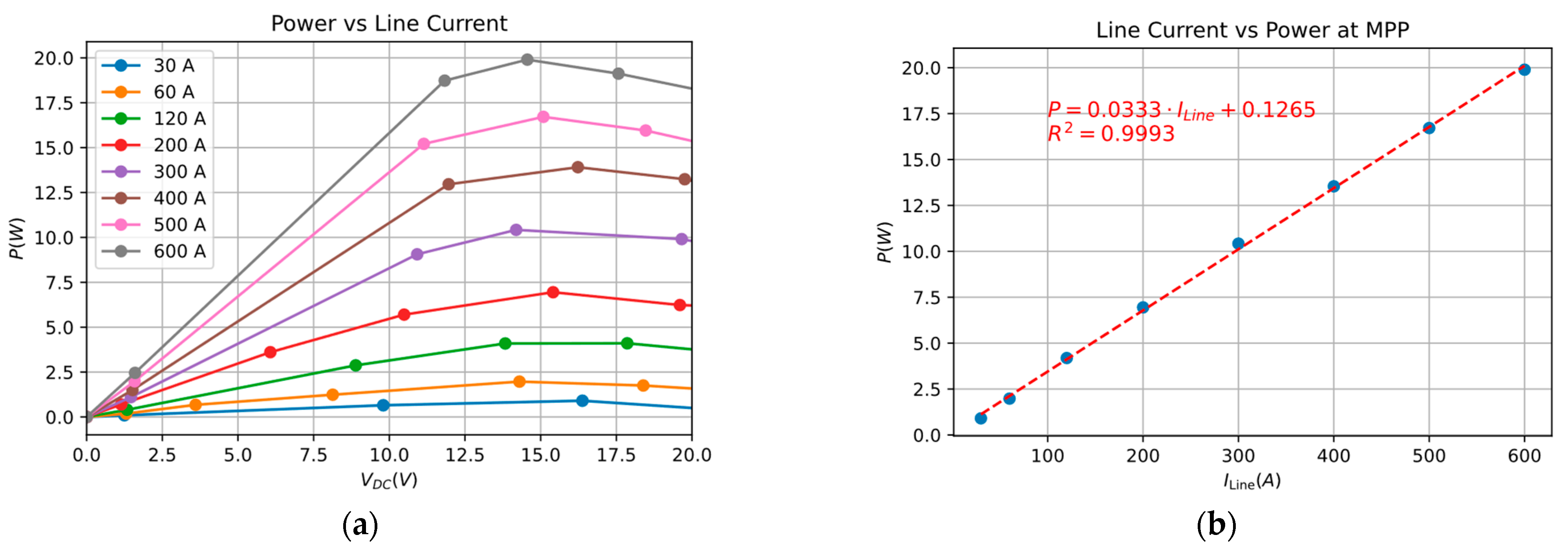
The electrical behavior of the MFEH prototype in function of the primary current is shown in Figure 10, which is based on Table 2. As illustrated in Figure 10a, when the primary current is 60 A, more than 1.5 W can be harvested when 15 V DC are supplied to the load. As the primary current increases, more and more energy can be harvested for the target voltage, ensuring proper operation with a load of 1.5 W. The characterization of the MFEH reveals a direct relationship between the MPP and the primary current. This relationship is demonstrated in Figure 10b by a linear regression equation, with a coefficient of determination (R2) close to one, indicating that the data points closely align with the trend line. This correlation is observed over the range of power line currents from 30 to 600 A. In contrast, the potential energy that can be harvested with a primary current of less than 30 A is negligible. It should be noted that the MFEH is capable of operating at lower primary currents than 60 A, reaching 15 V on the DC bus. However, this does not provide sufficient energy for the continuous operation at 1.5 W.
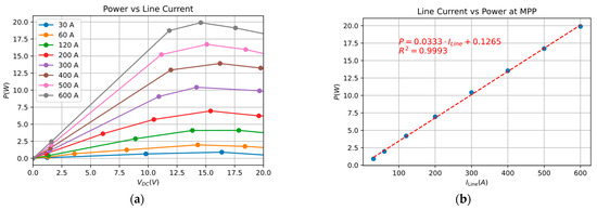
Figure 10.
Power harvested by the MFEH with 50 Hz and 0–600 A primary currents: (a) for different DC voltages; and (b) at maximum power point currents.

Table 2.
Power harvested with MFEH transducer and voltage on DC bus after rectification stage with multiple primary line currents with different loads. Measured using a diode rectifier and a programable DC electronic load.
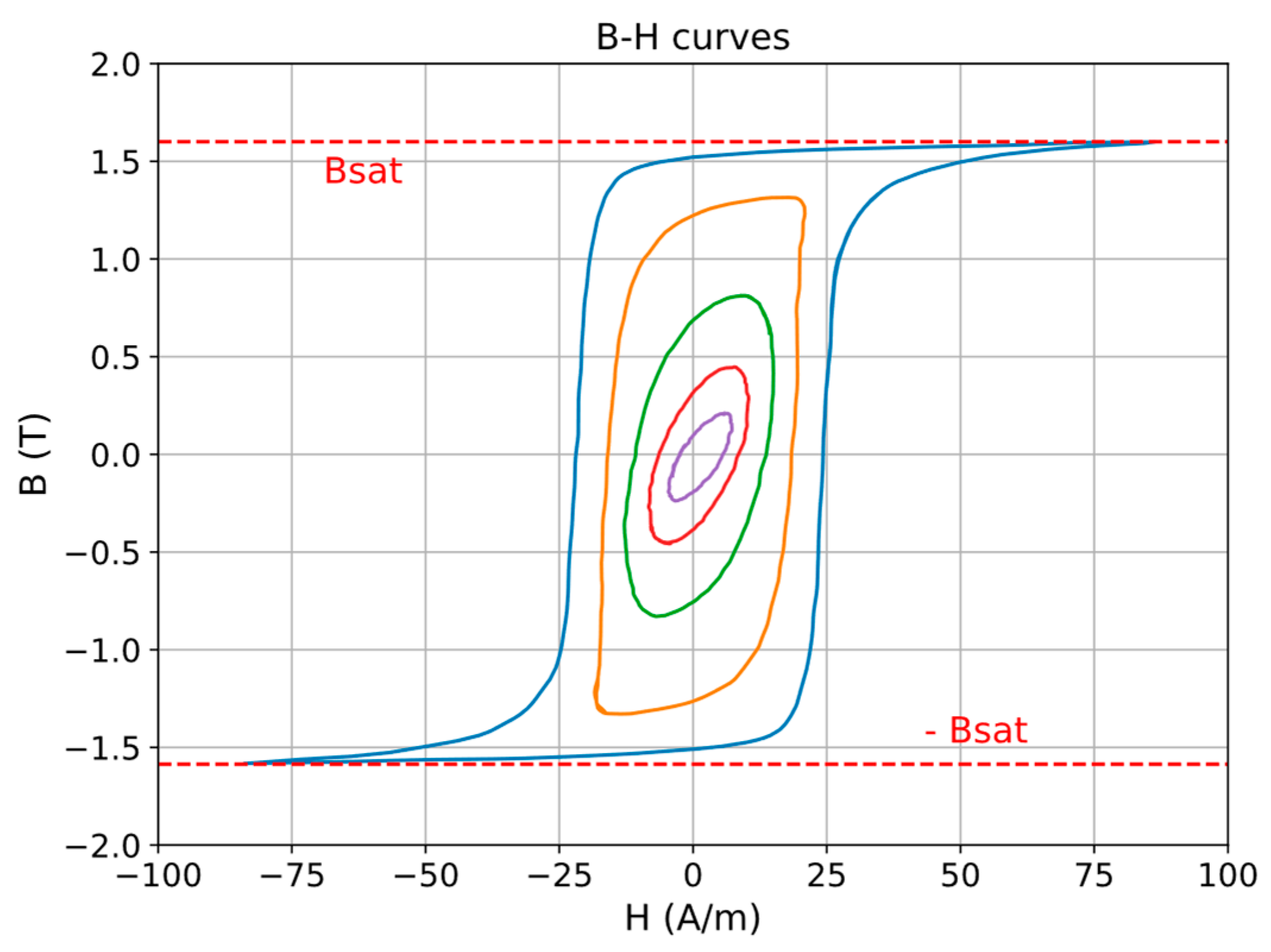
Figure 11 illustrates the specific B-H curve extracted from the ferromagnetic core selected for the proposal. This curve is defined by the following two notable parameters: the permeability which quantifies the ease with which a material is magnetized when exposed to an external magnetic field; and the saturation flux density (Bsat), which represents the maximum amount of magnetic flux that causes the magnetic domains to be fully oriented.
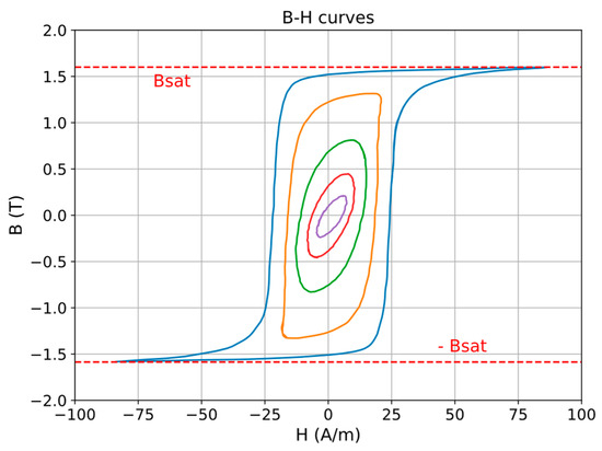
Figure 11.
Family of B-H loops (hysteresis loops) and boundaries regions measured at 50 Hz, for a toroidal sample selected of grain-oriented electrical steel.
5. Results
In order to implement and test the proposed approach, the control loop and data acquisition were programmed within a reference board based on an STM32G4 microcontroller. The power electronic and signal conditioning components associated with the full-bridge were implemented with an expansion board based on N-channel MOSFETs (STL220N6F7) that were modified to meet the requirement of working at 50–60 Hz and provide the current and voltage measurements within the specified range for this application.
In accordance with the specified design parameters, the maximum permissible current in the power line is 600 A, while the transducer turn ratio in the coil limits the current to 1.67 A on the power converter. The low switching frequency and the turn-on soft-switching operation have a negligible impact on power losses, thereby promoting energy efficiency. The MOSFETs selected offer a typical Ron resistance of 1.4 mΩ. In a worst-case scenario where the H-bridge is constantly short-circuiting the transducer, power loss is concentrated on the two bottom MOSFETs, each of which has a loss of 3.89 mW. This can be readily dissipated to the PCB thanks to these losses accounting for 0.5% of the rated power.
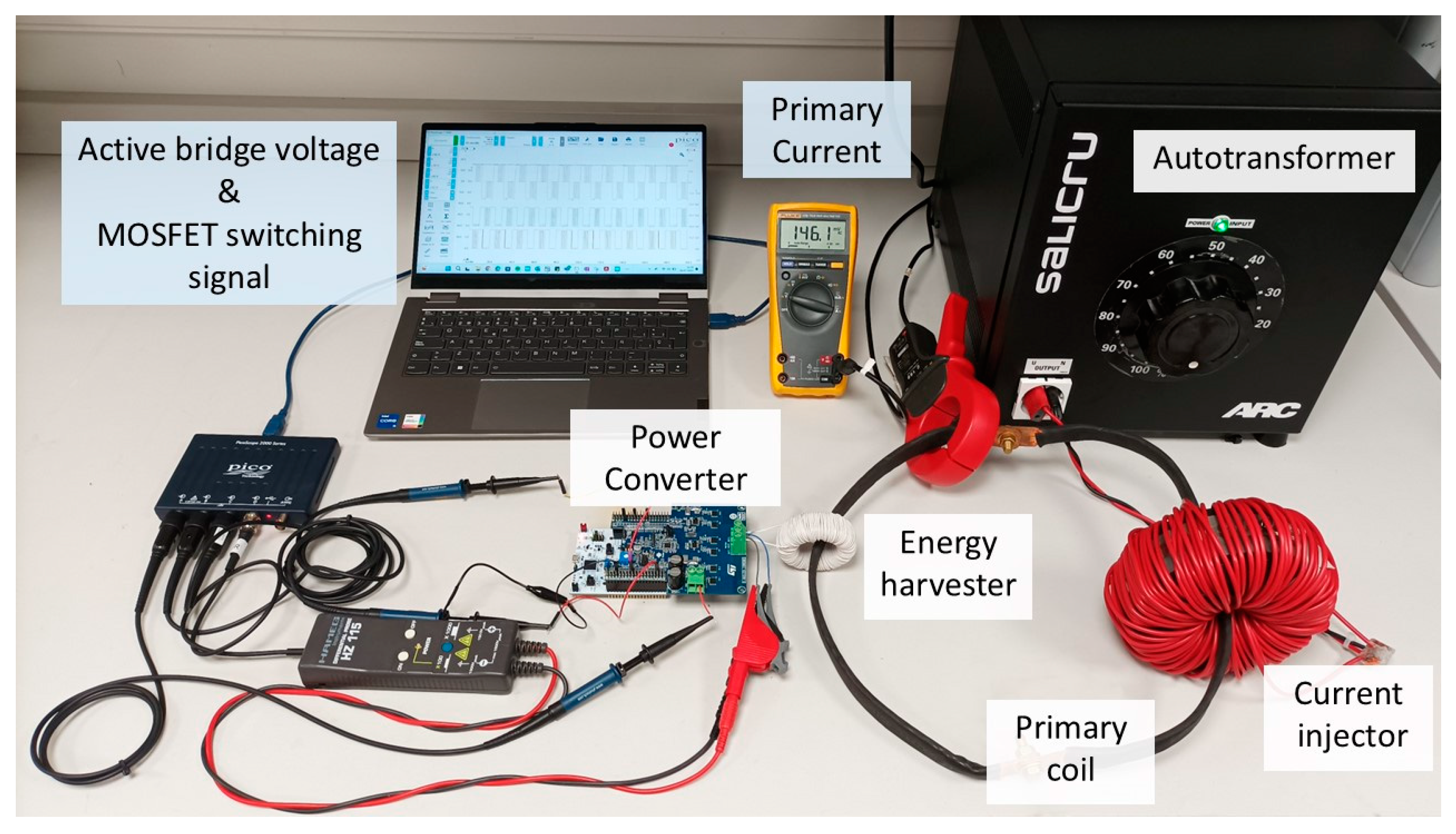
Figure 12 illustrates the prototype installed on the test bench, which is equipped to emulate a power line environment. A 50 Hz alternating magnetic field analogue to a European power line is generated in the primary coil. This magnetic field is manually controlled by an autotransformer to regulate the voltage in the current injector. The energy harvester prototype is connected to the power converter, which is managed by the control algorithm coded into the microcontroller. The transducer harvests energy from the magnetic field and the power stage rectifies the induced AC voltage to convert it to fixed 15 V DC voltage. Finally, a configurable electronic load is added to control the power consumption.
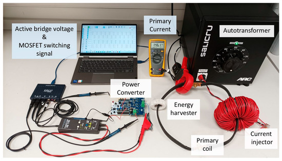
Figure 12.
Laboratory test bench equipped with MFEH consisting of a transducer and a single-stage AC/DC converter connected to an emulated power line.
In order to determine the functionality and performance of the single-stage AC/DC converter with the proposed energy harvester, a series of tests were conducted. To evaluate the functionality, the induced voltage on the transducer, DC bus voltage output, ripple, and MOSFET switching control signals were monitored. Taking the maximum current line under consideration to be 600 A and a fixed 1.5 W load in the DC side, the following notable tests were carried out:
- The primary current is 5% of the maximum power line current (30 A).
- The primary current is 10% of the maximum power line current (60 A).
- The primary current is 50% of the maximum power line current (300 A).
- The primary current is the maximum power line current (600 A).
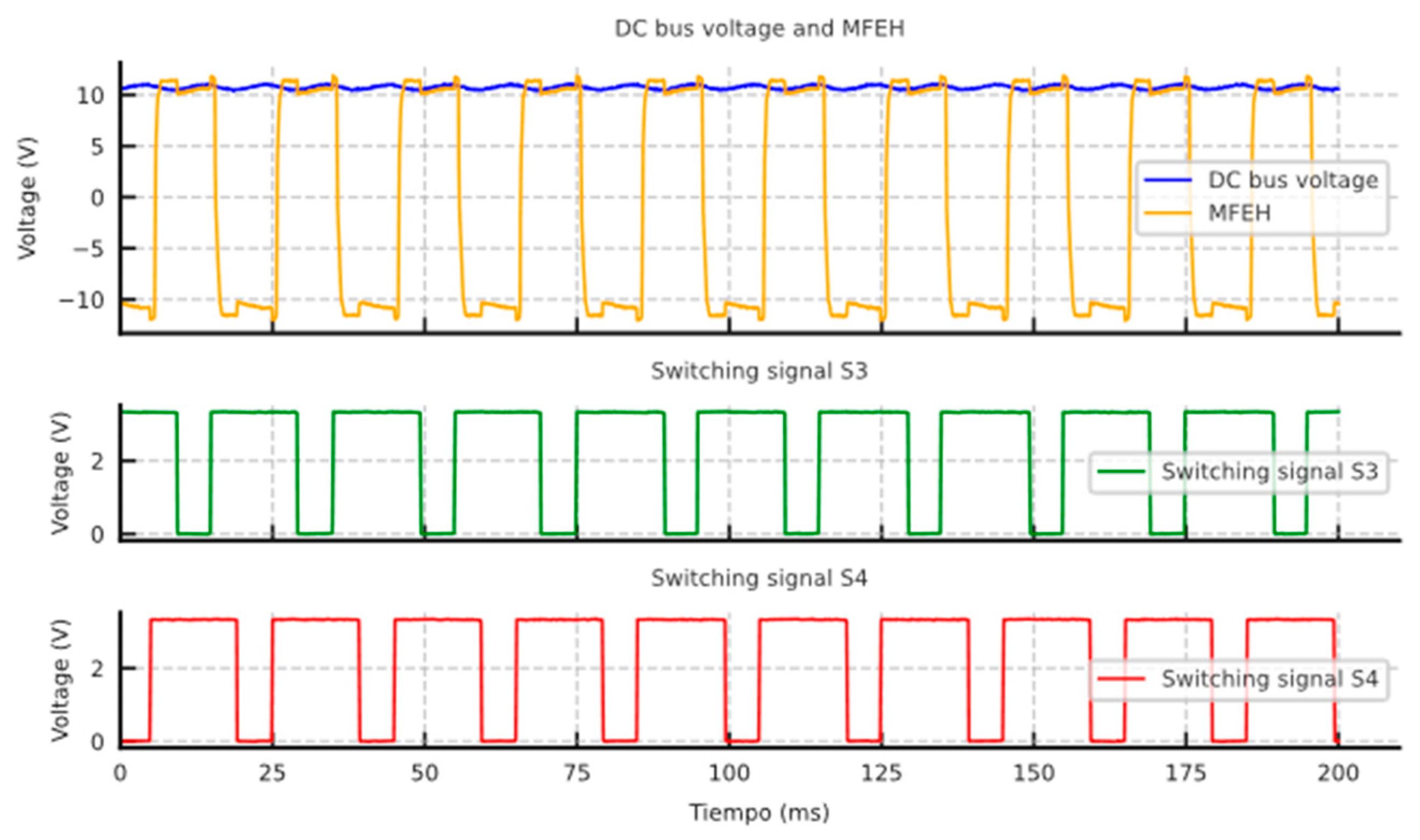
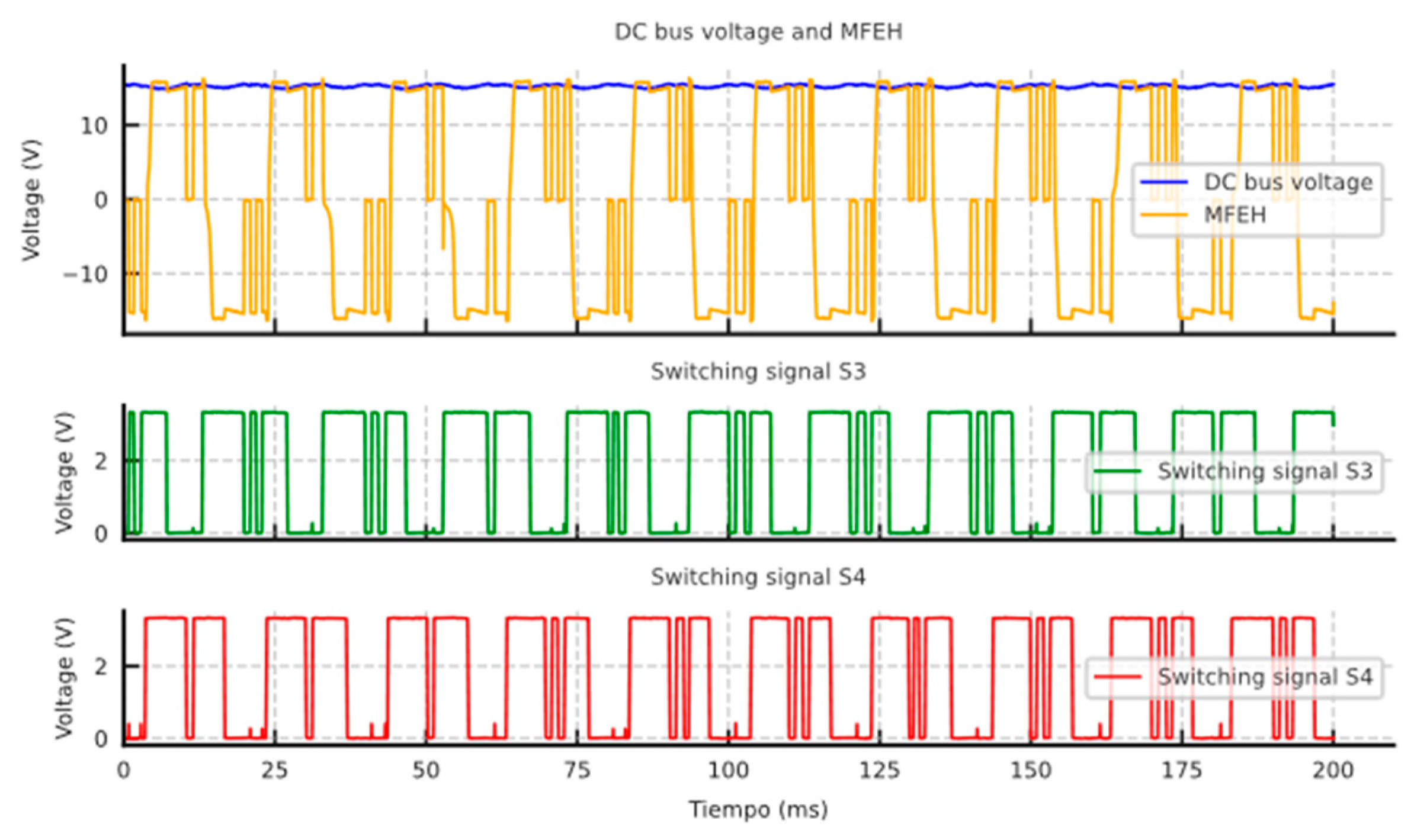
During the first test, the primary current is 5% of the maximum power line current, equivalent to 30 A. As shown in Figure 13, the voltage achieved on the DC bus at this specific point is around 10 V, as the harvested power is insufficient to reach 15 V and continuously provide 1.5 W to the load.
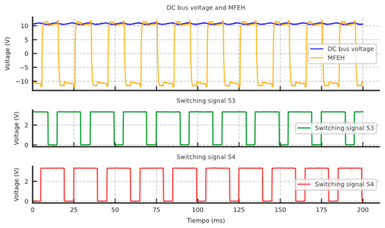
Figure 13.
Laboratory measurements of the induced voltage on the MFEH transducer (yellow), the DC bus voltage (blue) and the MOSFET switching signals of the bottom MOSFETs (red and green, active at 0 V) emulating a current of 5% of the maximum power line current (30 A).
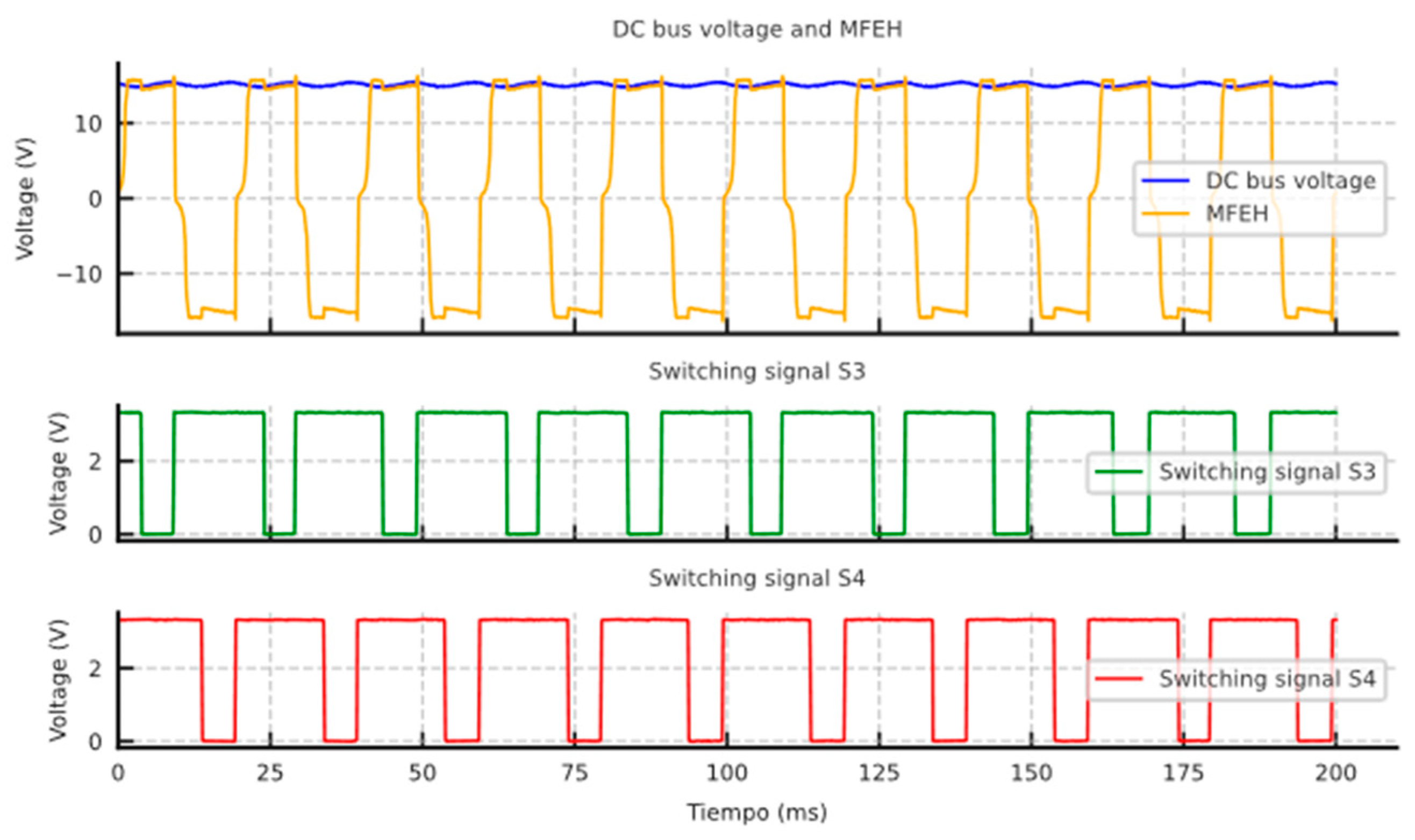
The second test is conducted when the DC bus voltage stabilizes at 15 V, which is observed at a primary coil current of approximately 60 A, equivalent to 10% of the maximum power line current. Under these conditions, the energy harvested from the power line equals the power consumed, enabling a continuous supply of 1.5 W to the load. As shown in Figure 14, the DC bus maintains a stable output of 15 V with minimal ripple, demonstrating the system’s stability.
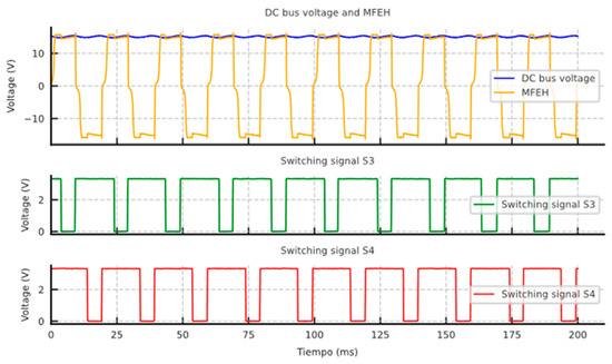
Figure 14.
Laboratory measurements of the induced voltage on the MFEH transducer (yellow), the DC bus voltage (blue) and the MOSFET switching signals of the bottom MOSFETs (red and green, active at 0 V) emulating a current of 10% of the maximum power line current (60 A).
In the third test, the primary current is defined as 50% of the maximum power line current, which is equivalent to 300 A. In scenarios where the harvested power exceeds the load demand, the DC bus voltage regulator plays a critical role in preventing overvoltage conditions by managing the short-circuiting of the transducer. As illustrated in Figure 15, during each half-cycle of the AC-induced voltage, the smoothing capacitor on the DC bus reaches the upper voltage limit within the hysteresis control loop. At this point, a short-circuit is applied to the transducer by activating both bottom MOSFETs. Once the capacitor discharges to the lower voltage limit due to load consumption, the short-circuit is released, restoring normal operation. This mechanism ensures reliable voltage regulation and protects the system from overvoltage conditions.
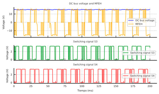
Figure 15.
Laboratory measurements of the induced voltage on the MFEH transducer (yellow), the DC bus voltage (blue) and the MOSFET switching signals of the bottom MOSFETs (red and green, active at 0 V) emulating a current of 50% of the maximum power line current (300 A).
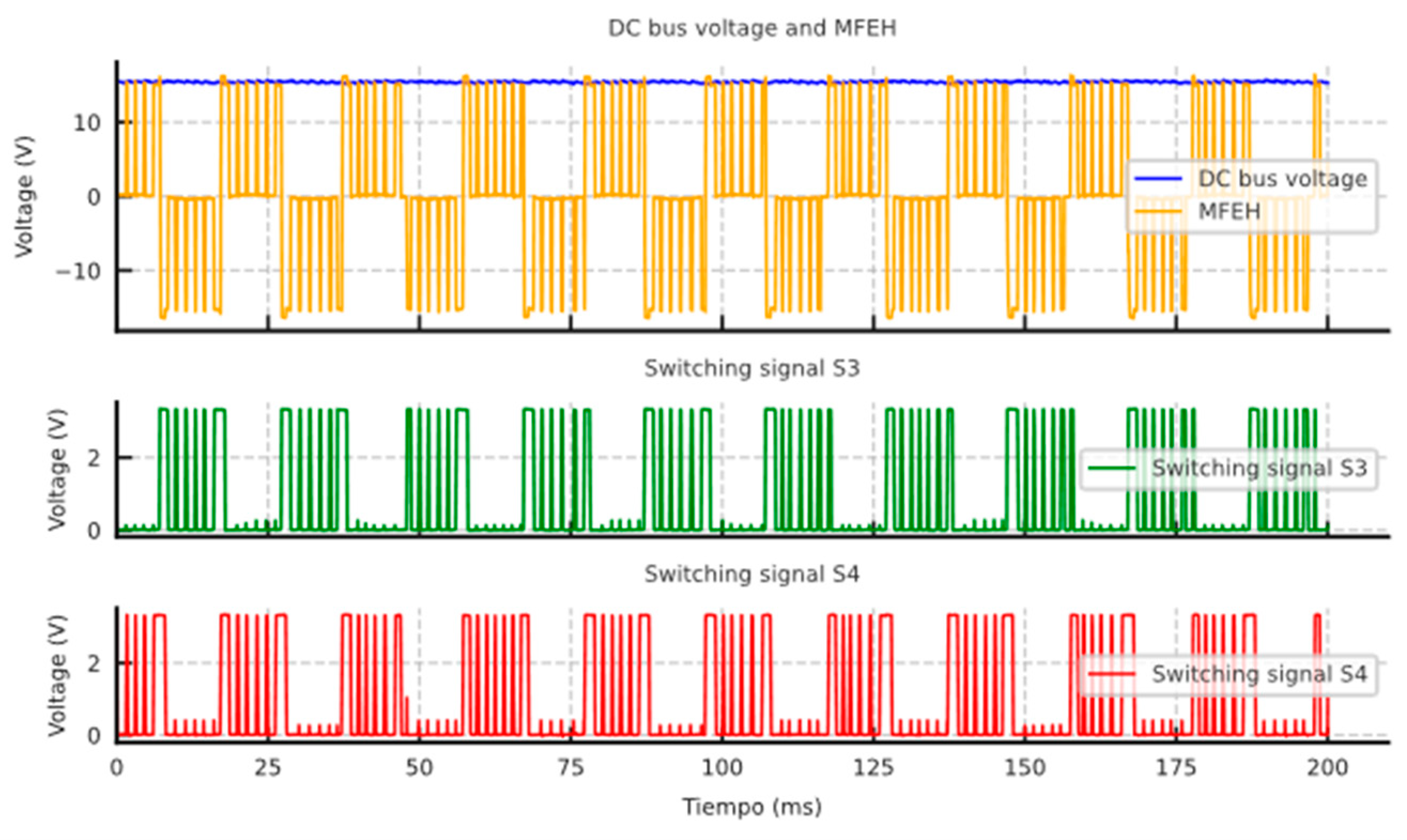
The final test is conducted at the maximum power line current of 600 A. At this current, the harvested power reaches its maximum surplus, significantly exceeding the load requirements. As a result, the DC voltage regulator takes over to manage the short-circuiting of the transducer. In this scenario, the DC bus capacitor charges more rapidly due to the increased power output from the transducer. It is observed that, for the majority of the period during which an alternative voltage is induced on the MFEH, the DC voltage regulator actively short-circuits the transducer. This behavior is depicted in Figure 16, highlighting the regulator’s role in maintaining system stability under these conditions.
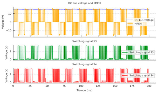
Figure 16.
Laboratory measurements of the induced voltage on the MFEH transducer (yellow), the DC bus voltage (blue) and the MOSFET switching signals of the bottom MOSFETs (red and green, active at 0 V) emulating the maximum power line current (600 A).
The spectral purity of the output signal in each test is approximately 99.99%, with the dominant frequency being 0 Hz and a negligible component of 100 Hz and multiples, attributable to grid frequency rectification. This indicates that the majority of the signal’s energy is concentrated at the DC component.
6. Discussion
This paper presents a single-stage AC/DC power converter and control architecture designed for a non-intrusive MFEH. This power converter is composed of a full-bridge MOSFET stage that provides active rectification while regulating the output voltage. The energy harvester is based on a current transformer that uses alternating current-carrying components to support the operation of self-powered smart grid IoT devices.
This research introduces a new approach that contributes to the development of compact energy harvesters suitable for self-powered smart grid IoT devices. The key contributions of this research include the development of a single-stage AC-to-DC power electronic converter designed to reduce components and losses in energy conversion process. Additionally, the design and implementation of a control architecture for voltage regulation and active rectification has been proposed, enhancing the performance of the proposed power stage and the design of the energy harvesting system tailored to achieve an extended and efficient range.
In order to provide further validation of the advantages of the proposed single-stage power converter, Table 3 provides a comparison between the present design and existing multistage converter topologies discussed in the state of the art. This comparison highlights the differences in the number of stages and component count in multistage designs that typically require separate rectification and regulation stages, generally resulting in greater complexity and lower energy density in power conversion. The proposed single-stage approach integrates active rectification that minimizes energy losses, thereby improving thermal management in power electronics and voltage regulation in a compact power stage. On the other hand, in contrast to battery-powered devices, the proposed solution requires a minimum current on the line to power the load.

Table 3.
Comparative comparison of the number of stages, semiconductor and passive elements in the proposed single-stage converter and existing multistage designs.
The results of this research indicate that MFEH technology is an effective method for powering IoT sensors for integration into smart grids, providing an alternative to the use of conventional batteries. Further research is required to integrate the MFEH and power electronics into a field device. In addition, a long-term demonstrator in a real-world environment is necessary to gather further insights into potential contingencies affecting electrical infrastructure. These include overcurrent events, unexpected disconnections, lightning strikes, extremes of temperature, and high humidity. Other challenges that must be addressed include integrating with existing infrastructure to ensure compatibility, designing for electromagnetic interference and harmonic distortions, and ensuring easy deployment in remote locations. Finally, a cost–benefit analysis for scalability and long-term durability must be conducted. These scenarios would help evaluate the resilience and reliability of the proposed system under diverse operating conditions. Despite the negligible influence of a single device on additional impedance and harmonics due to converter switching in the power line, further research is required to assess the impact of MFEH in a large-scale deployment of these technologies.
Author Contributions
Investigation, A.-M.M.-G., M.M.-M. and J.B.-F.; Writing—Original Draft, A.-M.M.-G.; Writing—Review and Editing, J.B.-F., M.M.-M. and J.-F.S.-O. All authors have read and agreed to the published version of the manuscript.
Funding
This research received no external funding.
Data Availability Statement
The original contributions presented in this study are included in the article. Further inquiries can be directed to the corresponding author.
Conflicts of Interest
The authors declare no conflicts of interest.
References
- European Union. A Strategic Long-Term Vision for a Prosperus, Moder, Competitive and Climate-Neutral EU Econonomy; European Union: Luxembourg, Belgium, 2019. [Google Scholar]
- Borroy Vicente, S.; Fernández, G.; Galan, N.; Llombart Estopiñán, A.; Salani, M.; Derboni, M.; Giuffrida, V.; Hernández-Callejo, L. Assessment of the Technical Impacts of Electric Vehicle Penetration in Distribution Networks: A Focus on System Management Strategies Integrating Sustainable Local Energy Communities. Sustainability 2024, 16, 6464. [Google Scholar] [CrossRef]
- Yang, W.; Wang, H.; Wang, Z.; Fu, X.; Ma, P.; Deng, Z.; Yang, Z. Optimization Strategy of Electric Vehicles Charging Path Based on “Traffic-Price-Distribution” Mode. Energies 2020, 13, 3208. [Google Scholar] [CrossRef]
- Agazar, M.; D’Avanzo, G.; Frigo, G.; Giordano, D.; Iodice, C.; Letizia, P.S.; Luiso, M.; Mariscotti, A.; Mingotti, A.; Munoz, F.; et al. Power Grids and Instrument Transformers up to 150 KHz: A Review of Literature and Standards. Sensors 2024, 24, 4148. [Google Scholar] [CrossRef] [PubMed]
- Osheba, M.S.; Aboutaleb, A.M.; Desmet, J.; Knockaert, J. The Impact of Grid Distortion on the Power Conversion Harmonics of AC/DC Converters in the Supraharmonic Range. Electronics 2024, 13, 2244. [Google Scholar] [CrossRef]
- Liang, D.; Ge, S.; Guo, H.; Wang, Y.; Liang, Z.; Chen, C. Monitoring Power Line Faults Using Impedance Estimation Algorithms in Power Line Communication Equipment. In Proceedings of the 2020 10th International Conference on Power and Energy Systems (ICPES), Chengdu, China, 25–27 December 2020; pp. 404–408. [Google Scholar]
- Izmirlioglu, Y.; Pham, L.; Son, T.C.; Pontelli, E. A Survey of Multi-Agent Systems for Smartgrids. Energies 2024, 17, 3620. [Google Scholar] [CrossRef]
- Beheshti Asl, M.; Fofana, I.; Meghnefi, F. Review of Various Sensor Technologies in Monitoring the Condition of Power Transformers. Energies 2024, 17, 3533. [Google Scholar] [CrossRef]
- Masood, Z.; Ardiansyah; Choi, Y. Energy-Efficient Optimal Power Allocation for Swipt Based Iot-Enabled Smart Meter. Sensors 2021, 21, 7857. [Google Scholar] [CrossRef] [PubMed]
- Kakimoto, Y.; Yoshikawa, H.; Jogo, T.; Wakisaka, T.; Kozako, M.; Hikita, M.; Sato, H.; Soeda, M.; Tagashira, H. Application of Novel Online Partial Discharge Monitoring System Using Power Line Communication to Noise and PD Source Discrimination. In Proceedings of the 2020 8th International Conference on Condition Monitoring and Diagnosis (CMD), Phuket, Thailand, 25–28 October 2020; pp. 130–132. [Google Scholar]
- Alhanaf, A.S.; Balik, H.H.; Farsadi, M. Intelligent Fault Detection and Classification Schemes for Smart Grids Based on Deep Neural Networks. Energies 2023, 16, 7680. [Google Scholar] [CrossRef]
- Al-Mashhadani, S.W.T.; Kurnaz, S. A Novel Function of a Research Process Based on a Power Internet of Things Architecture Intended for Smart Grid Demand Schemes. Appl. Sci. 2024, 14, 5799. [Google Scholar] [CrossRef]
- Ji, K.; Zhang, L.; Han, J.; Tang, H.; Ma, X.; Li, K. Integrated Monitoring Technology for Tension and Inclination of Overhead Transmission Lines Based on Fiber Bragg Grating. In Proceedings of the 2023 3rd International Conference on Electrical Engineering and Mechatronics Technology, ICEEMT 2023, Nanjing, China, 21–23 July 2023; Institute of Electrical and Electronics Engineers Inc.: Piscataway, NJ, USA, 2023; pp. 81–85. [Google Scholar]
- Aldin, H.N.S.; Ghods, M.R.; Nayebipour, F.; Torshiz, M.N. A Comprehensive Review of Energy Harvesting and Routing Strategies for IoT Sensors Sustainability and Communication Technology. Sens. Int. 2024, 5, 100258. [Google Scholar] [CrossRef]
- Banotra, A.; Ghose, S.; Mishra, D.; Modem, S. Energy Harvesting in Self-Sustainable IoT Devices and Applications Based on Cross-Layer Architecture Design: A Survey. Comput. Netw. 2023, 236, 110011. [Google Scholar] [CrossRef]
- Repuri, R.K.; Darsy, J.P. Energy-Efficient LoRa Routing for Smart Grids. Sensors 2023, 23, 3072. [Google Scholar] [CrossRef] [PubMed]
- Sarker, M.R.; Riaz, A.; Lipu, M.S.H.; Md Saad, M.H.; Ahmad, M.N.; Kadir, R.A.; Olazagoitia, J.L. Micro Energy Harvesting for IoT Platform: Review Analysis toward Future Research Opportunities. Heliyon 2024, 10, e27778. [Google Scholar] [CrossRef]
- Cao, K.; Liu, Y.; Meng, G.; Sun, Q. An Overview on Edge Computing Research. IEEE Access 2020, 8, 85714–85728. [Google Scholar] [CrossRef]
- Wu, J.; Du, W.; Wang, J.; Yang, G.; Zhao, Y. Application of Power Internet of Things in Online Monitoring of Transmission Lines. In Proceedings of the 2023 Smart City Challenges and Outcomes for Urban Transformation, SCOUT 2023, Singapore, 29–30 July 2023; Institute of Electrical and Electronics Engineers Inc.: Piscataway, NJ, USA, 2023; pp. 19–23. [Google Scholar]
- Citroni, R.; Mangini, F.; Frezza, F. Efficient Integration of Ultra-Low Power Techniques and Energy Harvesting in Self-Sufficient Devices: A Comprehensive Overview of Current Progress and Future Directions. Sensors 2024, 24, 4471. [Google Scholar] [CrossRef] [PubMed]
- Zeng, P.; Li, C.; Huang, H.; Liu, H.; Gao, Z. Design and Research of a Self-Powered Temperature Measurement System for Transmission Line Condition Monitoring. In Proceedings of the IEEE 6th Information Technology and Mechatronics Engineering Conference, ITOEC 2022, Chongqing, China, 4–6 March 2022; Institute of Electrical and Electronics Engineers Inc.: Piscataway, NJ, USA, 2022; pp. 889–894. [Google Scholar]
- Shi, Y.; Cui, X.; Qi, L.; Zhang, X.; Li, X.; Shen, H. A Novel Energy Harvesting Method for Online Monitoring Sensors in HVdc Overhead Line. IEEE Trans. Ind. Electron. 2023, 70, 2139–2143. [Google Scholar] [CrossRef]
- Bendík, J.; Cenký, M.; Hromkovič, O. Energy Harvesting Device for Smart Monitoring of MV Overhead Power Lines—Theoretical Concept and Experimental Construction. Sensors 2023, 23, 7538. [Google Scholar] [CrossRef] [PubMed]
- Liu, Y.; Riba, J.R.; Moreno-Eguilaz, M. Energy Balance of Wireless Sensor Nodes Based on Bluetooth Low Energy and Thermoelectric Energy Harvesting. Sensors 2023, 23, 1480. [Google Scholar] [CrossRef]
- Li, H.; Liu, K.; Deng, J. Modeling and Evaluation of a Multi-Stable Hybrid Energy Harvester. Vibration 2024, 7, 662–686. [Google Scholar] [CrossRef]
- Lian, Q.; Han, P.; Mei, N. A Review of Converter Circuits for Ambient Micro Energy Harvesting. Micromachines 2022, 13, 2222. [Google Scholar] [CrossRef]
- Tang, N.; Huang, M.; Sheng, C.; Lu, Q.; Huang, H.; Lee, C.K. Lee A Power Supply Method for On-Line Monitoring Instruments Based on Insulation String Embedded Resonators in Domino For. In Proceedings of the 2018 International Conference on Power System Technology (POWERCON), Guangzhou, China, 6–8 November 2018; pp. 4071–4076. [Google Scholar]
- Gao, M.; Yi, L.; Moon, J. Enabling Multiple Harvesting Windows in Magnetic Energy Harvesting via Reverse Flux Desaturation. IEEE J. Emerg. Sel. Top. Power Electron. 2024, 12, 2517–2530. [Google Scholar] [CrossRef]
- Zhuang, Y.; Xu, C.; Song, C.; Chen, A.; Lee, W.; Huang, Y.; Zhou, J. Improving Current Transformer-Based Energy Extraction from Ac Power Lines by Manipulating Magnetic Field. IEEE Trans. Ind. Electron. 2020, 67, 9471–9479. [Google Scholar] [CrossRef]
- Kuang, Y.; Chew, Z.J.; Ruan, T.; Zhu, M. Magnetic Field Energy Harvesting from Current-Carrying Structures: Electromagnetic-Circuit Coupled Model, Validation and Application. IEEE Access 2021, 9, 46280–46291. [Google Scholar] [CrossRef]
- Huh, S.; Koo, J., II; Jeong, O.; Ahn, S. Maximizing Output Power Using a Magnetic Energy Harvesting System Considering the Relationship Between Harvesting Time and Induced Voltage Due to a Change of Airgap. IEEE Access 2024, 12, 5947–5959. [Google Scholar] [CrossRef]
- Wang, W.; Huang, X.; Tan, L.; Guo, J.; Liu, H. Optimization Design of an Inductive Energy Harvesting Device Forwireless Power Supply System Overhead High-Voltage Power Lines. Energies 2016, 9, 242. [Google Scholar] [CrossRef]
- Wu, T.; Ju, D.; Wang, C.; Huang, H.; Li, C.; Wu, C.; Wang, C.; Liu, H.; Jiang, X.; Ye, K.; et al. Ferrite Materials with High Saturation Magnetic Induction Intensity and High Permeability for Magnetic Field Energy Harvesting: Magnetization Mechanism and Brillouin Function Temperature Characteristics. J. Alloys Compd. 2023, 933, 167654. [Google Scholar] [CrossRef]
- Liu, L.; Wen, X.; Shi, R.; Li, P.; Wen, Y.; Han, T. High-Efficiency Magnetic Field Energy Harvesting from a Three-Core Cable. Sens. Actuators A Phys. 2023, 360, 114501. [Google Scholar] [CrossRef]
- Kuang, Y.; Chew, Z.J.; Ruan, T.; Lane, T.; Allen, B.; Nayar, B.; Zhu, M. Magnetic Field Energy Harvesting from the Traction Return Current in Rail Tracks. Appl. Energy 2021, 292, 116911. [Google Scholar] [CrossRef]
- Muñoz-Gómez, A.M.; Marredo-Píriz, J.M.; Ballestín-Fuertes, J.; Sanz-Osorio, J.F. A Novel Charging Station on Overhead Power Lines for Autonomous Unmanned Drones. Appl. Sci. 2023, 13, 10175. [Google Scholar] [CrossRef]
- Yang, F.; Du, L.; Yu, H.; Huang, P. Magnetic and Electric Energy Harvesting Technologies in Power Grids: A Review. Sensors 2020, 20, 1496. [Google Scholar] [CrossRef] [PubMed]
- Muñoz-Gómez, A.M.; Ballestín-Fuertes, J.; Sanz-Osorio, J.F. A High Efficiency Battery Charger with Maximum Power Point Tracking for Magnetic Energy Harvesters. In Proceedings of the PCIM Europe Conference Proceedings, Mesago PCIM GmbH, Nuremberg, Germany, 11–13 June 2024; Volume 2024, pp. 625–634. [Google Scholar]
- Erdem, H.E.; Gungor, V.C. On the Lifetime Analysis of Energy Harvesting Sensor Nodes in Smart Grid Environments. Ad Hoc Netw. 2018, 75–76, 98–105. [Google Scholar] [CrossRef]
- Sanislav, T.; Mois, G.D.; Zeadally, S.; Folea, S.C. Energy Harvesting Techniques for Internet of Things (IoT). IEEE Access 2021, 9, 39530–39549. [Google Scholar] [CrossRef]
- Muñoz, A.M.; Muñoz, J.; Granado, J.; Sanz, J.F. Wireless Self-Powered Monitoring System for Underground Cable Joints: A Real Use-Case. In Proceedings of the 27th International Conference on Electricity Distribution (CIRED 2023), Rome, Italy, 12–15 June 2023; Volume 2023, pp. 2124–2128. [Google Scholar]
- Enayati, J.; Asef, P. Review and Analysis of Magnetic Energy Harvesters: A Case Study for Vehicular Applications. IEEE Access 2022, 10, 79444–79457. [Google Scholar] [CrossRef]
- Ahmed, M.; Genevey, S.; Ali, M.; Savaria, Y.; Audet, Y. Recent Start-Up Techniques Intended for TEG Energy Harvesting: A Review. IEEE Access 2024, 12, 34116–34130. [Google Scholar] [CrossRef]
- Luo, P.; Peng, D.; Wang, Y.; Zheng, X. Review of Solar Energy Harvesting for IoT Applications. In Proceedings of the 2018 IEEE Asia Pacific Conference on Circuits and Systems (APCCAS), Chengdu, China, 26–30 October 2018; pp. 512–515. [Google Scholar]
- Hassani, V.; Tjahjowidodo, T.; Do, T.N. A Survey on Hysteresis Modeling, Identification and Control. Mech. Syst. Signal Process. 2014, 49, 209–233. [Google Scholar] [CrossRef]
- Liu, Z.; Li, Y.; Yang, H.; Duan, N.; He, Z. An Accurate Model of Magnetic Energy Harvester in the Saturated Region for Harvesting Maximum Power: Analysis, Design, and Experimental Verification. IEEE Trans. Ind. Electron. 2023, 70, 276–285. [Google Scholar] [CrossRef]
Disclaimer/Publisher’s Note: The statements, opinions and data contained in all publications are solely those of the individual author(s) and contributor(s) and not of MDPI and/or the editor(s). MDPI and/or the editor(s) disclaim responsibility for any injury to people or property resulting from any ideas, methods, instructions or products referred to in the content. |
© 2025 by the authors. Licensee MDPI, Basel, Switzerland. This article is an open access article distributed under the terms and conditions of the Creative Commons Attribution (CC BY) license (https://creativecommons.org/licenses/by/4.0/).

