Article

Optimization of Active Disturbance Rejection Control System for Vehicle Servo Platform Based on Artificial Intelligence Algorithm

by
Fei Yang
1,2,*,
Xiaopeng Su
3 and
Xuemei Ren
2
1
Intelligent Control Algorithm Design Room, Chongqing Changan Wangjiang Industrial Group Co., Ltd., Chongqing 401120, China
2
School of Automation, Beijing Institute of Technology, Beijing 100086, China
3
Science and Technology Development Department, Chongqing Changan Wangjiang Industrial Group Co., Ltd., Chongqing 401120, China
*
Author to whom correspondence should be addressed.
Electronics 2025, 14(4), 752; https://doi.org/10.3390/electronics14040752
Submission received: 2 January 2025 / Revised: 8 February 2025 / Accepted: 10 February 2025 / Published: 14 February 2025
(This article belongs to the Section Electrical and Autonomous Vehicles)

Abstract

:
The rapid growth of automotive intelligence and automation technology has made it difficult for traditional in-vehicle servo systems to satisfy the demands of modern intelligent systems when facing complex problems such as external disturbances, nonlinearity, and parameter uncertainty. To improve the anti-interference ability and control accuracy of the system, this study proposes a joint control method of electronic mechanical braking control combined with the anti-lock braking system. This method has developed a new type of actuator in the electronic mechanical brake control system and introduced a particle swarm optimization algorithm to optimize the parameters of the self-disturbance rejection control system. At the same time, it combines an adaptive inversion algorithm to optimize the anti-lock braking system. The results indicated that the speed variation of the developed actuator and the actual signal completely stopped at 1.9 s. During speed control and deceleration, the actuator could respond quickly and accurately to control commands as expected. On an asphalt pavement, the maximum slip rate error of the optimized control method was 0.0428, while the original control method was 0.0492. The optimized method reduced the maximum error by about 12.9%. On icy and snowy roads, the maximum error of the optimization method was 0.0632, significantly lower than the original method’s 0.1266. The optimization method could significantly reduce slip rate fluctuations under extreme road conditions. The proposed method can significantly improve the control performance of the vehicle-mounted servo platform, reduce the sensitivity of the system to external disturbances, and has high practical value.

1. Introduction

With the continuous improvement of intelligent transportation, autonomous driving, and vehicle control system technology, the Vehicle Servo System (VSS) platform is increasingly vital in intelligent driving, automatic parking, and robot control [1]. As a type of VSS, the Electro-Mechanical Brake (EMB) system directly drives the brake caliper through an electric motor to control the braking force. It has the advantages of a fast response speed, compact structure, and easy maintenance. However, an EMB faces multiple challenges in practical applications, such as external disturbances, changes in system parameters, and complex environmental factors. In complex driving environments, various interference sources, such as road bumps, wind speed changes, and vehicle load fluctuations, can significantly affect the braking performance of EMB systems, leading to a decrease in control accuracy and response speed. Conventional methods, such as PID control and robust control, can, to a certain extent, ensure fundamental performance. However, they frequently encounter challenges in meeting the demands of real-time accuracy when confronted with complex operating conditions characterized by large-scale nonlinearity, time-varying disturbances, and high dynamic characteristics [2]. Active Disturbance Rejection Control (ADRC), as a novel control method, has received widespread attention for its ability to directly handle system disturbances without the need for an accurate model. It has been demonstrated that alterations in factors such as the operating environment, temperature, humidity, load, and time of the vehicle can result in substantial changes to the dynamic characteristics and control parameters of the EMB system. This phenomenon can impede the adaptability of the preset control parameters to the evolving working conditions, consequently leading to a decline in system performance. Although ADRC can effectively suppress external disturbances under certain conditions, its control accuracy and robustness are still limited by factors such as parameter selection and disturbance estimation accuracy [3]. By utilizing Artificial Intelligence (AI) algorithms for system modeling, parameter optimization, and disturbance estimation, the adaptability and accuracy of the system can be effectively improved. For example, Nguyen et al. adjusted the PID controller parameters and their optimal range through fuzzy algorithm and genetic algorithm for the adaptability and stability of automotive electric steering systems. The results indicated that the method was effective [4]. Particle Swarm Optimization (PSO), as a type of AI algorithm, simulates the behavior of particle swarm in nature and utilizes the collaboration and information sharing among individuals in the group to find the optima [5].
The EMB system can be combined with different control methods and algorithms to effectively improve the stability, precision, and reliability of the system. Wng et al. combined the EMB actuator’s full braking and three-loop PID control to ensure the heavy braking load of autonomous vehicles, avoiding an uneven braking force and achieving tracking. The prediction error of this method was less than 10% [6]. Song et al. utilized two Electronic Control Units (ECUs) and a dual winding motor to achieve a tooth modulation effect for vehicle redundancy. This method had practicality [7]. Zhou et al. introduced fuzzy regenerative braking control into the EMB system model for the regenerative braking of electric vehicles and improved it by combining it with the NSGA-II algorithm. This method had good stability [8]. Xu et al. developed a switching Extended State Observer (ESO), considering an equivalent gain for fast force estimation to improve the performance of the EMB. This method had good accuracy [9]. Zhao et al. constructed a nonlinear mathematical model of the EMB system and an enhanced ESO to improve sensor reliability to enhance its performance, which was effective [10]. Wng et al. introduced ADRC in differential drive assist steering to improve the road sensitivity and tracking accuracy, and combined it with a simulated annealing algorithm to optimize the controller parameters offline. The results indicated that this method had good control performance [11].
Some researchers have significantly improved the performance of the ADRC system by combining advanced control theory and technology to optimize it. Zhao et al. optimized ADRC by combining brake dead time compensation and an adaptive LuGre friction model to improve the accuracy and speed of the pressure response execution, which is feasible [12]. Jin et al. proposed a second-order linear ADRC controller by combining the integrator chain and tuning control to improve the controller stability and achieve the expected frequency response. This controller had robustness [13]. Liu et al. proposed an ADRC cascade active suppression control strategy based on radial basis function neural networks for the high-voltage control problem of the system, to avoid coupling interference. This method had good anti-interference performance [14]. Safiullah et al. proposed a second-order active ADRC to reduce the error and estimation performance uncertainty to simultaneously control multiple modules of the system, which performed well [15]. Madonski et al. designed a structure for linear ADRC by combining the output and error to build modules to enhance the efficient control of ADRC. This design had applicability [16].
In summary, both the EMB system and ADRC have achieved good results in their respective application fields. However, facing complex working conditions, the system still has the problem of low robustness and an anti-interference ability to external disturbances. The current control methods perform poorly in terms of multi-system coordination and real-time performance when facing the joint operation of vehicle anti-lock braking systems (ABSs) and EMB systems. Therefore, this study optimizes the EMB system through ADRC and PSO algorithms to improve the system performance. At the same time, a control method that adapts to complex working conditions in conjunction with the ABS of the vehicle is designed to improve the real-time performance and stability of the system. This study aims to further improve the control performance of the VSS platform, and enhance the system’s robustness and anti-interference ability to external disturbances.
The paper mainly consists of four sections. Section 1 introduces the background and current status of the research. At the same time, the EMB system and advanced control methods are mentioned. Section 2 is a joint control system based on optimized ADRC. Section 2.1 introduces the EMB actuator modeling. Section 2.2 is about the optimization method for ADRC clamping force control introducing the PSO algorithm. Section 2.3 is a joint control method for steering and braking. Section 3 presents the results of the study. Section 3.1 contains the EMB control test results. Section 3.2 is an analysis of ABS control effects. Section 4 presents the conclusion of the VSS system using the joint control method.

2. Methods and Materials

This study first builds a new EMB actuator in the EMB system and then introduces the PSO algorithm to achieve ADRC clamping force control optimization. Meanwhile, a joint control method for steering and braking is proposed to cope with vehicle control in different scenarios.

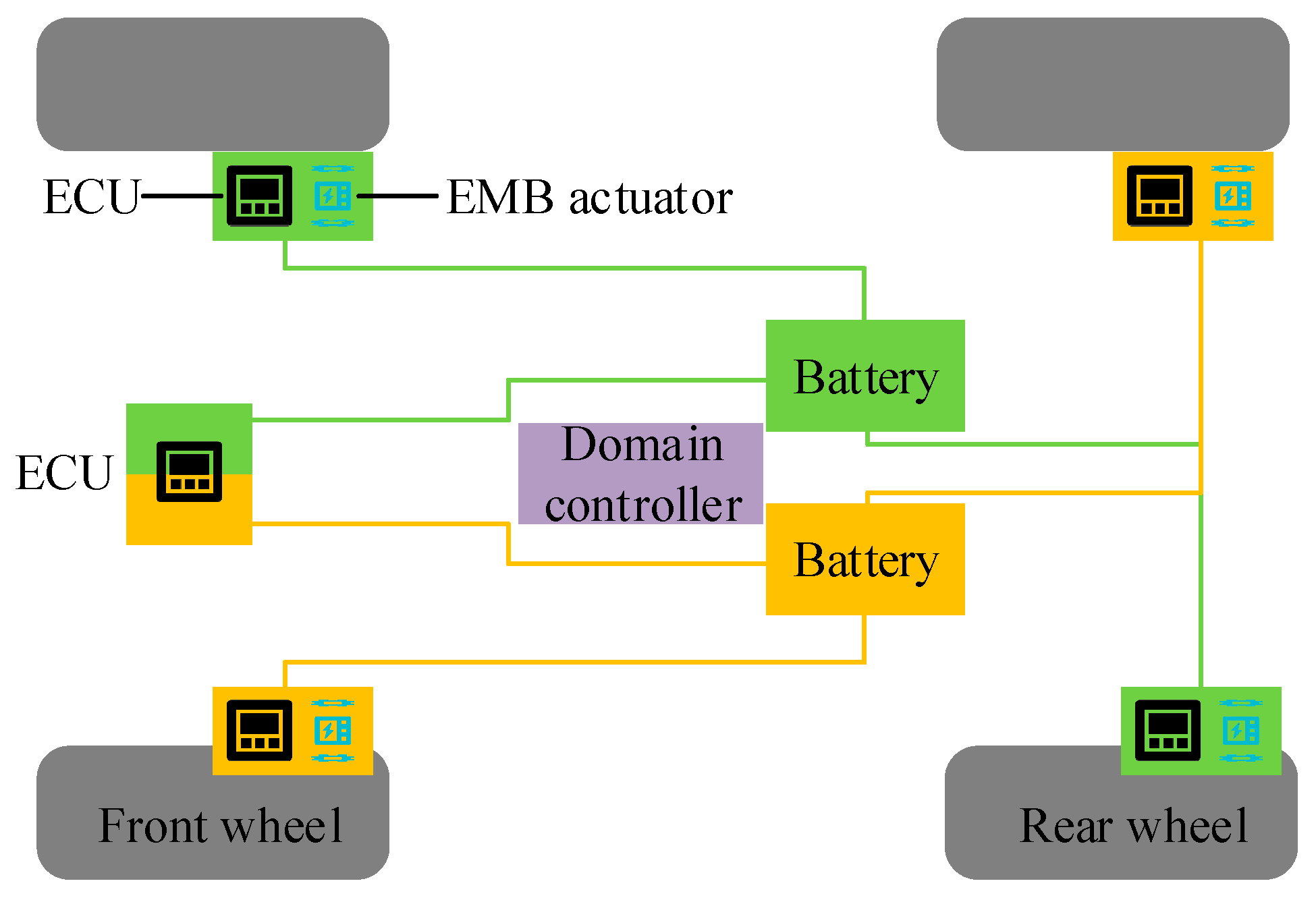
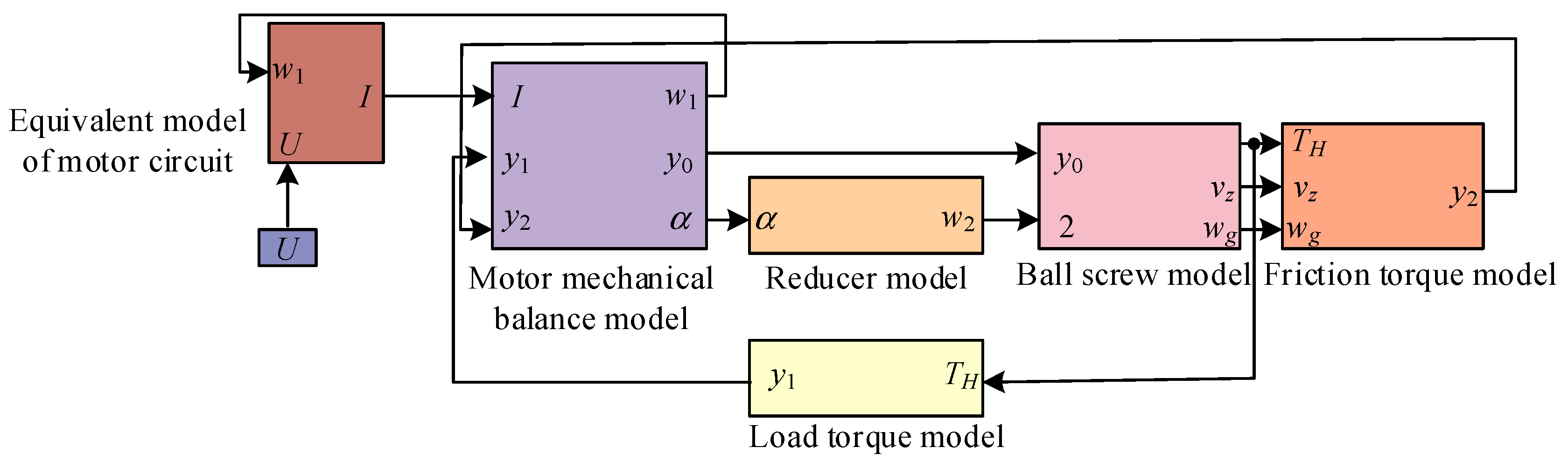
2.1. EMB Actuator Modeling

Due to the strong coupling, time-varying, and other nonlinear characteristics of EMB systems, to ensure the real-time stability of the system, this study designs a prototype EMB actuator and proposes relevant simulation models. The EMB system structure and working mechanism are shown in Figure 1.
In Figure 1, the EMB system mainly consists of an EMB controller, EMB actuator, wheel brake module, ECU, and power supply. The EMB actuator consists of a driving motor, a deceleration and torque-increasing device, and a motion conversion mechanism. These components work together to precisely control the rotation of the motor through the ECU, converting rotational motion into translational motion and driving the brake disc pad to generate braking force. The EMB controller is the core part of the EMB system, responsible for receiving signals, determining the driver’s intention, and outputting brake commands to the brake controller [17]. The motion conversion mechanism is responsible for converting rotational motion into translational motion, driving the brake disc pad to generate braking force. The wheel brake module consists of brake actuators, brake controllers, mechanical transmission mechanisms, and sensors. The brake pedal module includes brake pedals, pedal simulators, displacement/pressure sensors, etc. The communication network coordinates the entire braking system and is responsible for sending various signals to designated areas. The power supply provides energy for the entire braking system. These components work together to provide fast and precise braking response and support advanced vehicle control functions and energy recovery. The composition of the EMB actuator model constructed is shown in Figure 2.
In Figure 2, the model of the actuator includes the equivalent model of the motor circuit, the mechanical balance model of the motor, the reducer model, the ball screw model, the friction torque model, and the load torque model. The equivalent model of the motor circuit outputs the armature current I and motor angular velocity w 1 to the mechanical balance model of the motor. The relevant motor angle and reducer angle in the reducer model are α and w 2 . The electromagnetic torque y 0 , load torque y 1 , and friction torque y 2 of the motor are linked to the ball screw model, load torque model, and friction torque model, respectively. The relevant formula for the voltage U equation of a motor rotor with a resistance of R is shown in Equation (1) [18].
U = R I + K d d I d t + E 0 , E 0 = C 0 w 1 , H d w 1 d t = y 0 y 1 y 2 , y 0 = C 1 I
In Equation (1), K d represents the ability of the armature winding to store and release magnetic field energy during the operation of the motor. C 0 is the value of the back electromotive force coefficient. C 1 is the electromagnetic force generated by a unit current. E 0 is the electromotive force generated in a closed circuit. H is the inertia magnitude of the motor rotation. In the EMB system, the actuator converts the clamping force T H into the actual execution force of the braking system through a ball screw and friction torque model. The principle of this mechanism is to convert the motor torque into frictional force, thereby enabling precise control of the braking process and enhancing the response speed and stability of the braking system. When the torque driven by the motor acts on the nut, the nut will move along the ball screw, causing displacement of the nut components in the system. The relationship between the T H generated by EMB and the nut displacement d is shown in Equation (2).
T H = 1805 d 3 + 27290 d 2 6036 d + 376.2 , d > 0.112 356.767 d , d 0.112
Friction torque is a very important part of the braking system, which determines the contact force between the brake disc and the pad. The T H of the brake pad is affected by the reducer, generating a braking torque T z . Assuming that both sides of the brake disc have consistent friction coefficients, the formula for the frictional relationship between the brake pad and the brake disc is shown in Equation (3).
T z = 2 λ T H d r z
In Equation (3), λ is the friction coefficient, and the larger the value, the stronger the braking effect and the greater the amount of T z . r z is the radius of the brake disc that directly affects the magnitude of the friction torque. The larger the r z , the greater the T z generated under the same friction force. The relationship between clamping force T H and load torque y 1 is shown in Equation (4).
T H = 2 π l a 0 y 1
In Equation (4), l is the reduction ratio of the reducer and a 0 is the lead of the ball screw.

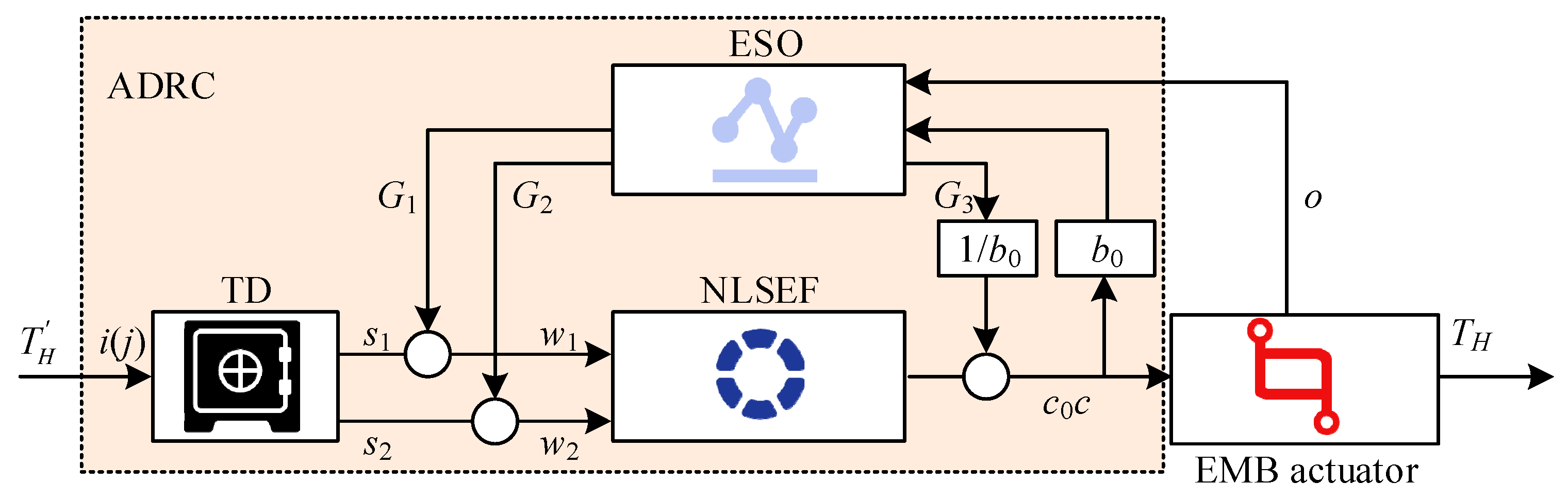
2.2. Optimization Method for ADRC Clamping Force Control Introducing PSO Algorithm

The nonlinear and time-varying characteristics of EMB systems make it difficult for traditional control methods to achieve precise control, especially in situations where high real-time and stability requirements are needed. ADRC can estimate and compensate for internal and external disturbances in real-time, improving the robustness and response velocity. Due to the interference and multiple uncertain factors of EMB actuators, the system is complex and difficult to accurately describe. Therefore, this study approximates the EMB actuator as a second-order nonlinear system, and the state equation of this system is shown in Equation (5).
s ˙ 1 = s 2 s ˙ 2 = f s 1 , s 2 + z · c t + r t o = s 1
In Equation (5), s 1 and s 2 are the state variables. z is the gain coefficient. c t is the control quantity. f s 1 , s 2 is a nonlinear function. r t is the system disturbance. o is the output of the system. ADRC has fast response time and high tracking accuracy. Applying it to EMB systems can solve the problems of time-delay response and precise control of actuators [19]. The ADRC structure diagram is shown in Figure 3.
In Figure 3, the ADRC controller includes three components: a Tracking Differentiator (TD), Nonlinear State Error Feedback (NLSEF), and ESO. Target signal i j is input, resulting in state variables s 1 and s 2 . The specific meanings of the two refer to the tracking value of i j and its differential estimation value. The system output o is the actual clamping force. c 0 and c are the system control variables before and after disturbance compensation. c represents the actual driving current. TD can address extracting continuous and differential signals from measurement signals that are discontinuous or contain random noise. Based on the differential output and the fastest synthesis function F h a n , the transition process of the closed-loop system can be arranged [20]. The form of TD discrete relationship is shown in Equation (6).
F h a n = F h a n s 1 j i j , s 2 j , v 0 , l 0 s 1 j + 1 = s 1 j + B · s 2 j s 2 j + 1 = s 2 j + b · f 1 , D = v 0 · l 0 D 0 = l 0 · D a 0 = D 2 + 8 v · o o = s 1 + l 0 · s 2
In Equation (6), v 0 and l 0 are the velocity factor and filtering factor, respectively. B is the integration step size. D and a are both nonlinear factors. NLSEF performs control and disturbance compensation based on the errors w 1 and w 2 between the given signal and its derivative obtained from TD, and the system output and its derivative observed by the state observer. The nonlinear control method is established by the nonlinear function f a l or the F h a n , and the relevant calculations are shown in Equation (7) [21].
w 1 = s 1 G 1 w 2 = s 2 G 2 c 0 = λ 1 · f a l w 1 , a 1 , n 1 + λ 2 · f a l w 2 , a 2 , n 2
In Equation (7), G 1 is the estimated value of o . The estimated differential value is G 2 . λ 1 and λ 2 are proportional coefficients and differential coefficients. n 1 and n 2 determine the size of the linear interval of the nonlinear function, with the value of n 0 . The calculation of the compensation control rate for the estimated Total Disturbance (TDis) G 3 is shown in Equation (8).
c t = c 0 G 3 / b 0
ESO expands the disturbance effect that affects the output of the controlled object into new state variables, and observes the expanded TDis signal through a special feedback mechanism input. The output construction TDis G 3 is a state variable. The second-order system has an extended observer that reaches the third-order and incorporates the state of TDis. The TDis includes internal disturbances and external high-frequency noise interference, and the relevant calculations are shown in Equation (9) [22].
G 1 j + 1 = G 1 j + B G 2 j p 1 q 1 G 2 j + 1 = G 2 j + B G 3 j p 2 · f a l q 1 , θ 1 , n 1 + b 0 · c G 3 j + 1 = G 3 j B p 3 · f a l q 1 , θ 2 , n 2 q 1 = G 1 j o
In Equation (9), p 1 , p 2 , and p 3 are all control parameters. q 1 is the error signal. b 0 is the correction factor. θ is the control parameter of the nonlinear function, 0 < θ < 1 . Due to the time-consuming and unsatisfactory results of conventional methods for determining parameters, to improve efficiency, this study separately optimizes the parameters of the three components of the ADRC controller. The PSO is suitable for nonlinear and multi-objective optimization problems and can be used to optimize the parameters of ADRC controllers. This study introduces PSO to improve optimization efficiency. The process of PSO participating in optimizing ADRC controller is shown in Figure 4.
In Figure 4, the first step is to initialize the PSO. Before this process, it is necessary to assign a value to the ADRC controller and run it. In the optimization process, it is necessary to evaluate the fitness function of each particle to determine whether its position is close to the optimal solution. PSO searches the solution space by continuously updating the position and velocity of particles, gradually approaching the global optimal solution. The relevant formulas for updating the particle velocity V j and particle position of the next iteration j + 1 are shown in Equation (10).
V j + 1 = ξ 1 V j + x 1 r a n d 1 e j m j + x 2 r a n d 2 e b e s t j m j m j + 1 = m j + V j
In Equation (10), m j is the particle of iteration j . e b e s t j is the optimal position obtained using j iterations. e j is the latest location. x 1 and x 2 are learning factors. To find a suitable balance between the global and local search for particles, x 1 and x 2 are both set to 2.0. To avoid significant differences between the two, which may prevent the algorithm from effectively exploring the solution space, the inertia weight ξ 1 is set to 0.5. This is conducive to exploring the solution space extensively in the early stage of optimization and refining the search in the later stage. r a n d 1 and r a n d 2 are both random numbers, with 0 < r a n d 1 1 and 0 < r a n d 2 1 . The initial parameters can be theoretically derived and empirically set, and parameter tuning can be combined with repeated experiments and PSO. The fitness function of PSO is based on the Integral of Time multiplied by the Absolute Error (ITAE). Optimization objective σ is the clamping force error and response time, calculated using Equation (11).
σ = 0 ε ε T H T H d ε
In Equation (11), T H T H is the clamping force error value and ε is the response coefficient. After the velocity and position of the particles are updated, the system will determine whether the optimization conditions are met. If the conditions are met, the optimal result will be output.

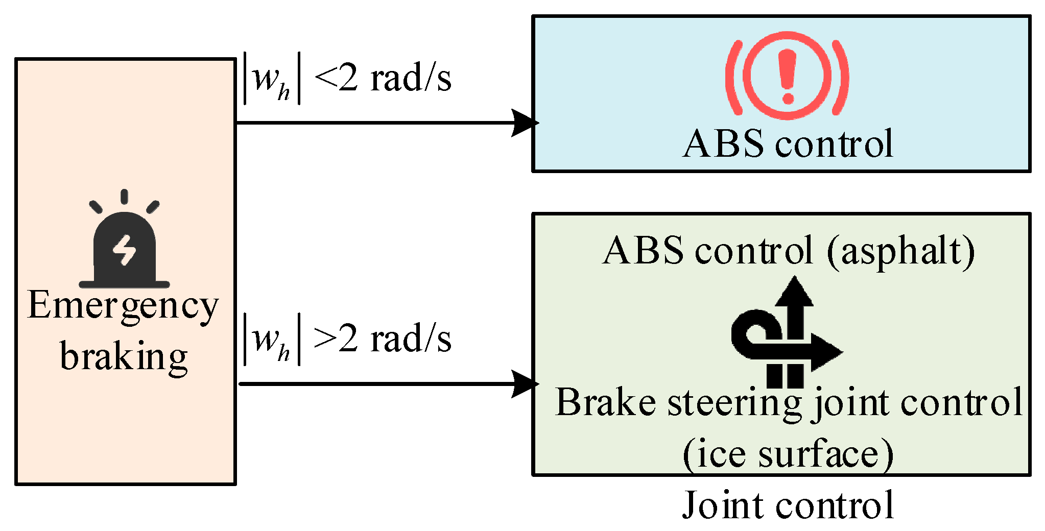
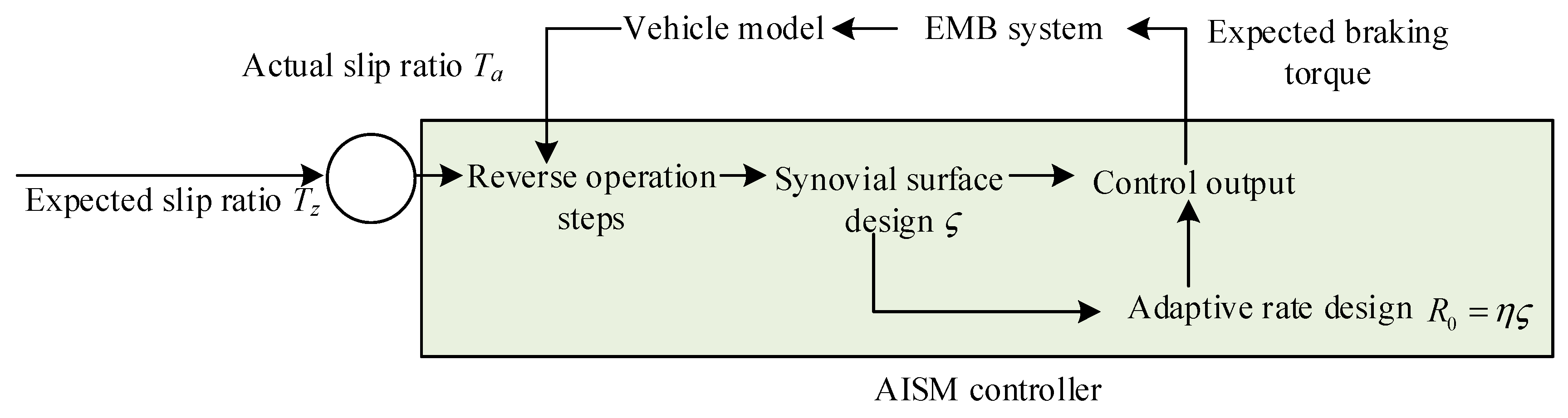
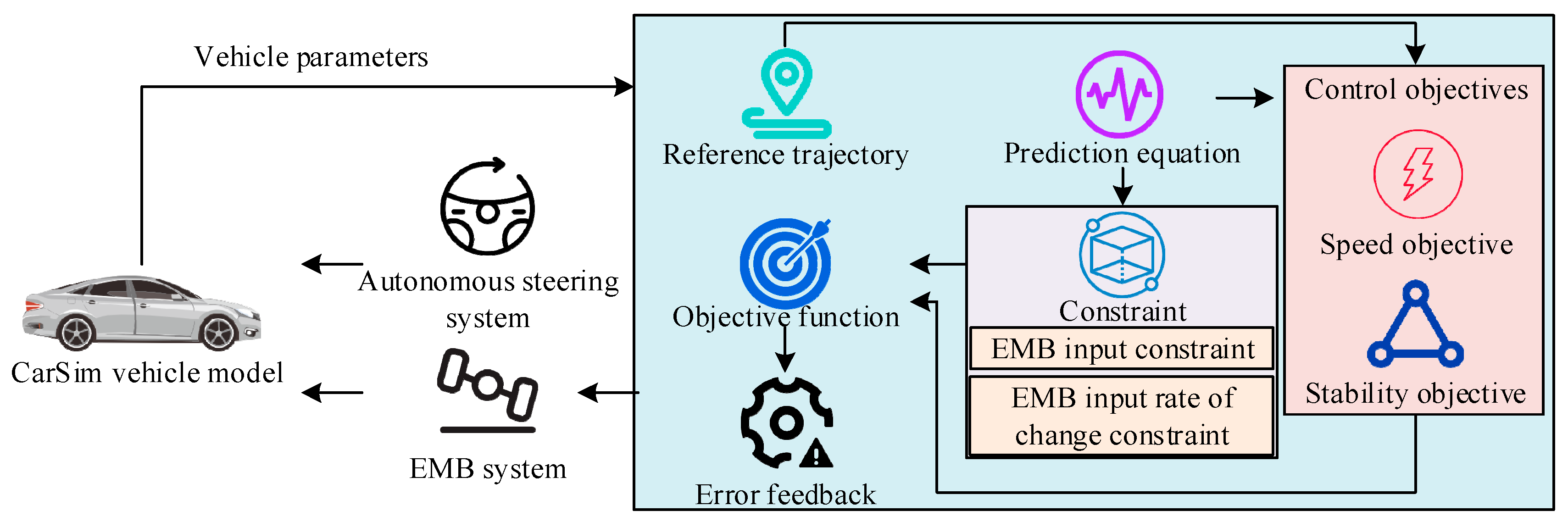
2.3. Joint Control Method for Steering and Braking

During emergency braking, relying solely on the ABS system may not fully guarantee the stability of the vehicle under complex road conditions. By incorporating an autonomous steering system, stability can be further enhanced by adjusting the steering angle of the vehicle’s front wheels. To achieve more comprehensive vehicle dynamic control, this study combined the EMB system, ABS, and autonomous steering system. The EMB system can be seamlessly integrated with ABS, providing more comprehensive vehicle dynamic control [23]. Considering the emergency braking of vehicles in actual road conditions and the special time lag of EMB systems, a joint controller was developed. The dynamic response of vehicles varies under various road adhesion conditions. The joint control method can adjust the control strategy based on actual road conditions to ensure braking effectiveness and vehicle stability under various conditions. The joint control structure in the VSS platform is shown in Figure 5.
In Figure 5, when w h < 2 rad/s, the vehicle tires are mainly controlled using ABS. At w h > 2 rad/s, control strategies are selected based on different road adhesion conditions. For low-grip road surfaces such as snow and ice, the side tires are controlled using ABS. For high-grip road surfaces, the side tires and front wheels are controlled using a combined steering and braking control system. By utilizing the fast response characteristics of the EMB system, combined with the stable control of ABS and the flexible adjustment of the autonomous steering system, more efficient braking control was achieved. The derivative of T z is T ˙ z , and the derivative κ ˙ equation of the wheel slip ratio κ is shown in Equation (12) [24].
κ ˙ = 1 b 1 κ z + E 2 H G X λ κ + E H b T z T ˙ z = 1 ς b + f 1 T z + 1 ς b + f 1 u 1
In Equation (12), ς b is the average time for EMB actuators to respond to control signals under normal operating conditions. f is the change in actuator response time caused by external disturbances or complex physical processes in the system. E is the system prediction equation. EMB actuators have response lag, which common ABS control methods cannot effectively handle, thereby affecting control accuracy and response speed. Meanwhile, the ABS system needs to maintain the desired slip ratio to ensure effective deceleration and stability of the vehicle during braking. However, traditional ABS systems have shortcomings when facing time delay, uncertainty, and complex dynamic environments. To address these issues, Adaptive Inverse Sliding Mode (AISM) control was introduced into the ABS system to optimize its performance. AISM control is an advanced control method that fuses adaptive control and sliding mode control. The adaptability enables this control method to adjust control parameters in real-time according to environmental changes. Reverse sliding mode improves the robustness of the system to uncertainties and disturbances. AISM can self-adjust control parameters built on dynamic characteristics, enabling the control system to maintain high efficiency and stability even in the face of different road conditions and dynamic environments. The control framework for optimizing the ABS system is shown in Figure 6.
In Figure 6, the system first receives the expected slip ratio to ensure that the vehicle can effectively decelerate without losing stability during braking. The controller performs reverse operation steps to calculate the required control inputs to achieve the desired slip ratio. Then, sliding mode surface ς is designed to determine the system state deviation, and the control input is adjusted through sliding mode control law to make the system state approach the ς . The adaptive rate is R 0 , and η is a normal number, which enables the controller to self-adjust according to the dynamic characteristics, thereby improving control accuracy and robustness. The controller calculates the expected braking torque and inputs it into the EMB system. The EMB system receives the expected braking torque T z and outputs the actual braking torque T a . The EMB system has fast response capability and can accurately apply braking torque. The actual braking torque is applied to the vehicle model. The vehicle model outputs the actual slip rate. The actual slip rate is compared with the expected slip rate, the difference is fed back to the AISM controller, and the reverse sliding film control law is adjusted to further optimize the braking effect [25]. The inverse synovial control law is the core part of this control framework. The expression for the actual control input i a is shown in Equation (13).
i a = ς b 1 ς b c 4 v 0 H x 4 v 1 x 3 + s ˙ 1 G ¯ sgn ς k 1 ς ϕ sgn ς
In Equation (13), both k 1 and ϕ are normal numbers. x 3 and x 4 are the actual control quantity and the expected control quantity. G ¯ sgn ς is the aggregated uncertainty caused by time delay. By selecting appropriate weights, it can be ensured that the control system is asymptotically stable under Lyapunov stability theory, that is, the system state can gradually approach the expected state [26]. The expression for the weight diagonal matrix W is shown in Equation (14).
W = v 1 k 1 v 0 2 H 2 k 1 v 0 H 2 k 1 v 0 k 1
In Equation (14), appropriate k 1 , c 0 , and c 1 values are selected to ensure that the matrix always has positive values. For high adhesion road surfaces, model predictive control method is used for joint control, setting control objectives for vehicle stability and speed, and considering constraints on EMB input and its rate of change. The framework of the joint control model is displayed in Figure 7.
In Figure 7, the vehicle model sets control objectives for stability and speed, as well as constraints on EMB input and its rate of change, based on the prediction equation and reference trajectory under the influence of vehicle parameters. The objective function is obtained under control objectives and constraints, and error feedback is performed [27]. After feedback to the autonomous steering system and EMB system, the parameters obtained by both are output to the model. To simplify the controller design, this study set the time delay of EMB braking and steering braking as fixed values. The joint control system dynamically adjusts the braking and steering control strategies built on the current road conditions, vehicle status, and target requirements to achieve more efficient braking effects [28,29]. The cost function K at time k + 1 measures the quality of joint control, as given in Equation (15).
K = Z × E k + 1 k R 1 k + 1 2
In Equation (15), Z is the importance of different parameters. R 1 is a first-order exponential function reference vector. This study proposes a joint control method for complex operating conditions by jointly optimizing EMB and ABS systems. This can optimize braking performance and enhance the robustness of the vehicle to external disturbances while ensuring vehicle stability, thereby improving the overall control performance of the VSS platform.

3. Results

This study first obtained the test results of EMB control on the testing platform, and then evaluated the optimized ABS control method in different scenarios. For the joint control method, this study selected different road surface types for practical application analysis.

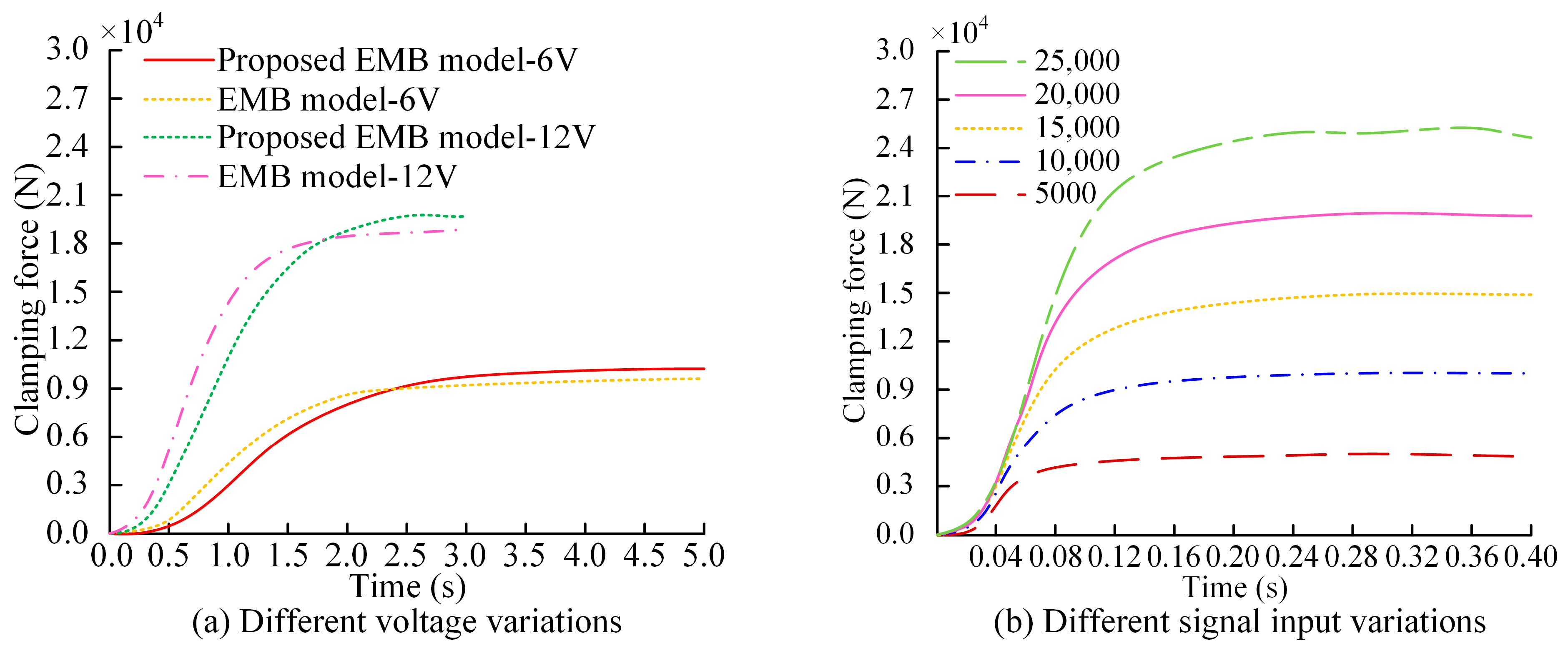
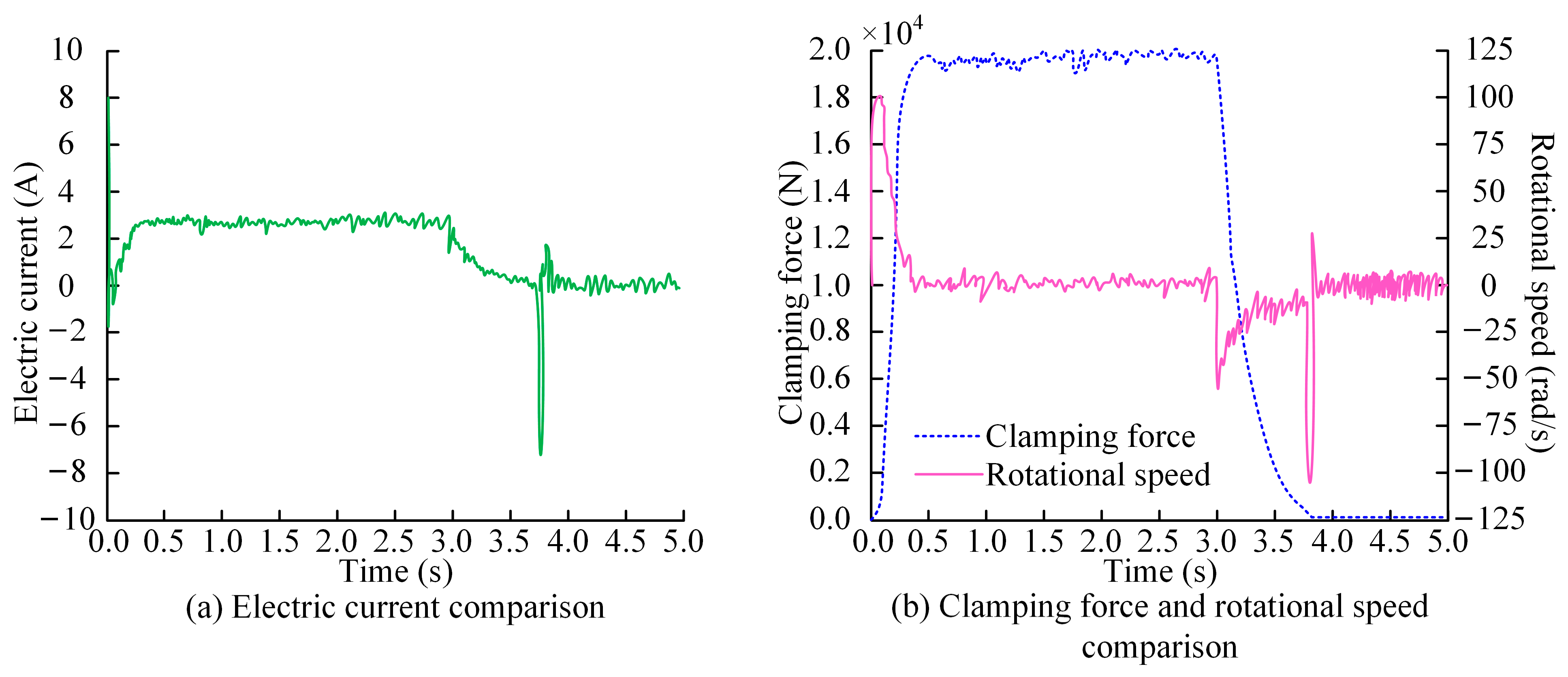
3.1. EMB Control Test Results

This study selected a semi-physical hardware in the loop-testing platform on a Windows 10 operating system with 32 GB memory. The hardware configuration included an EMB prototype, Hardware Control Unit (HCU) upper computer, HCU, and real-time simulator. The software configuration requires NI VeriStand v24.5.0 testing software and Matlab/Simulink 9.1 models [30]. The semi-physical hardware in the loop-testing platform can greatly improve the debugging efficiency and avoid conducting high-risk experiments directly on real hardware. We assumed that it was not affected by sensor errors and provided sufficient real-time feedback. After PSO optimization parameters, Table 1 shows the parameter settings for ADRC.
To verify the performance of the developed EMB actuator in practical applications, this study evaluated its performance under real conditions. To this end, it compared the changes in current, speed, and clamping force between the developed EMB actuator and actual signals. The changes in current, speed, and clamping force of the actual signal and the developed EMB actuator at the same time are shown in Figure 8.
In Figure 8a, within 5.0 s, the current changes in the developed EMB actuator are basically consistent with the actual signal. The developed EMB actuator can track actual signals well in terms of current changes, with a high response speed and control accuracy. The current change curve first rises and then remains unchanged, finally stabilizing at 2.45 A. After reaching the preset state, the system can maintain a stable current output, and its current response characteristics meet the design requirements. In Figure 8b, the current variation of the developed EMB actuator is basically consistent with the actual signal. The rotational speed underwent a gradual decline from 26 rad/s to 0, reaching a complete halt at 1.9 s. This outcome signifies the system’s commendable fast response capability. During emergency braking of the vehicle, other components, such as the ABS and Electronic Stability Control of the braking system, usually need to cooperate and react, and a complete stop in speed within 1.9 s can provide enough time to distribute power. The two are highly consistent in terms of speed variation, indicating good dynamic response and deceleration performance. In Figure 8c, the clamping force variation trend between the developed EMB actuator and the actual signal first increases and then remains stable. The actual signal and the clamping force of the developed EMB actuator ultimately stabilize at 2.11 × 10⁴ N and 2.16 × 10⁴ N. Although there is a slight difference in the final clamping force value, the overall trend of change is very close to the final stable value, indicating that the developed EMB actuator can track the actual signal well. The EMB actuator developed has high accuracy and reliability in clamping force control.
To verify the consistency between the EMB model and the actual model in terms of clamping force response characteristics, the same 6 V and 12 V voltages were sent to both models, and the changes in clamping force over time were recorded. Meanwhile, the control performance of ADRC on clamping force was compared under different clamping forces. The clamping force variation curve obtained is shown in Figure 9.
In Figure 9a, there is a certain gap between the proposed model and the actual physical model at 6 V and 12 V. However, the clamping force response characteristics of the two have a good similarity. The research model can better reflect the dynamic behavior of the actual system and meet the requirements of system development. In Figure 9b, the ADRC controller is able to quickly and stably track the target clamping force in the clamping force range of 5000 N to 25,000 N during testing. It showed a strong adaptability to different expected clamping forces. The ADRC controller can achieve a fast and stable tracking response under different clamping force conditions, effectively dealing with disturbances and uncertainties in the system.
To verify the influence of the EMB on various parameters at different stages, it is expected that the clamping force will be set as a two-stage step change. The first paragraph shows a step change in clamping force to 20 kN at 0 s. The second paragraph states that at 3.0 s, the clamping force will step back to 0. During the simulation of rapid changes in the brake clamping force, the EMB motor speed, clamping force, and current response are shown in Figure 10.
In Figure 10a, the current drops rapidly at 0 s, then gradually increases within 0.2 s, and finally stabilizes at 2.4 A at 3.0 s. The optimization control method ensures that the system no longer responds significantly to external disturbances, such as current changes and load disturbances. Consequently, this improves the system’s anti-interference ability. The current slowly decreases from 3.0 s to 5.0 s because the system’s current can stabilize to the target value in a short period. During the process of clamping force variation, the current fluctuation is relatively small. The system can quickly recover and maintain stable operation under external disturbances, such as load changes and environmental disturbances, reducing sensitivity to external disturbances. In Figure 10b, the clamping force rapidly increases from 0 N to 20 kN within approximately 0.5 s. The system can quickly respond to input and achieve the target clamping force. After holding for 3.0 s, the clamping force begins to decrease to 0.0001 N. The speed increases from 0 to 100 rad/s within 0.5 s. The brake quickly increases to the target speed at the beginning, then enters a stable working state, and then rapidly decreases to 0. The speed remains at 0 during the period of 0.5 s~3.0 s, negative during the period of 3.0 s~3.8 s, and the maximum speed exceeds −100 rad/s. The system design takes into account the need for reverse braking or releasing braking.

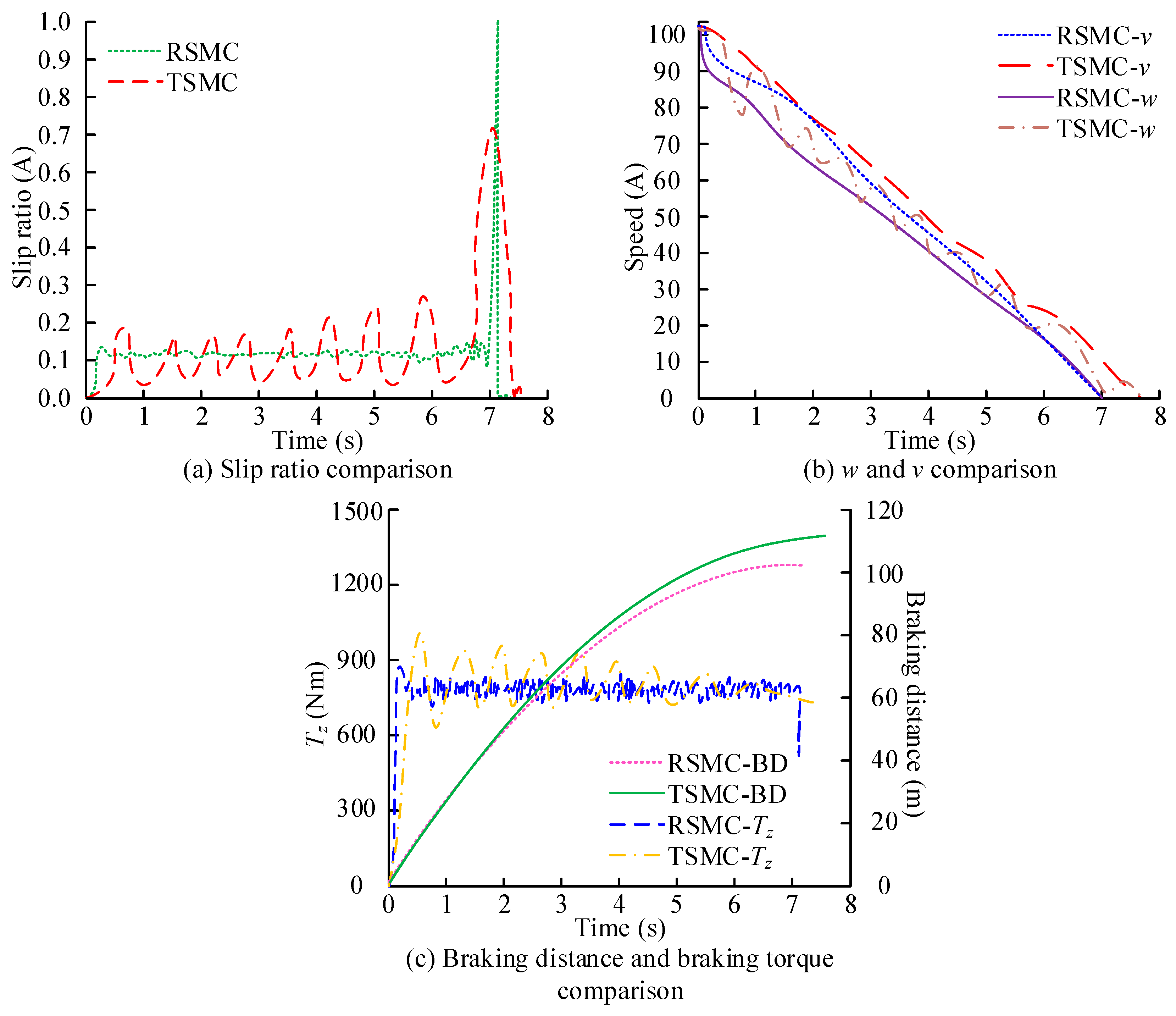
3.2. Analysis of ABS Control Effect

To evaluate the performance of optimization control methods in improving ABS systems, experiments were conducted on two types of road surfaces: asphalt pavement and ice and snow pavement. We assumed that the two types of road surfaces represent good and poor friction conditions, respectively, while the friction coefficient of each road surface remained unchanged. At the same time, we did not take into account the frequent transition of vehicles from dry asphalt to icy and snowy roads. The effects of the optimized and the original control methods were compared under different road conditions, as listed in Table 2.
In Table 2, the Root Mean Square Error (RMSE) of the slip ratio of the optimized control method is 0.0498 and 0.0149 on asphalt and icy roads. Compared to the original control method, the optimization method can achieve a more accurate slip ratio control. The maximum slip rate error of the optimization method was 0.0428 and 0.0632, which reduced the maximum error by about 12.9% compared to the original method. On asphalt pavement, the current RMSE of the optimization method was 2.3522, while that of the original method was 3.6477. The optimization method reduces current fluctuations, making it more stable and efficient in the control process.
The experiment selects typical asphalt pavement to represent the situation of normal dry pavement. The test vehicle was equipped with an ABS system and a Traditional Sliding Mode Controller (TSMC) and an optimized Reverse Sliding Mode Controller (RSMC). TSMC has found widespread application in various automatic control systems, and its implementation is relatively straightforward, obviating the necessity for complex optimization or adaptation mechanisms. The TSMC has demonstrated the capacity to expeditiously respond and adapt to dynamically changing system states, exhibiting the ability to swiftly adjust control inputs in the face of drastic changes in the system state. The optimized control was compared with the original strategy, as shown in Figure 11.
In Figure 11a, the RMSE of the RSMC is 0.06, which is 8.6% lower than the TSMC. The RSMC can more accurately control the wheel slip ratio near the target value, reduce slip ratio jitter, and improve the stability of the braking system. In Figure 11b, the RSMC causes a faster decrease in wheel speed v and angular velocity w , while the fluctuation of wheel angular velocity is smaller. The RSMC can respond to braking demands more quickly, while reducing unnecessary fluctuations during the braking process and improving the smoothness of the braking process. In Figure 11c, compared to the TSMC, the optimized RSMC can reach maximum T z faster. Meanwhile, the optimized braking distance (BD) is relatively small, ultimately reaching approximately 43 m at 3.0 s. The TSMC cannot automatically adjust control strategies based on different road conditions or environmental changes, resulting in sub-optimal braking performance on icy roads.
To further validate the effectiveness of the RSMC, this study conducted tests on local icy roads. An icy road surface represents a slippery road surface with a low coefficient of friction. The comparison under different control methods is shown in Figure 12.
In Figure 12a, on icy and snowy roads, the RSMC has better control performance than the TSMC, with a 9.2% reduction in the RMSE. This controller performs more stably on low-friction road surfaces and can better control the slip ratio of the wheels, thereby ensuring safer braking of the vehicle on such road surfaces. In Figure 12b, the RSMC intervenes earlier, resulting in a faster decrease in the wheel angular velocity and reduced fluctuations in the wheel speed. The effectiveness of this controller on slippery roads, such as those with ice and snow, can better maintain the stability of the wheels, thereby improving the smoothness and response speed of braking. In Figure 12c, the BD on icy and snowy roads is reduced by 8 m, and the RSMC can effectively improve the braking strength and reduce the braking distance. This is crucial for improving braking safety. On slippery roads, vehicles are more likely to lose control or experience longer braking distances. The controller can not only quickly respond to braking demands, but also reduce overshoot and fluctuations, further improving the braking stability and driving safety of the vehicle.
This study compared road conditions with different friction coefficients and analyzed the control effect of joint control methods on vehicle dynamic behavior under various driving conditions. The initial vehicle speed was set to 102 km/h to simulate emergency braking scenarios. The vehicle adopted a designed joint controller to adjust the distribution of four-wheel braking force. The friction coefficient on the left side was 0.2, compared to the road surfaces with friction coefficients of 0.4 and 0.6 on the right side. Table 3 shows the effectiveness of the joint control method.
In Table 3, on a road surface with a friction coefficient of 0.4, the maximum lateral braking deviation of the joint controller is 0.148 m, while the optimal slip ratio control value for low adhesion roads is even higher at 0.243 m. The joint controller could better reduce the lateral deviation, improve the stability of the vehicle, and performed well under low-friction conditions. The longitudinal braking distance under this control is 153.4 m, while the optimal slip ratio control method for low-adhesion road surfaces is a longer 113.2 m. At lower friction coefficients, the joint controller provides a more efficient braking performance. The joint controller effectively reduces the lateral displacement of the vehicle, making it more stable during braking. Meanwhile, this control method can effectively reduce the vehicle’s yaw angle and maintain a good driving trajectory.

4. Conclusions

This study first established an EMB system and introduced a PSO of ADRC control parameters to improve the system control accuracy. Meanwhile, the ABS system was combined to jointly control the braking and steering control of vehicles on multiple types of road surfaces. The results indicated that compared to the original control method, the optimized control method could achieve more accurate slip ratio control. The maximum slip rate errors of the optimization method were 0.0428 and 0.0632. Compared to the original method, it reduced the maximum error by approximately 12.9%. On an asphalt pavement, the current RMSE of the optimization method was 2.3522, while with the original method it was 3.6477. The optimization method reduced current fluctuations, making it more stable and efficient in the control process. The optimization method outperformed the original method under all testing conditions. The optimization method has shown significant advantages in terms of slip rate control accuracy, current consumption stability, and reduction of maximum slip rate error. In the low-friction environment of ice and snow roads, the advantages of optimization methods were more obvious, which could provide more stable and safe braking performance and reduce system energy consumption. Therefore, the application of optimization methods in ABS systems will significantly improve the braking effect and driving safety of vehicles under various road conditions. Compared with a TSMC, this controller has higher control accuracy and response speed under different road conditions. It can effectively improve the braking performance and safety, reduce unnecessary fluctuations and wear during the braking process, and has important engineering application value. However, the study did not take into account the changes in braking effectiveness under the influence of driving behavior and environmental factors. Factors such as the driver’s operating method and the force applied to the brakes can all affect the dynamic behavior of the vehicle. In the future, the development of an intelligent detection instrument that can predict changes in driver behavior may enhance the stability and safety of the system in a variety of driving scenarios.

Author Contributions

Methodology, X.S.; Validation, X.S.; Writing—original draft, F.Y.; Writing—review & editing, X.R. All authors have read and agreed to the published version of the manuscript.

Funding

This research received no external funding.

Data Availability Statement

Data are contained within the article.

Conflicts of Interest

Author Fei Yang was employed by the company Chongqing Changan Wangjiang Industrial Group Co., Ltd. Author Xiaopeng Su was employed by the company Chongqing Changan Wangjiang Industrial Group Co., Ltd. The remaining authors declare that the research was conducted in the absence of any commercial or financial relationships that could be construed as a potential conflict of interest.

References

  1. Shaojun, L.; Yingjie, L.; Wei, L.; Zhe, X.; Guoyou, W.; Yan, X.; Fansheng, J. Resonance Suppression Method of Vehicle Mounted Lifting Photoelectric Platform. Infrared Technol. 2024, 46, 406–412. [Google Scholar]
  2. Duan, S.C.; Sun, J.; ‘Frank’Bai, X.X.; Nguyen, Q.H.; Si, Z.Y.; Li, W.H.; Liu, Y. Principle design and control of a brake-by-wire actuator featuring magnetorheological clutch. Proc. Inst. Mech. Eng. Part D J. Automob. Eng. 2023, 237, 793–802. [Google Scholar] [CrossRef]
  3. Chen, G.; Zhao, X.; Gao, Z.; Hua, M. Dynamic drifting control for general path tracking of autonomous vehicles. IEEE Trans. Intell. Veh. 2023, 8, 2527–2537. [Google Scholar] [CrossRef]
  4. Nguyen, T.A.; Iqbal, J. Improving stability and adaptability of automotive electric steering systems based on a novel optimal integrated algorithm. Eng. Comput. 2024, 41, 991–1034. [Google Scholar] [CrossRef]
  5. Gao, B.; Zheng, L.; Shen, W.; Zhang, W. A summary of parameter tuning of active disturbance rejection controller. Recent Adv. Electr. Electron. Eng. (Former. Recent Pat. Electr. Electron. Eng.) 2023, 16, 180–196. [Google Scholar] [CrossRef]
  6. Wng, Y.; Hu, Z.; Li, Y.; Zhang, X.; Cui, Y. Current Predictive Control of Electro-Mechanical Braking System for Unmanned Tracked Vehicles. Trans. Beijing Inst. Technol. 2024, 44, 792–800. [Google Scholar]
  7. Song, B.K.; Kim, J.H.; Hwang, K.Y.; Lim, M.S. Electro-mechanical characteristics of dual-winding motor according to winding arrangement for brake systems in highly automated driving vehicles. IEEE Trans. Veh. Technol. 2023, 72, 12524–12539. [Google Scholar] [CrossRef]
  8. Zhou, S.; Liu, J.; Wng, Z.; Sun, S. Research on Design Optimization and Simulation of Regenerative Braking Control Strategy for Pure Electric Vehicle Based on EMB Systems. Trans. FAMENA 2023, 47, 33–49. [Google Scholar] [CrossRef]
  9. Xu, Z.; Gerada, C. Enhanced estimation of clamping-force for automotive EMB actuators using a switching extended state observer. IEEE Trans. Ind. Electron. 2023, 71, 2220–2230. [Google Scholar] [CrossRef]
  10. Zhao, Y.; Lin, H.; Elahi, H.; Miao, F.; Riaz, S. Clamping force sensor fault analysis and fault-tolerant control of the electromechanical brake system. Arab. J. Sci. Eng. 2023, 48, 6011–6023. [Google Scholar] [CrossRef]
  11. Wng, J.; Wang, X.; Luo, Z.; Assadian, F. Active Disturbance Rejection Control of Differential Drive Assist Steering for Electric Vehicles. Energies 2020, 13, 2647. [Google Scholar] [CrossRef]
  12. Zhao, L.; Wng, N.; Xia, G.; Mei, X.; Wng, H.; Zhang, D. Regenerative braking torque compensation control based on improved ADRC. Proc. Inst. Mech. Eng. Part D J. Automob. Eng. 2024, 238, 1315–1329. [Google Scholar] [CrossRef]
  13. Jin, H.; Gao, Z. On the notions of normality, locality, and operational stability in ADRC. Control Theory Technol. 2023, 21, 97–109. [Google Scholar] [CrossRef]
  14. Liu, L.; Liu, Y.; Zhou, L.; Wng, B.; Cheng, Z.; Fan, H. Cascade ADRC with neural network-based ESO for hypersonic vehicle. J. Frankl. Inst. 2023, 360, 9115–9138. [Google Scholar] [CrossRef]
  15. Safiullah, S.; Rahman, A.; Lone, S.A. A second-order ADRC for synchronized frequency-voltage mitigation of EV integrated power system. IETE J. Res. 2024, 70, 515–530. [Google Scholar] [CrossRef]
  16. Madonski, R.; Herbst, G.; Stankovic, M. ADRC in output and error form: Connection, equivalence, performance. Control Theory Technol. 2023, 21, 56–71. [Google Scholar] [CrossRef]
  17. Zhao, Y.; Lin, H.; Miao, F. An adaptive backstepping nonsingular fast terminal sliding-mode control for the electromechanical brake system with backlash nonlinearity compensation. Proc. Inst. Mech. Eng. Part F J. Rail Rapid Transit 2023, 237, 858–870. [Google Scholar] [CrossRef]
  18. Chen, Q.; Lv, Z.; Tong, H.; Zeng, D.; Ouyang, L.; Liu, Q. Study on multi-closed loop control of electro-mechanical braking for electric vehicles based on clamping force. Proc. Inst. Mech. Eng. Part D J. Automob. Eng. 2024, 238, 4245–4254. [Google Scholar] [CrossRef]
  19. Anderson, E.; Fan, F.R.; Cai, J.; Holtzmann, W.; Taniguchi, T.; Watanabe, K.; Xiao, D.; Yao, W.; Xu, X. Programming correlated magnetic states with gate-controlled moire geometry. Science 2023, 381, 325–330. [Google Scholar] [CrossRef]
  20. Shen, Q.; Huang, S.; Sun, B.; Chen, X.; Tao, D.; Wan, H.; Bao, E. PVII: A pedestrian-vehicle interactive and iterative prediction framework for pedestrian’s trajectory. Appl. Intell. 2024, 54, 9881–9891. [Google Scholar] [CrossRef]
  21. Son, S.J.; Meetei, T.S.; Park, D.K. Wide Optical Beam Steering LCOS Device for Solid-State LiDAR Applications. IEEE Photonics Technol. Lett. 2024, 36, 35–38. [Google Scholar] [CrossRef]
  22. Lee, D.H. Efficient perception, planning, and control algorithm for vision-based automated vehicles. Appl. Intell. 2024, 54, 8278–8295. [Google Scholar] [CrossRef]
  23. Lancaster, P.; Mavrogiannis, C.; Srinivasa, S.; Smith, J.R. Electrostatic brakes enable individual joint control of underactuated, highly articulated robots. Int. J. Robot. Res. 2024, 43, 2204–2220. [Google Scholar] [CrossRef]
  24. Zhu, S.; Fan, X.; Qi, G.; Wng, P. Review of control algorithms of vehicle anti-lock braking system. Recent Pat. Eng. 2023, 17, 30–45. [Google Scholar] [CrossRef]
  25. Kong, X.; Deng, Z.; Zhao, Y.; Gao, W. Stability control of distributed drive electric vehicle based on adaptive fuzzy sliding mode. Proc. Inst. Mech. Eng. Part D J. Automob. Eng. 2024, 238, 2741–2752. [Google Scholar] [CrossRef]
  26. Yin, C.; Mei, Z.; Feng, Y.; Tang, L. A novel traction control strategy for an electric bus. Int. J. Veh. Perform. 2024, 10, 215–237. [Google Scholar] [CrossRef]
  27. Yang, T.; Li, P.; Li, Q.; Li, Z. Vehicle stability control strategy for high-speed curves based on mode switching. Proc. Inst. Mech. Eng. Part D J. Automob. Eng. 2024, 238, 3825–3842. [Google Scholar] [CrossRef]
  28. Gao, L.; Gao, Q.H.; Cheng, H.J.; Liu, Z.; He, X. Multi-body modeling and dynamic analysis of the heavy-load multi-axle vehicle Based on 6S/6M ABS control. Proc. Inst. Mech. Eng. Part D J. Automob. Eng. 2024, 238, 491–508. [Google Scholar] [CrossRef]
  29. Zeng, X.; Gao, H.; Song, D.; Li, L. Coordinated control algorithm of lateral stability of hybrid electric commercial vehicle. Proc. Inst. Mech. Eng. Part D J. Automob. Eng. 2024, 238, 2767–2785. [Google Scholar] [CrossRef]
  30. Nagarkar, M.; Bhalerao, Y.; Sashikumar, S.; Sashikumar, S.; Hase, V.; Navthar, R.; Zaware, R.; Surner, N. Multi-objective optimization and experimental investigation of quarter car suspension system. Int. J. Dyn. Control 2024, 12, 1222–1238. [Google Scholar] [CrossRef]
Figure 1. EMB system structure and working mechanism.
Electronics 14 00752 g001
Figure 2. Composition of EMB actuator model constructed.
Electronics 14 00752 g002
Figure 3. ADRC structure diagram.
Electronics 14 00752 g003
Figure 4. PSO algorithm participating in optimizing ADRC controller process.
Electronics 14 00752 g004
Figure 5. Joint control structure.
Electronics 14 00752 g005
Figure 6. Optimize the control framework of ABS system.
Electronics 14 00752 g006
Figure 7. Joint control model architecture.
Electronics 14 00752 g007
Figure 8. Performance comparison of EMB actuators.
Electronics 14 00752 g008
Figure 9. Clamping force comparison.
Electronics 14 00752 g009
Figure 10. Effect of the EMB multi-stage control approach.
Electronics 14 00752 g010
Figure 11. Asphalt pavement test results.
Electronics 14 00752 g011
Figure 12. Ice pavement test results.
Electronics 14 00752 g012
Table 1. ADRC parameter settings.
ParametersNumerical Value
Integral step size B 1.0 × 10⁻⁴
Speed factor v 0 2.0 × 10⁶
Correction factor b 0 7.4 × 10⁵
Scale factor λ 1 4.5 × 10⁻⁴
Differential coefficient λ 2 1.6 × 10⁻⁴
Control parameter p 1 1067
Control parameter p 2 101,525
Control parameter p 3 651.7 × 10⁶
Table 2. The effect of the two control methods for different pavement types.
Road Surface TypeAsphalt PavementIce Road SurfaceDocking with the Road Surface
Control MethodOptimized ControlOriginal ControlOptimized ControlOriginal ControlOptimized ControlOriginal Control
RMSE of slip ratio0.04980.05220.01490.01720.01730.00178
Maximum slip rate error0.04280.04920.06320.12660.02330.0947
RMSE of current2.35223.64771.41373.46861.61432.0705
Table 3. Effectiveness of joint control methods in different situations.
Road Surface Type0.40.6
Maximum lateral braking deviation (m)0.1480.243
Longitudinal braking distance (m)153.4113.2
Maximum center of mass lateral deviation angle (°)1.8024.193
Maximum lateral angular velocity (°/s)3.8804.343
Maximum yaw angle (°)2.3273.654
Disclaimer/Publisher’s Note: The statements, opinions and data contained in all publications are solely those of the individual author(s) and contributor(s) and not of MDPI and/or the editor(s). MDPI and/or the editor(s) disclaim responsibility for any injury to people or property resulting from any ideas, methods, instructions or products referred to in the content.

