Abstract
In this paper, a novel Colpitts voltage-controlled oscillator (VCO) with low phase noise and an octave frequency tuning range is presented. To achieve low phase noise and a wide tuning range concurrently, the designed VCO employs quad-core-coupled structures, series resonators, dual-mode-coupled inductors, and push–push structures. The quad-core-coupled structures are used for phase noise improvement. The presented series resonators effectively expand the tuning range while reducing phase noise deterioration from amplitude-to-phase modulation (AM/PM) conversion. The dual-mode operation based on coupled inductors and quad-core structures further expands the tuning range. In addition, the adopted push–push structure increases the output frequency. Designed in a 180 nm SiGe BiCMOS process, the proposed Colpitts VCO operates from 7.2 to 14.5 GHz with an octave tuning range of 67.3%. The phase noise ranges from −131.4 to −121.8 dBc/Hz with a peak figure-of-merit (FoM) of 183.0 dBc/Hz and figure-of-merit-tuning (FoMT) of 199.5 dBc/Hz at a 1 MHz offset. The proposed VCO exhibits superior performance in phase noise and tuning range and achieves an octave tuning range for the first time in Colpitts VCOs.
1. Introduction
With the rapid development of modern wireless communication systems, the requirements for high-performance clocks are becoming more stringent. Voltage-controlled oscillators (VCOs) are the key components within clock modules, and the phase noise of VCOs has a significant impact on the signal quality of the overall communication system. VCOs with low phase noise can substantially reduce signal distortion and noise interference, thereby improving the performance and stability of communication systems. At present, frequency spectrum resources are scarce, and high-speed, high-capacity communication systems are prevalent, which makes stronger demands on wide frequency tuning ranges of VCOs necessary [1,2]. In some broadband applications, VCOs are required to cover an octave tuning range, which enables a full-range frequency band for the system [1].
In some specific applications, such as synthetic aperture radars (SARs), automotive radars, precision measurement, testing equipment, and high-performance ADCs/DACs, there are extremely strong demands for VCOs with ultra-low phase noise and a wide frequency range, with less emphasis on low-power consumption and small chip areas. These requirements are crucial to ensure accuracy, high resolution, and robust interference resistance across various operational environments.
Among several typical types of on-chip VCOs, LC oscillators have better phase noise performance than ring oscillators and relaxation oscillators [3,4]. In order to scale down the phase noise, multi-core-coupled VCOs are proposed, which achieve a phase noise reduction of 10log10N compared to single VCOs [5,6,7,8,9,10,11,12,13,14]. Employing series resonance with a higher tank Q-factor can also achieve phase noise improvement, which has been validated in refs [14,15,16,17]. These mainstream methods are used to achieve ultra-low phase noise; however, the tuning ranges are limited due to the trade-off between phase noise and tuning gain [18,19,20,21,22].
In recent years, mode-switching technology based on multi-core VCOs has been widely used in the design of wideband LC oscillators [5,6,7,8,9,10]. By changing the phase relationship between the cores, two or more effective resonant inductor values in the tank can be realized. Combined with switched capacitor arrays, these VCOs cover a wideband frequency range, and the highest bandwidth has exceeded 100% [6]. However, with the increase in cores and modes, the phase noise performance of mode-switching VCOs could degrade due to the mismatch between cores and the loss of tank Q-factor.
Among LC oscillators, Colpitts VCOs have lower phase noise than cross-coupled VCOs, resulting from their excellent cyclostationary noise properties [23,24]. From the S-band to the K-band, Colpitts VCOs exhibit superior phase noise performance, which is suitable for ultra-low phase noise application [25,26,27,28,29,30,31,32]. However, due to the distribution characteristics of feedback capacitors and more parasitic capacitance, it is difficult for Colpitts VCOs to achieve a wide tuning range using mode-switching and switched capacitor banks. Several Colpitts VCOs are reported to expand the tuning range using different techniques. The tank consisting of four VCO cores operated from 18.2 to 29.3 GHz in ref. [26]; nevertheless, the tuning range of a single core is only about 18%. Multiple varactor units were employed in [27], which realized a 30% tuning range. Tuning ranges of about 20% can be achieved using large, switched capacitor banks [28,31], which may degrade phase noise and negative resistance characteristics. The tuning ranges of these Colpitts VCOs are all less than 35%.
To expand the tuning range of Colpitts VCOs while maintaining low phase noise, a Colpitts VCO with quad-core-coupled structures and series resonators is proposed, as shown in Figure 1. The quad-core structure consists of four coupled Colpitts VCO cores, which improve phase noise performance. The presented series resonator expands the tuning range and reduces the degradation of phase noise. The dual-mode operation is employed based on quad-core structure and coupled inductors, which realize an octave tuning range. The adopted push–push structure increases the output frequency. Based on these techniques, the proposed VCO operates from 7.2 to 14.5 GHz and achieves a tuning range of 67.3% with phase noise from −131.4 to −121.8 dBc/Hz at a 1 MHz offset.
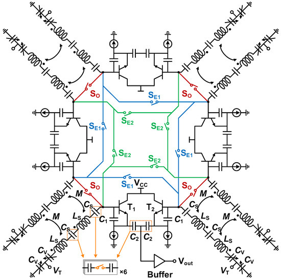
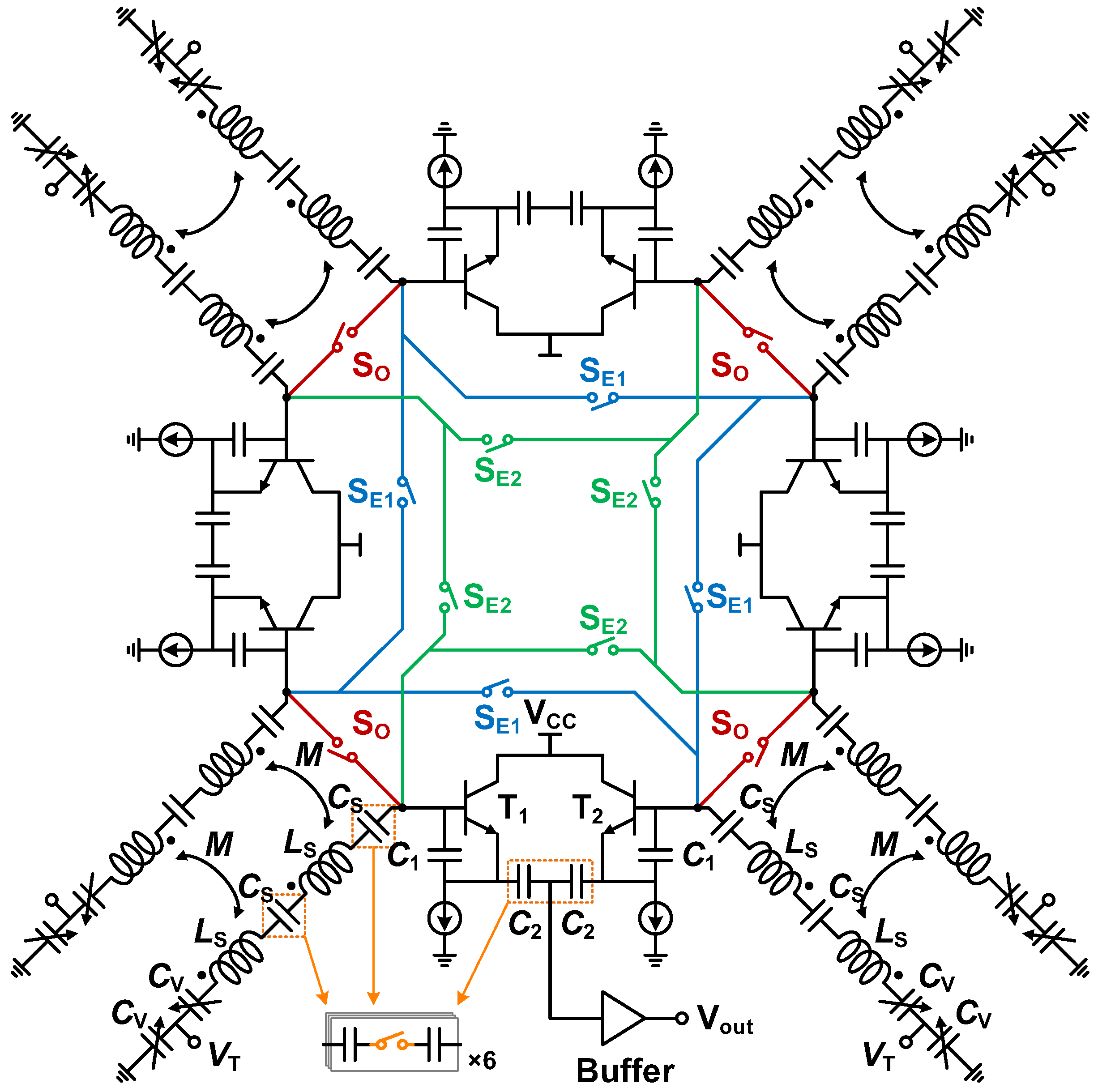
Figure 1.
Circuit diagram of proposed Colpitts VCO.
This paper is organized as follows. In Section 2, the proposed VCO structure is described and analyzed. In Section 3, the implementation of coupled inductors and mode-switching circuits is described. The post-layout simulation results and comparison with state-of-the-art VCOs are summarized in Section 4. Finally, conclusions are given in Section 5.
2. Proposed VCO Architecture
The schematic of the proposed Colpitts VCO is shown in Figure 1. The VCO consists of four coupled Colpitts VCO cores, which are symmetrically distributed. The inductors of the adjacent cores are magnetically coupled together. The four cores are electrically coupled by switches, which can achieve mode-switching operation.
2.1. Frequency Tuning Series Resonator
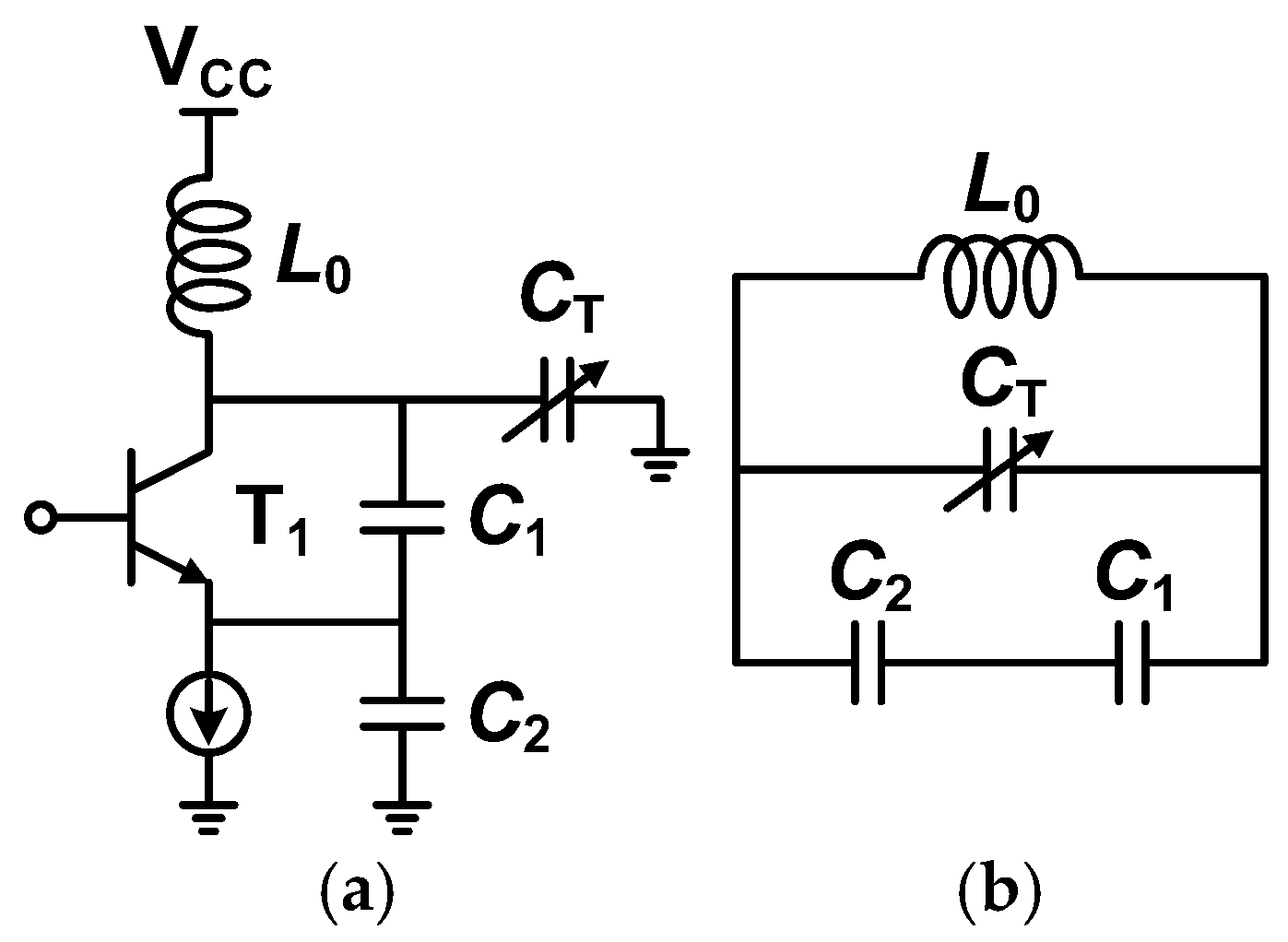
The common-collector Colpitts VCO with a frequency tuning series resonator is shown in Figure 2a, where L is the resonant inductor, C1 and C2 are fixed capacitors, and CT is the variable capacitor. Furthermore, the simplified resonant circuit of this Colpitts VCO can be obtained, as shown in Figure 2b, where the parasitic capacitances of active devices are ignored. For comparison, a traditional common-base Colpitts VCO with a parallel resonator is shown in Figure 3a. Its simplified resonant circuit is given in Figure 3b.
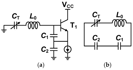
Figure 2.
Common-collector Colpitts VCO with series resonator. (a) VCO structure and (b) simplified resonant circuit.

Figure 3.
Common-base Colpitts VCO with parallel resonator. (a) VCO structure and (b) simplified resonant circuit.
For the resonant circuit in Figure 2b, the input admittance Yin can be expressed as follows:
where C0 is the equivalent capacitance of . The VCO oscillates at since the oscillation frequency can be expressed as follows:
Assuming that the maximum and minimum capacitances of the variable capacitor CT are Cmax and Cmin, respectively, the maximum and minimum oscillation frequencies of ωmax and ωmin can be obtained as follows:
The frequency tuning range (TR) is defined as follows:
It is defined that and where n represents the capacitance tuning ratio of CT, and TR can be calculated as follows:
Thus, ωmax and ωmin can be rewritten as follows:
Similarly, for the resonant circuit in Figure 3b, the input admittance Yin can be expressed as follows:
where C0 is the equivalent capacitance of . From the oscillation condition of , the oscillation frequency can be expressed as follows:
It is defined that and , and TR can be calculated as follows:
Thus, ωmax and ωmin can be written as follows:
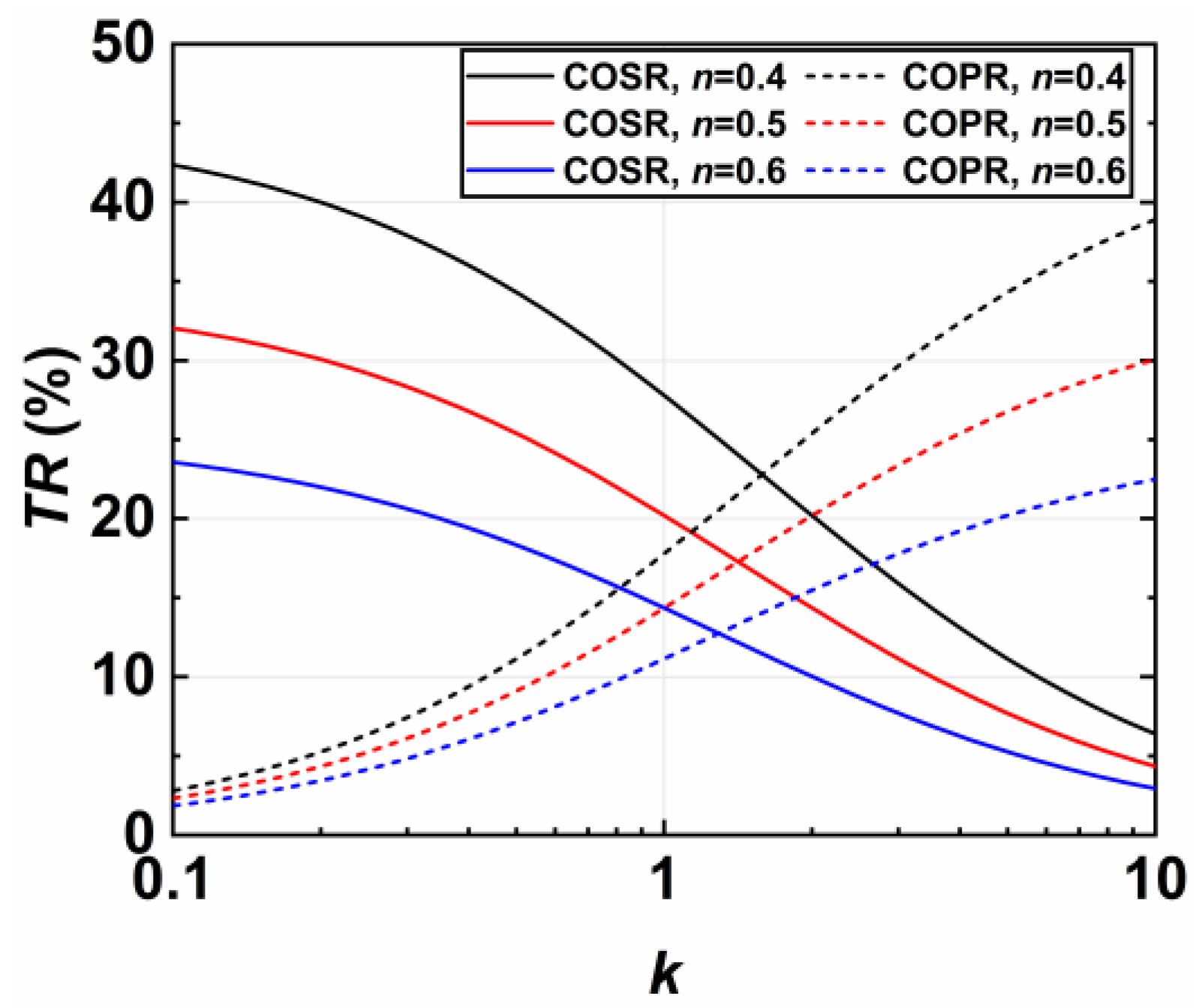
For different values of n, TR changes with respect to k, which is shown in Figure 4. For the Colpitts oscillator with a series resonator (COSR) in Figure 2, TR decreases as k increases. For the Colpitts oscillator with a parallel resonator (COPR) in Figure 3, TR increases as k increases. Setting the appropriate k with , both oscillators can achieve a TR of more than 30%. In addition, the TR upper limit of COSR is slightly higher than that of COPR.
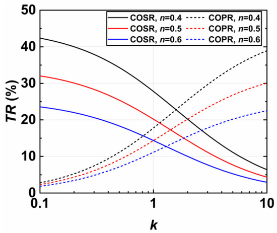
Figure 4.
TR varies with k for different n in COSR and COPR.
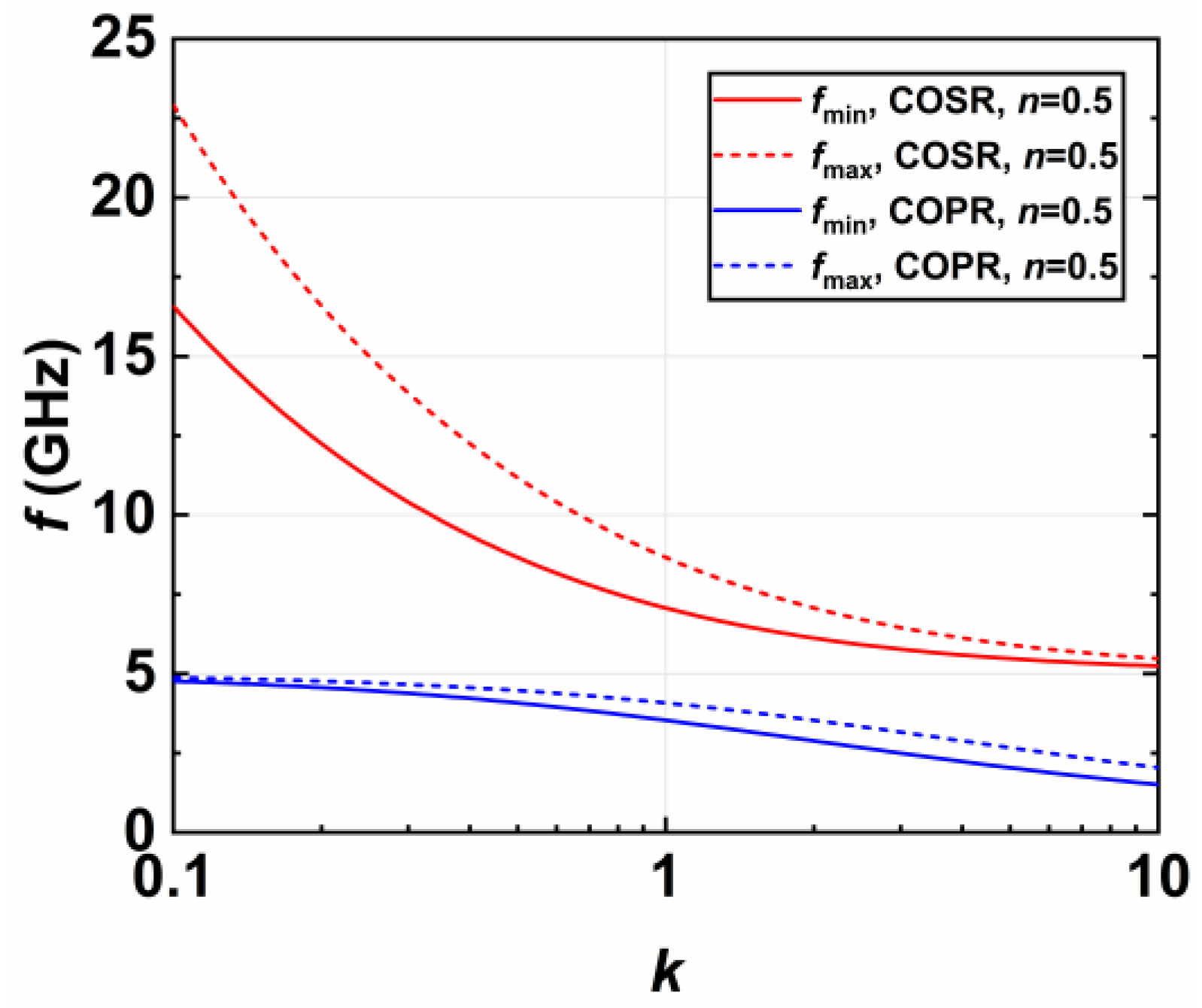
For a specific example of , , and , the oscillation frequencies of COSR and COPR versus k is exhibited in Figure 5. The fundamental oscillation frequency of f0 without considering CT can be calculated as follows:
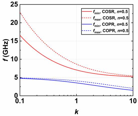
Figure 5.
Oscillation frequencies vary with k for , , and in COSR and COPR.
As k changes, the oscillation frequency is always higher than f0 in COSR. On the contrary, the oscillation frequency is always lower than f0 in COPR. In combination with Figure 4, the TR of COPR increases as k increases, but the oscillation frequency decreases continuously. Therefore, in order to increase the TR of COPR, the oscillation frequency is limited. For Colpitts oscillators, the oscillation frequency is degraded due to the more parasitic parameters. In COPR, the use of parallel resonators aggravates this issue.
In COSR, both TR and the oscillation frequency increase as k decreases. With a lower value of k, wide TR and high oscillation frequency can be achieved simultaneously. For example, using switched capacitor arrays, can be realized easily. If setting k to 0.7, the TR is calculated as 31.4%, and the oscillation frequency ranges from 7.84 to 10.76 GHz. If setting k to 0.5, the TR is calculated as 34.3%, and the oscillation frequency ranges from 8.72 to 12.33 GHz. Therefore, COSR is able to achieve a wider TR and a higher oscillation frequency compared with COPR.
In varactor-tuned VCOs, the amplitude noise translates into phase noise due to the AM/PM conversion, resulting in phase noise deterioration. The AM/PM conversion effect can be quantified by a conversion coefficient given as follows:
where ∆ω is the frequency variation resulting from the amplitude variation ∆A. Under this definition, the phase noise spectrum can be indicated as follows:
where SAM(ωm) is the power spectral density of the amplitude noise at ωm offset from the carrier. Notably, varactors with steeper tuning characteristics can improve TR while they may introduce higher AM/PM noise conversion. From previous work [18,19], KAM/PM increases as A increases, causing the phase noise to deteriorate, as shown by A2 in Equation (13). Therefore, these characteristics limit the use of steep tuning varactors in low-phase-noise VCOs.
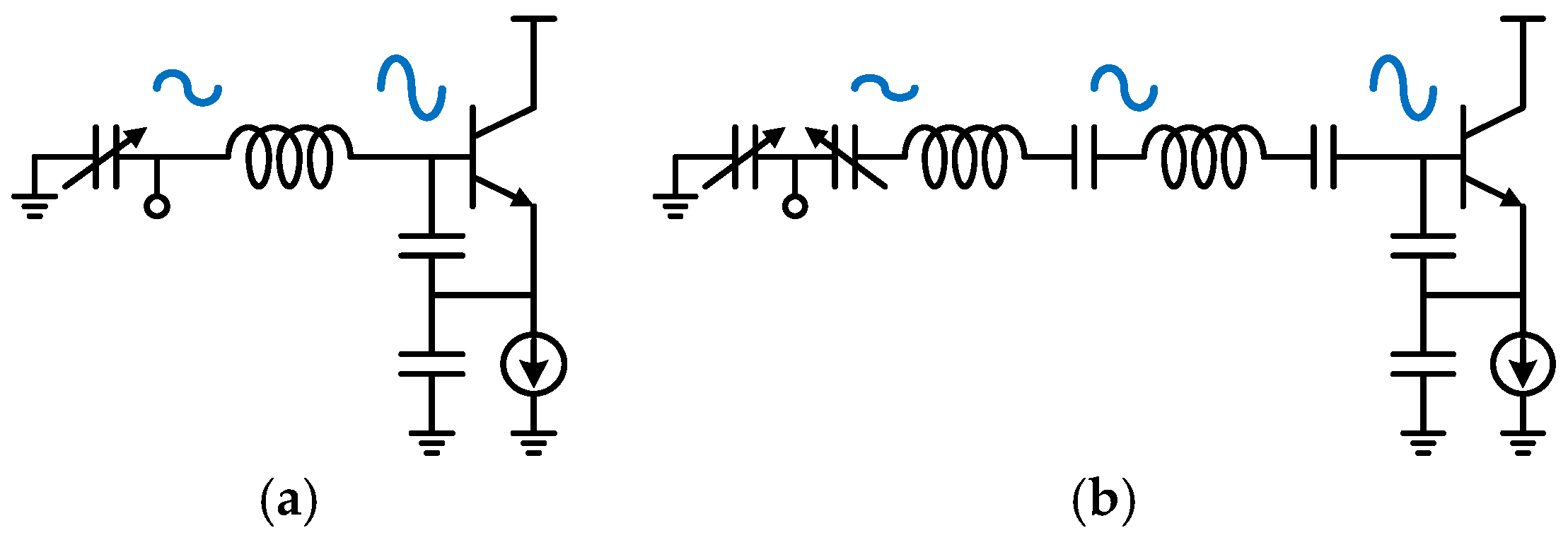
In the proposed Colpitts VCO, the back-to-back varactors were placed at the end of the presented multi-stage LC resonator, which is away from the active circuit. With this structure, the oscillation voltage applied to the varactors can be reduced compared with conventional Colpitts VCO, which reduces the deterioration of phase noise [19]. Meanwhile, using multi-stage switched capacitor banks can expand the tuning range and avoid the breakdown of MOS switches by high-oscillation voltage. The comparison of oscillation voltage amplitudes is shown in Figure 6.
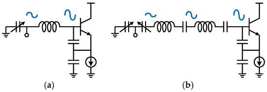
Figure 6.
Distribution of oscillation voltage amplitude of (a) conventional VCO and (b) proposed VCO.
2.2. Quad-Core Dual-Mode Switching
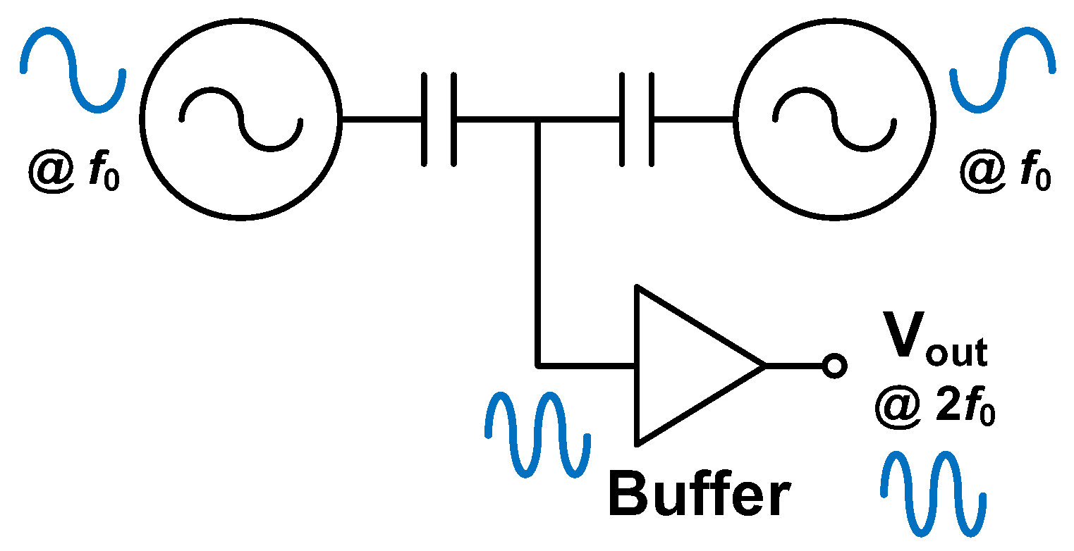
The proposed multi-stage series resonator introduces more parasitic capacitors, which limit the oscillation frequency and tuning range. To alleviate this issue, the push–push VCO structure is employed, which is shown in Figure 7. The balanced Colpitts VCO operates at a frequency of f0. The second harmonic of the 2f0 output is taken from the virtual ground node, where the fundamental frequency of f0 is canceled. For maximum power transfer and better isolation, the buffer is optimized at the frequency of 2f0.
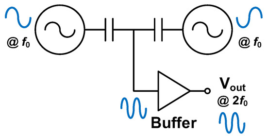
Figure 7.
Push–push VCO structure.
From the Leeson formula [33], the phase noise of VCOs can be depicted as follows:
where k is the Boltzmann constant, T is the absolute temperature, V0 is the oscillation amplitude, R is the tank resistance, and Q is the tank quality factor. In N-core coupled VCOs, R is scaled down by N times, and other parameters remain constant. Thus, the quad-core structure is used in the proposed Colpitts VCO, which theoretically introduces phase noise improvement by 6 dB compared with the single-core VCO.
Based on the quad-core coupled structure, mode-switching is achieved by driving the series resonator to operate in an even or odd mode. As shown in Figure 1, when SE is on and SO is off, the current in coupled inductors LS of adjacent cores is in the same direction, exhibiting an equivalent inductance of . On the contrary, when SE is off and SO is on, the current in LS is in the opposite direction, with an equivalent inductance of . The voltage waveform in a different mode is shown in Figure 8 and the resonant frequencies of the series resonator in even and odd modes, respectively, are given as follows:
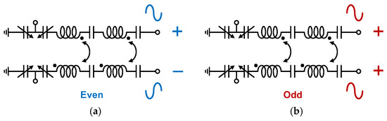
Figure 8.
Voltage waveform in (a) even mode and (b) odd mode.
Additionally, CS is designed as a switched capacitor bank, which can expand the tuning range. CV is used for continuous frequency tuning. Based on these techniques, the designed Colpitts VCO can realize an octave tuning range.
3. Design and Implementation
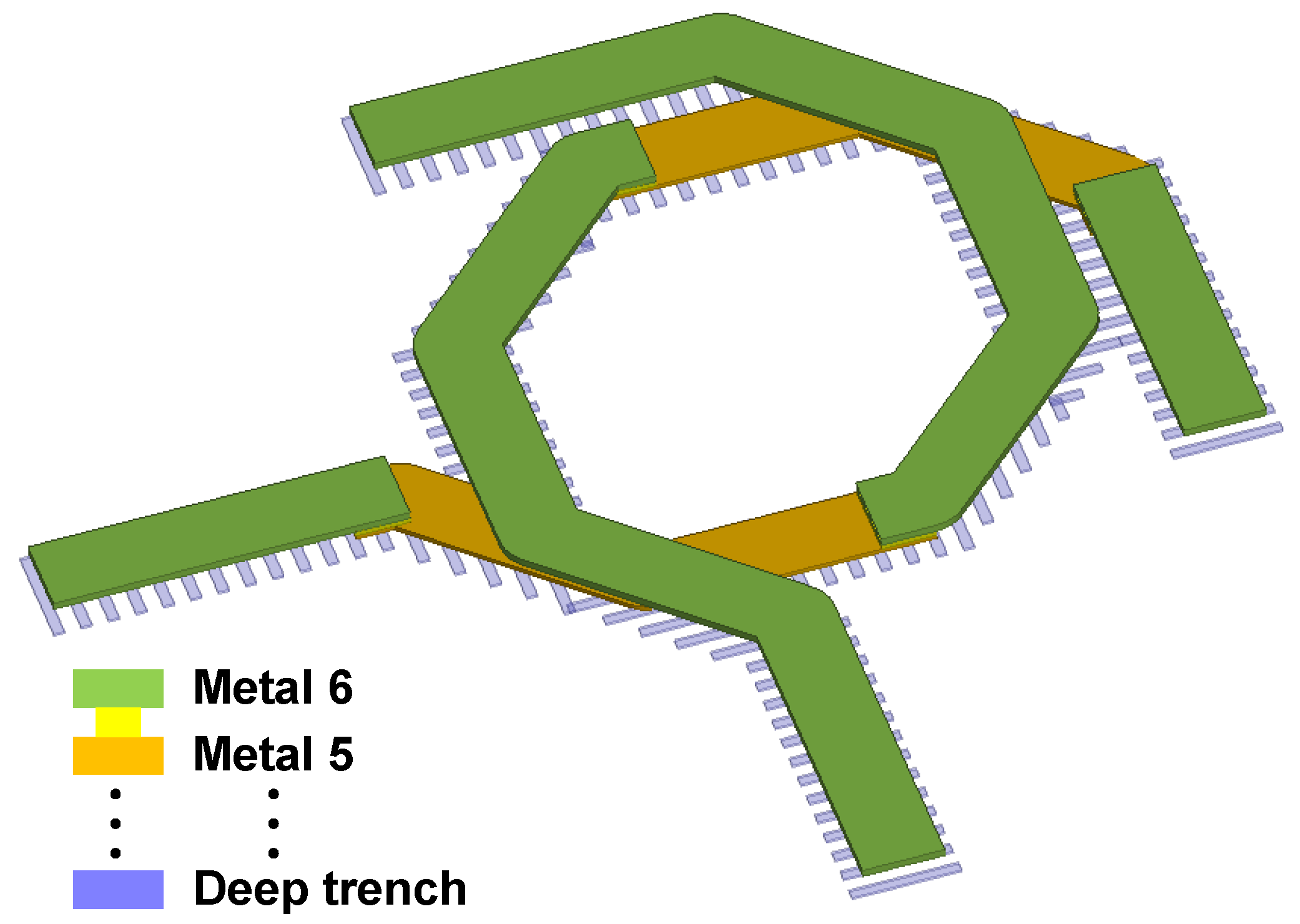
As shown in Figure 9, the designed coupled inductors are routed with the top thick metal layer primarily, which minimizes the resistance loss. The inner diameter of the inductor is 240 μm, with a width of 30 μm. The overlap between the two inductors is 180 μm. In addition, the substrate under the routing is filled with a deep-trench shield, which can reduce the substrate loss. The inductors are modeled and simulated in Ansys HFSS.
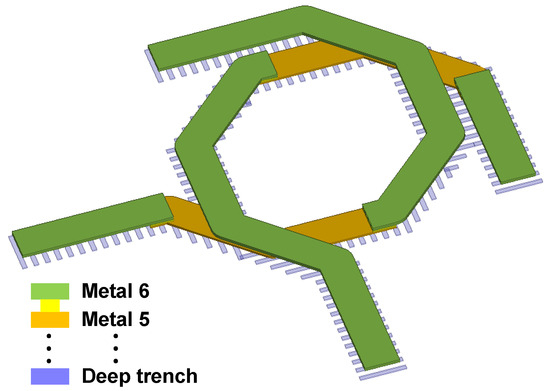
Figure 9.
Layout of designed coupled inductors.
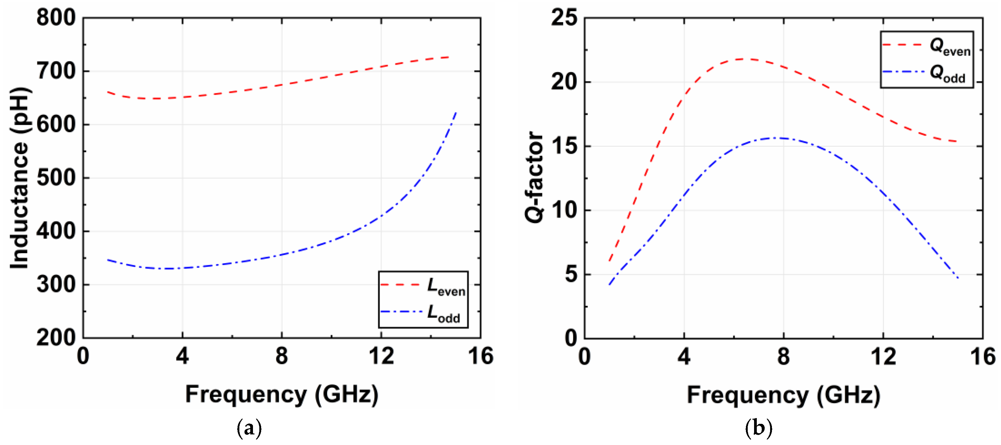
The simulated equivalent inductance and Q-factor of the coupled inductors are shown in Figure 10. Over the operating frequency, the equivalent inductance is about 660 and 330 pH in the even and odd modes, respectively. The peak Q-factor is about 22 in the even mode and about 15 in the odd mode.
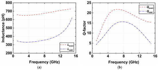
Figure 10.
Coupled inductor simulation for (a) inductance and (b) Q-factor.
Mode-switching oscillators usually suffer the issue of parasitic oscillation [11]. To achieve stable mode-switching and avoid concurrent oscillation, the switches of SE and SO, used for the coupling between the VCO cores, need to force these cores to oscillate in the even or odd mode independently.
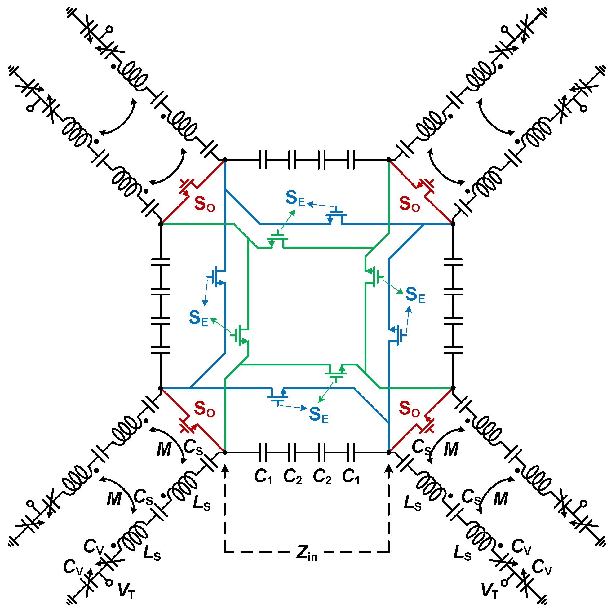
Figure 11 shows the simplified resonant circuit of the presented VCO, which consists of four resonators and MOSFET switches for mode-switching. Stable mode-switching can be realized by NMOS switches, which exhibit less ON-resistance and OFF-capacitance.
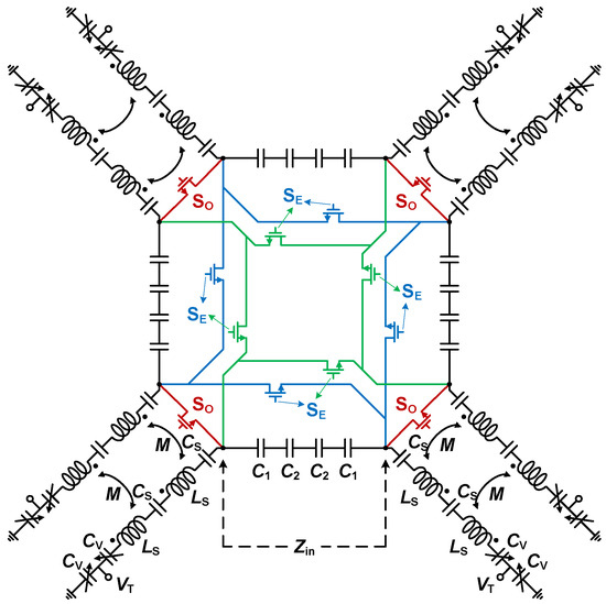
Figure 11.
Simplified resonant circuit of proposed VCO.
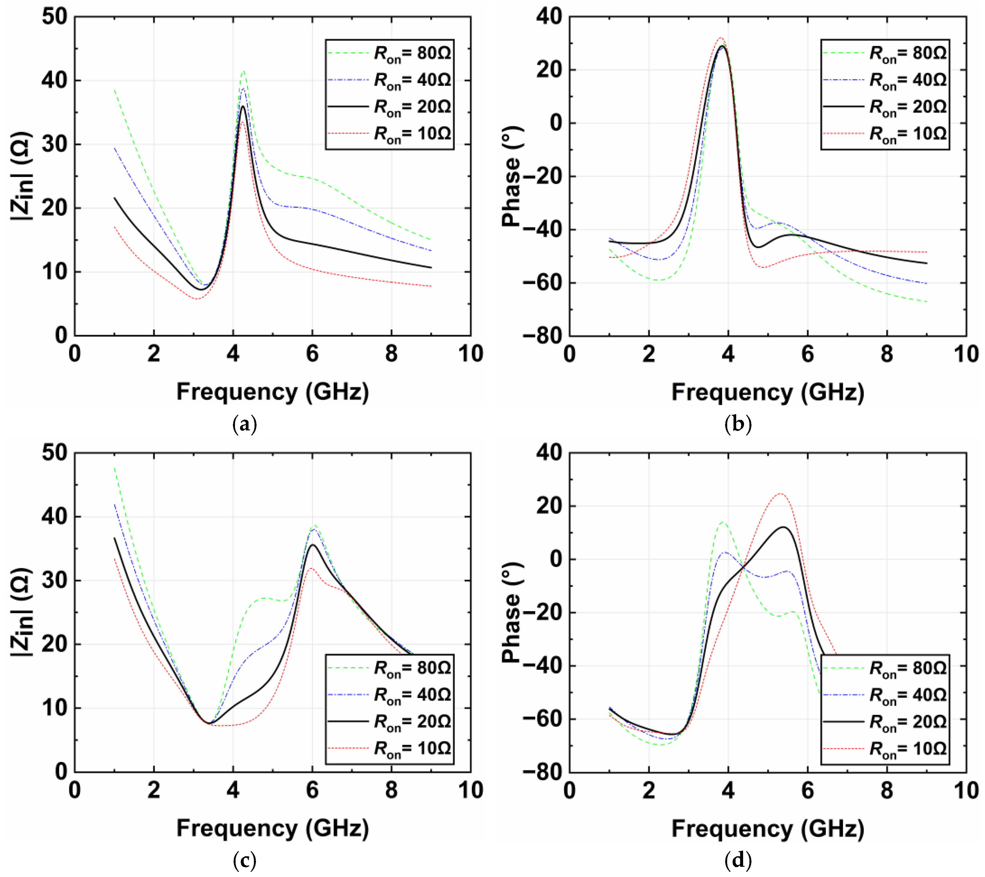
The input impedance Zin of the resonant circuit with NMOS switches of different sizes is simulated and shown in Figure 12. The oscillation operates at the frequency where the phase of the resonant circuit is zero. Notably, there are two resonance points, where one is the series resonance of the series resonator, and the other is the parallel resonance of the series resonator and the feedback capacitors of C1 and C2. The oscillation operates at the parallel resonance point. For the even mode shown in Figure 12a,b, Zin increases as Ron increases, and the oscillation state remains stable. For the odd mode shown in Figure 12c,d, the oscillation state gradually stabilizes as Ron decreases. However, MOS switches with a large size and small ON resistance introduce large OFF capacitance, which may degrade the tuning range. Considering this trade-off, NMOS switches with small ON resistance and OFF capacitance are used for mode-switching rather than PMOS or CMOS. For the switching oscillation mode, the strong coupling by ON-NMOS excites the desired mode and avoids the effects of charge injection.
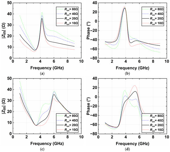
Figure 12.
Simulated input impedance (a) |Zin| in even mode; (b) phase response in even mode; (c) |Zin| in odd mode; and (d) phase response in odd mode.
The NMOS switches are set with the W/L size of 36 μm/0.18 μm, corresponding to an Ron of about 20 Ω. When switching between the two modes, only one oscillation mode is excited, and the other is suppressed, which ensures the high stability of oscillation.
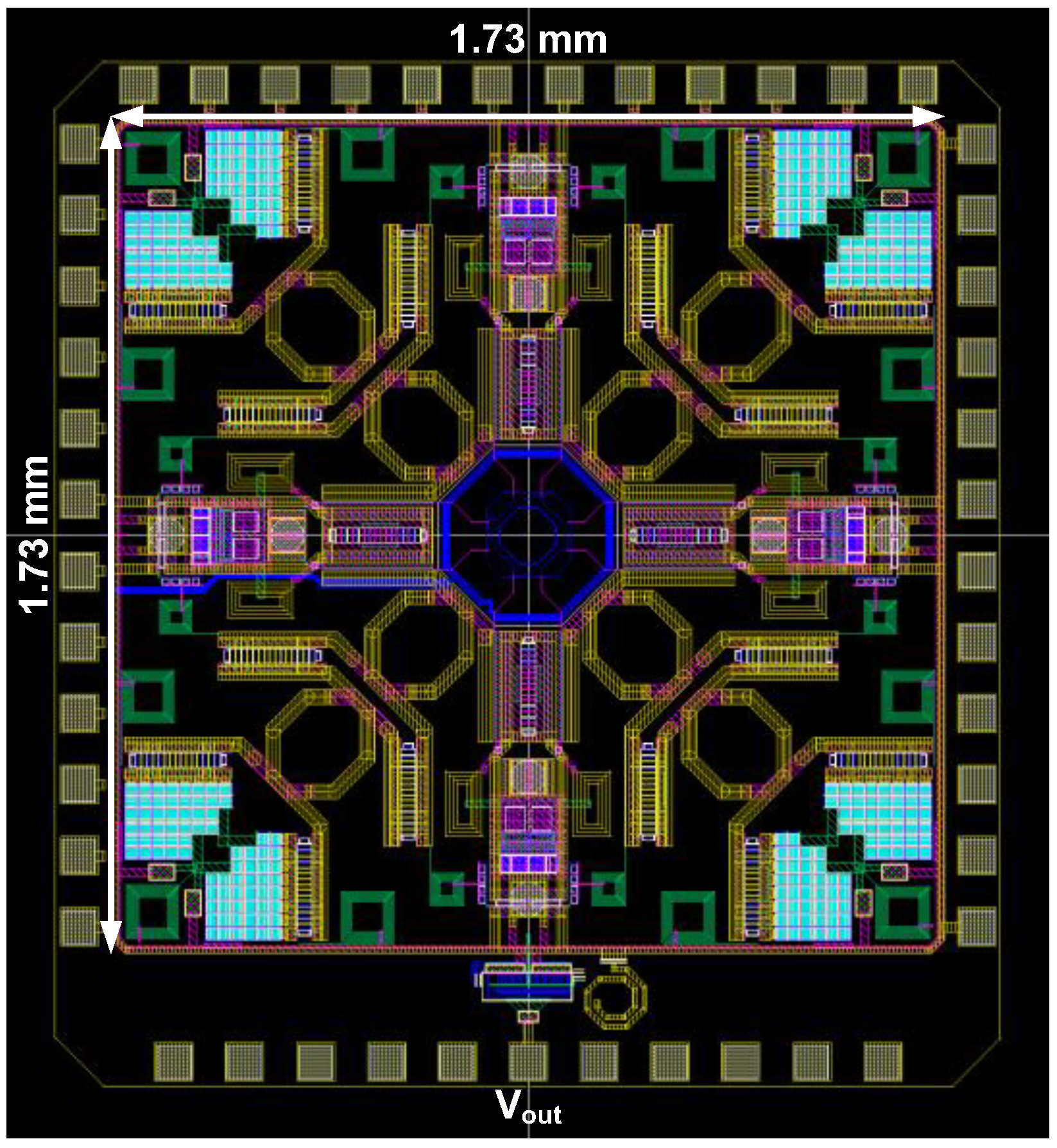
For further verification, a quad-core dual-mode Colpitts VCO was designed in the Tower Semiconductor (Newport Beach, CA, USA) 180 nm SiGe BiCMOS process with six metal layers. This process showed stable performance and accurate device models, which can fully validate the proposed method and design. The layout of the VCO chip is shown in Figure 13, and the core area of the chip is 3.0 mm2.
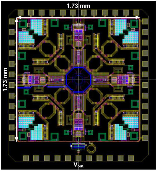
Figure 13.
Layout of designed VCO chip.
4. Simulation Results and Comparison
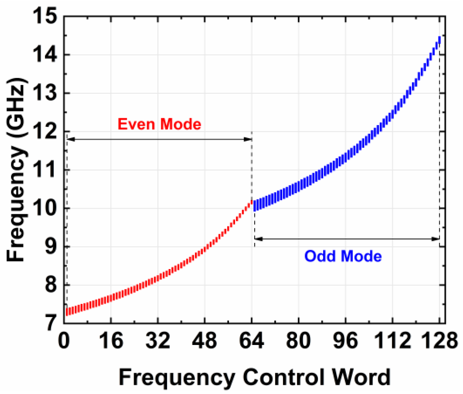
The post-layout performances were simulated in Cadence Virtuoso, and the simulation results are described as follows. The designed VCO operates from 7.2 to 14.5 GHz with a frequency tuning range of 67.3%. As shown in Figure 14, the oscillation frequency ranges from 7.2 to 10.2 GHz with a 34.5% bandwidth in the even mode (low band, LB) and from 9.9 to 14.5 GHz with a 37.7% bandwidth in the odd mode (high band, HB). The proposed Colpitts VCO achieves more than 30% bandwidth in each mode, which benefits from the proposed COSR structure. There are 64 frequency sub-bands in each mode, which results from the six-bit switched capacitor banks. The varactor tuning voltage is tuned from 0 to 3.3 V for continuous frequency tuning in each sub-band.
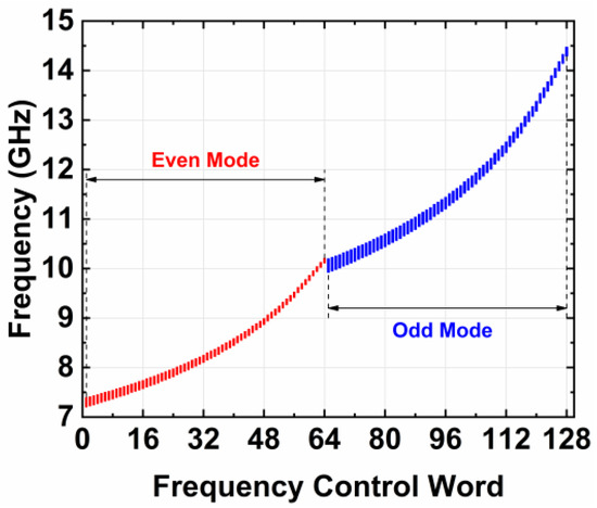
Figure 14.
Oscillation frequency range.
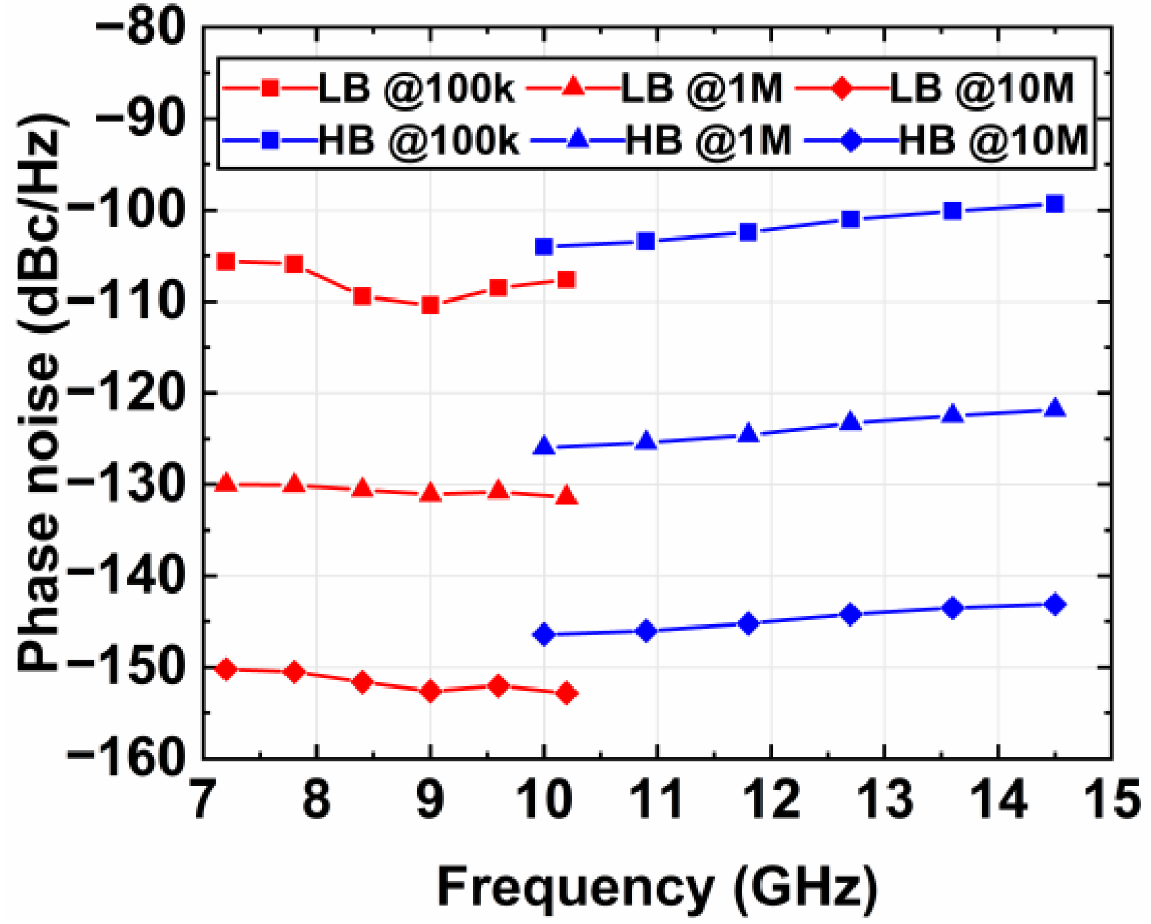
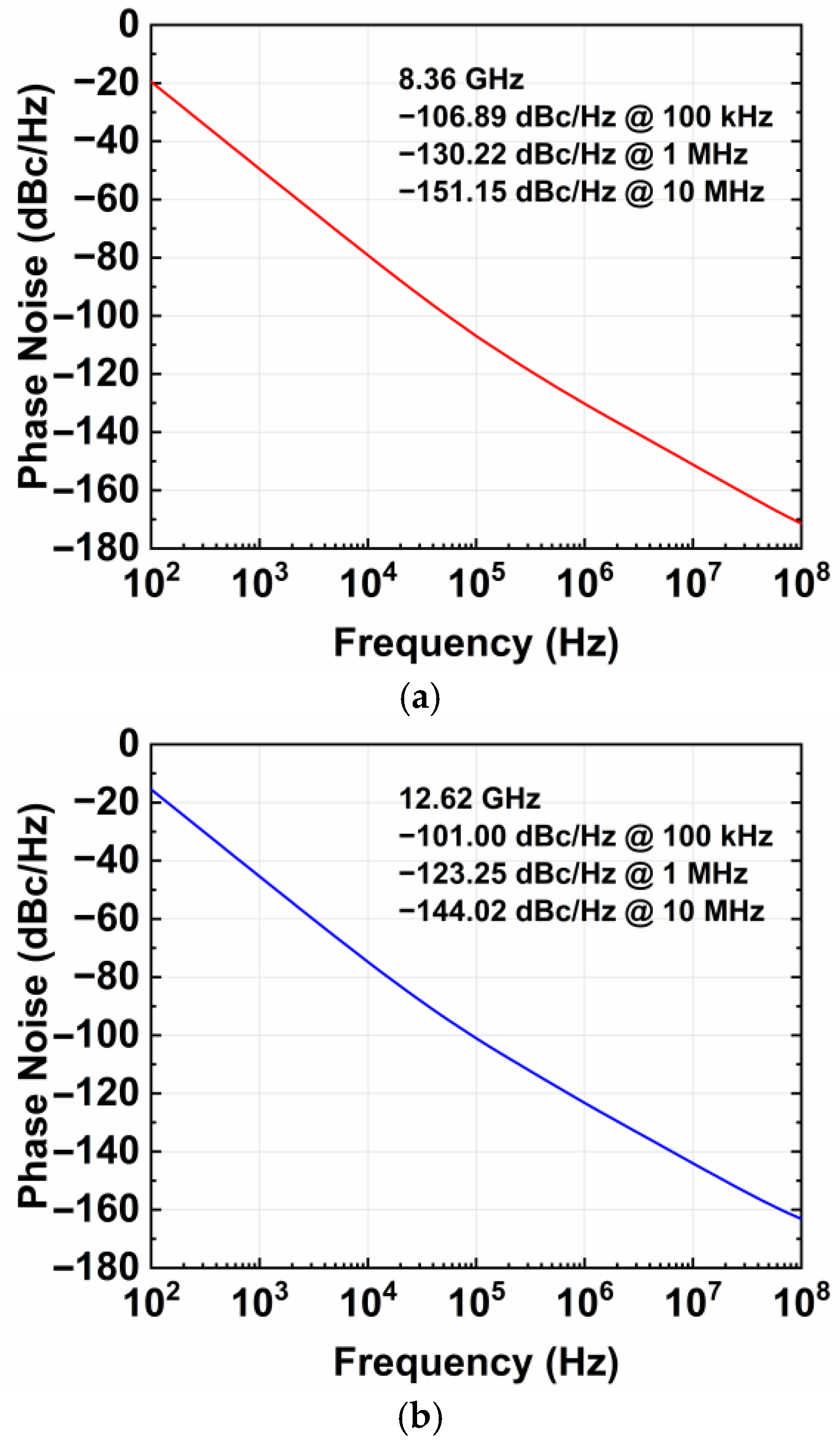
The phase noise at different oscillation frequencies is exhibited in Figure 15. Over the operating frequencies, the phase noise ranges from −110.4 to −99.3 dBc/Hz at a 100 kHz offset, from −131.4 to −121.8 dBc/Hz at a 1 MHz offset, and from −152.8 to −143.1 dBc/Hz at a 10 MHz offset. The typical phase noise at 8.36 GHz in the even mode and at 12.62 GHz in the odd mode are shown in Figure 16.

Figure 15.
Phase noise at different oscillation frequencies.
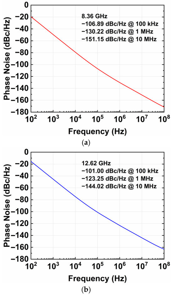
Figure 16.
Typical phase noise at (a) 8.36 GHz in even mode and (b) 12.62 GHz in odd mode.
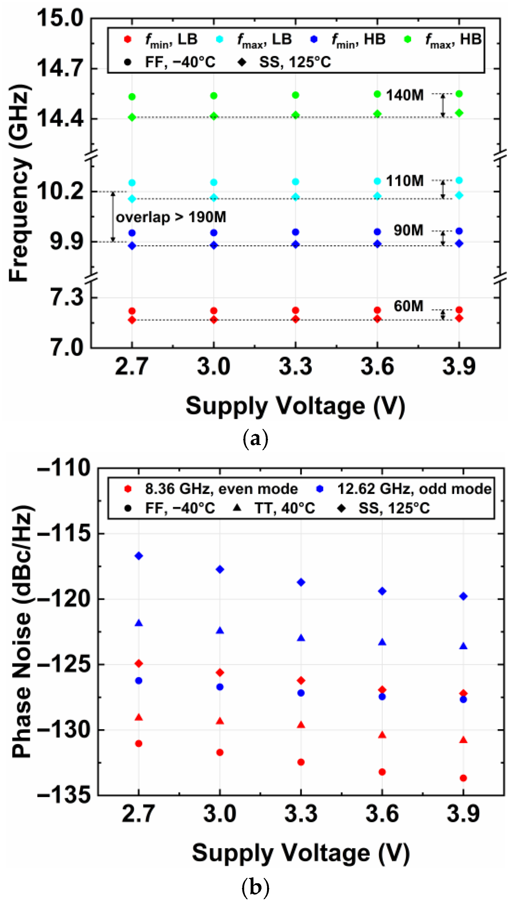
The process–voltage–temperature (PVT) simulation results for the oscillation frequency and phase noise are shown in Figure 17. The results show that the frequency variation is <140 MHz over all the operating frequencies. The minimum frequency overlap between the two oscillation modes is 190 MHz. The maximum phase noise variation is 8.7 and 10.9 dB at 8.36 and 12.62 GHz, respectively.
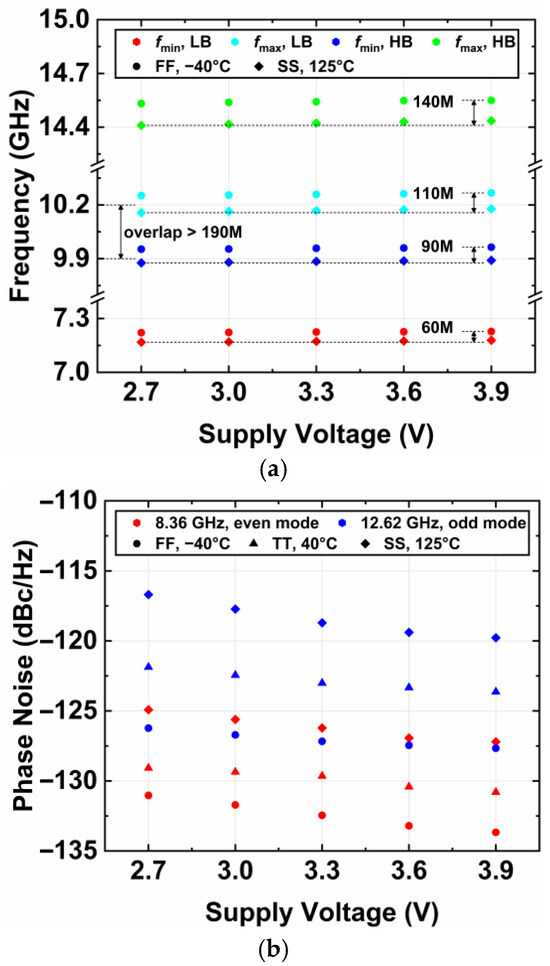
Figure 17.
PVT simulation results for (a) oscillation frequency and (b) phase noise.
The current consumption of the VCO core is 200–220 mA with a 3.3 V supply voltage, resulting in a power consumption of 660–726 mW. The figure-of-merit (FoM) ranges from 176.8 to 183.0 dBc/Hz at a 1 MHz offset. Taking the tuning range into account, the figure-of-merit-tuning (FoMT) ranges from 193.3 to 199.5 dBc/Hz at a 1 MHz offset.
The performance of the designed Colpitts VCO and its comparison with the state of the art are summarized in Table 1. Compared with the reported multi-mode wideband VCOs [1,6,10], the proposed VCO exhibits lower phase noise. Compared with the reported ultra-low phase noise VCOs [14,15,17,29], the proposed VCO has significant advantages in the tuning range. If power consumption is excluded from the FoMT, the designed VCO exhibits remarkable absolute performance for the phase noise and tuning range.

Table 1.
Performance summary and comparison with state-of-the-art VCOs.
The proposed Colpitts VCO is valuable for some specific applications that strongly need low phase noise and a wideband rather than low-power consumption and small chip areas, such as high-performance radars, precision measurement and testing equipment, and high-speed high-precision ADCs/DACs. Furthermore, to the best of the authors’ knowledge, it is the first time that the Colpitts VCO has realized an octave tuning range along with 3.3 V of the supply voltage and tuning voltage.
5. Conclusions
In this paper, a quad-core dual-mode Colpitts VCO with low phase noise and a wide frequency tuning range is presented. A quad-core coupled structure was employed for phase noise improvement. To expand the tuning range, coupled inductors and mode-switching circuits based on quad-core structures were proposed to achieve dual-mode operation. The presented series resonator effectively expands the tuning range and reduces the oscillation voltage applied to the varactors, which reduces phase noise degradation. Meanwhile, the adopted push–push structure increases the output frequency. Designed in a 180 nm SiGe BiCMOS process, the Colpitts VCO operates from 7.2 to 14.5 GHz with an octave tuning range of 67.3%. At a 1 MHz offset, the phase noise ranges from −131.4 to −121.8 dBc/Hz with a peak FoM of 183.0 dBc/Hz and FoMT of 199.5 dBc/Hz. The proposed VCO can be used for wideband ultra-low phase noise applications.
Author Contributions
Conceptualization, S.Q.; methodology, S.Q.; writing—original draft preparation, S.Q.; writing—review and editing, S.X., R.D., G.W. and L.Z. All authors have read and agreed to the published version of the manuscript.
Funding
This research received no external funding.
Data Availability Statement
The data presented in this study are available upon request from the corresponding author.
Conflicts of Interest
The authors declare no conflicts of interest.
References
- Kang, Z.; Yu, C.; Wu, L. 19.3 An 8.9-to-21.9 GHz Single-Core Oscillator with Reconfigurable Class-F−1 and Enhanced-Colpitts Dual-Mode Operation Achieving 209dBc/Hz FoMT. In Proceedings of the 2024 IEEE International Solid-State Circuits Conference (ISSCC), San Francisco, CA, USA, 18–22 February 2024; pp. 1–3. [Google Scholar]
- Kurtoglu, A.; Shirazi, A.H.M.; Mirabbasi, S.; Lavasani, H.M. An Ultra-Low-Power 65 nm Single-Tank 24.5-to-29.1 GHz Gm-Enhanced CMOS LC VCO Achieving 195.2 dBc/Hz FoM at 1 MHz. Electronics 2024, 13, 1162. [Google Scholar] [CrossRef]
- Yousef, K.; Alzahmi, A. A High FoM and Low Phase Noise Edge-Injection-Based Ring Oscillator in 350 nm CMOS for Sub-GHz ADPLL Applications. Electronics 2023, 12, 3769. [Google Scholar] [CrossRef]
- Gagliardi, F.; Manfredini, G.; Ria, A.; Piotto, M.; Bruschi, P. Low-Phase-Noise CMOS Relaxation Oscillators for On-Chip Timing of IoT Sensing Platforms. Electronics 2022, 11, 1794. [Google Scholar] [CrossRef]
- Shu, Y.; Qian, H.J.; Luo, X. 17.4 A 18.6-to-40.1 GHz 201.7 dBc/Hz FoMT Multi-Core Oscillator Using E-M Mixed-Coupling Resonance Boosting. In Proceedings of the 2020 IEEE International Solid- State Circuits Conference—(ISSCC), San Francisco, CA, USA, 16–20 February 2020; pp. 272–274. [Google Scholar]
- Ge, H.; Jia, H.; Deng, W.; Ma, R.; Wang, Z.; Chi, B. 19.5 A 13.7-to-41.5 GHz 214.1 dBc/Hz FoMT Quad-Core Quad-Mode VCO Using an Oscillation-Mode-Splitting Technique. In Proceedings of the 2024 IEEE International Solid-State Circuits Conference (ISSCC), San Francisco, CA, USA, 18–22 February 2024; pp. 356–358. [Google Scholar]
- Li, C.; Guo, J.; Qin, P.; Xue, Q. A Wideband Mode-Switching Quad-Core VCO Using Compact Multi-Mode Magnetically Coupled LC Network. IEEE J. Solid State Circuits 2023, 58, 1959–1972. [Google Scholar] [CrossRef]
- El-Aassar, O.; Rebeiz, G.M. Octave-Tuning Dual-Core Folded VCO Leveraging a Triple-Mode Switch-Less Tertiary Magnetic Loop. IEEE J. Solid State Circuits 2021, 56, 1475–1486. [Google Scholar] [CrossRef]
- Kim, H.; Kim, S.; Jeon, S. An Octave Tuning Range Quad-Core VCO Using a Compact Quad-Mode Transformer-Based Inductor. In Proceedings of the 2024 IEEE Radio Frequency Integrated Circuits Symposium (RFIC), Washington, DC, USA, 16–18 June 2024; pp. 83–86. [Google Scholar]
- Ge, H.; Jia, H.; Deng, W.; Ma, R.; Chi, B. A 194.9 dBc/Hz FoM and 6.8-to-11.6 GHz Quad-Core Dual-Mode Class-F VCO Featuring Wideband Flicker Noise Suppression. In Proceedings of the 2024 IEEE Custom Integrated Circuits Conference (CICC), Denver, CO, USA, 21–24 April 2024; pp. 1–2. [Google Scholar]
- Padovan, F.; Quadrelli, F.; Bassi, M.; Tiebout, M.; Bevilacqua, A. A quad-core 15GHz BiCMOS VCO with −124d Bc/Hz phase noise at 1MHz offset, −189 dBc/Hz FOM, and robust to multimode concurrent oscillations. In Proceedings of the 2018 IEEE International Solid-State Circuits Conference (ISSCC), San Francisco, CA, USA, 11–15 February 2018; pp. 376–378. [Google Scholar]
- Wu, Q.; Deng, W.; Jia, H.; Liu, H.; Zhang, S.; Wang, Z.; Chi, B. 8.1 An 11.5-to-14.3 GHz 192.8 dBc/Hz FoM at 1MHz Offset Dual-Core Enhanced Class-F VCO with Common-Mode-Noise Self-Cancellation and Isolation Technique. In Proceedings of the 2023 IEEE International Solid- State Circuits Conference (ISSCC), San Francisco, CA, USA, 19–23 February 2023; pp. 7–9. [Google Scholar]
- Tripoli, D.; Maiellaro, G.; Pavone, S.C.; Ragonese, E. Interstacked Transformer Quad-Core VCOs. Electronics 2024, 13, 927. [Google Scholar] [CrossRef]
- Zhang, S.; Deng, W.; Jia, H.; Chi, B. An 11 GHz 8-core Series Resonance CMOS VCO with Scalable Ring-coupling Scheme Achieving Phase Noise of -136.8 dBc/Hz at 1 MHz Offset. In Proceedings of the 2024 IEEE Radio Frequency Integrated Circuits Symposium (RFIC), Washington, DC, USA, 16–18 June 2024; pp. 95–98. [Google Scholar]
- Franceschin, A.; Riccardi, D.; Mazzanti, A. Ultra-Low Phase Noise X-Band BiCMOS VCOs Leveraging the Series Resonance. IEEE J. Solid State Circuits 2022, 57, 3514–3526. [Google Scholar] [CrossRef]
- Pepe, F.; Bevilacqua, A.; Andreani, P. On the Remarkable Performance of the Series-Resonance CMOS Oscillator. IEEE Trans. Circuits Syst. I Regul. Pap. 2018, 65, 531–542. [Google Scholar] [CrossRef]
- Zhang, S.; Deng, W.; Jia, H.; Liu, H.; Sun, S.; Guan, P.; Wang, Z.; Chi, B. A Transformer-Based Series-Resonance CMOS VCO. IEEE J. Solid State Circuits 2025, 60, 529–542. [Google Scholar] [CrossRef]
- Levantino, S.; Samori, C.; Zanchi, A.; Lacaita, A. AM-to-PM conversion in varactor-tuned oscillators. IEEE Trans. Circuits Syst. II Analog. Digit. Signal Process. 2002, 49, 509–513. [Google Scholar] [CrossRef]
- Bonfanti, A.; Levantino, S.; Samori, C.; Lacaita, A. A varactor configuration minimizing the amplitude-to-phase noise conversion in VCOs. IEEE Trans. Circuits Syst. I Regul. Pap. 2006, 53, 481–488. [Google Scholar] [CrossRef]
- Hegazi, E.; Abidi, A. Varactor characteristics, oscillator tuning curves, and am-fm conversion. IEEE J. Solid State Circuits 2003, 38, 1033–1039. [Google Scholar] [CrossRef]
- Kim, J.; Mauludin, M.F.; Azzahra, H.A.; Jhon, H.; Lee, S.; Cho, K. An 18–19.2 GHz Voltage-Controlled Oscillator with a Compact Varactor-Only Capacitor Array. Electronics 2023, 12, 1532. [Google Scholar] [CrossRef]
- Yao, Y.; Li, Z.; Li, Z.; Chen, B.; Wang, X. A 3.7-to-10 GHz Low Phase Noise Wideband LC-VCO Array in 55-nm CMOS Technology. Electronics 2022, 11, 1897. [Google Scholar] [CrossRef]
- Hajimiri, A.; Lee, T. A general theory of phase noise in electrical oscillators. IEEE J. Solid State Circuits 1998, 33, 179–194. [Google Scholar] [CrossRef]
- Ham, D.; Hajimiri, A. Concepts and methods in optimization of integrated LC VCOs. IEEE J. Solid State Circuits 2001, 36, 896–909. [Google Scholar] [CrossRef]
- Zirath, H.; Kozhuharov, R.; Ferndahl, M. Balanced Colpitt oscillator MMICs designed for ultra-low phase noise. IEEE J. Solid State Circuits 2005, 40, 2077–2086. [Google Scholar] [CrossRef]
- Quadrelli, F.; Panazzolo, F.; Tiebout, M.; Padovan, F.; Bassi, M.; Bevilacqua, A. A 18.2-29.3 GHz Colpitts VCOs bank with -119.5 dBc/Hz Phase Noise at 1 MHz Offset for 5G Communications. In Proceedings of the 2019 IEEE Radio Frequency Integrated Circuits Symposium (RFIC), Boston, MA, USA, 2–4 June 2019; pp. 167–170. [Google Scholar]
- Möck, M.; Aksoyak, İ.K.; Ulusoy, A.Ç. A Ka -Band Colpitts–Clapp VCO with 30% Tuning Range and High Output Power. IEEE Technol. Policy Ethic 2023, 33, 439–442. [Google Scholar] [CrossRef]
- Xia, X.; Cheng, X.; Chen, F.; Luo, X.; Deng, X. An Improved Colpitts VCO with Low Phase Noise Using a GaAs BiHEMT Process. IEEE Microw. Wirel. Components Lett. 2020, 30, 70–73. [Google Scholar] [CrossRef]
- Florian, C.; D’Angelo, S.; Resca, D.; Scappaviva, F. A chip set of low phase noise MMIC VCOs at C, X and Ku band in InGaP-GaAs HBT technology for satellite telecommunications. In Proceedings of the 2017 IEEE/MTT-S International Microwave Symposium—IMS 2017, Honololu, HI, USA, 4–9 June 2017; pp. 1148–1151. [Google Scholar]
- Kuylenstierna, D.; Lai, S.; Bao, M.; Zirath, H. Design of Low Phase-Noise Oscillators and Wideband VCOs in InGaP HBT Technology. IEEE Trans. Microw. Theory Tech. 2012, 60, 3420–3430. [Google Scholar] [CrossRef]
- Kashani, M.H.; Molavi, R.; Mirabbasi, S. A 2.3-mW 26.3-GHz Gm -Boosted Differential Colpitts VCO With 20% Tuning Range in 65-nm CMOS. IEEE Trans. Microw. Theory Tech. 2019, 67, 1556–1565. [Google Scholar] [CrossRef]
- Lim, C.-W.; Yun, T.-Y. Gm- and Swing-Enhanced Colpitts VCO by Optimization of Capacitance Ratio. IEEE Microw. Wirel. Compon. Lett. 2020, 20, 977–980. [Google Scholar] [CrossRef]
- Leeson, D. A simple model of feedback oscillator noise spectrum. Proc. IEEE 1966, 54, 329–330. [Google Scholar] [CrossRef]


Disclaimer/Publisher’s Note: The statements, opinions and data contained in all publications are solely those of the individual author(s) and contributor(s) and not of MDPI and/or the editor(s). MDPI and/or the editor(s) disclaim responsibility for any injury to people or property resulting from any ideas, methods, instructions or products referred to in the content. |
© 2025 by the authors. Licensee MDPI, Basel, Switzerland. This article is an open access article distributed under the terms and conditions of the Creative Commons Attribution (CC BY) license (https://creativecommons.org/licenses/by/4.0/).