Article

Method for Network-Wide Characteristics in Multi-Terminal DC Distribution Networks During Asymmetric Short-Circuit Faults

1
Electric Power Research Institute, Guizhou Power Grid Co., Ltd., Guiyang 550002, China
2
Department of Electrical Engineering, North China Electric Power University, Baoding 071003, China
*
Author to whom correspondence should be addressed.
Electronics 2025, 14(6), 1120; https://doi.org/10.3390/electronics14061120
Submission received: 10 February 2025 / Revised: 5 March 2025 / Accepted: 9 March 2025 / Published: 12 March 2025
(This article belongs to the Special Issue Efficient and Resilient DC Energy Distribution Systems)

Abstract

:
With the widespread integration of distributed energy resources and novel loads, the DC attributes of distribution networks are becoming increasingly pronounced. Multi-terminal flexible DC distribution networks have emerged as a trend for future distribution grids due to lower line losses, better power quality, etc. However, owing to their low damping and inertia, the multi-terminal flexible DC distribution network is vulnerable to DC faults. Analyzing the fault characteristics and calculating the fault current level is of great significance for the design of relay protection systems and the optimization of associated parameters. Throughout the fault process, the discharge paths of multiple converters are mutually coupled, and the fault characteristics are complex, which poses a great challenge to short-circuit calculations. This paper proposes a method for calculating the characteristic quantities of the whole network throughout the asymmetric short-circuit fault in a multi-terminal flexible DC distribution network. During the capacitor discharge stage, an equivalent model of the fault port is established before the control response. During the fault ride-through stage, a transfer matrix that takes into account the electrical constraints on both the AC and DC sides of the converters is proposed by combining the equivalent circuit of fully controlled converters. Finally, a simulation model of a six-terminal flexible DC distribution network is developed in PSCAD/EMTDC, and the simulation results demonstrate that the proposed method expands the calculation range from faulty branch to network-wide characteristic quantities throughout the process of asymmetric short-circuit faults, with the maximum relative error remaining below 5%.

1. Introduction

With the widespread adoption of renewable energy sources and the integration of various distributed energy storage systems [1,2,3], traditional AC distribution networks, known for high losses and limited flexibility, are struggling to meet the evolving demands of modern grid development [4]. In contrast, the flexible DC distribution network, as an emerging technology, has rapidly advanced in recent years, offering low energy losses, enhanced controllability, and the seamless integration of renewable sources [5,6,7]. Therefore, advancing research on protection strategies for flexible DC distribution networks is of paramount importance. The development of such protection schemes is fundamentally dependent on in-depth fault analysis and precise short-circuit current calculations. Since the flexible DC distribution network is characterized by low damping and inertia, following a DC fault, short-circuit currents escalate rapidly, resulting in high peak fault currents and severe hazards. Blocking the converter station is the simplest fault control method but it introduces uncontrollable risks to the converter, prolonging power transmission interruptions and exacerbating the impact of incidents [8]. To mitigate these issues, researchers have proposed converter fault ride-through control strategies. References [9,10] introduce the hybrid MMC-based strategy that leverages active converter control to clear fault current. Reference [11] highlights the coordinated operation of the half-bridge MMC and the DC circuit breaker, offering a robust approach to fault isolation. During this period, the progression of a DC fault in flexible DC distribution networks can be divided into the capacitor discharge stage (prior to control response) and the fault ride-through stage. However, the presence of multiple converter types in complex systems, along with numerous power electronic devices, leads to significant variability in fault characteristics across stages, exhibiting strongly coupled and nonlinear behavior, which presents considerable challenges for short-circuit current calculations [12].
Existing research on short-circuit calculation methods is predominantly centered on the capacitor discharge stage in the early phase of fault development, and most studies only involve the faulty branch. There is a relative lack of calculation methods for characteristic quantities at the ‘network’ level. Since the fault equivalent network in the capacitive discharge stage constitutes a high-order system it is difficult to solve directly [13]. Reference [14] simplifies the fault ring network before lockout to an open or two-terminal network based on the discharge path of the converter station. The maximum relative error is consistently maintained within 5%. Reference [15] further analyzes the coupling discharge mechanism of each converter station when a non-metallic fault with fault resistances occurs and decouples calculation by defining an equivalent gain coefficient. The error decreases to one-sixth of the value without decoupling. In Reference [16], using the two-port equivalent model of the faulted DC line, the key factors determining short-circuit current magnitude are analyzed. The ring-shaped DC network is simplified into a two-terminal network and an open-loop network to streamline calculations. However, these methods rely on simplifying the ring network to an open-loop equivalent and do not comprehensively consider the feed current from healthy branches, and the maximum relative error is confined to less than 10%, hindering the accurate calculation of network-wide characteristic quantities. Reference [17] introduces a short-circuit current calculation method for long-distance transmission lines by considering their distributed parameters. Nevertheless, it is unsuitable for short-line multi-terminal distribution networks, as using a lumped parameter model introduces an error of around 10%, leading to a reduction in accuracy. Consequently, enhanced fault ride-through capabilities are now essential for converters to maintain system security and stability. Following the occurrence of a fault, the coordinated operation of DC circuit breakers or self-clearing converters with protection mechanisms effectively limits the fault current, marking the transition from the capacitor discharge phase to the fault ride-through stage. During this stage, the AC and DC sides of the converter are strongly coupled. Accurate modeling of the converter is critical for short-circuit calculation [18,19]. Reference [20] develops continuous and discrete-time models for the grid-connected MMC. Reference [21] develops equivalent models for the MMC in blocked and non-blocked states, solving the short-circuit current via differential equations. Yet, neglecting the AC/DC side coupling effects leads to a maximum error of 0.91 kA. In Reference [22], a short-circuit current calculation method for flexible DC distribution networks is proposed, but it is only applicable to symmetrical faults. Reference [23] utilizes a high-frequency equivalent model to formulate node voltage and short-circuit current equations for DC fault scenarios in a simplified circuit, maintaining a maximum error of 4%. However, the model’s accuracy, while high at the fault inception, progressively decreases with time. Most of these approaches overlook converter fault analysis and do not consider network-wide characteristic quantities during the fault ride-through process. Overall, practical methods for calculating network-wide characteristic quantities during the capacitive discharge stage of asymmetrical faults require further exploration.
To this end, this paper proposes a method for calculating network-wide characteristic quantities throughout the asymmetrical short-circuit fault process. In the capacitive discharge stage, an equivalent model of the faulty network is developed to account for the coupling effects of positive and negative-pole lines. The theory of DC fault ports is introduced, and boundary conditions are applied to solve for network-wide characteristic quantities. During the fault ride-through stage, the converter transfer matrix is analytically derived by integrating AC-side and DC-side fault current characteristics. Then, based on the node voltage matrix, the network-wide characteristic quantities can be derived. Extensive simulations were performed on a six-terminal flexible DC distribution network model in PSCAD/EMTDC. The results conclusively validate the high accuracy of the proposed method and provide support for designing asymmetrical fault protection schemes for flexible DC distribution networks.

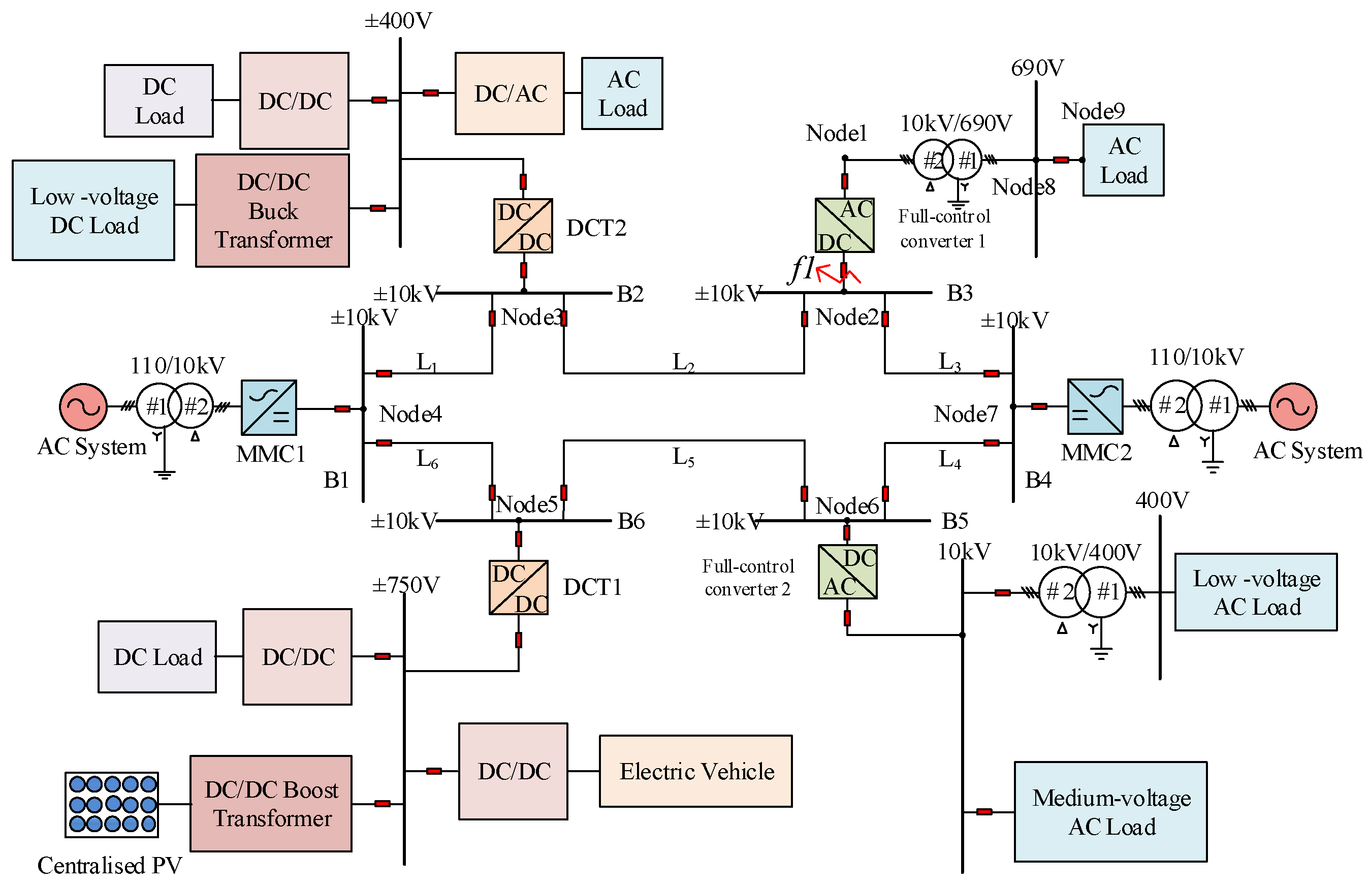
2. Materials and Methods

2.1. Equivalent Model During Capacitor Discharge Stage

A typical six-terminal flexible DC distribution network, as depicted in Figure 1, is used to analyze the fault transient characteristics in this paper. In the system, the MMC1 (Modular Multilevel Converter) converter station employs constant DC voltage control, the MMC2 converter station uses constant power control, the DCT (DC Transformer) converter stations adopt single-phase shift control, and the VSC (two/three-level Voltage Source Converter) converter stations implement constant AC voltage control. All MMCs use half-bridge submodules.

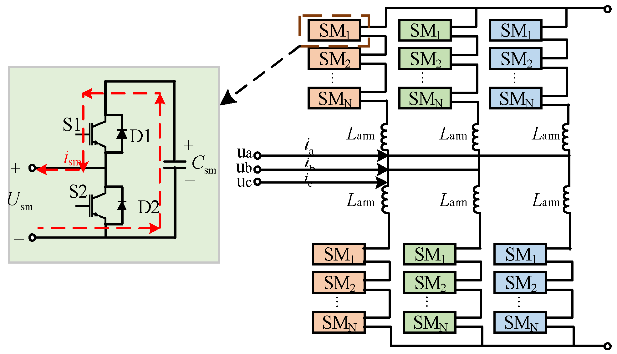
2.1.1. Equivalent Models of Converters

In simplified fault current calculations, VSCs and DCTs can be modeled as large capacitors, as shown in Figure 2, where Cs is the DC side shunt capacitor.
The basic topology of the MMC is illustrated in Figure 3. During the capacitor discharge stage, the MMC converter can be equivalent to an RLC series circuit, as shown in Figure 4a. However, considering the voltage-equalizing function of the bridge arm, the equivalent capacitance (Ceq) of each phase unit needs to be derived based on energy conservation principles [24], as shown in Equation (1):
2 N × 1 2 C sm U sm 2 = 1 2 C eq ( N U sm ) 2
where Csm represents the capacitance of a single submodule, Usm is the submodule voltage, N is the number of submodules in the bridge arm, Larm is the inductance of a single-phase bridge arm, and Rarm is the on-state resistance of a single-phase bridge arm switch.
Since the parameters of the three-phase bridge arm of the MMC are symmetrical, they can be further simplified using circuit theorems to obtain equivalent parameters, as shown in Equation (2).
R m = 2 R arm / 3 L m = 2 L arm / 3 C m = 3 C eq
where Rm, Lm, and Cm are the equivalent resistance, inductance, and capacitance values of the MMC, respectively. The equivalent model of MMCs before the control response is depicted in Figure 4b.

2.1.2. Equivalent Model of DC Lines

Considering the electromagnetic coupling between positive and negative lines, the pole components must be decoupled into independent modulus components through pole-mode transformation as Equation (3).
  X 0 X 1 = 1 2 1 1 1 1 X p X n
where X0 and X1 represent the 0-mode and 1-mode components, while Xp and Xn denote the positive and negative components, respectively. The 0-mode components have the same magnitude and polarity, forming a loop with the earth, also known as the ground-mode component. Conversely, the 1-mode components have equal magnitudes but opposite polarities, forming a loop between the positive and negative poles, and is referred to as the line-mode component. The final line impedance parameters are given in Equation (4).
R 0 = R s L 0 = L si + L mi R 1 = R s L 1 = L si L mi
where Rs is the line equivalent resistance, Lsi is the line self-inductance parameter, and Lmi is the line mutual inductance. R0 and R1 are the 0-mode and 1-mode resistance values, while L0 and L1 are the 0-mode and 1-mode inductance values, respectively.
In the analytical calculation of the fault current, the following simplifications are commonly applied in addition to the converters and DC lines:
(1)
Due to the short transmission distance in a medium-voltage DC distribution network and its low sensitivity to frequency-varying parameters, this paper uses the lumped parameter model for the line, which can not only accurately describe the change of fault current but also simplify the process of solving.
(2)
During the initial fault stage, short-circuit current is primarily supplied by the discharge current of converter stations. Due to the symmetrical configuration of the three-phase system on the AC side, it merely provides current continuity through the bridge arm and does not directly supply power to the fault point. Therefore, the influence of the AC side current can be approximately ignored during the capacitor discharge stage [25].
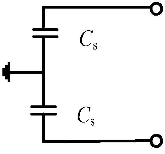
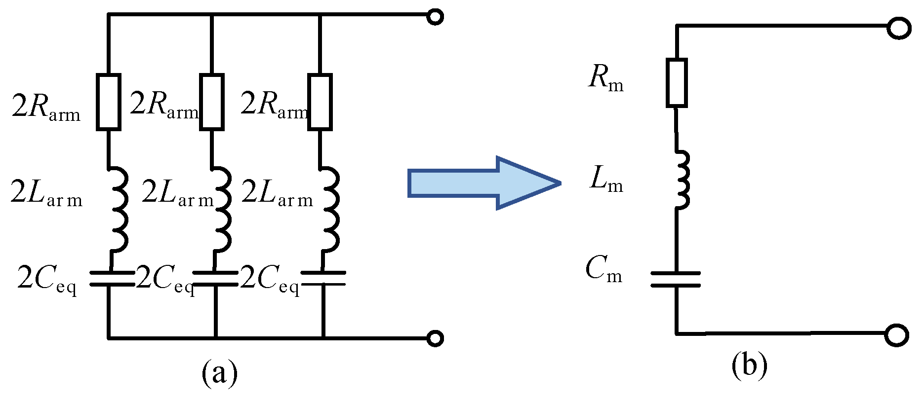
(3)
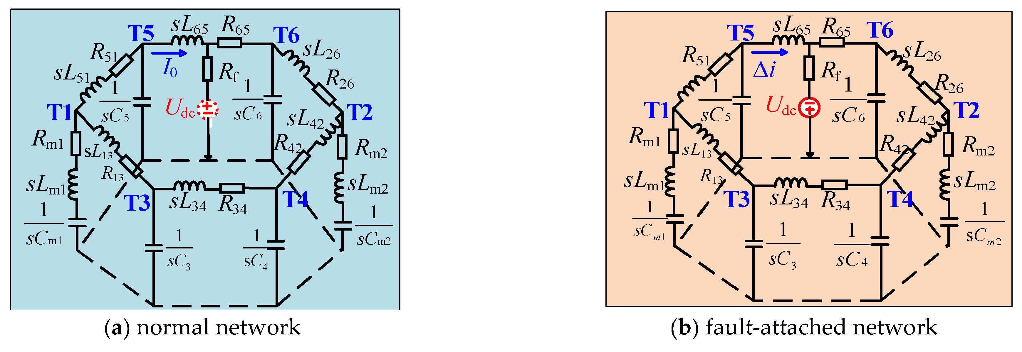
In the early capacitor discharge stage (within 2 ms), the short-circuit current can be regarded as the superposition of high-frequency signals. The impedance of the capacitor in the high-frequency band approaches zero. Considering the high-frequency characteristics of the impedance, the equivalent fault model in this phase can be simplified to a resistance–inductance network [14].
Finally, the equivalent models for the normal network and the fault-attached network at the fault location f1 are established, as shown in Figure 5a and Figure 5b, respectively.
Where, R i j represents the equivalent resistance of the line, s L i j represents the sum of the equivalent reactance of the line and the limiting reactance (i, j = 1∼6); R m k , L m k , and C m k represent the equivalent parameters of each converter station (k = 1∼6); I 0 is the current during normal system operation, and Δ i is the fault component of the current.

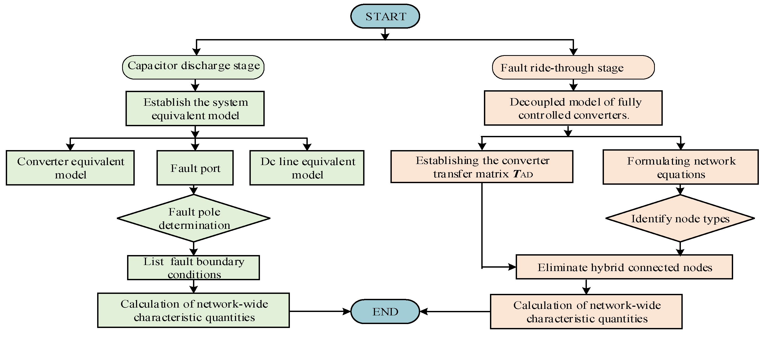
2.2. Short-Circuit Calculation Method During Capacitor Discharge Stage

When the AC system experiences a fault, the port established in each sequence network through the symmetrical component method is referred to as the fault port. Similarly, for a DC grid fault, the fault port of each mode domain through pole-mode transformation is referred to as the DC fault port (hereinafter referred to as the fault port).
Based on the analysis in Section 2.1, the entire flexible DC network can be approximated as a linear system during the initial fault stage. Thus, the superposition theorem can be applied to decompose it into the normal network and the fault network, allowing for separate solutions for each. Then the fault network can be further simplified to derive its fault port equivalent model, as shown in Figure 6. (For a horizontal fault, only F is an independent node).
The reference direction of the current is selected as the inflow fault port. According to Figure 6, various electrical quantities can be represented as Equation (5). The following electrical quantities are complex frequency domain parameters unless otherwise specified.
I a ( s ) = I F ( s ) ( F ) = I T ( s ) ( F ) ( s = 0 , 1 ) U a ( s ) = U a ( s ) ( 0 ) + U a ( s ) ( F ) = U a ( s ) ( 0 ) + U F ( s ) ( F ) U T ( s ) ( F )
where U a ( s ) and I a ( s ) are the fault port voltage and current, I F ( s ) ( F ) , I T ( s ) ( F ) , U F ( s ) ( F ) , and U T ( s ) ( F ) are the fault components of the fault port current and voltage, and U a ( s ) ( 0 ) is the normal component of the fault port voltage.
Based on the fault port model, a solution method for network-wide characteristic quantities is established in Equation (6).
U ( s ) = U ( s ) ( 0 ) + U ( s ) ( F ) = Z ( s ) I ( s ) ( 0 ) + Z ( s ) I ( s ) ( F )
where Z ( s ) is the impedance matrix of the nodes in each mode domain network, I ( s ) ( 0 ) and U ( s ) ( 0 ) are the normal component of the injected current and voltage at the nodes in each mode domain network, and I ( s ) ( F ) and U ( s ) ( F ) are the fault components of the injected current and voltage at the nodes in each mode domain network. The normal component is derived from the pre-fault power flow calculation, while the fault component only exists at the fault port nodes, with no fault current injected at the other nodes, as shown in Equation (7).
I ( s ) ( F ) = 0 I a ( s ) I a ( s ) 0 T F T
Furthermore, the port impedance Za(s) is usually defined as the equivalent impedance of each network viewed from the entire system through the fault port [26] and it is indicated in Equation (8):
Z a ( s ) = Z FF ( s ) + Z TT ( s ) 2 Z FT ( s )
Substituting the fault node current and fault port impedance from Equations (7) and (8) into Equation (6) yields the fault port equations for the 1-mode and 0-mode networks, respectively.
U a ( 1 ) = U a ( 1 ) ( 0 ) + U a ( 1 ) ( F ) = Z a ( 1 ) I ( 1 ) ( 0 ) + Z a ( 1 ) I a ( 1 ) U a ( 0 ) = U a ( 0 ) ( 0 ) + U a ( 0 ) ( F ) = Z a ( 0 ) I ( 0 ) ( 0 ) + Z a ( 0 ) I a ( 0 )  
In the absence of zero-mode voltage during normal network operation, Equation (9) can be reduced to a simpler form, as Equation (10).
U a ( 1 ) U a ( 0 ) = U a ( 1 ) ( 0 ) 0 + Z a ( 1 ) Z a ( 0 )   I a ( 1 ) I a ( 0 )
where the unknowns are fault port voltages and currents of 0-mode and 1-mode, totaling four in number. The two equations mentioned are not sufficient for a direct solution; thus, it is necessary to further incorporate corresponding boundary conditions, which are contingent upon the specific type of fault.
In the case of a pole-to-ground fault, both 0- and 1-mode components are present. Depending on the grounding pole, the fault can be categorized as a positive pole-to-ground short circuit or a negative pole-to-ground short circuit.
(1) For a positive pole-to-ground short circuit, the current reference direction is selected as flowing into the earth at the fault point. After the pole-mode transformation, the boundary conditions of the mode domain fault port are expressed in Equation (11).
I a ( 1 ) = I a ( 0 ) U a ( 1 ) ( F ) + U a ( 0 ) ( F ) = ( I a ( 1 ) + I a ( 0 ) ) R f 2 U dc
From Equation (10), it is evident that during a positive pole-to-ground short circuit, the fault components of the 0-mode current and 1-mode current at the fault point are equal. Thus, the fault network in the mode domain can be considered as connected in series, as shown in Figure 7a.
On this basis, the fault network can be further simplified to establish the series equivalent model of the fault port, as shown in Figure 7b.
According to the equivalent model described above, substituting the boundary conditions into the fault port allows for the determination of current, as shown in Equation (12).
I a ( 1 ) = I a ( 0 ) = 2 U dc Z a ( 1 ) + Z a ( 0 ) + 2 R f
(2) In the same way, Equation (13) presents the boundary conditions of the fault port in the case of a negative pole-to-ground fault.
I a ( 1 ) + I a ( 0 ) = 0 U a ( 0 ) ( F ) U a ( 1 ) ( F ) = ( I a ( 0 ) I a ( 1 ) ) R f 2 U dc
The analysis reveals that for a negative pole-to-ground short circuit, the fault components of the 0-mode and 1-mode currents at the fault point are equal in magnitude but opposite in direction. Therefore, the fault network can be represented as a parallel equivalent model, as shown in Figure 8a and Figure 8b which show the simplified parallel fault port model.
According to the principle of parallel circuit current division, the fault current of the fault port can be calculated separately, as shown in Equation (14).
I a ( 0 ) = 2 U dc Z a ( 1 ) + Z a ( 0 ) + 2 R f I a ( 1 ) = 2 U dc Z a ( 1 ) + Z a ( 0 ) + 2 R f
With the fault current established, it can be substituted into Equation (15) to calculate voltage and corresponding branch current at any node of the whole network during a fault. By performing the inverse pole-mode transformation, the voltage and current of the fault pole can ultimately be obtained, allowing for the determination of network-wide characteristic quantities.
U m ( 1 ) U m ( 0 ) = U m ( 1 ) ( 0 ) + Z mF ( 1 ) I a ( 1 ) Z mF ( 0 ) I a ( 0 )

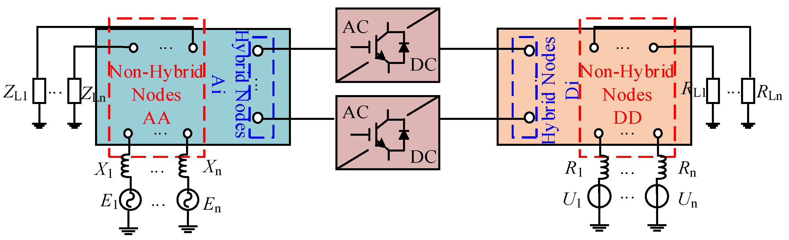
2.3. Equivalent Model During Fault Ride-Through Stage

In flexible DC distribution networks, the progression of a short-circuit fault begins with the capacitor discharge stage, characterized by the rapid discharge of the converter station’s equivalent capacitance to the fault location. Due to the low-damping nature of these networks, the short-circuit current can reach the converter blocking threshold within milliseconds, posing a significant risk of system-wide outages. Consequently, enhanced fault ride-through capabilities are now essential for converters to maintain system security and stability. Following a fault the collaborative operation of DC circuit breakers or self-clearing converters with protection mechanisms effectively suppresses the fault current, marking the transition from the capacitor discharge phase to the fault ride-through phase. Distinct from the characteristics of the capacitor-discharge stage, it involves strong coupling between the AC and DC sides during the fault ride-through stage, and the interaction among multiple converters cannot be adequately addressed using a fault port model. Therefore, the remodeling and analysis of the fault network are of paramount importance, especially in establishing a new equivalent converter model, which is essential for short-circuit calculations. In this section, a mathematical converter calculation model is derived based on the flexible DC grid and converter topology, combined with the converter control strategy and modulation methods.
According to [27], the fully controlled converter can be divided into an AC part and a DC part. The equivalent internal potentials of these two parts are connected through the modulation method used by the converter. Figure 9 shows the equivalent circuit of a fully controlled converter. In this model, UAi is the AC side output voltage of the ith converter, IAi is the AC side output current of the ith converter, XCi is the converter reactance of the ith converter, EAi is the AC side equivalent internal voltage of the ith converter, UDi is the DC side output voltage of the ith converter, IDi is the DC side output current of the ith converter, and EDi is the DC side equivalent internal voltage of the ith converter.
Generally, the fully controlled converter adopts double closed-loop control. The outer loop controls fixed DC voltage and fixed reactive power, while the inner loop controls the inner loop current, which effectively enables independent control of the output current on the dq-axis. At this point, the output current of the converter can be expressed as I ˙ Ai = I Adi + j I Aqi , where I Adi is the d-axis current at the AC side outlet of the ith inverter and I Aqi is the q-axis current.
From the equivalent circuit of a fully controlled converter in Figure 6, the AC side internal voltage during the fault ride-through stage can be calculated as shown in Equation (16).
E · Ai = U Ai + j X Ci ( I Adi + j I Aqi )
The fully controlled converter typically utilizes pulse width modulation [28]. On this basis, the relationship between the equivalent internal voltage on the AC side and the DC side is expressed in Equation (17).
E · Ai = E Di / 2 × M · Ai = U Di / 2 × M · Ai
where MAi is the power frequency quantity corresponding to the modulated signal. In addition, the fully controlled converter must satisfy the active power conservation constraint [29] on the AC and DC sides, as shown in Equation (18).
U Ai I Ai cos σ Ai + U Di I Di = 0
where σ A i is the phase angle of the output current on the AC side of the ith converter. Combining the above equations, the fault equivalent model of the fully controlled converter is presented in Equations (19) and (20).
U Di = 2 M Ai U Ai + 2 j X Ci M Ai ( I Adi + j I Aqi )
I Di = cos σ Ai 2 / M Ai + 2 j γ / M Ai ( I Adi + j I Aqi )
where the coefficient γ is a regulation factor determined by the AC voltage, the AC current, and the filter inductance, i.e., γ = X Ci I Ai / U Ai .
The nodes in a flexible DC distribution network can be classified into hybrid nodes and non-hybrid nodes according to whether there is a coupling relationship between the AC and DC sides of the converter, as shown in Figure 10.
AA is the AC non-hybrid node, DD is the DC non-hybrid node, and Ai and Di are AC/DC hybrid nodes. Following the fault equivalent network, the hybrid nodes are analyzed separately from the non-hybrid nodes. Then the voltage equations of both AC and DC side nodes can be established, respectively, in Equation (21).
U AA U Ai = Z AA Z A 1 Z A 2 Z Ai I AA I Ai U DD U Di = Z DD Z D 1 Z D 2 Z Di I DD I Di
where UDi and UDD are the voltage matrices of the DC side hybrid nodes and non-hybrid nodes, respectively, UAi and UAA are the voltage matrices of the AC side hybrid nodes and non-hybrid-connected node, and IDi and IDD are the current injection matrices from the AC side through the converter to the hybrid-connected node and non-hybrid-connected node. IAi and IAA are the injection current matrices from the AC side via the converter to the hybrid and non-hybrid nodes, respectively; ZDi and ZAi are the impedance matrices of the hybrid node. ZAA and ZDD are the node impedance matrices of the non-hybrid nodes. Finally, we define ZA1, ZA2, ZD1 and ZD2 as the mutual impedance matrices between the two nodes.

2.4. Short-Circuit Calculation Method During Fault Ride-Through Stage

During the fault ride-through stage, there is a strong coupling relationship between the electrical quantities on the AC and DC sides of the converter. And the solution of the fault node is constrained by the inherent characteristics of the converter. This section establishes the converter transfer matrix TAD to calculate network-wide characteristics quantities, as shown in Equation (21).
U Ai I Ai = T AD U Di I Di = T 11 T 12 T 21 T 22 U Di I Di
where T11 is the transfer matrix for node voltages, T22 is the transfer matrix for currents, and T12 and T21 are the transfer matrices between voltages and currents.
The fully controlled converter adheres to the modulation constraints for AC and DC voltages Equation (17) and the active power constraint Equation (18). In the event of a DC-side fault, the DC voltage is determined by the external fault, and the DC current is governed by the fault ride-through control based on that voltage. Thus, the expressions for AC-side voltage and current in the case of a pole-to-ground fault can be derived in Equation (23).
U Ai I Ai = M Ai 2 2 X Ci ( j γ ) M Ai cos σ Ai 0 3 ( 1 + j γ ) cos σ Ai M Ai e j ω t U Di I Di
Initially, the converter port transfer matrix is incorporated into Equation (21), enabling the elimination of hybrid nodes on the DC side and the consolidation of non-hybrid nodes, as demonstrated in the following equation.
U AA U DD = Z AA 0 0 Z DD I AA I DD + 0 Z A 1 Z D 1 T 21 Z D 1 T 22 U Ai I Ai
Subsequently, by leveraging Equation (22), the hybrid nodes on the AC side are systematically reorganized, establishing a clear relationship between their voltage and current and those of the non-hybrid nodes, as shown in Equation (25).
U Ai I Ai = = 1 Z Ai ( T 12 Z Di T 22 ) 1 ( T 11 Z Di T 21 ) 1 1 × Z A 2 0 0 ( T 12 Z Di T 22 ) 1 Z D 2 I AA I DD
Ultimately, the AC and DC node voltage equations are derived for different fault locations, facilitating the computation of network characteristic quantities, as demonstrated in Equation (26)
U AA U DD = ( T 11 + T 12 ) Z AA T 11 Z A 1 Z A 2 + Z DD T 12 Z A 1 Z A 2 Z Di T 21 Z Ai Z AA Z Di T 22 Z AA T 11 + T 12 + Z Di T 21 Z Ai + T 22 Z D 2 T 11 + T 12 + Z Di T 21 Z Ai + T 22 Z D 1 ( T 21 Z A 2 T 21 Z Ai Z AA Z A 1 1 T 22 Z AA Z A 1 1 ) + Z D 1 Z A 1 1 ( T 21 Z Ai + T 22 ) T 11 + T 12 + Z Di T 21 Z Ai + T 22 Z DD + Z D 1 Z D 2 ( T 21 Z Ai + T 22 ) Z A 1 ( T 11 + T 12 + Z Di T 21 Z Ai + T 22 ) I AA I DD
According to the superposition theorem, the characteristic quantity of a short-circuit fault can be decomposed into the normal component and the fault component. In the fault network, only the faulty node has an injection current. Suppose that an asymmetric short-circuit fault occurs at node k on the DC side, the resulting node voltage equations are represented in Equations (27) and (28).
Δ U A 1 Δ U AN A = Z A 1 D 1 Z A 1 Dk Z A 1 DN D Z AN A D 1 Z AN A Dk Z AN A DN D 0 I k 0
Δ U D 1 Δ U k Δ U D N D = Z DD 11 Z DD 1 k Z DD 1 N D Z DDk 1 Z DDkk Z DDkN D Z DDN D 1 Z DDN D k Z DDN D N D 0 I k 0
where ZAiDj is the DC–AC hybrid mutual impedance, ZDDii is the DC self-impedance, and ZDDij is the DC mutual impedance. ΔUAi is the fault component of AC node voltage and ΔUDi is the fault component of DC node voltage. Ik is the fault injection current, which is calculated in Equation (29):
I k = U k 0 Z DDkk + R k 1 Z DDkk + R k
where Rk is the fault resistance and U k 0 is the normal component of voltage at the fault point. Then substituting Ik into Equations (27) and (28) can yield the voltage at any node, as shown in Equation (30).
U A 1 = U A 1 0 + Δ U A 1 = U A 1 0 Z A 1 Dk 1 Z A 1 Dk I k U AN A = U AN A 0 + Δ U AN A = U AN A 0 Z AN A Dk 1 Z AN A Dk I k U D 1 = U D 1 0 + Δ U D 1 = U D 1 0 Z DD 1 f D I k 1 Z DD 1 k I k U Dk = U k 0 + Δ U k = R k I k U DN D = U DN D 0 + Δ U DN D = U DN D 0 Z DDN D k I k 1 Z DDN D k I k
Ultimately, Equation (31) presents the approach to branch currents resolution:
I i j = U i U j Z i j Δ U i Δ U j Z i j
The calculation flow during the entire asymmetric short-circuit fault is shown in Figure 11. During the capacitor discharge stage, the fault equivalent model of the system, encompassing converters and DC lines, is formulated. The fault boundary conditions are subsequently applied to the fault port equations to determine the network-wide characteristic quantities. In the fault ride-through stage, the converter undergoes AC/DC decoupling, and the resulting port transfer matrix is incorporated into the network equations. Following node type identification and hybrid node elimination, the network-wide characteristic quantities are accurately calculated.

3. Results and Discussion

In the model of a six-terminal ring flexible DC distribution network based on the PSCAD/EMTDC platform, as shown in Figure 1, the rated voltage of the DC line is ±10 kV, the impedance between node 1 and node 8 is 0.415+j0.004pu, and the impedance between 8 and 9 is 0.221+j0.191pu. The system consists of three AC nodes, numbered 1, 8, and 9, and six DC nodes, numbered 2–7. Among them, AC node 1 and DC node 2 are hybrid nodes connected by the fully controlled converter. Relevant system parameters are detailed in Table 1 and Table 2.
According to the system parameters, the equivalent model of the MMC can be calculated as Lm = 6.7 mH, Cm = 2.5 mF, and Rm = 0.0067 Ω.
The node admittance matrix can be determined by calculating the inverse matrix based on the system parameters. The impedance matrices for the AC and DC nodes are presented in Equations (32) and (33), respectively.
Z A C b u s = 2.778 2.778 2.778 2.778 2.363 + j 0.004 2.363 + j 0.004 2.778 2.363 + j 0.004 2.142 + j 0.195 1 8 9
Z D C b u s = 0.415 0.332 0.581 0.415 0.083 0.249 0.207 0.083 0.456 0.415 0.290 0.249 0.415 0.415 0.415 0.415 0.415 0.415 0.622 0.747 0.788 0.415 0.539 0.581 0.223 0.498 0.664 0.415 0.332 0.166 0.208 0.415 0.622 0.415 0.208 0.415 2 3 4 5 6 7

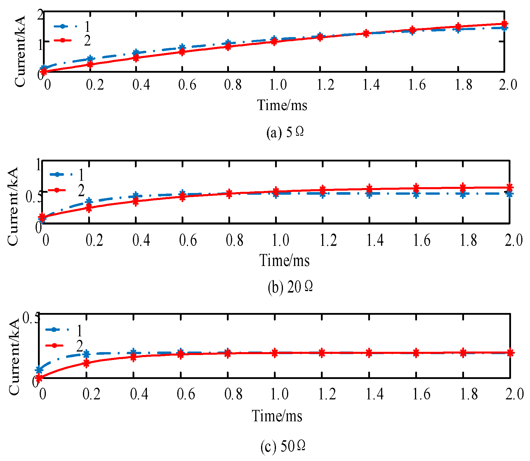
3.1. Capacitor Discharge Stage

Given that the response time of the converter control in practical engineering typically falls within 2 ms, the simulation focuses on verifying the accuracy of the proposed short-circuit calculation method within this timeframe. In the subsequent figure, Curve 1 represents the simulation result, while Curve 2 depicts the calculation results. Figure 12 shows the short-circuit current response when a positive pole-to-ground fault occurs at point f1 (with different fault resistances).
The analysis indicates that during the capacitive discharge stage, the short-circuit current obtained from the fault port model aligns closely with the simulation result in terms of trend with minimal numerical errors. Although, the calculated rate of change in current is slightly delayed compared to the simulation curve due to the simplification of the equivalent fault network, which considers high-frequency impedance characteristics while neglecting the capacitive shunt effect—both results converge around 0.4 ms. In practical systems, this current delay is negligible.
For a negative pole-to-ground fault, the short-circuit current calculated using the parallel fault model also demonstrates a high correlation with the simulation results shown in Figure 13. Comparing Figure 12 and Figure 13, it is evident that in a symmetric bipolar DC system, the magnitude of the negative pole-to-ground fault current equals that of the positive pole-to-ground fault current, while their directions are opposite, which is consistent with the relationship between the modulus current derived in Section 2. This dual-domain perspective enables innovative protection strategies by extracting fault quantities from both pole and modal domains, thereby enriching the toolbox for protection scheme design.

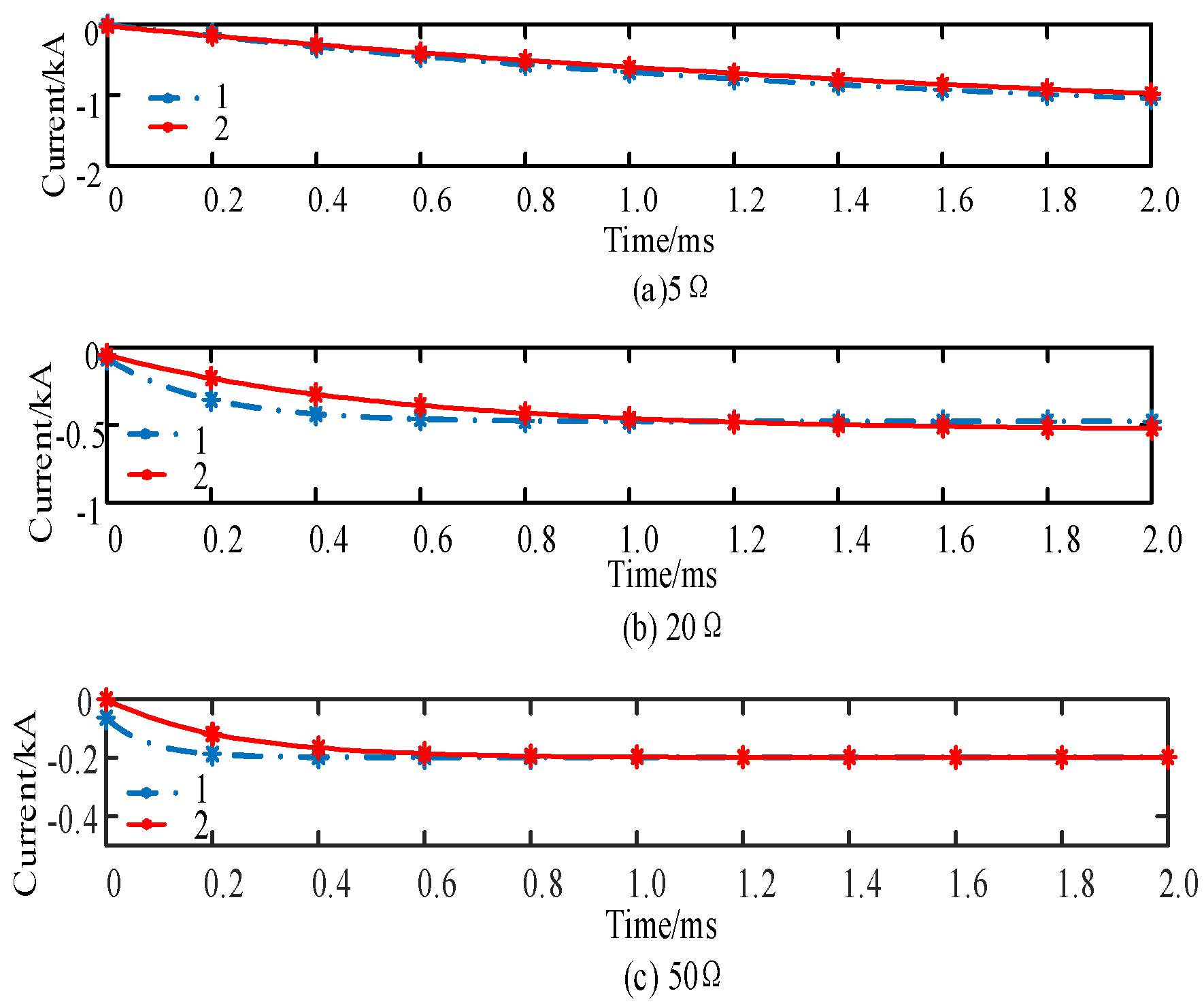
3.2. Fault Ride-Through Stage

When a pole-to-ground short-circuit fault occurs at the system f1 point, the converter port transfer matrix at this time can be derived from Equation (25), which is 0.55 0.006 + j 0.293 0 2.049 j 1.800 . After eliminating hybrid nodes, the impedance matrix of the grid nodes can be obtained.
3.674 + j 0.121 2.674 + j 0.121 0.174 j 0.031 0.412 + j 0.071 0.275 j 0.044 0.164 j 0.110 0.231 + j 0.131 1.450 + j 0.132 0.251 + j 0.220 0.275 j 0.101 0.815 + j 0.415 0.201 j 0.514 0.421 j 0.118 0.312 + j 0.312 0.519 + j 0.417 0.069 + j 0.441 0.162 j 0.041 0.074 + j 0.124 0.152 j 0.113 0.041 + j 0.242 0.402 + j 0.503 0.180 j 0.597 0.814 j 0.509 0.592 + j 0.125 0.421 j 0.122 0.112 + j 0.706 0.105 + j 0.012 0.007 j 0.504 0.107 + j 0.400 0.857 + j 0.441 0.133 j 0.047 0.254 + j 0.572 0.414 j 0.219 0.357 j 0.414 0.247 + j 0.124 0.631 + j 0.521 0.637 + j 0.511 0.444 j 0.002 0.441 + j 0.404 0.126 j 0.123 0.125 j 0.048 0.013 + j 0.047 0.214 j 0.412 0.412 j 0.712 0.101 + j 0.013 0.004 j 0.006 0.041 + j 0.001 0.071 + j 0.412 0.141 j 0.044 8 9 3 4 5 6 7
According to Equations (27) and (28), the currents in each branch are obtained and compared with the steady-state currents obtained from the simulation, as shown in Figure 14. Then the current calculation errors in each branch can be derived, as shown in Table 3.
The results indicate that the closer the distance to the short-circuit point, the smaller the error. Conversely, as the distance escalates, the error correspondingly magnifies, with the maximum relative error remaining below 5%. Compared with the traditional calculation method, the proposed method demonstrates greater accuracy, effectively calculating the network-wide characteristics during asymmetrical short-circuit faults in the flexible DC distribution network with fully controlled converters.

3.3. Comparative Analysis with Existing Methods

To further demonstrate the efficacy of the proposed method, Figure 15 shows the calculation results under a positive pole-to-ground fault condition (transition resistance of 5 Ω). The results are compared to existing methods: Curve 1 (simulation), Curve 2 (proposed method), Curve 3 (Reference [14]), and Curve 4 (Reference [23]).
(1) In contrast to the open-loop simplification required by Reference [14], the proposed method achieves the precise computation of network-wide characteristic quantities without such limitations. While Reference [14] reduces multi-terminal loop networks to chain branches and represents converter stations as parallel two-port networks to preserve discharge paths and lower computational complexity, it fails to capture the mutual coupling among discharge paths. The proposed method circumvents this by directly formulating a DC fault port model, ensuring higher accuracy through solving the network equation, as shown in Figure 15.
(2) Compared with Reference [23], which neglects resistance and healthy pole effects, the proposed method delivers superior computational accuracy. Reference [23] simplifies the system into a purely inductive network by leveraging high-frequency impedance characteristics, streamlining the inverse Laplace transform into linear equations for enhanced efficiency. However, this simplification disregards resistance and healthy pole impacts and omits network-wide characteristic calculation. The proposed method advances this by modeling the fault network as a resistive–inductive system, employing the pole-mode transformation for line decoupling, and constructing a composite modal fault port model that achieves higher accuracy in network-wide characteristic calculation, as depicted in Figure 15.

4. Conclusions

The evolution of flexible DC grids towards multi-terminal and multi-mesh configurations has rendered their fault characteristics increasingly complex and stage-dependent, posing substantial challenges for precise short-circuit current calculation. In response, this paper proposes a novel method for short-circuit calculation in flexible DC grids, covering the entire fault ride-through process and incorporating network-wide characteristic quantities.
Initially, stage-specific equivalent models of the fault network are established. During the capacitor discharge stage, an equivalent model with a DC fault port is formulated, and boundary conditions corresponding to various fault types are derived and solved through the fault port equations. Subsequently, in the fault ride-through stage, the converter port transfer matrix is developed based on the AC/DC side constraints of the converter, enabling the computation of network-wide characteristic quantities by integrating the matrix into the network node equations. The main conclusions are as follows.
The proposed method yields results that closely match the simulation data across fault resistances of 5 Ω, 20 Ω, and 50 Ω, exhibiting robustness against resistance variations. Errors decrease significantly near the fault location and increase with distance, but the maximum relative error remains below 5%, validating the method’s accuracy and reliability. The proposed method ensures the accurate determination of network-wide characteristic quantities during all phases of fault progression. It can be directly applied to the design and optimization of protection schemes, such as the coordination of DC circuit breakers and fault current limiters. Moreover, the current calculations do not account for energy storage systems or control system dynamics, potentially leading to some degree of error in the results. Future research can focus on extending the proposed method to multi-terminal DC grids with the utilization of energy storage systems, and the influence of converter control strategies could be investigated to further improve fault ride-through capabilities and overall system resilience.

Author Contributions

Writing—original draft preparation, methodology, and formal analysis, X.L.; writing—review and editing, Q.L.; software and validation, H.L.; data curation, X.Z.; project administration and investigation, Z.D. All authors have read and agreed to the published version of the manuscript.

Funding

This research was funded by the Guizhou Power Grid Co., Ltd. Technology Project (Grant No. GZKJXM20222149).

Data Availability Statement

All data are contained within this article.

Conflicts of Interest

Authors Xinhao Li and Qianmin Li were employed by the company, China Guizhou Power Grid Co., Ltd. The remaining authors declare that the research was conducted in the absence of any commercial or financial relationships that could be construed as a potential conflict of interest.

Abbreviations

The following abbreviations are used in this manuscript:
MMCModular multilevel converter
DCTDirect circuit transformer
VSCVoltage source converter
LCCLine-commutated converter

References

  1. He, J.; Liu, B.; Duan, S. A selective protection strategy for inverter-based power grid. High Volt. Eng. 2022, 48, 2357–2365. [Google Scholar]
  2. Zeng, R.; Zhao, Y.; Zhao, B.; Zhong, Q.; Tong, Y. A prospective look on research and application of DC power distribution technology. Proc. CSEE 2018, 38, 6791–6801. [Google Scholar]
  3. Zhou, F.; Kawaguchi, T.; Hashimoto, S. Multi-Terminal DC Transformer for Renewable Energy Cluster Grid Connection. Energies 2024, 17, 5152. [Google Scholar] [CrossRef]
  4. Lu, S.; Liu, H. Study on Investment Evaluation Index System of Pilot Project of Incremental Power Distribution Service Reform. Power Syst. Big Data 2022, 12, 77–84. [Google Scholar]
  5. Perera, C.; Salmon, J.; Kish, G.J. Multiport Converter with Independent Control of AC and DC Power Flows for Bipolar DC Distribution. IEEE Trans. Power Electron. 2021, 36, 3473–3485. [Google Scholar] [CrossRef]
  6. Kim, Y.H.; You, H.S.; Kim, S.J.; Choi, S.M.; Rho, D.S. An Implementation of Intelligent Fault Isolation Device for LVDC Distribution System Considering Slope Characteristics of Fault Current. Electronics 2025, 14, 171. [Google Scholar] [CrossRef]
  7. Javed, W.; Chen, D.; Farrag, M.E.; Xu, Y. System configuration, fault detection, location, isolation and restoration: A review on LVDC microgrid protections. Energies 2019, 12, 1001. [Google Scholar] [CrossRef]
  8. Lai, D.; Luo, W.; Huang, J. Adaptive Control of Hybrid Energy Storage Power for Multiple Microgrids Based on Edge Computing. Power Syst. Big Data 2023, 4, 28–35. [Google Scholar]
  9. Xu, J.; Zhao, X.; Jing, H.; Liang, J.; Zhao, C. DC Fault Current Clearance at the Source Side of HVDC Grid Using Hybrid MMC. IEEE Trans. Power Deliv. 2020, 35, 140–149. [Google Scholar] [CrossRef]
  10. Wang, C.; Tao, J.; Wang, Y.; Tan, K.; Xu, T. Research on topology and fault ride-through strategy of hybrid arm multiplexing MMC composed of HBSMs and FBSMs. Proc. CSEE 2022, 42, 8297–8309. [Google Scholar]
  11. Cwikowski, O.; Wickramasinghe, H.R.; Konstantinou, G.; Pou, J.; Barnes, M.; Shuttleworth, R. Modular Multilevel Converter DC Fault Protection. IEEE Trans. Power Deliv. 2018, 33, 291–300. [Google Scholar] [CrossRef]
  12. Li, H.; Dai, Z.; Shi, X.; Yang, M. Approximate Calculation Method of Short-Circuit Current of Multi-Terminal Hybrid DC Transmission System Considering Control Strategy. Trans. China Electrotech. Soc. 2024, 39, 2810–2824. [Google Scholar]
  13. Tang, L.; Dong, X. An approximate method for the calculation of transmission line fault current in MMC-HVDC grid. Proc. CSEE 2019, 39, 490–498. [Google Scholar]
  14. Xin, Y.; Luo, X.; Wang, T.; Wang, Y.; Wang, W. Simplified calculation method of fault current in different topological structures of DC grid considering the influence of transition resistance. Power Syst. Technol. 2023, 47, 804–817. [Google Scholar]
  15. Wang, Z.; Hao, L.; Wang, L.; He, J.; Chen, Z. Calculation method of nonmetallic short circuit fault current in DC side of MMC-HVDC system. Electr. Power Autom. Equip. 2024, 44, 187–194. [Google Scholar]
  16. Hao, L.; Li, W.; Wang, Z.; Gu, Y.; Wang, G. Practical calculation for bipolar short-circuit fault curren of transmission line in MMC-HVDC grid. Autom. Electr. Power Syst. 2020, 44, 68–76. [Google Scholar]
  17. Wang, Z.; Hao, L.; Wang, Z. Short-Circuit Current Calculation of Flexible Direct Current Transmission Lines Considering Line Distribution Parameters. Energies 2024, 17, 3800. [Google Scholar] [CrossRef]
  18. Liao, Y.; Jin, L.; You, J.; Xu, Z.; Liu, K.; Zhang, H.; Shen, Z.; Deng, F. A Novel Voltage Sensorless Estimation Method for Modular Multilevel Converters with a Model Predictive Control Strategy. Energies 2024, 17, 61. [Google Scholar] [CrossRef]
  19. Debnath, S.; Qin, J.; Bahrani, B.; Saeedifard, M.; Barbosa, P. Operation control and applications of the modular multilevel converter: A review. IEEE Trans. Power Electron. 2015, 30, 37–53. [Google Scholar] [CrossRef]
  20. Li, J.; Zhang, Z.; Li, Z.; Babayomi, O. Predictive Control of Modular Multilevel Converters: Adaptive Hybrid Framework for Circulating Current and Capacitor Voltage Fluctuation Suppression. Energies 2023, 16, 5772. [Google Scholar] [CrossRef]
  21. Torwelle, P.; Bertinato, A.; Raison, B.; Le, T.; Petit, M. Fault current calculation in MTDC grids considering MMC blocking. Electr. Power Syst. Res. 2022, 207, 1–12. [Google Scholar] [CrossRef]
  22. Song, J.; Cheah-Mane, M.; Prieto-Araujo, E.; Amorós, J.; Gomis-Bellmunt, O. Grid Equivalent Representation of Power Systems With Penetration of Power Electronics. IEEE Trans. Power Deliv. 2023, 38, 2742–2756. [Google Scholar] [CrossRef]
  23. Deng, W.; Liu, Q.; Zhang, Y.; Liu, T.; Li, B. Short circuit current calculation method and grounding strategy of pole-to-ground fault in zhangbei flexible DC power grid. High Volt. Eng. 2022, 48, 4050–4059. [Google Scholar]
  24. Dai, Z.; Liu, X.; Liu, Z.; Li, Y.; Chen, X. Pilot Protection Scheme for Flexible DC Distribution Grids Based on Superimposed Current. High Volt. Eng. 2021, 47, 1684–1693. [Google Scholar]
  25. Ye, H.; Gao, S.; Li, G.; Liu, Y. Efficient Estimation and Characteristic Analysis of Short-Circuit Currents for MMC-MTDC Grids. IEEE Trans. Ind. Electron. 2020, 68, 258–269. [Google Scholar] [CrossRef]
  26. Liu, W.; Huang, S.; Xu, Y. Fault Analysis of Power System, 3rd ed.; China Electric Power Press: Beijing, China, 2010. [Google Scholar]
  27. Shi, X.; Wang, Z.; Liu, B.; Li, Y.; Tolbert, L.; Wang, F. DC impedance modelling of a MMC-HVDC system for DC voltage ripple prediction under a single-line-to-ground fault. In Proceedings of the 2014 IEEE Energy Conversion Congress and Exposition (ECCE), Pittsburgh, PA, USA, 14–18 September 2014. [Google Scholar]
  28. Chen, L.; Xu, F.; Wei, X.; Tang, G.; Cui, X. A Review on Large Capacity Controllable Switching Current Source Converter Research. Electr. Power. 2021, 54, 25–36. [Google Scholar]
  29. Ding, Y.; Mao, M. Comparison and analysis of CPT-and IRPT-based current decomposition in multi-scenario. Electr. Power Autom. Equip. 2023, 43, 166–173. [Google Scholar]
Figure 1. Topology of flexible DC distribution grid.
Electronics 14 01120 g001
Figure 2. Equivalent models of VSCs and DCTs in capacitor discharge stage.
Electronics 14 01120 g002
Figure 3. Basic topology structure of MMC.
Electronics 14 01120 g003
Figure 4. Equivalent model of MMC in capacitor discharge stage. (a) Three-phase equivalent model of MMC. (b) Simplified model.
Electronics 14 01120 g004
Figure 5. Equivalent model of six-terminal ring flexible DC distribution network.
Electronics 14 01120 g005
Figure 6. DC fault port.
Electronics 14 01120 g006
Figure 7. Equivalent model of positive pole-to-ground fault.
Electronics 14 01120 g007
Figure 8. Equivalent model of negative pole-to-ground fault.
Electronics 14 01120 g008
Figure 9. The equivalent circuit of a full-bridge converter under fault conditions.
Electronics 14 01120 g009
Figure 10. Equivalent model during fault ride-through stage.
Electronics 14 01120 g010
Figure 11. Calculation flow in whole process of asymmetric short-circuit fault.
Electronics 14 01120 g011
Figure 12. Short circuit of positive electrode to ground under different fault resistances.
Electronics 14 01120 g012
Figure 13. Short circuit of negative electrode to ground under different fault resistances.
Electronics 14 01120 g013
Figure 14. Comparison of currents in each branch of pole-to-ground fault and simulation results.
Electronics 14 01120 g014
Figure 15. Comparison of calculation results from different methods.
Electronics 14 01120 g015
Table 1. Parameters of converters.
Converter StationSystem ParametersValues
MMC converter
station
Number of submodules on the bridge arm24
Submodule capacitance/μF10,000
Bridge arm inductance/H0.01
Smoothing reactor/mH5
IGBT on-resistance/Ω0.01
VSC converter
station
DC-side capacitance/μF4000
Flat wave reactor/mH30
IGBT on-resistance/Ω0.005
DCT converter
station
Low-voltage side capacitance/μF4000
High-voltage side capacitance/F0.1
IGBT on-resistance/Ω0.01
Table 2. Dc system parameters.
System ParametersValues
DC voltage level/kV±10
Current-limiting reactor/mH2
Line inductance per unit length (mH/km)0.78
Line resistance per unit length (Ω/km)0.083
Line mutual inductance per unit length (mH/km)0.1
Line 1, 2, 4, 5 length/km5
Line 3, 6 length/km15
Table 3. Simulation and calculation error of pole-to-ground fault.
BranchNode 3–4Node 4–5Node 5–6Node 6–7Node 8–9
error0.05%−1.97%3.56%−0.20%0.15%
Disclaimer/Publisher’s Note: The statements, opinions and data contained in all publications are solely those of the individual author(s) and contributor(s) and not of MDPI and/or the editor(s). MDPI and/or the editor(s) disclaim responsibility for any injury to people or property resulting from any ideas, methods, instructions or products referred to in the content.

