Article

Single Phase Induction Motor Driver for Water Pumping Powered by Photovoltaic System

by
Syed Faizan Ali Bukhari
1,
Hakan Kahveci
1 and
Mustafa Ergin Şahin
2,*
1
Department of Electrical and Electronics Engineering, Karadeniz Technical University, Trabzon 61080, Türkiye
2
Department of Electrical and Electronics Engineering, Recep Tayyip Erdoğan University, Rize 53100, Türkiye
*
Author to whom correspondence should be addressed.
Electronics 2025, 14(6), 1189; https://doi.org/10.3390/electronics14061189
Submission received: 5 February 2025 / Revised: 10 March 2025 / Accepted: 14 March 2025 / Published: 18 March 2025
(This article belongs to the Special Issue Power Electronics and Renewable Energy System)

Abstract

:
Photovoltaic energy is increasingly used in irrigation processes, particularly in arid regions, to pump water from rivers to fields. Rising oil prices, global warming, and the limited availability of fossil fuels have increased the need for alternative energy sources. This study focuses on the design and implementation of a transformerless single-phase photovoltaic system that powers a single-phase induction motor to drive a centrifugal water pump. The methodology aims to achieve the best system performance. A DC–DC boost converter maximizes the output voltage by utilizing maximum power point tracking (MPPT) and extracting the maximum power from the photovoltaic (PV) array. A bidirectional buck-boost converter charges the battery from the DC bus and discharges the battery voltage to the DC bus for loads. The DC voltage is then converted to AC output voltage using a single-phase inverter, which supplies power to the single-phase induction motor driver (IMD). The voltage/frequency (V/f) scaler control is used for a single-phase induction motor. The system employs scalar motor control to achieve the maximum motor speed required to operate the centrifugal water pump efficiently. All results and simulations are carried out in MATLAB/Simulink R2019a version and are compared for different motor and PV parameters numerically.

1. Introduction

Renewable energy sources are used for generating energy, more specifically electricity, that can be used for energy conversion. Solar energy is the most economical, efficient, and easily traced energy source compared with other renewable energy sources. Photovoltaic energy is widely used in homes, industries, remote areas, hospitals, agricultural purposes, parks, and public places. A standalone system being used in recent times is photovoltaic energy being used in the irrigation process for pumping water from the river to fields, mostly in arid regions where rainfall is very low. When the supply of grid-connected electricity is insufficient and watering is necessary for crops, it needs to obtain the water through any source possible [1].
A closed-loop space vector pulse width modulation (SVPWM)-based voltage/frequency (V/f) scalar control is studied in a paper. Independently, two single-phase induction motors (SPIM) with different speeds fed by a three-leg voltage source inverter (VSI) are implemented [2]. For photovoltaic power control, MPPT is generally used with DC-to-DC converters and advanced controllers [3,4]. In a study, an inverter-fed induction motor driver (IMD) for a water-pumping system is applied. Vector-controlled IMD is implemented to increase efficiency and decrease losses, and a minimization technique is proposed [5]. Control of the induction machine water pumping system is applied with the incremental conductance MPPT algorithm implemented for controlling the DC–DC converter, and V/f-based solar photovoltaic water pumping is used for controlling the VSI [6,7].
In the past decades, a large number of researchers have given the theory about the standalone PV systems that were used to operate three-phase induction motors as well as single-phase induction motors for low voltage operations, for example, modeling and simulation of the bidirectional buck-boost converter for the electrical vehicle applications [8]. The permanent magnet brushless DC motor was operated with the help of a DC–DC Cuk converter as well as three-phase inverters to control the motor speed as well as the charging and discharging of the battery for the required backup [9].
As far as the working mechanism and functionality of PV cells are concerned, it is found that advanced technology can convert sunlight into DC power [10]. Since the intensity of sunlight changes daily, the impact of Rsh (shunt resistance) at low sunlight intensity becomes extremely crucial. Thereby, it can be contended that in the cloudy data, the photovoltaic cells hold a greater value of their original power as compared with the one that has a low Rsh. The research work also adheres to these findings and has inspected the performance and efficiency as well as the development aspects of solar power systems [11,12].
It is possible to find some studies related to solar water pumping systems in the literature. Solar photovoltaic water pumping (SPVWP) is a cost-effective application in remote locations in developed countries, but drinking water is the number one priority for most of the population. SPVWP has not achieved great success yet. Even though a lot of challenges are associated with the SPVWP, especially in operation and maintenance. A study discusses some policies to make the SPVWP system an appropriate technology for the respective application region [13].
A study investigates some of the issues involved in solar water pumping projects, describes the positive and negative effects that they can have on the community, and, in proposing an entirely new type of pump, considers what steps could be taken to ensure future sustainability [14]. Photovoltaic water pumping (PVWP) systems can meet a wide range of needs and are relatively simple, reliable, cost-competitive, and low maintenance. A typical system configuration includes a PV array, pump, controller, inverter, and overcurrent protection [15,16].
Sandia National Laboratories (SNL) and the Southwest Technology Development Institute at New Mexico State University have been working in Mexico with a variety of program partners in developing sustainable markets for PV water pumping systems through the implementation of pilot projects. The program is sponsored by the US Department of Energy and the US Agency for International Development. In the area of water pumping, the tremendous rural demand for water represents a potential renewable market of over $500 million in Mexico. Through the SNL program, more than 130 photovoltaic water pumping projects have been installed in eight Mexican states, most in partnership with the Mexican Trust for Shared Risk or the Chihuahua Renewable Energy Working Group [17].
The PV-powered irrigation systems can be evaluated as on-grid and off-grid systems related to energy storage systems and power electronic topologies. If the PV systems include battery storage, they can be used at night or when electricity is cut and can be off-grid systems independent of the grid in rural farms or islands [18]. Moreover, using a hybrid energy storage system can increase the performance of the system and increase the storage energy with supercapacitors or any other alternating storage system [19]. The bidirectional converters play a key role in such a system for two-way energy flow from PV to battery and from battery to PV as a charger and discharger. Such a novel study is not used frequently in the literature related to advances and new technology [20].
This research aims to study the performance of a solar water pumping system using a single-phase induction machine with voltage/frequency (V/f) scaler control and to find its best appropriate configuration. In this study, the main purpose of finding the best configuration properties of a water pumping system is to make it useful for solar power irrigation systems. The available size of the PV array and the intensity of the solar energy are the key factors in determining the flow rate of the water pumped. The designed solar water pump system single-line diagram and its working principle are given in Figure 1.
There are five important points that should be considered while the whole process is designed in literature and our designed system [21]:
  • Available solar energy for the given site.
  • The volume of water needed for the irrigation process.
  • The given period depends upon the climate changes.
  • The quality and quantity of the water.
  • The reliability of the proposed topology and the system dynamics.
A solar irrigation system, which will be the basis for precise agricultural practices, has been proposed in this study. The amount of water to be pumped according to the soil moisture condition can be adjusted with this system. The system will be independent of the grid. It is in a hybrid structure consisting of PV panels and a battery group. The design of the control system that ensures the photovoltaic system, through maximum power point tracking, maintains the constant DC bus voltage of the battery pack while managing the charging and discharging system and operating the single-phase induction motor at the desired speed is discussed. The adequacy of the single-phase induction motor for the irrigation system has been evaluated. The water pump was driven by a single-phase induction motor in the proposed hybrid system. Motor speed control was conducted with voltage/frequency (V/f) closed-loop scalar control. The unipolar sine pulse width modulation (SPWM) technique has been used for the switching signals of the single-phase inverter, and a bidirectional DC–DC converter has been used to charge or discharge the battery group. The detailed simulation and numerical results are given in a comparable form for different parameters to verify this designed model system.

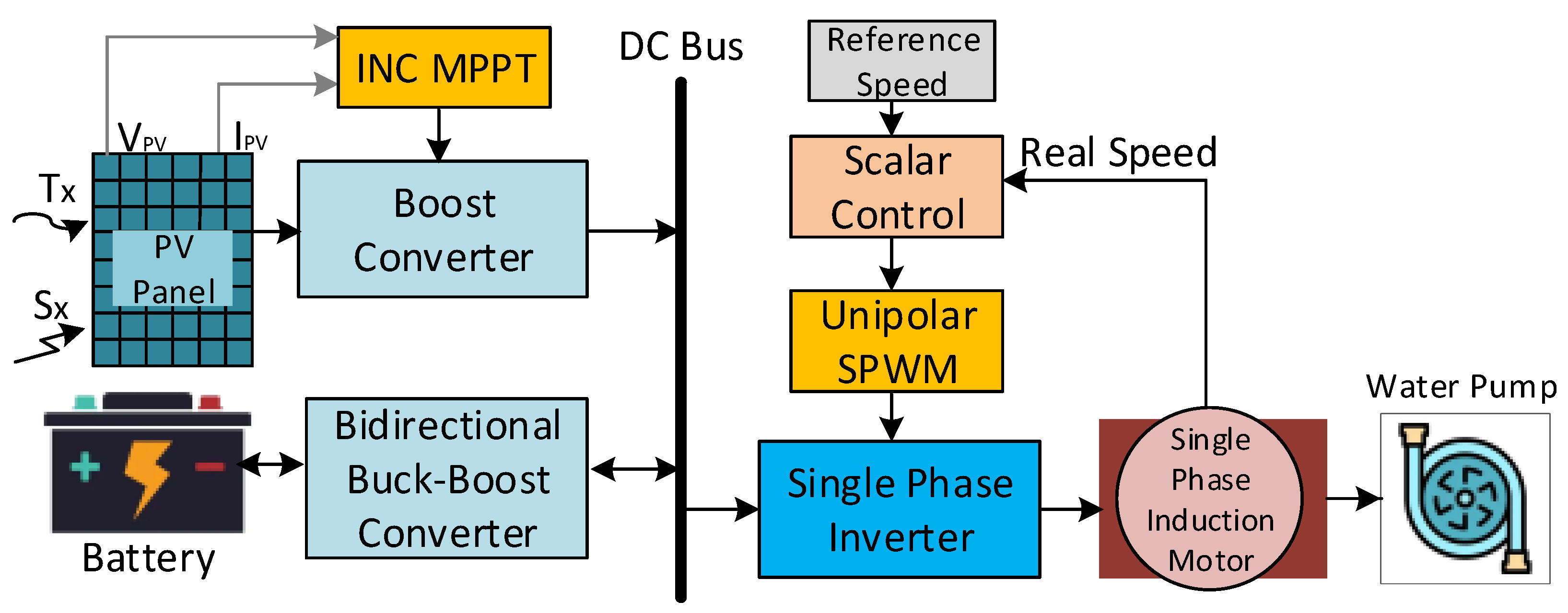
2. The Components of the Designed System

The designed PV-powered water pumping system with a converter is seen in Figure 2. The DC–DC boost converter is used to maximize the output voltage, which was conducted by using maximum power point tracking (MPPT) and extracting the maximum power through the photovoltaic (PV) array. The bidirectional buck-boost converter is used to charge and discharge the battery. The DC voltage is then converted to AC output by using a single-phase inverter, which gives the AC output to the single-phase induction motor driver. The system uses scalar control of the motor to run the centrifugal water pump. The designed basic system model to obtain the results is given in Figure 2.

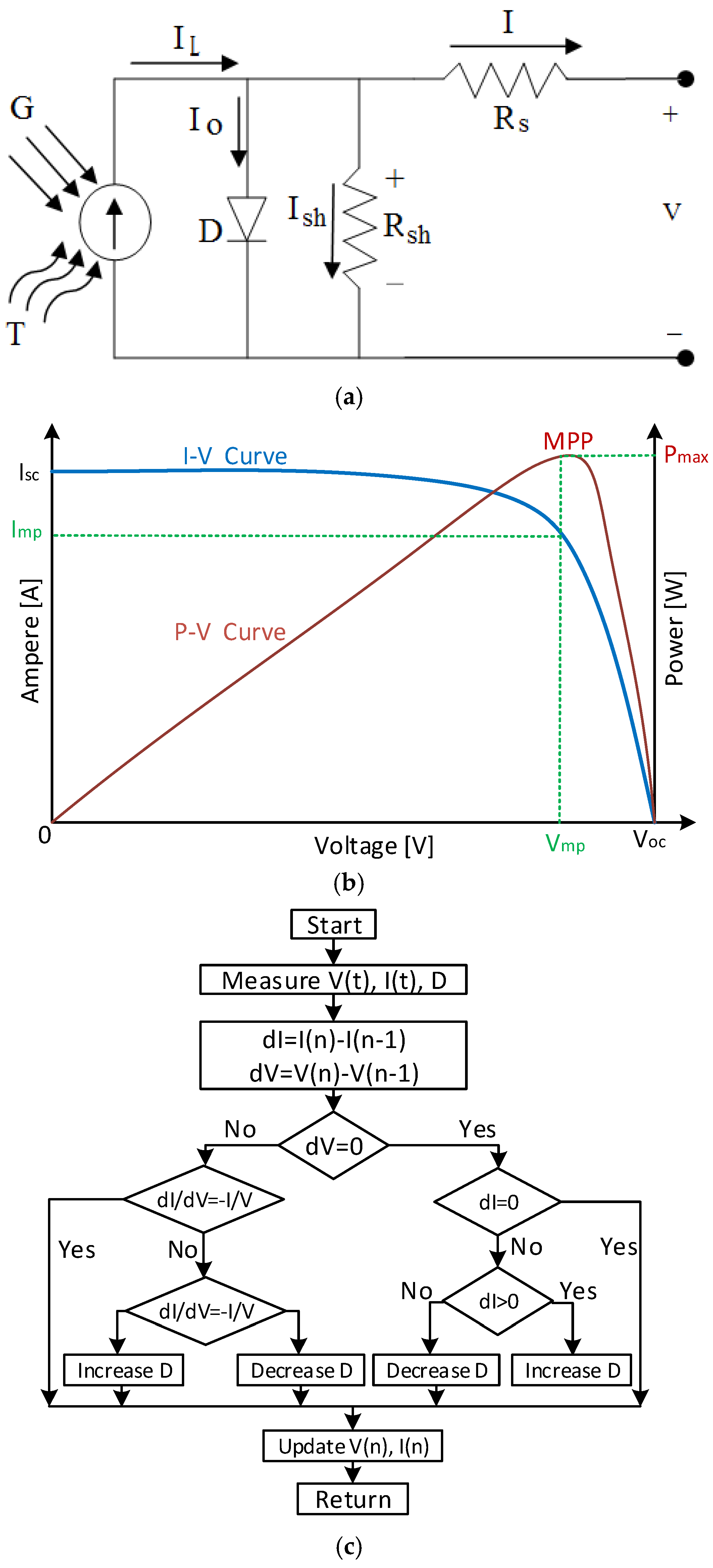
2.1. Photovoltaic Arrays

A photovoltaic array is a combination of several cells arranged in series and parallel connection. When they are connected in parallel, the produced current is increased, and when they are connected in series, the produced voltage is increased [22]. The PV cell can be substituted by the equivalent electric circuit that is comprised of a diode, series resistor, shunt resistor, as well as a power supply mechanism as seen in Figure 3a. When a resistive load is connected to the PV cell, then cells produce power as well as a crossing point volt-ampere characteristic. The I–V and P–V characteristics are shown in Figure 3b [16,23].
The emergence of the latest power control mechanism, commonly referred to as maximum power point tracking (MPPT) algorithms, has resulted in increasing the operational efficiency of solar modules. Several techniques are being used for tracking maximum power. These include fuzzy logic, neural networks, fractional open circuit voltage, fractional short circuit current, incremental conductance method, and hill-climbing method (perturb and observe). Amid all the traditional approaches presented in the previous literature, perturb and observe (P–O), as well as INC or IC (incremental conductance), has widely been used for commercial applications. The present study has made use of the INC MPPT algorithm, as seen in Figure 3c [24].

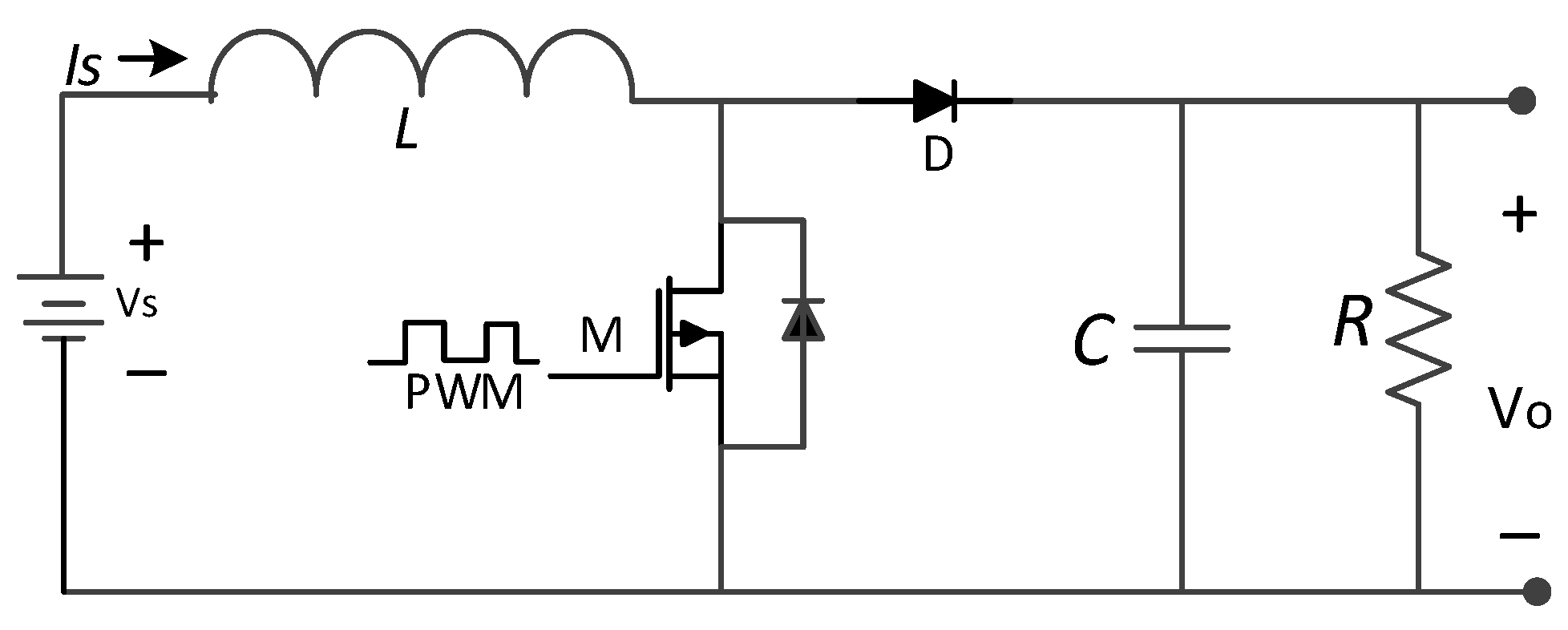
2.2. Boost Converter

The boost converter, which always gives the increased output for the given input voltage, is given in Figure 4. The gate signal is continuously switching the MOSFET using the generated PWM signal. The signal’s duty cycle determines the switching process of the MOSFET for voltage control purposes and to find the MPP of the photovoltaic array. To give the proper duty cycle, an MPPT system is used to find out the exact point where the system can operate. There are several MPPT methods for this, but the most commonly used method is P–O [23,26].

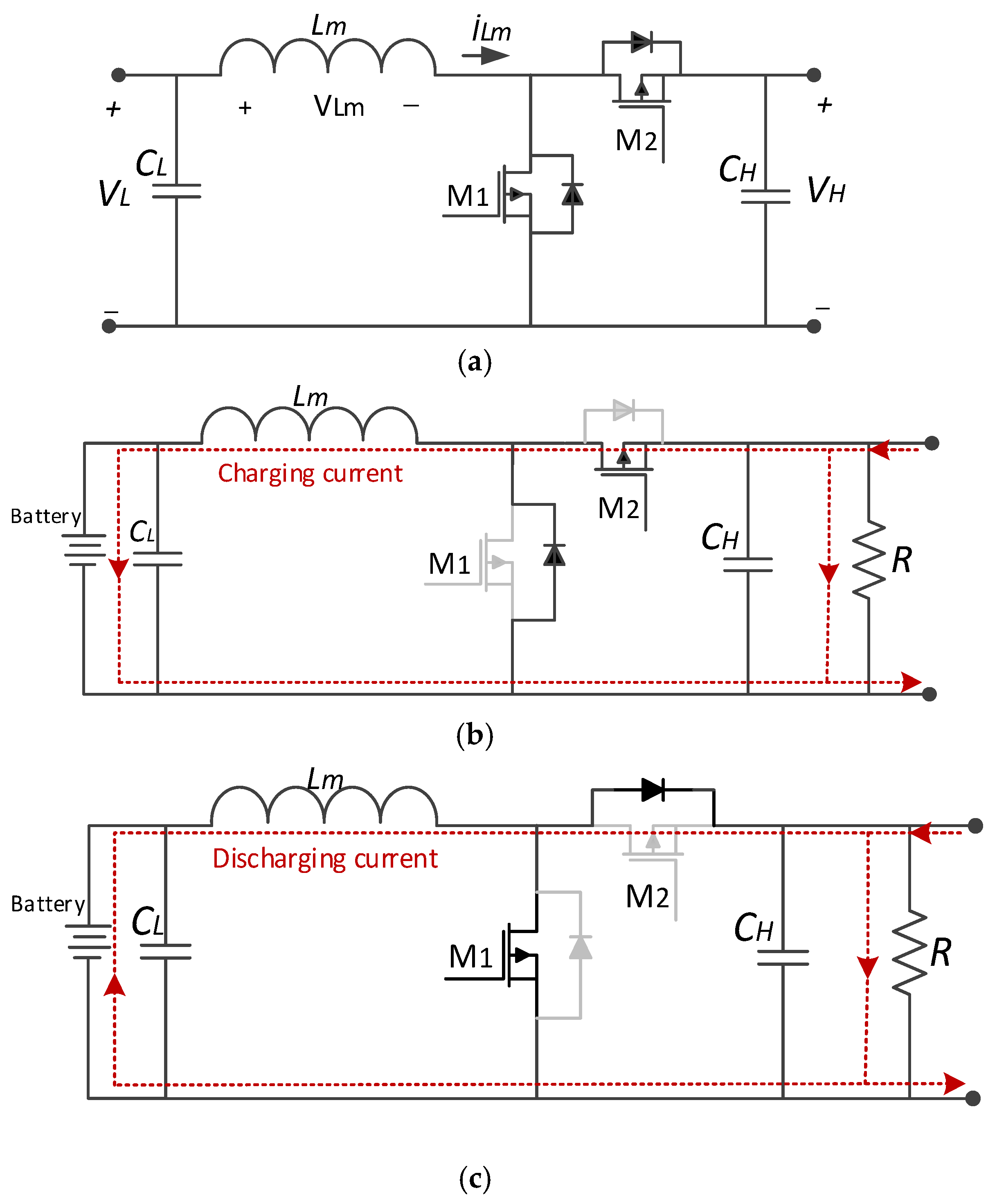
2.3. Bidirectional Buck-Boost Converter

A bidirectional DC–DC converter is a circuit where current flows in two directions, meaning that the bidirectional converter can energize the load, and the load side can also send the power back to the source. These properties of the converter made this converter suitable to charge and discharge the energy storage batteries from the DC bus, such as a PV-powered system to be used continuously. A bidirectional DC-to-DC buck-boost converter circuit where the current can flow in two directions is shown in Figure 5a. The operating modes of the bidirectional DC converter are shown in Figure 5b,c. There are two operating modes: the first one shows the charging, and the second one shows the discharging mode of the DC-to-DC converters [24,25,26].
The relationship between high side and low side voltage is shown in Equation (1).
V H = 1 1 D V L
For the inductance current under the continuous current mode (CCM), the inductance minimum value is defined with Equation (2).
L m , min D ( 1 D ) 2 R H 2 f
The low side capacitance (CL) value can be calculated for a defined output ripple and switching frequency value as given in Equation (3) [26].
C L = ( 1 D ) 8 ( Δ V L / V L ) L m f 2

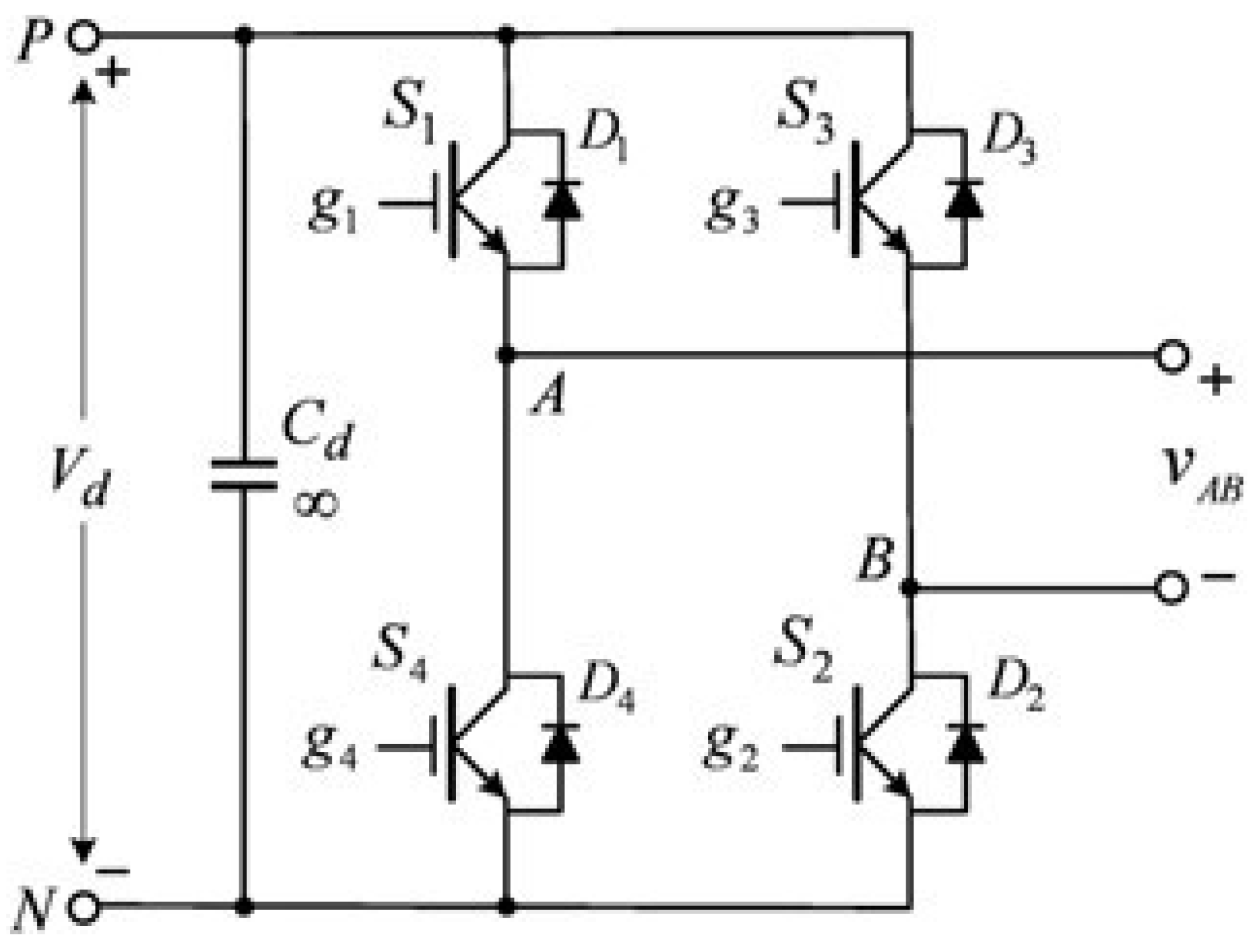
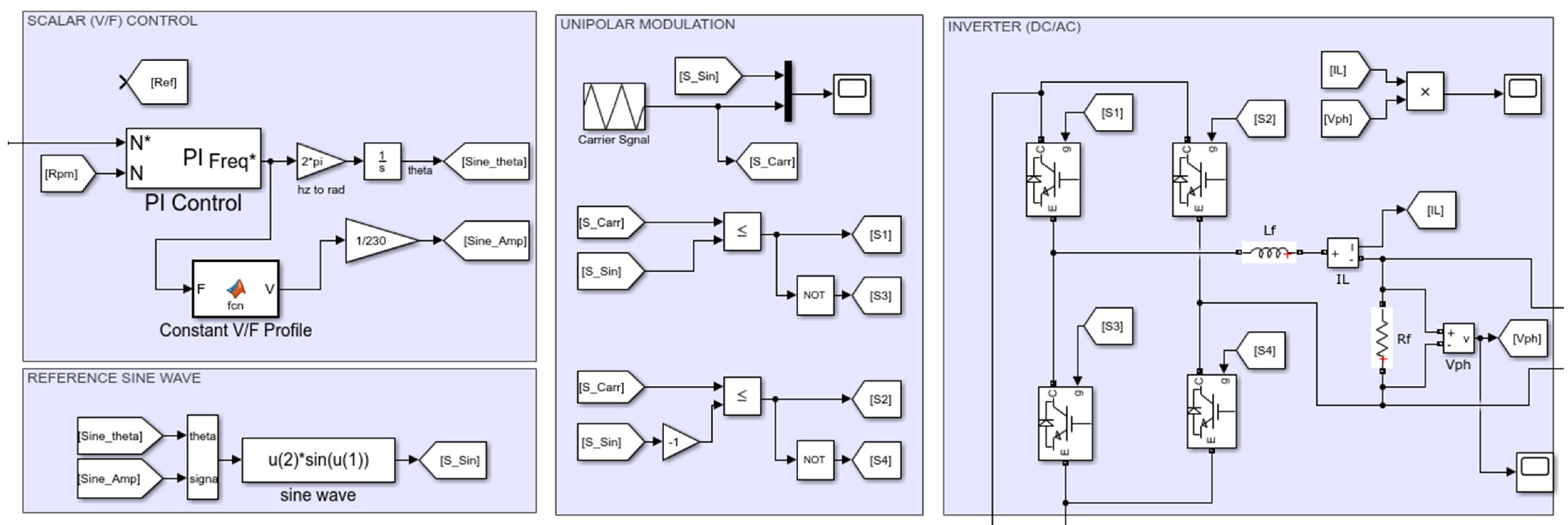
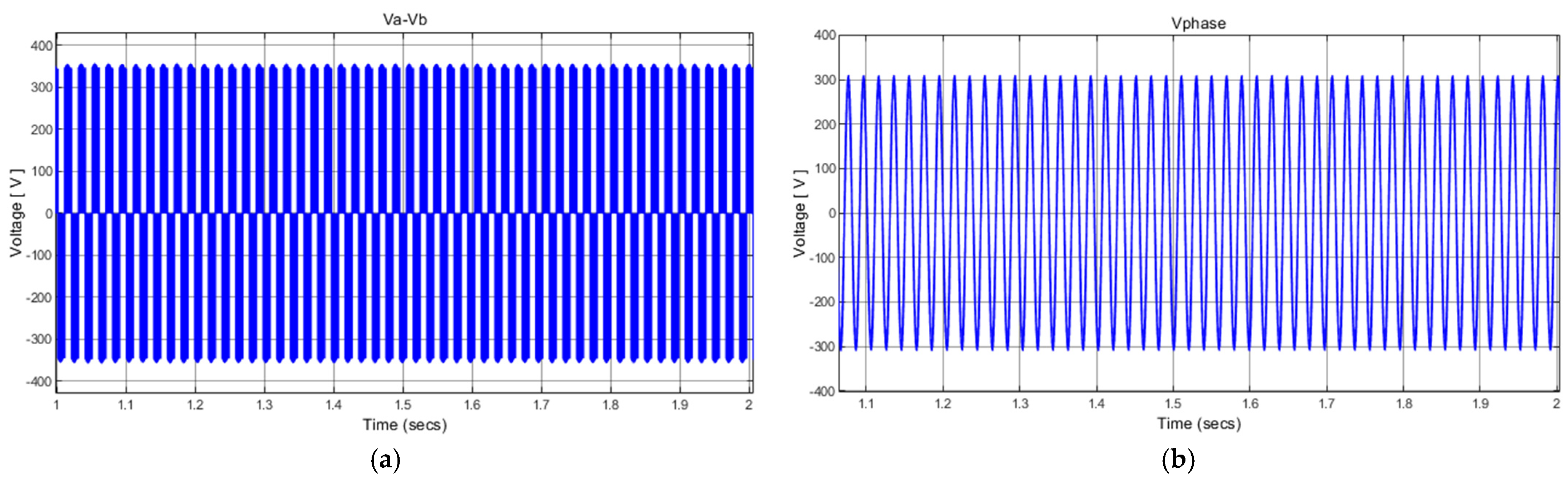
2.4. Inverter and Unipolar Modulation Control

A basic inverter is used to convert direct current (DC) into alternating current (AC). They are classified into two types that are half-bridge and full-bridge inverters, which are also called H-bridge inverters. The output of the inverter is controlled by the sinusoidal PWM that is generated by either of the two basic topologies. For both schemes, the H-bridge inverter circuit remains the same [27]. H-bridge circuit that compromises the IGBT switches for both unipolar and bipolar modulation, as can be seen in Figure 6.
There are two sinusoidal waves in the unipolar modulation technique with 180° out of phase, as seen in Figure 7. These two sinusoidal waves are compared with the triangular wave to generate the switching signal for the switch S1 and S3 switches of the inverter. The upper two switches are not switching simultaneously, which is the main difference between unipolar and bipolar modulation. In bipolar modulation, all the switches are switching at the same time. In unipolar modulation, the output voltage switches between zero to positive half cycle +Vd or between zero to negative half cycle −Vd, which gives reduced switching losses. Over modulation happens when the modulation index is greater than unity [28,29,30].

2.5. V/f Scaler Control of Single-Phase Induction Motor

Single-phase induction machines are widely used in household appliances and small-scale industrial applications. Speed and torque control in these machines are critical for energy efficiency and system performance [31,32]. The scalar control method provides a simple and effective solution for achieving this control. This method maintains the magnetic flux of the motor by keeping the ratio between the stator voltage and frequency constant. This constant ratio ensures that the magnetic flux of the motor remains stable, which is crucial for smooth and efficient operation [33,34,35]. In this section, the mathematical foundations of the scalar control method and the derivation processes of the formulas are examined in detail. The relationship between the magnetic flux (Φ), stator effective voltage (V), and frequency (f) is expressed as in Equation (4).
V = 4.44 × f × N × Φ
Here, N is the number of stator winding turns, and Φ is the magnetic flux. This equation shows that the stator voltage is directly proportional to the frequency and magnetic flux [33]. To keep the magnetic flux constant, the ratio between voltage and frequency must remain constant, as shown in Equation (5).
V f = 4.44 × N × Φ = C o n s t a n t
This relationship indicates that the magnetic flux is directly proportional to the voltage–frequency ratio, as in Equation (6). Furthermore, the torque (T) produced by the motor is directly proportional to the magnetic flux and rotor current. The rotor current (Ir) is also proportional to the magnetic flux [36,37,38]. Therefore, the torque can be expressed as in Equation (7).
Φ V f
T V f × V f = V f 2
It is easily understood from the above equation that the flux and hence the torque can be controlled by the scalar control method.

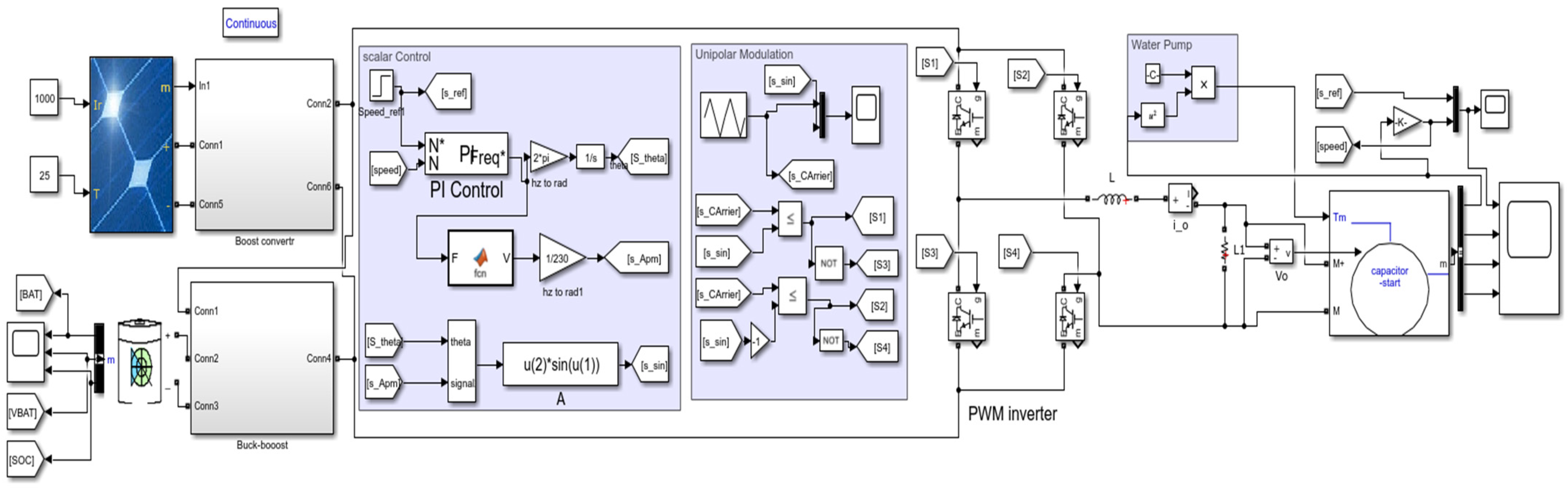
3. The Simulation of the Designed System

The main system design consists of a PV array, a boost converter for MPPT, a buck-boost converter for bidirectional energy transfer, a scaler control and unipolar PWM blocks, a water pump model, and a single-phase induction motor. Its main winding is connected through the inverter output, which gives the voltage input to the motor. The output voltage of the inverter is controlled by the V/f scalar control system, which gives the defined modulation index to control the magnitude of the sine wave to obtain the required output voltage. The speed of the motor is controlled by the closed-loop PI controller, which is given the reference speed. The closed-loop PI controller compares the reference speed with the machine output speed and minimizes the error to obtain almost zero output for the controller error [39,40,41]. The centrifugal pump is taken as the torque load, which is equal to Kp = 9.37. As the machine starts, the load starts increasing with the increase in speed and reaches the maximum value for the given Kp. The main purpose of this system is to make the induction motor run with the required reference speed. The detailed MATLAB/Simulink model of the designed single-phase IM driver for water pumping powered by a PV system is given in Figure 8. The simulation parameters of the PV source and buck-boost converter are given in Table 1.
Figure 9 shows the motor control and driver block diagram in MATLAB/Simulink. In the scalar (V/f) control section, the speed of the motor is compared with the reference speed, and the reference sine wave is generated using the obtained angle and amplitude values. In the unipolar modulation section, this reference sine wave is compared with the triangular carrier wave signal. As a result of this comparison, switching signals are generated for the four switches on the inverter. The input of the inverter block is connected to the DC bus, while its output is connected to the electric motor that drives the water pump.

4. Simulation Results

All the results are explained in graphical form and with their required tags for the operation. The MATLAB/Simulink results are given with the change in irradiation with time; charging and discharging points of the battery are also mentioned. The results below also show the comparison of the induction motor speed with control and without control.

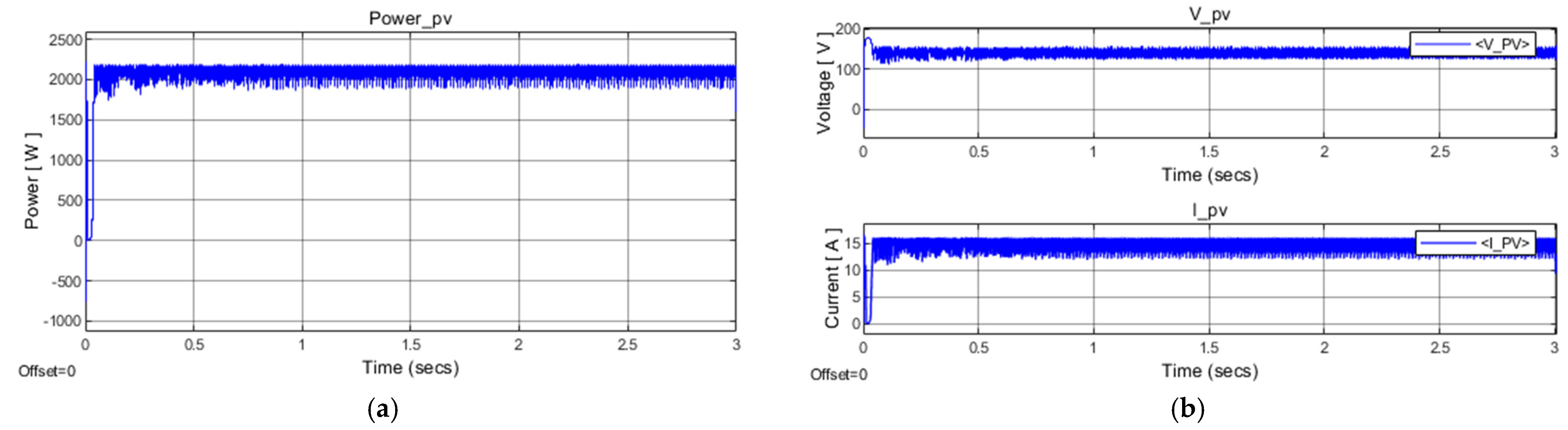
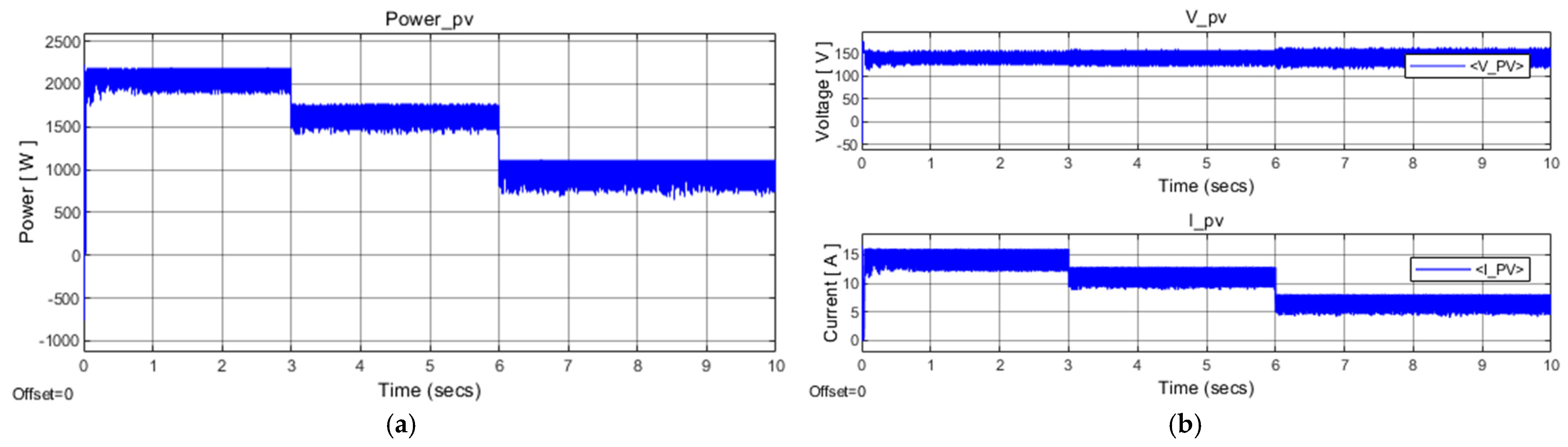
4.1. Simulation Results of PV Array

In this section, all the results obtained by the PV array via the boost converter and the buck-boost converter are shown and discussed with given values. Experiments are performed by changing the irradiance of the PV array. All results are taken for 10 s. In Figure 10a, the voltage output of the boost converter is stable at 325 V with no change in the speed of the motor, showing that there is no fluctuation in the voltage waveform. It stays stable throughout the process. The buck-boost converter supports the boost converter to maintain voltage stability and to charge and discharge the battery. This voltage is later given to a single-phase inverter to convert DC to AC to feed the induction motor, where 230 V rms voltage is required to run the motor with maximum speed.
In Figure 10b, the voltage output of the boost converter is shown. The control mechanism is applied via the PI controller to control the voltage output at 350 V to run the motor smoothly with the variation in speed input. It can be seen in Figure 10b that there is a variation in the voltage output at different times in seconds over the entire 10 s output. When the speed is changed to 1000 rpm at the time of 3 s, the PI controller sets the output again at 350 volts via feedback. The same process repeats itself for a period of 6 s, and again, the PI controller stabilizes the voltage output at 350 V. Due to continuous voltage control, the motor runs smoothly with different input speeds at any period, and it also causes the charge and discharge of the battery.
In Figure 11a, the voltage output of the inverter is shown across leg A and leg B, and the peak value of the voltage is 350 V. The bar of the voltage goes from zero to positive 350 V and again from zero to −350 V according to the single-phase inverter unipolar modulation rule. Figure 11b is the zoom output result of the inverter sinusoidal voltage output waveform with the 230 V rms voltage.
Figure 12a is the power output result of the PV array controlled with MPPT at 1000 W/m2 irradiance and 25 °C temperature. Figure 12b is the voltage (V_PV) and current (I_PV) output results of the PV array controlled with MPPT at 1000 W/m2 irradiance and 25 °C.
Simulation results of the PV array with a change in irradiance are given in this part. Figure 13a is the power output result of the PV array controlled with MPPT at 1000 W/m2, 800 W/m2, and 500 W/m2 irradiance and 25 °C. Figure 13b is the voltage (V_PV) and current (I_PV) output results of the PV array controlled with MPPT at 1000 W/m2, 800 W/m2, 500 W/m2 irradiance, and 25 °C temperature.

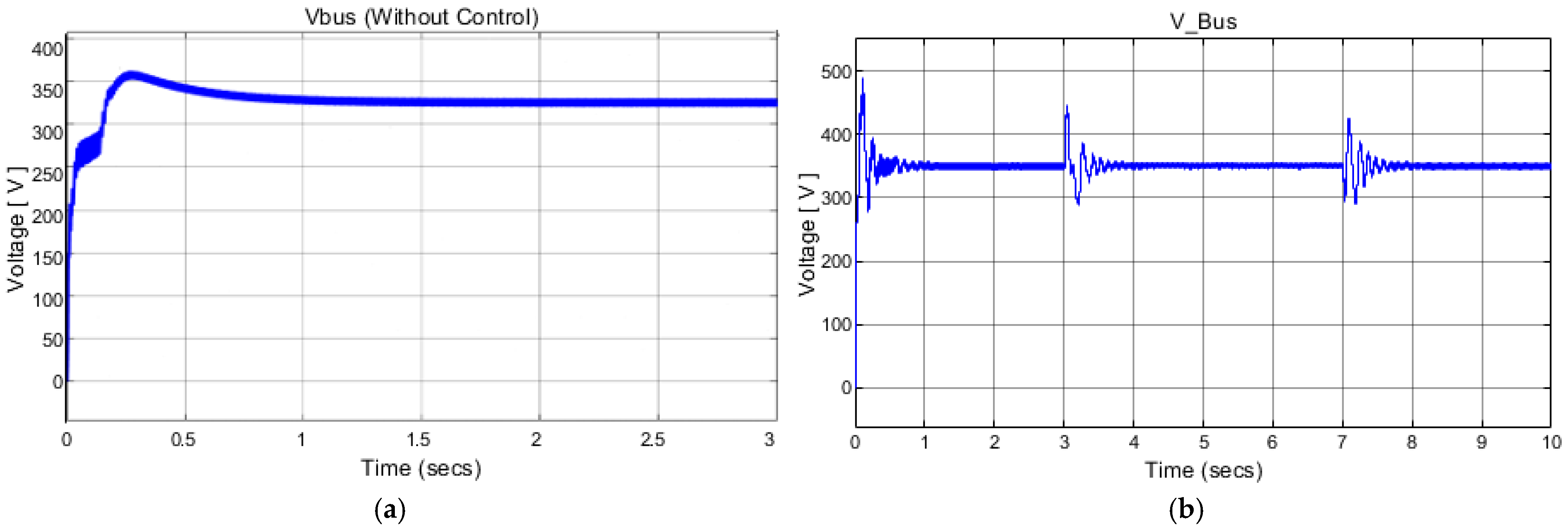
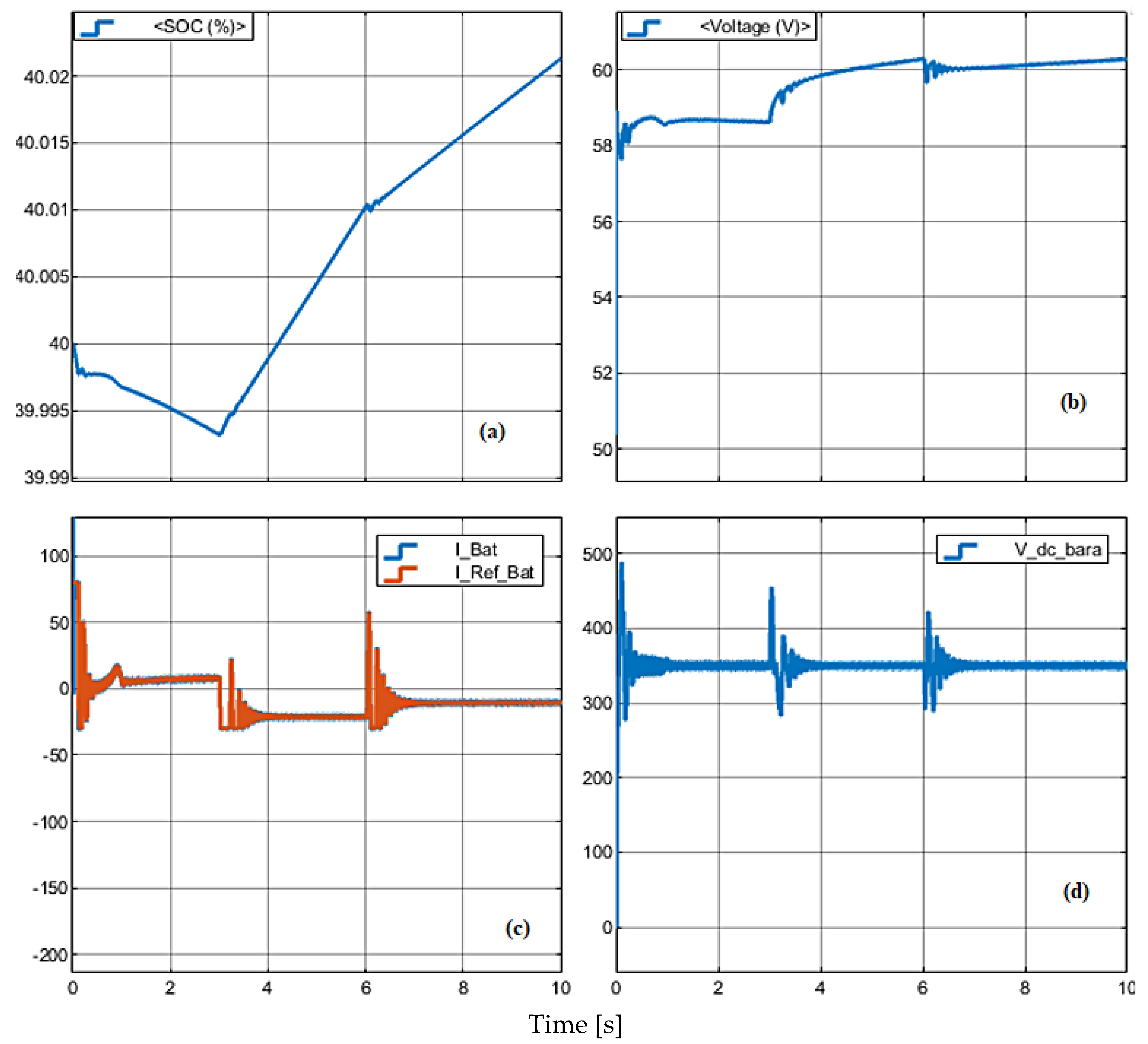
4.2. Simulation Results of Battery Output

In Figure 14, there are the combinations of four different result outputs of the system and simulation results of battery output with a change in motor speed. In Figure 14a, the result of the state of charge (SOC) of the battery is given. From the period of zero to 3 s, the battery shows continuous discharging at 1500 rpm of motor speed, and when the speed goes down to 1000 rpm, the battery starts charging for 6 s. Again from 6 s to 10, the battery keeps on charging with the increase in speed to 1300 rpm. In Figure 14b at the right, the battery voltage keeps on increasing from zero to 10 s, but among the intervals of speed change and charging and discharging of the battery, the voltage increment is a little more while charging the battery as compared with discharge. In Figure 14c, the left-down battery current is shown with the reference value of the controlled battery current via the PI controller, which keeps on following the output battery current of the buck-boost converter. At the start, when the battery is discharging, the current increases, and while charging, the current keeps on decreasing at all three variable points in time. Figure 14d shows the voltage output of the boost converter, which is controlled by the PI controller to give a stable 350 V output.
In Figure 15, the combination of four different result outputs of the system simulation results of battery output with a change in irradiation is given. In Figure 15a, the result of the state of charge (SOC) of the battery. From the time of zero to 3 s, the battery shows continuous discharging at the 1000 W/m2, and when the speed goes down to 1000 rpm, and the irradiance also decreases from 1000 to 800 W/m2, the battery starts charging for 6 s. Again from 6 s to 10 s, the battery starts discharging with an increase in speed to 1300 rpm and a decrease in irradiance to 500 W/m2. In Figure 15b, the right battery voltage has a little increment from zero to 3 s and then starts increasing at 1500 rpm and 1000 W/m2. After that, from 3 s to 6 s, voltage starts increasing at 1000 rpm and 800 W/m2. From 6 s to 10 s again, it starts decreasing at 500 W/m2. In Figure 15c, the left-down battery current is shown with the reference value of the controlled battery current via the PI controller, which keeps on following the output battery current of the buck-boost converter. At the start, when the battery is discharging, the current increases, and while charging, the current keeps on decreasing from 3 s to 6 s, and again, at the irradiance of 500 W/m2, the current starts increasing. Figure 15d shows the voltage output of the boost converter, which is controlled by the PI controller to give a stable 350 V output. When the speed and irradiation values change, the system dynamically responds and reaches the reference values. During this dynamic behavior, short-term fluctuations have occurred in the current and DC bus voltage, as shown in Figure 14 and Figure 15.

4.3. Simulation Results of SPIM

Simulation results of SPIM at variable irradiance input were investigated secondly. In Figure 16, the speed of SPIM changes from 1500 rpm to 1000 rpm and then at the end from 1000 rpm to 1300 rpm at 3 s and 6 s at the same period; the irradiance changes from 1000 W/m 2 to 800 W/m2 and at the end to 500 W/m2.
Simulation results of the speed output of SPIM without the controller and motor main winding current output are given in Figure 17a,b.

4.4. Comparison of Simulation Numerical Results

In this section, for different parameters, simulation results are compared numerically. Power flow analysis for different motor speeds and solar irradiance at 25 °C is given in Table 2. Power flow analysis for different motor speeds and temperatures at 1000 W/m2 irradiance is given in Table 3. Negative power indicates that the battery is charging, while positive power indicates that it is discharging. The efficiency of the system is compared for different parameters in two tables. However, 800 W/m2 solar irradiance and 25 °C in Table 2 is the best efficiency, while 1000 W/m2 solar irradiance and 50 °C in Table 3 is seen as the best efficiency for a 1000 rpm motor speed.

5. Conclusions

The desired work deals with the photovoltaic (PV) powered induction motor water pump system. In this system, the single-phase induction motor drive (IMD) is fed by the voltage source inverter to run and analyze the centrifugal water pump performance by providing the DC source through the DC boost converter. The MATLAB/Simulink software is used for all analyses and performances. It is observed that the performance of the IMD is much better with the closed-loop scalar control system and the V/f control system. This work has shown that the single-phase induction motor has sufficient performance to run the water pump. The scalar control system made the control process easy and simple, which reduces the system’s loss and complexity. Due to the low starting torque characteristic of single-phase IMD, it reaches the control level faster as compared with other motors.
The future aim of this study is experimental results can justify the simulation results to the smart grid-connected system that may replace the standalone system. Also, MPPT and some other configurations can replace the PI controller in a DC–DC converter system to obtain better output results. Other different control techniques can be applied, such as vector control or direct torque control, to obtain better outputs. Moreover, an experimental system can be installed in integration with smart grid systems in the irrigation system, which can be controlled by adaptive control strategies. To determine the humidity, temperature, motor speed, irradiance level, amount of water to deliver or to fill the water tank, and many more according to the requirement.

Author Contributions

Methodology, S.F.A.B., H.K. and M.E.Ş.; Resources, S.F.A.B.; Writing—original draft, S.F.A.B.; Writing—review and editing, H.K. and M.E.Ş.; Supervision, H.K. and M.E.Ş. All authors have read and agreed to the published version of the manuscript.

Funding

This research received no external funding.

Data Availability Statement

The data presented in this study are available on request from the corresponding authors.

Acknowledgments

This study is based on the master thesis of the first author at Karadeniz Technical University, Trabzon, Turkey. The authors wish to thank the Presidency of Turks Abroad and Related Communities (YTB) scholarship for the master student support 14PK272381 scholar number.

Conflicts of Interest

The author declares no conflicts of interest.

Abbreviations

The following abbreviations are used in this manuscript:
MPPTMaximum power point tracking
IMDInduction motor driver
SVPWMSpace vector pulse width modulation
VSIVoltage source inverter
SPIMSingle-phase induction motors
SPVWPSolar photovoltaic water pumping
PVWPPhotovoltaic water pumping
SNLSandia National Laboratories
V/fVoltage/frequency
SPWMSine pulse width modulation
P–OPerturb and observe
INCIncremental conductance
SOCState of charge
CCMContinuous current mode

References

  1. Bukhari, S.F.A. Transformerless Photovoltaic System Fed Single Phase Induction Motor Driver for Water Pumping. Master’s Thesis, Karadeniz Technical University, Trabzon, Turkiye, 2020. [Google Scholar]
  2. Liu, B.; Mei, S.; Jian, Y.; Dongran, S.; Deqiang, H.; Shaojian, S. Combined reactive power injection modulation and grid current distortion improvement approach for H6 transformer-less photovoltaic inverter. IEEE Trans. Energy Convers. 2017, 32, 1456–1467. [Google Scholar] [CrossRef]
  3. Satpathy, S. Photovoltaic Power Control Using MPPT and Boost Converter. Ph.D. Thesis, National Institute of Technology, Rourkela, India, 2012. [Google Scholar]
  4. Yağcı, B.E.; Demirsoy, G.; Akpolat, A.N. General overview of artificial neural network applications in renewable energy systems. Turk. J. Electromechanics Energy 2024, 9, 95–107. [Google Scholar]
  5. Tang, Y.; Wenli, Y.; Poh, C.; Frede, B. Highly reliable transformerless photovoltaic inverters with leakage current and pulsating power elimination. IEEE Trans. Ind. Electron. 2016, 63, 1016–1026. [Google Scholar] [CrossRef]
  6. Kumar, K.; Kalyan, R.; Hemanth, K. Implementation of MPPT algorithm for solar photovoltaic cell by comparing short-circuit method and incremental conductance method. Procedia Technol. 2014, 12, 705–715. [Google Scholar] [CrossRef]
  7. Akın, E.; Şahin, M.E. Investigation of Incremental Conductance MPPT Algorithm in MATLAB/Simulink Using Photovoltaic Powered DC-DC Boost Converter. In Proceedings of the 22nd International Symposium on Power Electronics, Novi Sad, Serbia, 25–28 October 2023; Volume 1, pp. 1–6. [Google Scholar]
  8. Freris, L.; David, I. Renewable Energy in Power Systems; John Wiley & Sons: Hoboken, NJ, USA, 2008. [Google Scholar]
  9. Kumar, R.; Singh, B. Solar PV powered BLDC motor drive for water pumping using Cuk converter. IET Electr. Power Appl. 2017, 11, 222–232. [Google Scholar] [CrossRef]
  10. Harjai, A.; Bhardwaj, A.; Sandhibigraha, M. Study of Maximum Power Point Tracking (MPPT) Techniques in a Solar Photovoltaic Array. Ph.D. Thesis, National Institute of Technology, Rourkela, India, 2011. [Google Scholar]
  11. Lindholm, F.A.; Fossum, J.G.; Burgess, E.L. Application of the superposition principle to solar-cell analysis. IEEE Trans. Electron Devices 1979, 26, 165–171. [Google Scholar] [CrossRef]
  12. Rekioua, D.; Matagne, E. Optimization of Photovoltaic Power Systems: Modelization, Simulation and Control; Springer Science & Business Media: Berlin/Heidelberg, Germany, 2012. [Google Scholar]
  13. Meah, K.; Ula, S.; Barrett, S. Solar photovoltaic water pumping-opportunities and challenges. Renew Sustain. Energy Rev. 2008, 12, 1162–1175. [Google Scholar] [CrossRef]
  14. Short, T.D.; Thompson, P. Breaking the mould: Solar water pumping-the challenges and the reality. Sol. Energy 2003, 75, 1–9. [Google Scholar] [CrossRef]
  15. Foster, R.; Cota, A. Solar water pumping advances and comparative economics. Energy Procedia 2014, 57, 1431–1436. [Google Scholar] [CrossRef]
  16. Pullenkav, T. Solar Water Pumping for Irrigation: Opportunities in Bihar, Deutche Gesellschaft fur Internationale Zusammenarbeit (GIZ) GmbH, Indo-German Energy Programme. 2013. [Google Scholar]
  17. Foster, R.; Hanley, C. Life cycle cost analysis for photovoltaic water pumping systems in Mexico. In Proceedings of the 2nd World Conference on Photovoltaic Energy Conversion, Vienna, Austria, 6–10 July 1998. [Google Scholar]
  18. Reca-Cardeña, J.; López-Luque, R. Design principles of photovoltaic irrigation systems. In Advances in Renewable Energies and Power Technologies; Elsevier: Amsterdam, The Netherlands, 2018; pp. 295–333. [Google Scholar]
  19. Şahin, M.E.; Blaabjerg, F. A hybrid PV-battery/supercapacitor system and a basic active power control proposal in MATLAB/Simulink. Electronics 2020, 9, 129. [Google Scholar] [CrossRef]
  20. Željko, V. Despotović, Hybrid “Off-Grid” Power Supply Systems and Their Applications in Agriculture: Practical Realizations. In Proceedings of the 10th ICREPS Conference (MKOIEE 10.1), Belgrade, Serbia, 17–18 October 2022; pp. 17–33. [Google Scholar]
  21. Chandel, S.; Naik, M.N.; Chandel, R. Review of solar photovoltaic water pumping system technology for irrigation and community drinking water supplies. Renew. Sustain. Energy Rev. 2015, 49, 1084–1099. [Google Scholar] [CrossRef]
  22. Buldu, İ.; Şahin, M.E. A MATLAB/GUI Based Photovoltaic System Simulator for Estimation of PV Parameter using Newton-Raphson Method. Gazi J. Eng. Sci. 2021, 7, 196–212. [Google Scholar]
  23. Rashid, M.H. Power Electronics, Circuits, Devices, and Applications, 3rd ed.; Pearson Education, Inc.: San Francisco, CA, USA, 2004. [Google Scholar]
  24. Chao, K.H.; Tseng, C.; Huang, H.; Liu, G. Design and Implementation of a Bidirectional DC-DC Converter for Stand-Alone Photovoltaic Systems. Int. J. Comput. Consum. Control 2013, 2, 44–45. [Google Scholar]
  25. Edelmoser, K.H.; Himmelstoss, F.A. Bidirectional DC-to-DC Converter for Solar Battery Backup Applications. In Proceedings of the IEEE 35th Annual Power Electronics Specialists Conference, Aachen, Germany, 20–25 June 2004; Volume 6, pp. 2070–2074. [Google Scholar]
  26. Şahin, M.E.; Blaabjerg, F. PV-powered hybrid energy storage system control using bidirectional and boost converters. Electr. Power Compon. Syst. 2022, 49, 1260–1277. [Google Scholar] [CrossRef]
  27. Liu, C.; Wu, B.; Cheung, R. Advanced algorithm for MPPT control of photovoltaic systems. In Proceedings of the Canadian Solar Buildings Conference, Montreal, Canada, 20–24 August 2004; pp. 20–24. [Google Scholar]
  28. Jeevan, K.; Soumitra, K. Study of single-phase voltage source inverter with SPWM and PWM techniques. Int. J. Curr. Eng. Sci. Res. (IJCESR) 2018, 5, 2. [Google Scholar]
  29. Namboodiri, A.; Wani, H.S. Unipolar and bipolar PWM inverter. Int. J. Innov. Research Sci. Technol. 2014, 1, 237–243. [Google Scholar]
  30. Sultani, J.F. Modelling Design and Implementation of DQ Control in Single-Phase Grid-Connected Inverters for Photovoltaic Systems Used in Domestic Dwellings. Ph.D. Thesis, De Montfort University, Leicester, UK, 2013. [Google Scholar]
  31. Ismail, B.; Taib, S.; Saad, A.M.; Isa, M.; Hadzer, C.M. Development of a single phase SPWM microcontroller-based inverter. Int. Power Energy Conf. 2006, 11, 437–440. [Google Scholar]
  32. Manfo, T.A.; Şahin, M.E. Development of an Automatic Photovoltaic Cell-Battery Powered Water Irrigation System Incorporated with Arduino Software for Agricultural Activities. Gazi Mühendislik Bilim. Derg. 2024, 10, 314–328. [Google Scholar] [CrossRef]
  33. Habbi, H.M.D.; Ajeel, H.J.; Ali, I.I. Speed control of induction motor using PI and V/F scalar vector controllers. Int. J. Comput. Appl. 2016, 151, 36–43. [Google Scholar]
  34. Ioannides, M.G. Design and implementation of PLC-based monitoring control system for induction motor. IEEE Trans. Energy Convers. 2004, 19, 469–476. [Google Scholar] [CrossRef]
  35. Maria, G.I.; Papazis, S.A.; Ioannidou, F.G. Implementation of a scalar control scheme for variable frequency induction motor actuator system. Sens. Actuators Phys. 2003, 106, 306–309. [Google Scholar]
  36. Boldea, I.; Moldovan, A.; Tutelea, L. Scalar V/f and I-f control of AC motor drives: An overview. In Proceedings of the 2015 International Aegean Conference on Electrical Machines & Power Electronics (ACEMP), 2015 International Conference on Optimization of Electrical & Electronic Equipment (OPTIM) & 2015 International Symposium on Advanced Electromechanical Motion Systems (ELECTROMOTION), Side, Turkey, 2–4 September 2015; pp. 8–17. [Google Scholar]
  37. Akin, B.; Garg, N. Scalar (V/f) Control of 3-Phase Induction Motors; Texas Instruments Incorporated: Dallas, TX, USA, 2013. [Google Scholar]
  38. Peña, J.M.; Díaz, E.V. Implementation of V/f scalar control for speed regulation of a three-phase induction motor. In Proceedings of the 2016 IEEE ANDESCON, Arequipa, Peru, 19–21 October 2016; pp. 1–4. [Google Scholar]
  39. Waleed, U.; Waseem, M.; Shaukat, H.; Ijaz, A.; Almalaq, A.; Mohamed, M.A. An Efficient FPGA Based Scalar V/f Control Mechanism of Three Phase Induction Motor for Electric Vehicles. In Proceedings of the 2021 31st Australasian Universities Power Engineering Conference (AUPEC), Perth, Australia, 26–30 September 2021; pp. 1–6. [Google Scholar]
  40. Rekioua, D.; Zaouche, F.; Mokrani, Z.; Rekioua, T.; Logerais, P.O. Power management control for photovoltaic water pumping system in Agriculture. Turk. J. Electromechanics Energy 2023, 8, 109–117. [Google Scholar]
  41. Vostrov, K. Synchronous Machine Vector Control System Development and Implementation. Master’s Thesis, Lappeenranta University of Technology, Lappeenranta, Finland, 2016. [Google Scholar]
Figure 1. The designed solar water pump system.
Electronics 14 01189 g001
Figure 2. Designed a PV-powered water pumping system basic model.
Electronics 14 01189 g002
Figure 3. (a) The PV cell equivalent electric circuit, (b) Current-voltage and power-voltage characteristics of PV array, (c) Flow chart of INC MPPT algorithm [16,24,25].
Electronics 14 01189 g003
Figure 4. DC to DC Boost converter circuit.
Electronics 14 01189 g004
Figure 5. (a) A bidirectional DC–DC converter circuit, (b) charging, (c) discharging mode.
Electronics 14 01189 g005
Figure 6. Single-phase H-Bridge inverter.
Electronics 14 01189 g006
Figure 7. Waveforms of the unipolar modulation scheme.
Electronics 14 01189 g007
Figure 8. Designed a PV-powered water pumping system in MATLAB/Simulink.
Electronics 14 01189 g008
Figure 9. The motor control and driver block diagram in MATLAB/Simulink.
Electronics 14 01189 g009
Figure 10. (a) PV array voltage output, (b) voltage output of boost converter.
Electronics 14 01189 g010
Figure 11. (a) Inverter voltage across leg A and leg B, (b) Sinusoidal voltage output.
Electronics 14 01189 g011
Figure 12. (a) The power output of PV array, (b) PV current and voltage waveform at 1000 W/m2 and 25 °C.
Electronics 14 01189 g012
Figure 13. (a) PV power output, (b) PV current and voltage waveform at 1000 W/m2, 800 W/m2, 500 W/m2 irradiance, and 25 °C.
Electronics 14 01189 g013
Figure 14. Battery output, (a) charging and discharging mode, (b) battery voltage, (c) battery current, (d) DC bus voltage at 1500 rpm (0–3 s), 1000 rpm (3–6 s), and 1300 rpm (6–10 s).
Electronics 14 01189 g014
Figure 15. Battery output, (a) Charging and discharging mode, (b) Battery voltage, (c) Battery current, (d) DC bus voltage at 1500 rpm and 1000 W/m2 (0–3 s), 1000 rpm and 800 W/m2 (3–6 s), 1300 rpm and 500 W/m2 (6–10 s).
Electronics 14 01189 g015
Figure 16. SPIM simulation output, (a) Motor speed, (b) Torque, (c) Auxiliary winding current, (d) Main winding current at 1500 rpm and 1000 W/m2 (0–3 s), 1000 rpm and 800 W/m2 (3–6 s), 1300 rpm and 500 W/m2 (6–10 s).
Electronics 14 01189 g016
Figure 17. (a) Speed output without controller at 1365 rpm, (b) Main winding current (I).
Electronics 14 01189 g017
Table 1. The simulation parameters of the PV source, converter, and motor.
PV Source Parameters and Values
ParametersValue
Open circuit voltage (Voc)44.3 V
Short circuit current (Isc)8.25 A
Voltage at maximum power (Vmp)35.5 V
Cells per module72
Current at maximum power Imp (A)7.6 A
Maximum power (W)269.8 W
Converters Parameters and Values
ParametersValue
Input capacitor of boost converter100 µF
Inductor of the boost converter1.8 mH
Output capacitor of boost converter1500 µF
Input capacitor of buck-boost converter1000 µF
Inductor of the buck-boost converter1 mH
Output capacitor of buck-boost converter1000 µF
Motor Parameters and Values
ParametersValue
Motor power2000 W
Number of poles4-Pole
Motor speed1440 rpm
Main winding stator resistance0.602 Ω
Stator inductance7.4 mH
Rotor resistance1.012 Ω
Rotor inductance5.6 mH
Auxiliary winding resistance7.14 Ω
Auxiliary winding inductance8.5 mH
Table 2. Power flow analysis for different motor speeds and solar irradiance at 25 °C.
System ParametersSteady State Conditions (25 °C)
Solar Irradiance (W/m2)1000800500
Motor Speed (rpm)150010001300
PV System Power (W)19971610.5941
Battery Power (W)29.5−876385.5
SPIM Power Output (W)1647510.51108
Efficiency (%)81.386.183.5
Table 3. Power flow analysis for different motor speeds and temperatures at 1000 W/m2 irradiance.
System ParametersSteady State Conditions (1000 W/m2)
Solar Temperature (°C)755025
Motor Speed (rpm)150010001300
PV System Power (W)159418462058.5
Battery Power (W)444.5−1080−630
SPIM Power Output (W)1647510.51108
Efficiency (%)80.886.284.4
Disclaimer/Publisher’s Note: The statements, opinions and data contained in all publications are solely those of the individual author(s) and contributor(s) and not of MDPI and/or the editor(s). MDPI and/or the editor(s) disclaim responsibility for any injury to people or property resulting from any ideas, methods, instructions or products referred to in the content.

