Article

Hybrid Control Strategy for DC Microgrid Against False Data Injection Attacks and Sensor Faults Based on Lagrange Extrapolation and Voltage Observer

1
Department of Electrical and Information Engineering, Research Center for Electrical and Information Technology, Seoul National University of Science and Technology, 232 Gongneung-ro, Nowon-gu, Seoul 01811, Republic of Korea
2
Purpose Built Mobility Group, Korea Institute of Industrial Technology, 6 Choemdan-gwagiro 208-gil, Buk-gu, Gwangju 61012, Republic of Korea
*
Author to whom correspondence should be addressed.
Electronics 2025, 14(6), 1087; https://doi.org/10.3390/electronics14061087
Submission received: 3 February 2025 / Revised: 1 March 2025 / Accepted: 6 March 2025 / Published: 10 March 2025
(This article belongs to the Special Issue Power Electronics and Renewable Energy System)

Abstract

:
In this study, to enhance the system reliability under false data injection (FDI) attacks and DC-link voltage (DCLV) sensor failures, a hybrid control strategy for a DC microgrid (DCMG) based on the Lagrange extrapolation and voltage observer is proposed. Under normal conditions without FDI attacks or DCLV sensor failures, the DCMG system works in a distributed control scheme. To enhance the reliability of the system under the DCLV sensor failure or FDI attack, the DCMG system utilizes a hybrid control strategy that combines distributed control with decentralized control. The hybrid control strategy is achieved by the proposed detection algorithms for FDI attacks and DCLV sensor failures. The detection of FDI attacks is accomplished by comparing the predicted secondary controller output based on the Lagrange extrapolation with the actual one. When a power agent detects an FDI attack, its control mode is switched to decentralized control by using the proposed hybrid control strategy. The DCLV sensor failure detection algorithm to enhance system reliability against DCLV sensor failures is achieved by comparing the estimated DCLV with the measured one from the voltage observer. Upon detecting a DCLV sensor failure, the operation of the power agent is switched to the current control mode to sustain the system operation even under DCLV sensor failures. The proposed detection algorithms are simple, effective, and precise, operating without mutual interference that deteriorates the detection accuracy. Simulation and experiments are carried out under various uncertain test conditions to validate the reliability and effectiveness of the proposed control strategy.

1. Introduction

The increasing severity of environmental issues, such as global warming, air pollution, and resource depletion, has prompted an urgent need for reliable and efficient approaches to meet the increasing global energy demand [1]. Fossil fuels, which currently dominate global energy consumption, are not only finite resources but also significant contributors to greenhouse gas emissions [2]. To overcome these challenges, renewable energy sources (RESs) have become increasingly important. However, there exists the intermittent nature of RESs which poses substantial challenges such as reliability issues and difficulty in maintaining a stable energy supply. Due to this reason, microgrids that integrate RESs, energy storage systems (ESSs), utility grids, and local loads have gained lots of interest as a key solution to overcome such limitations and enhance reliability [3].
The substantial generation of DC power from RESs, including fuel cells, wind turbines, and photovoltaics (PV), along with the increasing demand for DC loads, has accelerated the rapid development of DCMGs [4]. In general, DCMGs can avoid the issues related to reactive power regulation and frequency synchronization. Therefore, designing control schemes for DCMGs faces fewer technical challenges as compared to doing so for AC microgrids (ACMGs) [5,6,7,8]. Nevertheless, there is still a need to achieve a power balance between the supply and demand in DCMG systems. Without proper control and power management, both renewable energy generation intermittency and load fluctuation may cause an instantaneous power imbalance, which in turn would deteriorate the DC-link voltage (DCLV) regulation performance and power quality [9].
Based on the structure of digital communication links (DCLs), various methods have been employed to achieve power management for DCMG systems, which are classified as centralized, decentralized, and distributed controls [10,11]. The centralized control method relies on a central controller that communicates with all power agents through DCLs to decide the power agent operations [12]. The centralized control scheme is effective and straightforward. However, it has limitations such as a significant communication burden, complex computations, and high system costs. In addition, the central controller not only has a high risk of a single point of failure, but also requires a modification of the control structure when a new energy source is added or the existing energy source is removed [13,14]. On the other hand, the decentralized control method determines its operation mode without using the central controller and DCLs. This method provides multiple benefits in terms of low system cost and high scalability. However, due to the absence of DCLs, there exists a system reliability issue under the agent power variation in the decentralized control method. To overcome this limitation, a distributed control method can be potentially considered as an alternative solution. In a distributed DCMG system, the power agents independently determine appropriate operation modes with a limited DCL structure without depending on a central controller [15,16,17].
Generally, a hierarchical control structure has been employed widely for power sharing as well as voltage regulation in a distributed DCMG system [18,19,20]. In the primary control, a droop control scheme is typically implemented to regulate the current of each distributed generation (DG) according to a predefined ratio. In the droop control scheme, high droop gain improves power sharing accuracy but leads to a large DCLV deviation [21,22,23]. In the secondary control layer, distributed secondary controllers are normally designed to eliminate DCLV errors [18]. In the study [20], an adaptive event-triggered control method is studied for hierarchical control to guarantee proportional load and voltage regulation even under various disturbances. Although this research effectively achieves both power balance and voltage regulation, it has not considered cyber attacks and sensor faults, which may critically affect the system’s stability and reliability.
Communication among power sources in a distributed DCMG system is quite vulnerable to cyber attacks. A false data injection (FDI) is known to be one of the most common cyber attacks. The main aim of FDI attacks is to illegally modify information such as the voltage and secondary output data during network communication [24]. To ensure the stability of a distributed DCMG system in the presence of cyber attacks, the research in [25] proposes an adaptive compensation term that effectively eliminates the FDI attack signal. An adaptive sliding mode control is also presented in [26] to enhance the resilience of DCMG systems against FDI attacks. This approach reduces the effect of FDI attacks through the design of a robust sliding surface in the secondary control layer. Although the above mentioned approaches have effectively addressed the vulnerability to cyber attacks, the issue of sensor faults in a DCMG system has not been considered.
Sensor faults are also a primary reason to reduce the reliability of a DCMG system. Due to the inherent characteristic of a distributed control scheme which heavily relies on the interactions with neighboring power agents, sensor faults negatively impact the system operation and cause a significant risk in DCMG systems [27]. To overcome the risk caused by the sensor faults, a dual-extended Kalman filter which estimates DCMG system states and faults simultaneously is proposed in [28]. Although this method effectively enhances fault tolerance for the DCMG system, the simultaneous operation of dual-extended Kalman filters increases the complexity and computational burden. The research in [29] presents sensor fault detection in a DCMG system based on an unknown input observer. Despite the effective detection of sensor faults, the unknown input observer is highly sensitive to noise and needs high computation. A hardware redundancy method by using additional sensors has been presented for a DCMG system in [27] to deal with sensor faults. Even though this approach improves the system reliability under sensor failures, the increase in the overall system cost is unavoidable.
Motivated by such concerns, this study proposes a hybrid control strategy for a DCMG to improve the system’s reliability under both FDI attacks and sensor faults. To guarantee both the voltage regulation and power balance under FDI attacks, an FDI detection algorithm is achieved by the Lagrange extrapolation scheme. To detect FDI attacks based on the third-order Lagrange extrapolation, power agents collect the previous outputs of the distributed secondary controller which are used to predict the next-step secondary control output. By comparing the predicted and actual secondary control outputs, FDI attacks can be detected in the proposed scheme. Once FDI attacks are clearly identified, the control modes of power agents are properly changed to continuously achieve power management. Furthermore, to improve the stability and reliability of a DCMG system under DCLV sensor failures, a DCLV sensor failure detection algorithm which is achieved by comparing estimated DCLV and measured one with the voltage observer is also proposed in this paper. FDI detection and DCLV sensor failure detection work independently and simultaneously without affecting the detection accuracy of each other.
To enhance the system’s reliability under both FDI attacks and DCLV sensor failures, this study employs a hybrid control strategy that combines distributed and decentralized control methods. In the absence of any cyber attacks and sensor faults, a distributed control strategy is utilized with a hierarchical structure consisting of primary and secondary control layers. The droop control is implemented for power sharing in the primary control layer and the distributed consensus algorithm is implemented for the DCLV regulation in the secondary control layer. As soon as an FDI attack happens in any power agent, the proposed hybrid control scheme adopts a decentralized control strategy to ensure continuous and stable power sharing by isolating the affected DCL. In this decentralized control strategy, a hierarchical control structure for DCLV regulation and power sharing is still maintained. On the other hand, when a power agent has a DCLV sensor failure, its operation is shifted to the current control mode because the power agent having DCLV sensor failures is unable to regulate the DCLV. By detecting the DCLV sensor failure and selecting proper control modes for the power agents, the proposed method can achieve a stable and reliable operation of the DCMG system under sensor fault conditions. The key contributions of this work are outlined as follows:
(i)
The proposed detection algorithm effectively identifies both sensor faults and FDI attacks independently and simultaneously without affecting the detection accuracy of each other. In the proposed scheme, third-order Lagrange extrapolation and voltage observer are utilized to monitor the abnormalities in the DCLV sensors and DCLs, respectively. The proposed approach is simple and precise without mutual interference which degrades the accuracy of other detection algorithms. As a result, the proposed identification algorithms play a critical role in enhancing a DCMG system’s reliability against potential system disruptions.
(ii)
To maintain the DCMG system stability even under FDI attacks and DCLV sensor failures, a hybrid control strategy is proposed by combining the decentralized and distributed control methods for achieving power management. Upon detecting the FDI attacks, the power agent operation is changed to the decentralized control mode to eliminate the negative impact of FDI attacks. On the other hand, when the voltage sensor fault occurs in a power agent, the corresponding power agent shifts the operation to the current control mode because the voltage control is not possible. This hybrid approach enables the DCMG system to operate continuously even under such emergency conditions by properly changing the operation modes of power agents.
(iii)
Finally, a series of simulations and experimental tests are conducted to demonstrate the feasibility of the proposed hybrid control strategy. In particular, to highlight the robustness and reliability of the proposed strategy, the proposed DCMG system has been evaluated under various conditions, including normal operation, FDI attacks in DCLs, and DCLV sensor failures. It is confirmed from these test results that the proposed scheme effectively maintains voltage regulation and power balance in the presence of FDI cyber attacks and sensor faults.
The structure of this paper is as follows: Section 2 outlines the system configuration of a DCMG system. Section 3 describes the proposed hybrid control strategy for power agents under FDI attacks and sensor faults in detail. Section 4 and Section 5 present the simulation and experimental test results under various conditions. Lastly, Section 6 gives the conclusion of this study.

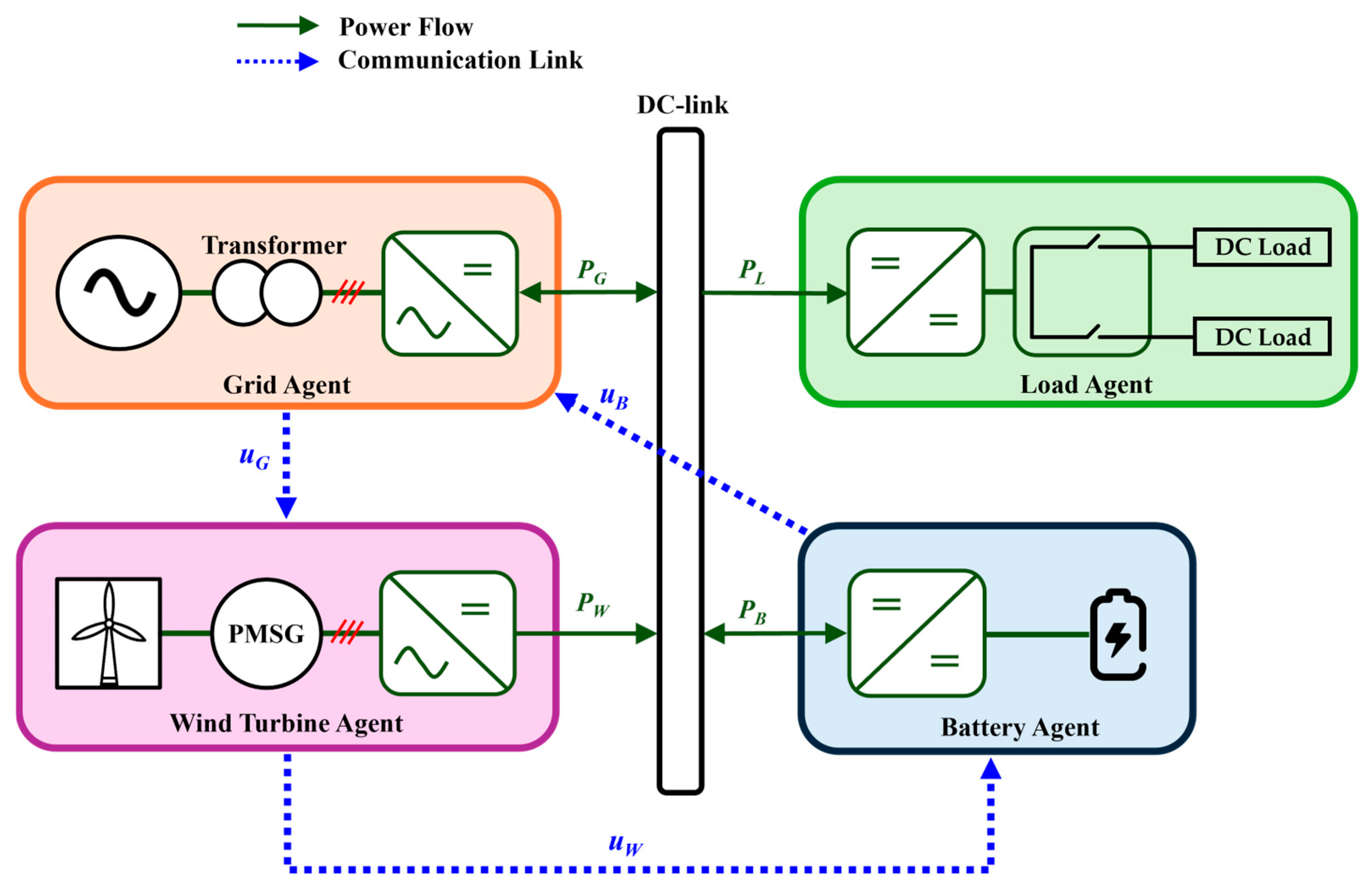
2. Description of Distributed DCMG System

Figure 1 depicts the system configuration of a distributed DCMG, which includes four power agents: a battery agent, a grid agent, a wind turbine agent, and a load agent. The grid agent links the main grid to the DC-link via a bidirectional AC/DC converter. The wind turbine agent converts the mechanical energy from the wind turbine to electrical energy using a permanent magnet synchronous generator (PMSG) to interface with the DC-link via a unidirectional AC/DC converter. The battery agent is connected to the DC-link through a bidirectional DC/DC converter, enabling power exchange. The load agent comprises the DC loads that are connected to the DC-link directly.
In the DCMG, the grid and battery agents can transfer power bidirectionally, either supplying power to the DC-link or absorbing power from it. In contrast, the wind turbine agent operates with unidirectional power flow, delivering power exclusively to the DC-link. Similarly, the load agent draws power from the DC-link. In this study, positive power values indicate that a power agent draws power from the DC-link, while negative power values signify that a power agent delivers power to the DC-link. Figure 1 also shows the DCL structure among power agents to constitute the distributed control method. In this figure, the variable P denotes the power flow, u denotes the secondary control output, and the subscript ‘G’, ‘B’, ‘W’, and ‘L’ denote the grid, battery, wind turbine, and load agents. It is worth mentioning that contrary to the existing schemes, a unidirectional DCL structure is used in this study.

3. Proposed Hybrid Control Strategy Under FDI Attacks and Sensor Faults

3.1. Hybrid Control Scheme of Power Agents

Figure 2 shows the proposed hybrid control structure for agent i of the DCMG system in which i represents the power agent of the wind turbine, grid, and battery agent. In Figure 2, u i is the secondary control output of agent i, u j is secondary control output received by the DCL from adjacent agent j, and w i is the false data injected by the FDI attack. The FDI attack is a type of cyber attack in which false data w i are injected into DCLs between power agents. In particular, the attackers manipulate the secondary control output of agent j ( u j ) when it is transmitted to the agent i. Therefore, power agent i receives an FDI attack signal u j F D I from power agent j, which can lead to the instability of the entire DCMG system. The proposed control scheme combines distributed and decentralized controls to enhance the system’s reliability under FDI attacks and DCLV sensor failures. During normal operating conditions without FDI attacks or sensor faults, a distributed control strategy with primary and secondary controls is utilized. However, when the FDI attack condition occurs, the proposed hybrid control structure employs the decentralized control strategy to avoid data transfer through the DCL.
Both the distributed and decentralized control strategies use the primary and secondary controllers as in Figure 2. The primary controllers are exactly the same in the distributed and decentralized control methods. In both approaches, droop control is employed in primary controllers using the estimated DCLV to maintain power balance. In addition, the proposed primary controller adopts a voltage observer as the study [30] to detect the DCLV sensor failures. The estimated DCLV value V ^ D C , i and the secondary control output u i of agent i are used to calculate V D C , i . Then, the droop control generates the reference current I i r e f based on V D C , i . The proportional–integral (PI) control is applied for the current control loop of agent i.
On the other hand, the secondary controller has a different structure depending on the control scheme. In the distributed control method, the secondary controller is obtained from the consensus algorithm. In Figure 2, the consensus error e i u denotes the difference between secondary control output u i of agent i and the secondary control output u j of agent j which is received by the DCL. An FDI attack injects false data w i into u j when this signal is transmitted from agent j to agent i. In addition, the error e i v represents the difference between the nominal DCLV V D C n o m and DCLV estimate value V ^ D C , i obtained through the voltage observer. Two errors e i u and e i v are added to generate e i which is processed by the PI controller to generate the secondary controller output u i . Unlike the distributed control approach, the decentralized control scheme uses only an integral control term to produce the secondary controller output u i without using the consensus algorithm.
Figure 2 also shows the third-order Lagrange extrapolation that utilizes the secondary controller output to detect FDI attacks in the distributed control scheme. The detection of FDI attacks based on the third-order Lagrange extrapolation will be presented in the next subsection in detail.

3.2. Detection of FDI Attacks Using Lagrange Extrapolation and Hybrid Control Method

Figure 3 shows the detection of an FDI attack using the Lagrange extrapolation to select control modes in the proposed hybrid control. In this figure, variables u ^ k + p i , u k + p i , u e r r i , and F i F D I denote the estimated secondary controller output of agent i by using the Lagrange extrapolation at the pth order, the real secondary controller output of agent i at the pth order, the sum of squared errors between u k + p i and u ^ k + p i for the recent 10 samples, and flag bit to confirm the existence of an FDI attack, respectively. In the proposed FDI attack detection and control mode selection, u e r r i is compared with the threshold. If u e r r i exceeds the threshold value, an FDI attack is confirmed, and the flag bit F i F D I is set to 1. Finally, the control mode of agent i is appropriately changed.
The Lagrange extrapolation is a polynomial-based technique used to estimate unknown values by fitting a curve through a set of known data points. This method is particularly useful for predicting future values in dynamic systems by utilizing the relationships of recent samples. The general formula for the Lagrange extrapolation is expressed as follows [31]:
u ^ k i = P u k i = α = 0 n u k + α i · L α ( u k i )
L α u k i = 0 β n β α k ( k + β ) k + α ( k + β )
where P ( x ) , n, and L α ( x ) are the interpolation polynomial that passes through all the given points, the number of Lagrange extrapolation order, and the Lagrange basis polynomial for the α t h point, respectively.
To predict the secondary controller output u ^ k + 1 i of agent i, the third-order Lagrange extrapolation is employed in this paper. From (1) and (2), to predict the secondary control output estimate u ^ k + 1 i based on the third-order Lagrange extrapolation, the previous three sample data and current sample data for the secondary controller output are necessary as follows:
u ^ k + 1 i = 1 · u k 3 i + 4 · u k 2 i 6 · u k 1 i + 4 · u k i
To detect an FDI attack in the proposed scheme, the sum of squared errors u e r r i is calculated by using the predicted secondary controller output and actual secondary controller output for 10 samples as follows:
u e r r i = p = 1 10 u k + p i u ^ k + p i 2
This sum of squared error u e r r i is used to detect FDI attacks by comparing it with the threshold value as depicted in Figure 4.
Figure 4 shows the detection algorithm of the FDI attack for the control mode selection of agent i. In this algorithm, the variables C i F D I , C i , m a x F D I , and u i , F D I T H represent the counter value for the detection algorithm of an FDI attack, the maximum value of the counter, and the threshold value for the detection algorithm of an FDI attack, respectively. Also, the variable δ i is used for the purpose of notifying the existence of an FDI attack in agent i to other power agents by DCL.
When an FDI attack occurs in the DCL, the flag bit F i F D I is set to one in the proposed FDI attack detection algorithm. As soon as F i F D I is equal to zero and u j is not equal to δ i , the detection algorithm compares u e r r i with u i , F D I T H . If u e r r i exceeds u i , F D I T H , the algorithm further compares C i F D I with C i , m a x F D I to detect the FDI attack. When C i F D I is larger than C i , m a x F D I , the detection algorithm confirms the occurrence of an FDI attack in agent i. Once the FDI attack is detected, the agent i sets F i F D I to one and C i F D I to zero. Also, u i is assigned to the specific value δ i to inform the other power agents that the agent i has an FDI attack. At the same time, the control mode of agent i is switched to the decentralized mode. If another power agent receives δ i as the secondary controller output by DCL, this power agent recognizes the occurrence of an FDI attack in agent i. Then, this power agent changes its operation to the decentralized mode, while propagating the existence of the FDI attack in agent i, to other power agents by using the DCL configuration as shown in Figure 1. As a result, all the power agents within DCMG acknowledge the existence of an FDI attack in agent i by DCL, and change the operation to the decentralized mode in turn to eliminate the effect of the FDI attack.
When the counter value C i F D I is smaller than C i , m a x F D I , the counter C i F D I is increased by one to count this event ( u e r r i > u i , F D I T H ) by maintaining the operation of agent i in the distributed control mode. If u e r r i is smaller than u i , F D I T H , the detection algorithm recognizes that the FDI attack does not exist in DCL. Then, the DCMG system maintains the previous operation of distributed control by setting both F i F D I and C i F D I to zero. Consequently, by detecting the FDI attack accurately and changing the operation to the appropriate control mode under the FDI attack, the proposed hybrid control scheme achieves a power management scheme of the DCMG system stably and reliably. In addition, the proposed scheme can effectively regulate the DCLV even under FDI attacks.
It is worth mentioning that there exists a trade-off in selecting the detection threshold value between the detection sensitivity and detection accuracy of the FDI attack. With the threshold value selected too small, the proposed control scheme detects the FDI attack even if the FDI attack signal is small. However, in this case, the detection of an FDI attack is quite influenced by a DCMG operation mode change or some uncertainty. In extreme cases, even if there exists no cyber attack, the FDI attack may falsely be detected. Conversely, if the threshold is selected too large, the detection of an FDI attack is not influenced by a DCMG operation mode change or some uncertainty. However, actual small FDI attacks may be undetected or detected late. In this study, extensive simulations are conducted to optimize the threshold between reducing false detections and minimizing detection failures.
Without the proposed detection method, it can be seen that the DCMG system fails to maintain the power balance and cannot regulate the DCLV to the nominal value. This degradation is caused by the absence of the proposed hybrid control with the FDI attack detection method.

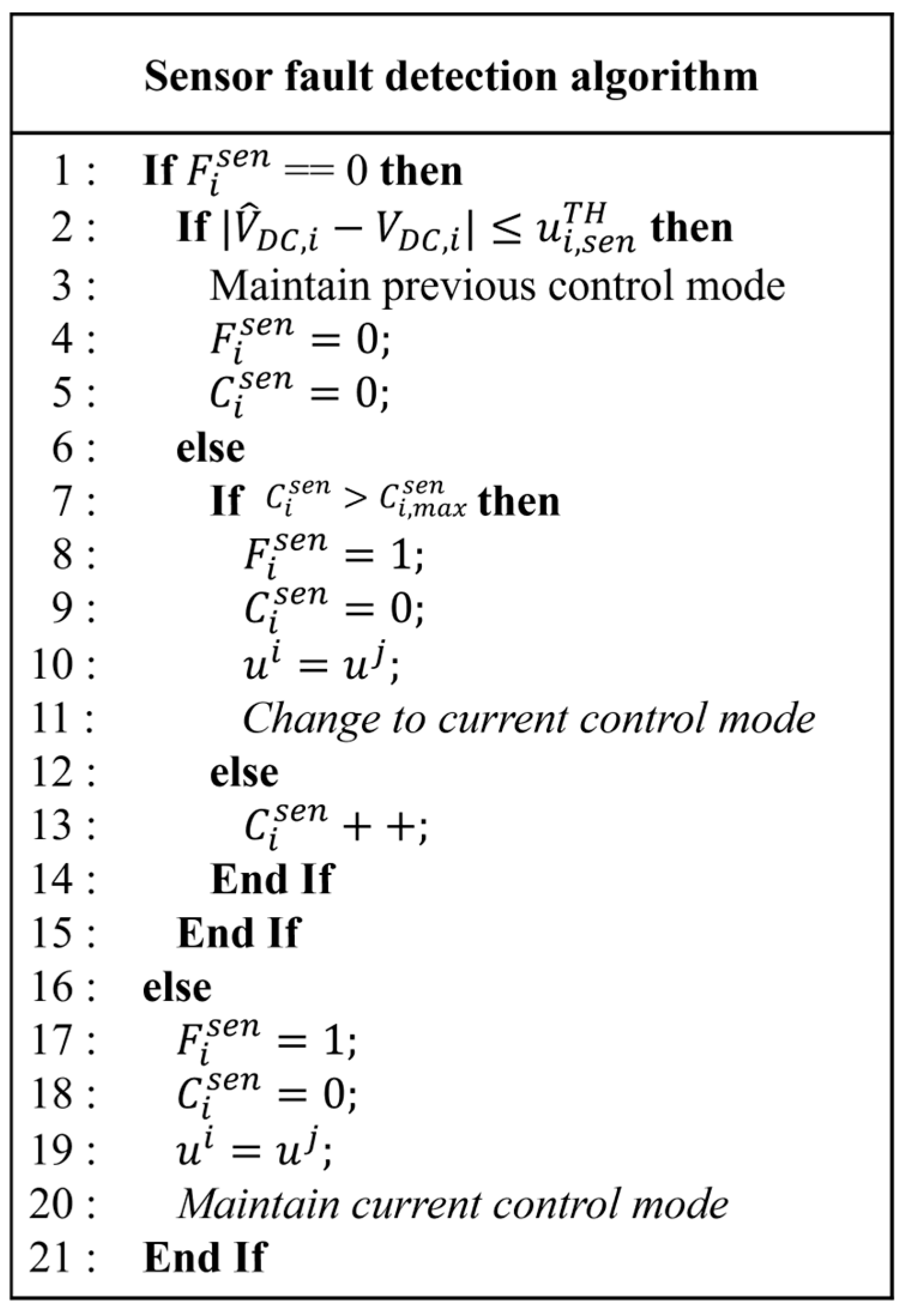
3.3. Detection of DCLV Sensor Failure and Hybrid Control Method

Figure 5 shows the detection algorithm of the DCLV sensor failure using the voltage observer to select the control modes of agent i in the proposed hybrid control. In Figure 5, the variables F i s e n , u i , s e n T H , C i s e n , and C i , m a x s e n denote the flag bit to indicate the DCLV sensor failure, the threshold value for the DCLV sensor failure detection algorithm, the counter value for the detection algorithm of the DCLV sensor failure, and the maximum value of the counter, respectively. If the power agent i has a DCLV sensor failure, flag bit F i s e n is set to one.
The estimated DCLV V ^ D C , i is obtained by the dynamic model of power agent as follows [30]:
V ^ ˙ D C , i = I i o u t C i V ^ D C , i C i R L i + N i V D C , i V ^ D C , i
where I i o u t , C i , R L i , and N i represent the converter output current of agent i, capacitance of agent i, virtual resistance of agent i, and observer gain, respectively. In order to improve the reliability of the system even in the presence of sensor faults, the DCLV sensor failure is identified by using estimated DCLV V ^ D C , i .
In the proposed DCLV sensor failure detection algorithm, when F i s e n is equal to zero, the detection algorithm compares the difference V ^ D C , i V D C , i with u i , s e n T H to detect the abnormality of the DCLV sensor. When V ^ D C , i V D C , i is smaller than u i , s e n T H , the detection algorithm recognizes that the sensor fault does not occur. Then, agent i maintains the previous control mode, and sets both F i s e n and C i s e n to zero. As the difference V ^ D C , i V D C , i becomes larger than u i , s e n T H , the proposed DCLV sensor failure detection algorithm compares C i s e n with C i , m a x s e n to detect the DCLV sensor failure. When the counter value C i s e n is larger than C i , m a x s e n , the detection algorithm confirms the occurrence of the DCLV sensor failure. Then, agent i changes control mode to the current control in which the current reference is set to that of the previous distributed control mode. In this case, the agent i sets F i s e n to one and C i s e n to zero. In addition, the secondary controller output in the power agent having the DCLV sensor failure, u i , is set to u j , which is received from the other power agent by the DCL. This is performed because the other power agents without the DCLV sensor failure should operate in distributed control even though the power agent i having the DCLV sensor failure operates in the current control mode. To achieve this, the power agent i having the DCLV sensor failure receives u j from the other power agent, and transmits this value to another power agent as shown in the DCL configuration of Figure 1.
When the counter value C i s e n is smaller than C i , m a x s e n , counter C i s e n is increased to count this event ( V ^ D C , i V D C , i > u i , s e n T H ) by maintaining the operation mode of agent i in the distributed control mode. By detecting the DCLV sensor failure accurately and changing DCMG operation to the appropriate mode under this condition, the proposed hybrid control scheme ensures a robust operation of the DCMG system.
The proposed detection algorithms such as the FDI attack detection based on the Lagrange extrapolation and the DCLV sensor failure detection based on the voltage observer can operate independently and reliably. The accuracy of the detection algorithm does not affect that of the other algorithm.
Although the proposed hybrid control strategy has robustness against both FDI attacks and sensor faults, it is weak to detect stealthy FDI attacks or slowly varying malicious data injection.

4. Simulation Results

The reliability and usefulness of the proposed hybrid control based on the detection algorithm for the FDI attack and the DCLV sensor failure are validated through comprehensive simulations for the DCMG system by using the PSIM 9.1.1.4 version software. The simulations consider various uncertain operating conditions, including FDI attacks, DCLV sensor failures, grid faults, minimum or maximum state-of-charge (SOC) levels of battery, and agent power fluctuations. The DCMG system parameters are summarized in Table 1.

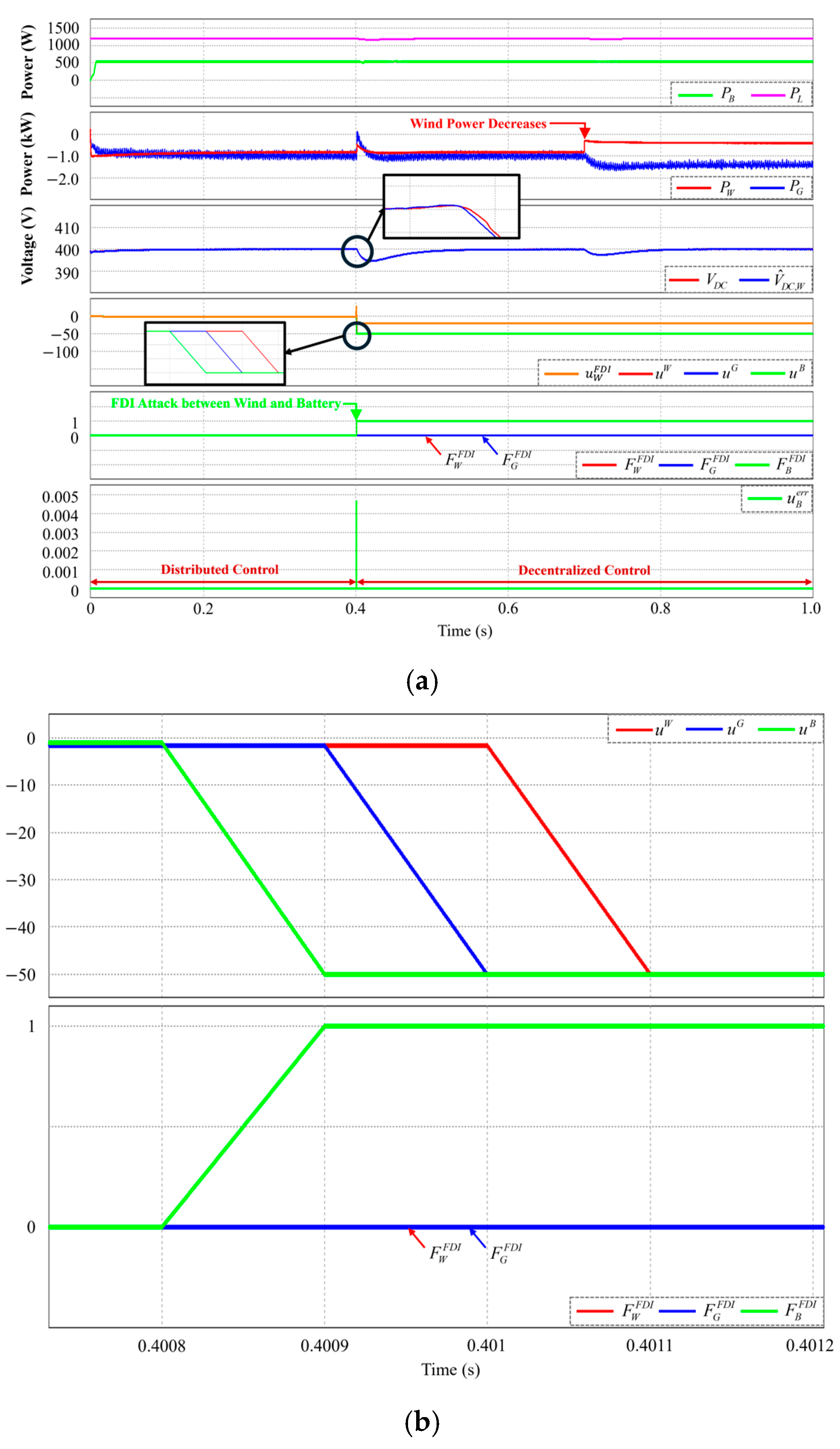
4.1. Power Variation in Wind Turbine Agent Under FDI Attack

Figure 6 depicts the simulation test results under the FDI attack in the DCL by which the wind turbine agent transmits the secondary controller output u W to the battery agent. In this simulation test, the wind power variation is also considered. In this figure, P i , V D C , V ^ D C , i , u i , F i F D I , and u e r r i denote the power of agent i, the actual value of DCLV, the estimated DCLV value of agent i, the secondary controller output of agent i, the flag bit of FDI attack in agent i, and the sum of squared errors between u k + p i and u ^ k + p i for the recent 10 samples which are defined in Section 3.2, respectively. In the fourth plot, u W F D I denotes the FDI attack in the DCL between the wind turbine and battery agents. In the beginning, the DCMG system operates in distributed control without an FDI attack or DCLV sensor fault. At t = 0.4 s, the FDI attack occurs in DCL between the wind turbine and battery agents. Due to the FDI attack, the value u e r r B increases and exceeds the threshold value u B , F D I T H . Then, the battery agent detects the FDI attack and sets its flag bit to one by the proposed FDI attack detection algorithm.
Following the proposed hybrid control method, the battery agent replaces its secondary controller output with the specific value δ i which is used to inform that the DCL between the wind turbine and battery agents is affected by the FDI attack. This specific value δ i is propagated to the other power agents by the DCL structure as shown in Figure 1. According to the DCL structure, the value δ i is first transmitted to the grid agent, and then, it is delivered to the wind turbine agent. This is clearly shown in the fourth plot of Figure 6 in which the secondary controller output values are changed to δ i in sequence of u B ,   u G , and u W . After the power agents transmit the specific value δ i to adjacent agents, their operations are switched to the decentralized control mode to remove the influence of the FDI attack. The third plot of Figure 6 represents the DCLV regulation performance. By virtue of the proposed FDI attack detection and hybrid control scheme, the DCLV is stably restored to the nominal value even under an FDI attack.
At t = 0.7 s, a wind power variation occurs in the wind turbine agent. In this condition, the DCMG system still maintains voltage regulation and power balance with the decentralized control scheme. As a result, it can be validated through this simulation test that the proposed control can maintain DCLV regulation and power balance even under an FDI attack and wind power variation owing to an effective FDI attack detection based on the Lagrange extrapolation and the use of a hybrid control method.
It is worth mentioning that the proposed FDI attack detection algorithm has a similar structure to the study [32] which uses the third-order Lagrange extrapolation based on 10 samples of square error to detect the FDI of the DCMG system. However, the study [32] does not consider the FDI attack in the DCLs as in this study. In addition, the sensor failure which normally affects the detection algorithm accuracy is also not considered. The proposed FDI attack detection and the method in [32] exhibit equivalent performance in terms of accuracy and computational efficiency. Both approaches effectively detect the FDI attacks and achieve zero steady-state error. Additionally, since both methods utilize 10 samples for computation, the computational efficiency remains the same. However, in terms of real-time applicability, the proposed method has the advantage since it can achieve the mode transition within 1.1 ms, whereas the method in [32] takes 9–20 ms for mode transition as reported.

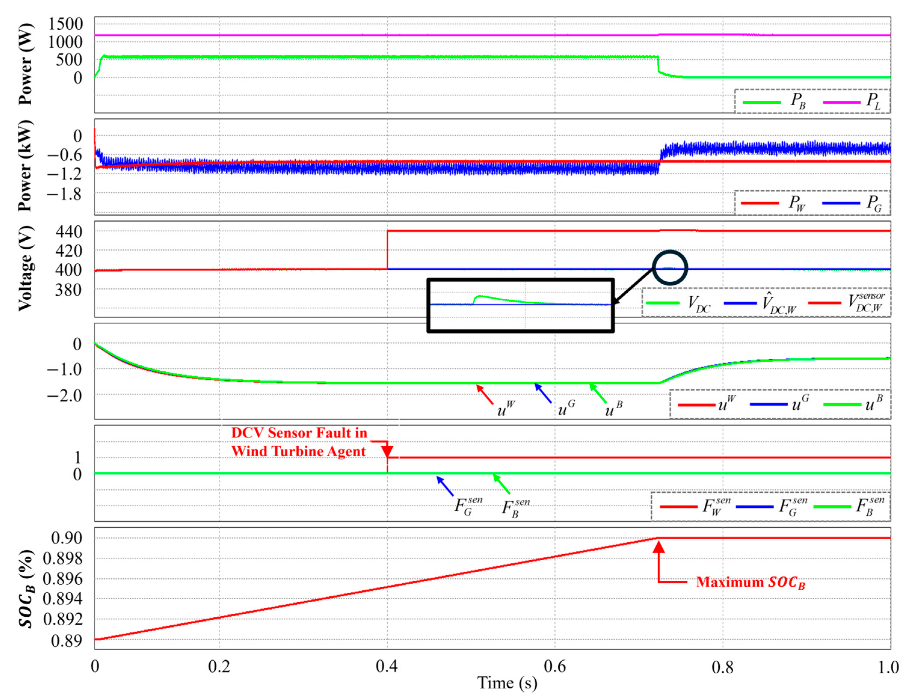
4.2. Case of Maximum Battery SOC Level Under DCLV Sensor Failure

Figure 7 shows the simulation results under a DCLV sensor failure in the wind turbine agent when the battery SOC level reaches the maximum value. In this figure, V D C , i s e n s o r , S O C B , and F i s e n denote the measured DCLV by the sensor in agent i, SOC level of the battery agent, and the flag bit to indicate the DCLV sensor failure, respectively. Initially, the DCMG system operates in distributed control without any FDI attack or sensor fault. It is also assumed that the wind turbine agent has a DCLV sensor failure at t = 0.4 s.
As soon as the DCLV sensor failure occurs, the wind turbine agent effectively detects DCLV sensor failure by the proposed sensor fault detection algorithm based on voltage observer and sets the flag bit F W s e n to one. Then, the wind turbine agent operation is shifted to the current control. At the same time, the secondary controller output of the wind turbine agent u W is replaced with that from the grid u G , which is transmitted to the battery agent according to the DCL structure of Figure 1.
By using this scheme, even though the wind turbine agent operation is changed to the current control, the other power agents (the grid agent and battery agent) can still operate in distributed control without changing operation modes. In addition, the power of the wind turbine is maintained at the same level before the sensor fault instant. Moreover, the third plot of Figure 7 clearly shows that the DCLV regulation is achieved stably in the presence of the DCLV sensor failure.
As the battery SOC level reaches its maximum level at t = 0.7 s, the battery agent is not able to operate in distributed control. Even in this condition, the grid agent effectively adjusts the power by using the proposed hybrid control. This test obviously demonstrates that the DCMG system continuously regulates the DCLV and maintains the power balance even under the maximum battery SOC level and DCLV sensor failure in the wind turbine agent.

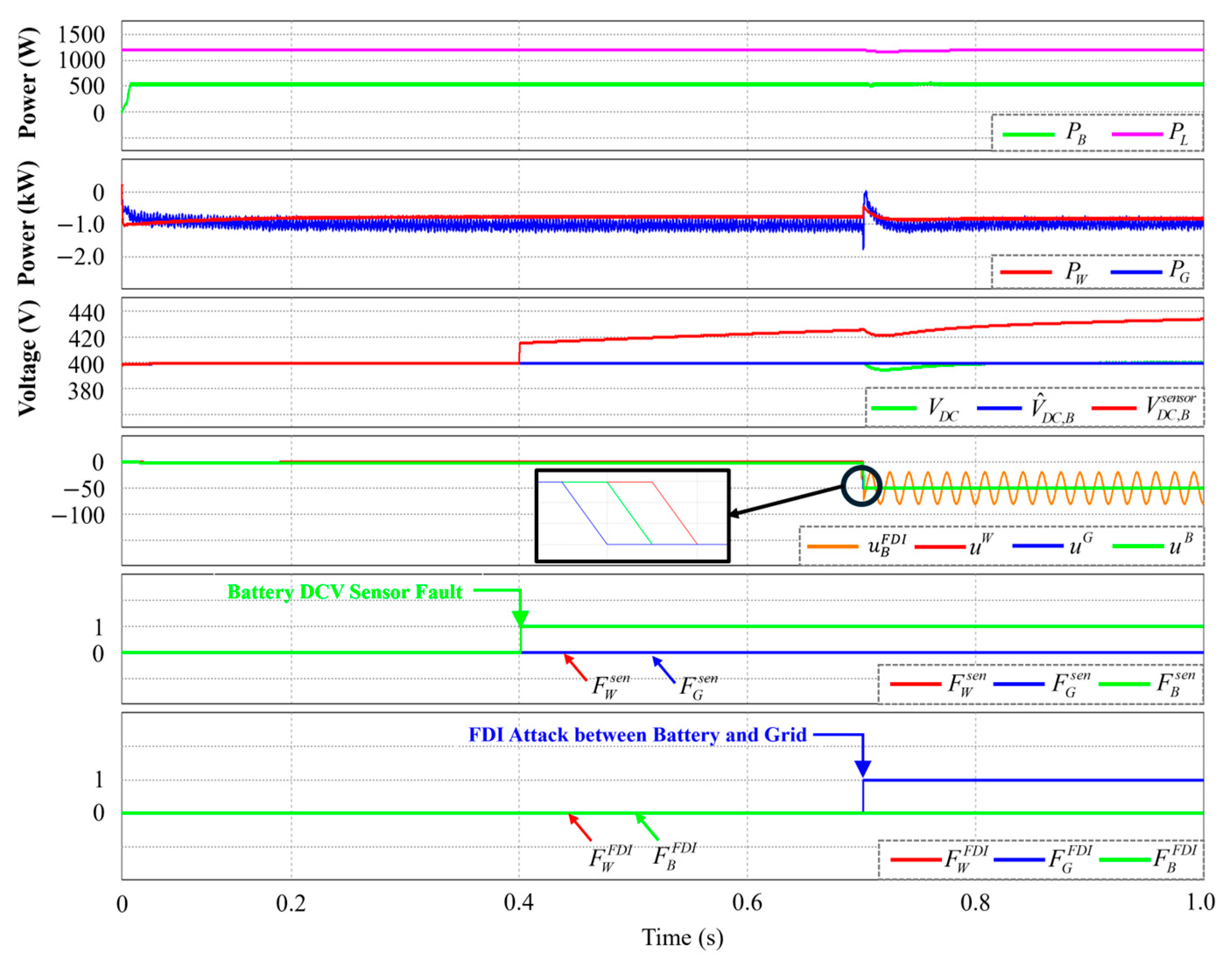
4.3. Case of DCLV Sensor Failure and FDI Attack

Figure 8 shows the simulation results under a DCLV sensor failure in the battery agent as well as an FDI attack in the DCL between the battery and grid agents. In the fourth plot, u B F D I denotes the FDI attack in the DCL between the battery and grid agents. The DCMG initially starts in distributed control without an FDI attack or sensor fault. At t = 0.4 s, the battery agent has a DCLV sensor failure. Using the proposed sensor fault detection algorithm based on the voltage observer, the battery agent effectively identifies this fault. After that, the battery agent transits the operation to the current control. At the same time, the secondary controller output of the battery agent u B is replaced with u W which is received from the wind turbine agent. By using this scheme, the grid and wind turbine agents still work in distributed control without changing the operation modes, even though the battery agent operation changed to the current control mode. Also, it is shown in the third plot of Figure 8 that the DCLV measurement by a sensor in the battery agent, V D C , B s e n s o r , has different and inaccurate values due to a sensor fault. However, in spite of this sensor fault, waveforms of the estimated and real DCLV values coincide well, which proves a reliable DCLV regulation performance of the proposed scheme.
At t = 0.7 s, the FDI attack occurs in the DCL between the battery and grid agents. Due to the FDI attack, the value u e r r G increases and exceeds the threshold value u G , F D I T H . Then, the grid agent detects the FDI attack and sets its flag bit F G F D I to one by the proposed detection algorithm of FDI attack. According to the proposed hybrid control method, the grid agent replaces its secondary controller output with the specific value δ i which is used to inform that the DCL between the battery and grid agents is affected by the FDI attack. This value δ i is propagated to the other power agents by the DCL structure as shown in Figure 1, in which δ i is first transmitted to the wind turbine agent, and then, it is transmitted to the battery agent. The fourth plot of Figure 8 clearly shows that the secondary controller output values are changed to δ i in sequence of u G ,   u W , and u B .
Since the battery agent was already changed to the current control mode at t = 0.4 s due to the DCLV sensor failure, only the grid and wind turbine power agents are switched to the decentralized control mode to remove the influence of the FDI attack. The third plot of Figure 8 represents the DCLV regulation performance. Even under both the DCLV sensor failure and FDI attack, the proposed hybrid control scheme stably regulates the DCLV to the nominal value and achieves effective power management. This simulation highlights the robustness of the proposed control and demonstrates the ability to maintain the system’s reliability and stability.

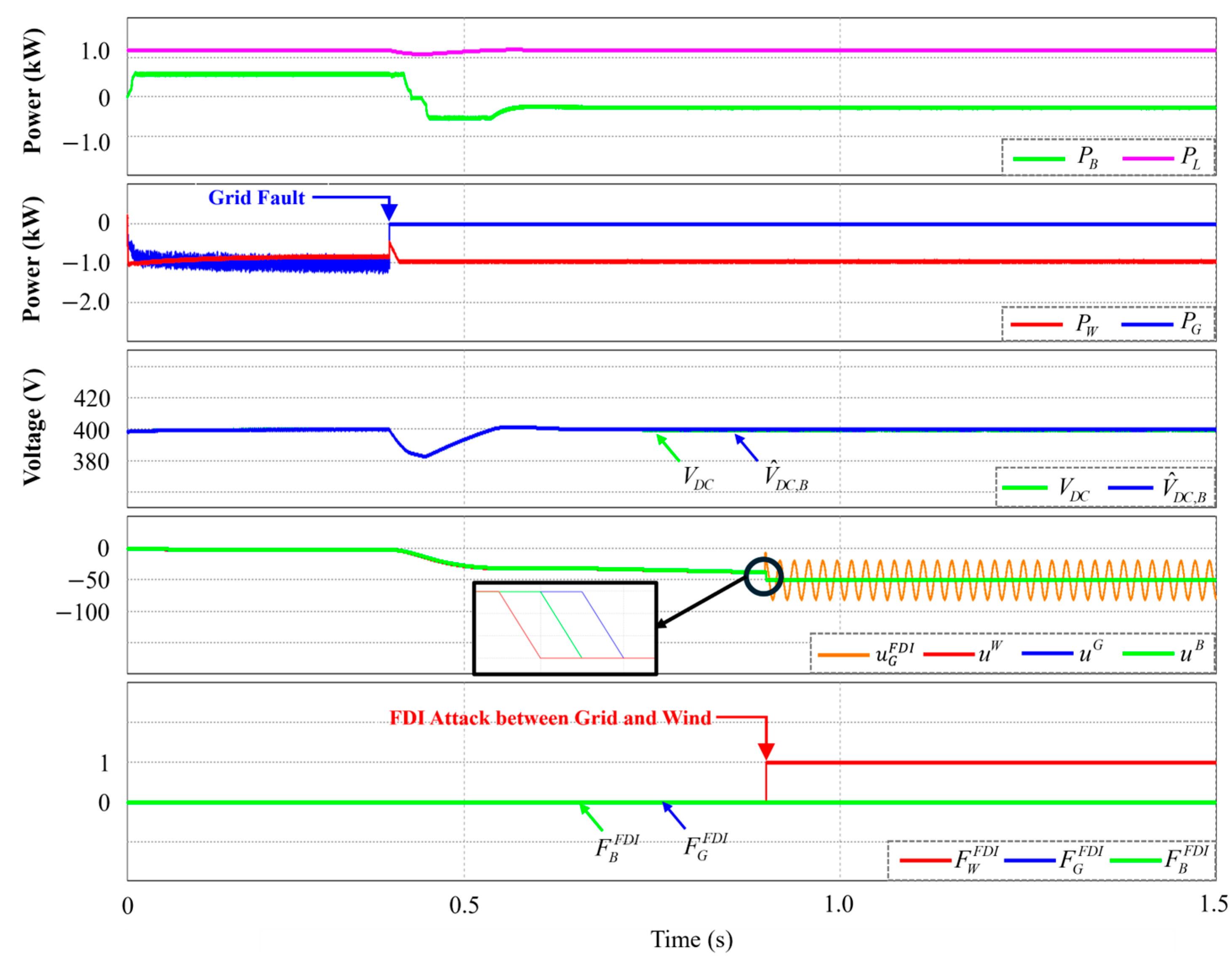
4.4. Mode Transition Under FDI Attack

Figure 9 shows the test results for the transition from grid-connected mode to islanded mode under an FDI attack in the DCL between the grid and wind turbine agents. In the fourth plot, u G F D I denotes the FDI attack in the DCL between the grid and wind turbine agents. Initially, the DCMG system works in distributed control without an FDI attack or sensor failure in DCLV. At t = 0.4 s, the DCMG system operating in distributed control is shifted from the grid-connected mode to islanded mode.
At t = 0.9 s, an FDI attack occurs in the DCL between the grid and wind turbine agents. The wind turbine agent detects the FDI attack and sets its flag bit F W F D I to one with the proposed FDI attack detection algorithm. Following the proposed hybrid control method, the wind turbine agent replaces its secondary controller output u W to δ i which informs the existence of the FDI attack in the DCL between the grid and wind turbine agents. The DCL first transmits δ i to the battery agent, and then to the grid agent. This is clearly observed in the fourth plot of Figure 9 in which the secondary controller output values are changed to δ i in sequence of u W ,   u B , and u G . After all the power agents transmit δ i to the adjacent agents, their operations are switched to the decentralized control mode to eliminate the negative influence caused by FDI attacks. The DCLV regulation performance in the third plot of Figure 9 clearly validates the usefulness of the FDI attack detection and hybrid control scheme.

4.5. Simultaneous FDI Attack and DCLV Sensor Fault

To prove that the FDI attack detection and the sensor fault detection algorithms operate independently in the proposed scheme even when they occur simultaneously, Figure 10 shows the simulation tests for simultaneous FDI attacks in the DCL between the grid and wind turbine agents, and DCLV sensor failure in the battery agent. In this test, the proposed detection algorithms can identify both the FDI attack and sensor fault even when they occur simultaneously at t = 0.4 s. Since the mode change due to the sensor fault has priority, the battery agent first switches to the current control mode due to the sensor failure. After that, the remaining power agents change the operation into the decentralized mode caused by the FDI attack. This simulation test clearly validates that the proposed FDI attack and sensor fault detection algorithms work properly even when both the FDI attack and sensor fault occur simultaneously.

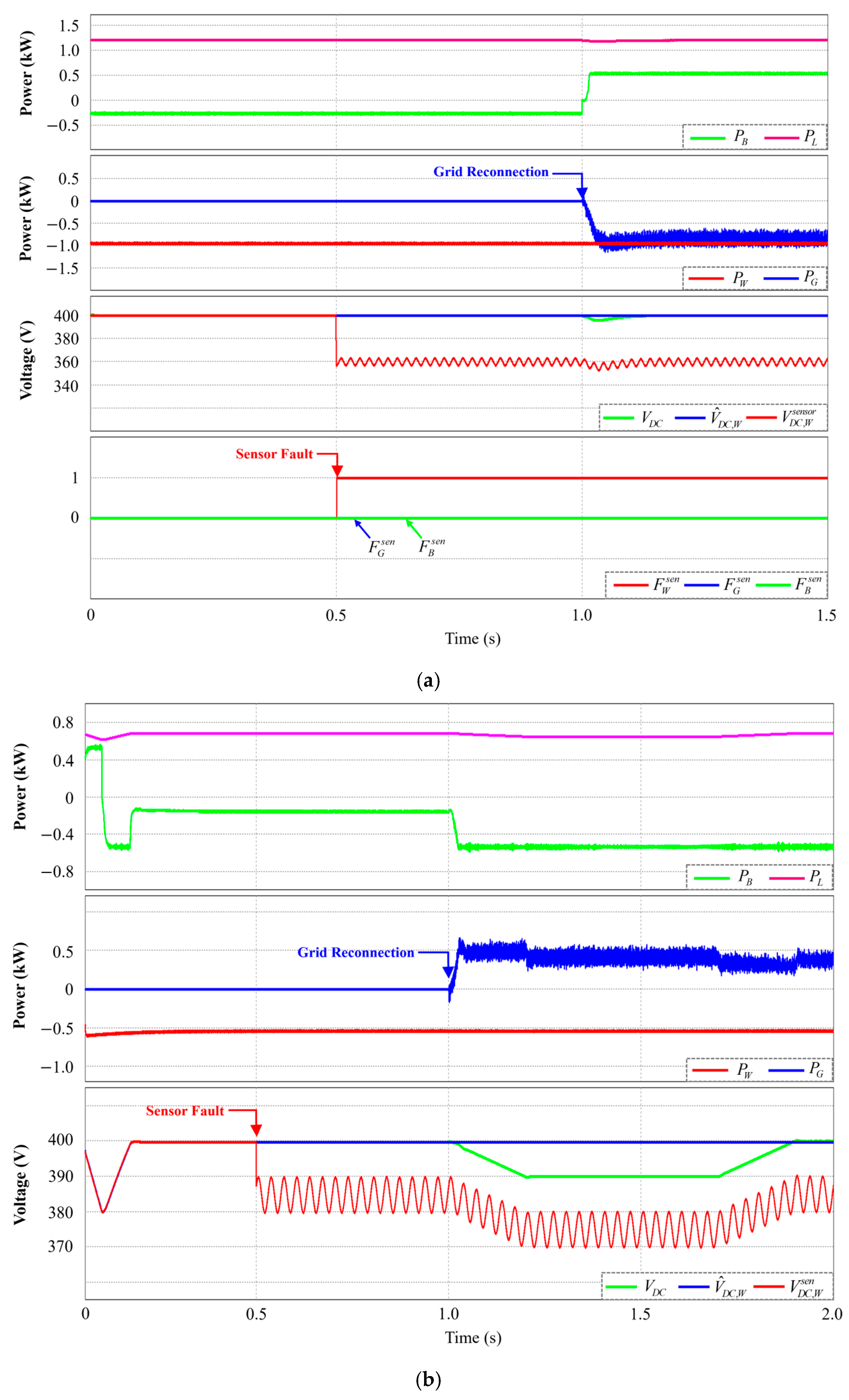
4.6. Grid Reconnection Under DCLV Sensor Failure

Figure 11a shows the test results for grid reconnection under sensor failure in the DCLV of the wind turbine agent. The DCMG system operates in the islanded mode with distributed control at the start. At t = 0.5 s, a sensor failure of DCLV occurs in the wind turbine agent. The wind turbine agent effectively detects this fault by using the proposed detection scheme based on the voltage observer. Then, the wind turbine agent transits the operation to the current control. At the same time, the secondary controller output of the wind turbine agent u W is replaced with u G which is received from the grid agent. Even though the wind turbine agent operation is changed to the current control, the battery agent still operates in distributed control without changing the operation mode.
Because of the sensor failure in the DCLV of the wind turbine agent, the DCLV measurement by the sensor in the wind turbine agent V D C , W s e n s o r has incorrect value as is shown in the third plot of Figure 11. Nevertheless, the proposed hybrid control strategy regulates well the DCLV to the nominal value. As the grid is reconnected at t = 1.0 s, the DCMG system operation is shifted from islanded mode to grid-connected mode. Even after the grid reconnection, the proposed hybrid control ensures a good power balance and DCLV regulation.
Figure 11b shows the simulation results of the control scheme in [30] for the transition from the islanded mode to the grid-connected mode under the DCLV sensor failure of the wind turbine agent. The simulation scenario of this test is exactly the same as in Figure 11a. It can be seen that when the grid reconnection happens at t = 1.0 s under the DCLV sensor failure of the wind turbine agent, the DCLV deviation is quite increased as compared to the proposed control scheme. It is confirmed from this comparison that the proposed scheme shows a smooth transient behavior for the operation mode change even under DCLV sensor failure, which significantly improves the reliability of the DCMG system.
Table 2 shows the comparison between the proposed scheme and conventional schemes. It can be seen from Table 2 that the proposed hybrid control scheme guarantees the stability of the DCMG system under both FDI attack and sensor fault while the previous control schemes in [26,27,28,30] only consider either an FDI attack or sensor fault.

5. Experimental Results

An experimental hardware setup, depicted in Figure 12, was utilized to evaluate the reliability and effectiveness of the proposed hybrid control. The hardware setup consisted of four power agents: wind turbine, battery, grid, and load agents with parameters given in Table 1. In all the power agents, a digital signal processor (DSP) TMS320F28335 was utilized to realize the proposed hybrid control scheme. The DSP TMS320F28335 performance parameters are shown in Table 3.
The experimental tests were performed by using the DSP-based hybrid control scheme and experimental hardware setup as shown in Figure 12 under various test conditions such as an FDI attack, a transition to islanded mode, and a DCLV sensor failure. The experiments were conducted in a controlled laboratory environment with a temperature maintained at approximately 20 °C. The relative humidity was kept at an appropriate level for standard laboratory conditions. The experimental equipment was operated under a stable power supply of 220 V, 60 Hz, ensuring a consistent performance without voltage fluctuations. Additionally, the laboratory environment was free from significant electromagnetic interference (EMI).

5.1. Islanded Mode Under FDI Attack

Figure 13 shows the experimental tests for the islanded mode under an FDI attack in the DCL between the wind turbine and battery agents. Figure 13a represents the experimental result without employing the proposed hybrid control. Initially, the DCMG operates in the islanded mode with distributed control. In this test, only the proposed FDI attack detection algorithm is used without the proposed hybrid control. When an FDI attack occurs in the DCL between the wind turbine and battery agents, the proposed algorithm effectively detects the FDI attack and sets the flag bit of the battery agent F B F D I to one. However, without using the proposed hybrid control, the DCMG system fails to maintain power balance and cannot regulate DCLV as clearly shown in DCLV oscillations and deviation in Figure 13a.
Figure 13b shows the experimental result for the islanded mode under the same FDI attack when the proposed FDI attack detection algorithm and hybrid scheme are employed at the same time. The DCMG system also operates initially in the islanded mode with distributed control. When an FDI attack occurs in the DCL between the wind turbine and battery agents, the battery agent effectively detects it by using the proposed FDI attack detection algorithm. Furthermore, due to the proposed hybrid scheme, the operation of the battery and wind turbine agents can be changed to the decentralized control mode, which successfully eliminates the negative effect of FDI attacks in the DCMG system. Consequently, the power balance and DCLV regulation can be achieved by the proposed strategy even under FDI attacks.
This experimental test highlights the effectiveness of both the proposed FDI attack detection and hybrid control schemes in ensuring the system stability and reliability under FDI attacks in the islanded mode.

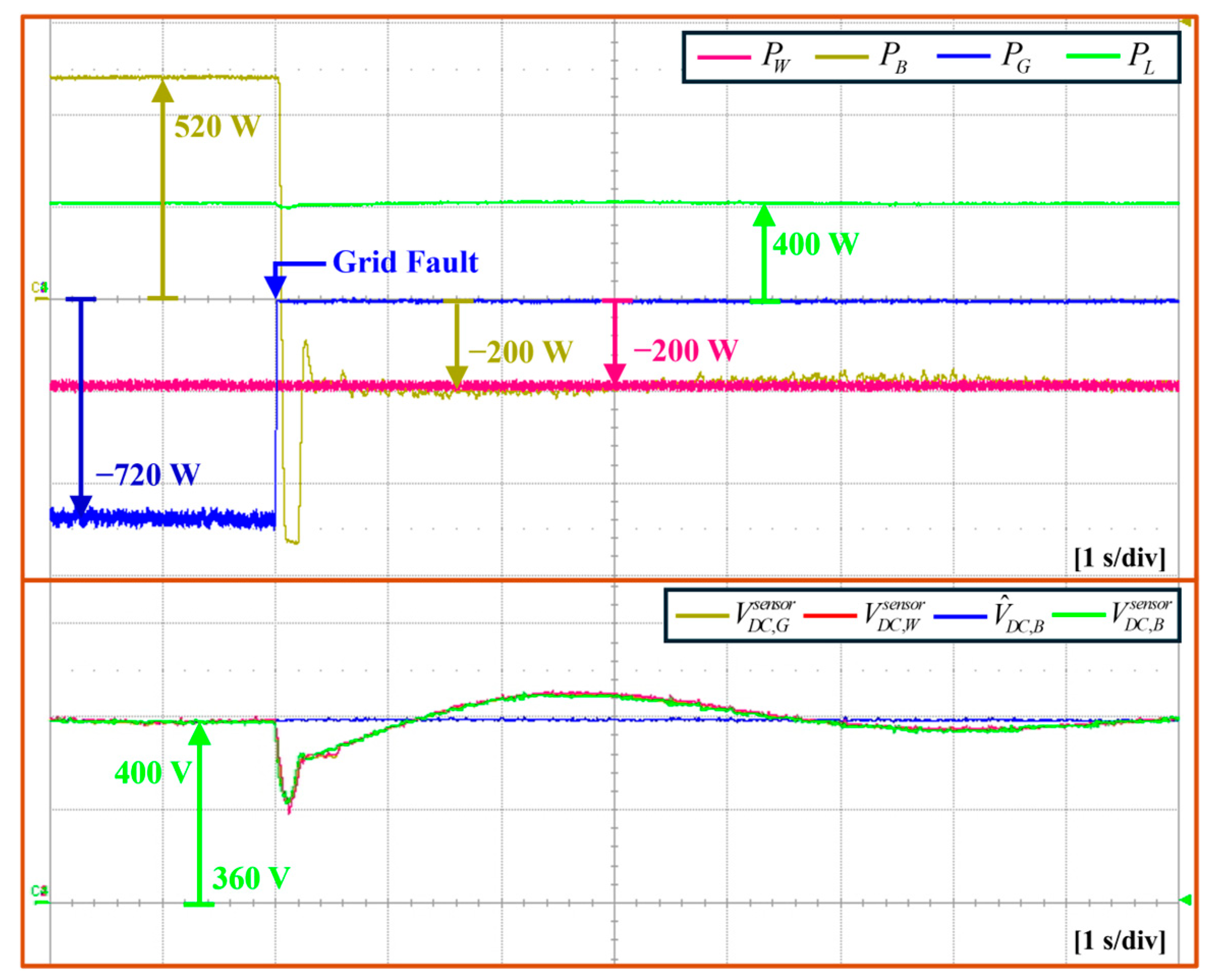
5.2. Transition from Grid-Connected Mode to Islanded Mode

Figure 14 shows the experimental result for the transition from the grid-connected mode to the islanded mode. In this test, the DCMG initially operates in the grid-connected mode with distributed control. When a grid fault occurs, the DCMG operation is changed to the islanded mode. Despite the grid disconnection and operation shift, the DCMG system stably maintains the distributed control by regulating the DCLV and ensuring the power balance during mode transition.

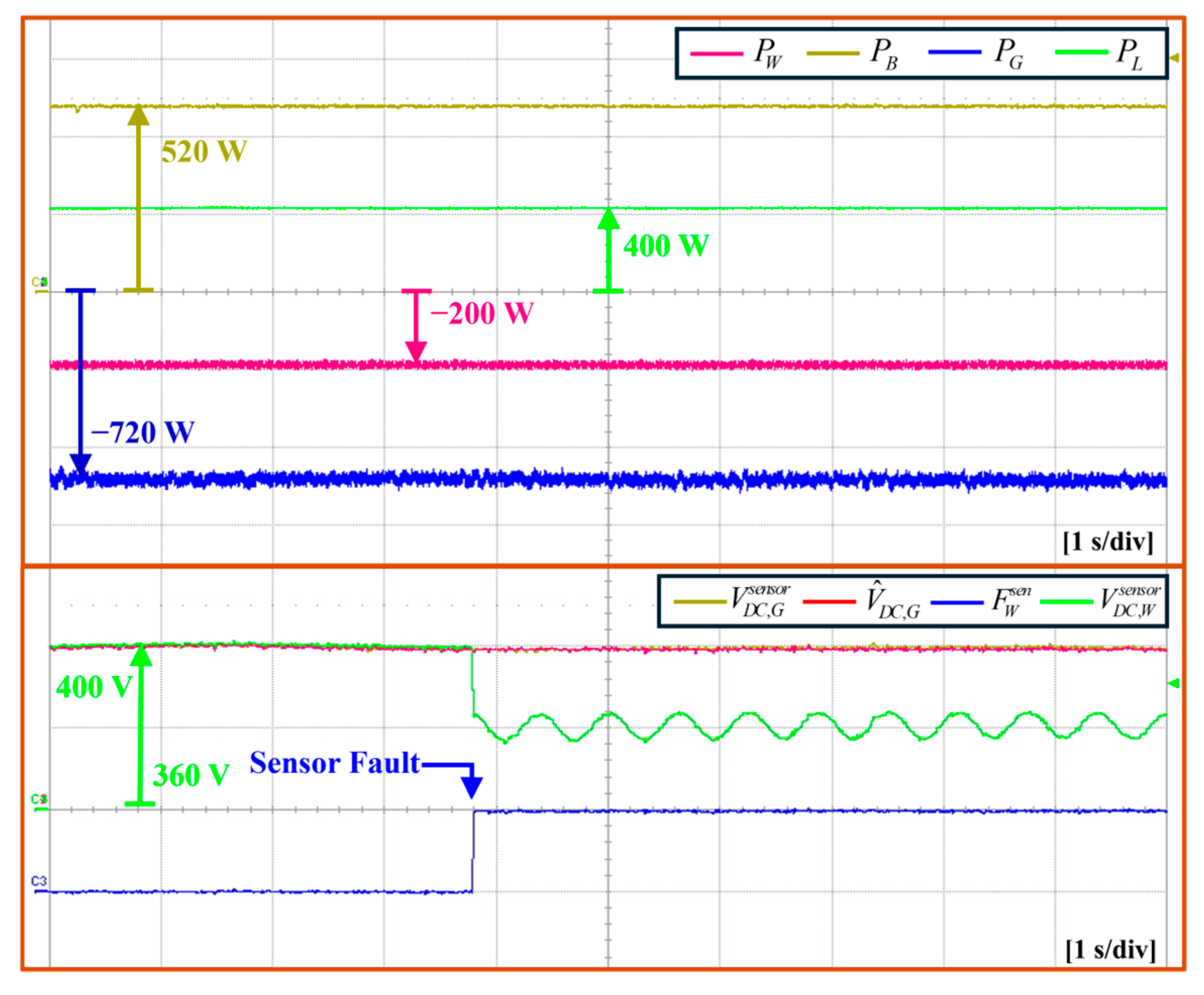
5.3. Grid-Connected Mode Under DCLV Sensor Failure

Figure 15 shows the experimental test of the proposed hybrid control for the grid-connected mode under a sensor failure in the DCLV of the wind turbine agent. Initially, the DCMG operates in the grid-connected mode with distributed control. When a DCLV sensor failure occurs in the wind turbine agent, it can be correctly detected by the proposed DCLV sensor failure detection algorithm based on the voltage observer. Then, the flag bit F W s e n is set to one. According to the proposed hybrid control strategy, the wind turbine agent shifts the operation to the current control. At the same time, the secondary controller output u W is set to u G to continuously maintain the operation of the other power agents even in this condition, which is also demonstrated in the simulation result in Figure 7. As a result, even though the DCLV measured by the sensor in the wind turbine agent V D C , W s e n s o r is not correct, the DCLV measured in the grid agent V D C , G s e n s o r coincides well with the estimated DCLV value V ^ D C , G and is effectively regulated to the nominal value. This experimental result also proves the effectiveness of the proposed hybrid control in sustaining the overall system operation.

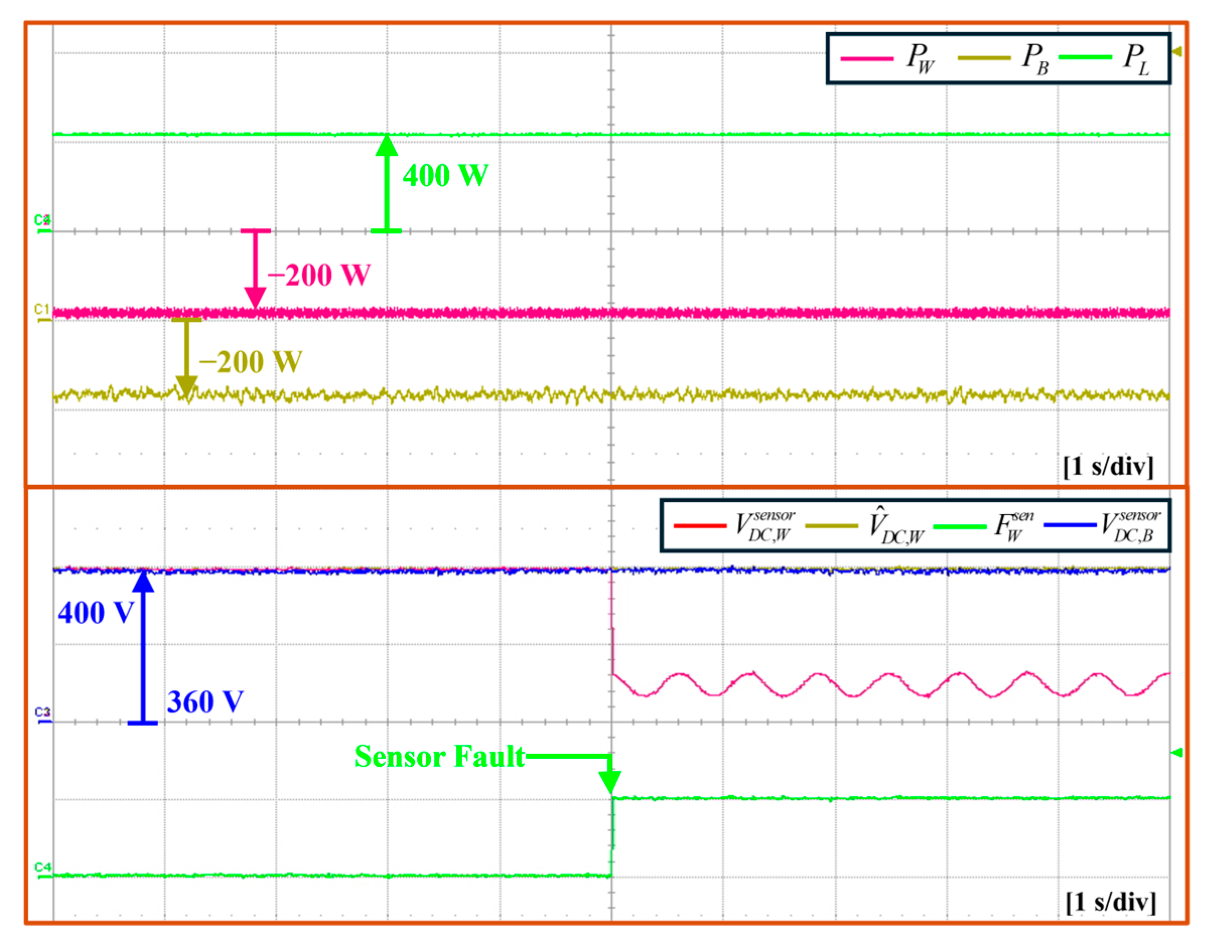
5.4. Islanded Mode Under DCLV Sensor Failure

Figure 16 shows the experimental test of the proposed hybrid control for the islanded mode under a sensor failure in the DCLV of the wind turbine agent. The DCMG starts in islanded mode with distributed control. When a DCLV sensor failure occurs in the wind turbine agent, the wind turbine agent detects it and sets F W s e n to one by using the proposed DCLV sensor failure detection algorithm. Then, the wind turbine agent operation is shifted to the current control, and the secondary controller output u W is set to u G . Even though the DCLV measured by the sensor in wind turbine agent V D C , W s e n s o r is not correct, the DCLV measured in the battery agent V D C , B s e n s o r is effectively regulated to the nominal value. This experimental test also demonstrates the usefulness of the proposed control under DCLV sensor failure in the islanded mode.

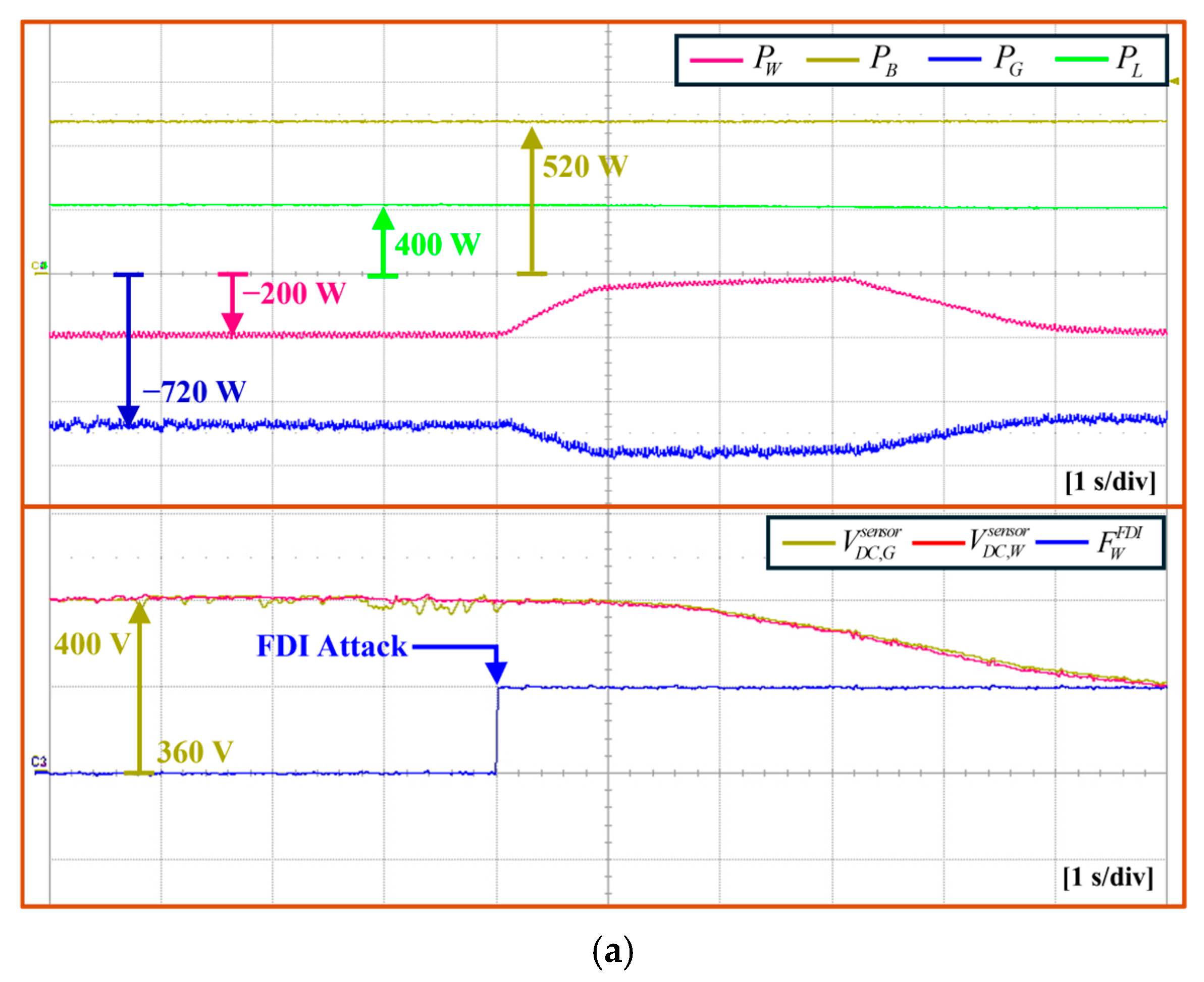
5.5. Gird-Connected Mode Under FDI Attack

Figure 17 shows the comparative experimental tests for the grid-connected mode under an FDI attack in the DCL between the grid and wind turbine agents. In Figure 17a, the proposed FDI attack detection algorithm is used without the proposed hybrid control scheme. The DCMG starts in the grid-connected mode with distributed control. When an FDI attack occurs in the DCL between the grid and wind turbine agents, the flag bit of the wind turbine agent F W F D I is set to one based on the proposed detection algorithm of FDI attack. However, without using the proposed hybrid control, the DCMG system fails to maintain power balance and cannot regulate DCLV as is observed in DCLV oscillations and deviation in Figure 17a. This degradation is caused by the absence of the proposed hybrid control.
Figure 17b shows the experimental result for the grid-connected mode under the same FDI attack when the proposed FDI attack detection algorithm and hybrid scheme are employed at the same time. In this figure, u G F D I denotes the secondary controller output of the grid agent affected by the FDI attack. The DCMG system also operates initially in the grid-connected mode with distributed control. When an FDI attack occurs in the DCL between the grid and wind turbine agents, the wind turbine agent detects it by using the proposed FDI attack detection algorithm and sets F W F D I to one. According to the proposed hybrid control, the wind turbine agent replaces its secondary controller output to the specific value δ i which is used to inform that the DCL between the grid and wind turbine agents is affected by the FDI attack. This value δ i is transmitted to the other power agents by the DCL structure as shown in Figure 1. According to the DCL structure, the value δ i is first transmitted to the battery agent and subsequently to the grid agent. This process is clearly shown in the bottom of Figure 17b in which the secondary controller output values are changed to δ i in sequence of u W ,   u B , and u G . After the power agents transmit the value δ i to adjacent agents, their operations are shifted to the decentralized control mode to remove the influence of the FDI attack. Due to the proposed FDI attack detection algorithm and hybrid control, the DCLV can be stably controlled to the nominal value even under FDI attacks.
These comparative experimental results highlight the effectiveness of the proposed hybrid control in ensuring system stability and reliability under FDI attacks in the grid-connected mode.

6. Conclusions

This study has proposed a hybrid control strategy for a DCMG based on the Lagrange extrapolation and voltage observer to enhance the system reliability under both FDI attacks and DCLV sensor failures. The key innovations and contributions of this study are summarized as follows:
Firstly, the proposed detection algorithm effectively identifies both sensor faults and FDI attacks independently and simultaneously without affecting the detection accuracy of each other. While third-order Lagrange extrapolation is utilized to identify FDI attacks in DCLs, a voltage observer is employed to monitor the abnormalities in the DCLV sensors. The proposed approach is simple and precise without mutual interference which degrades the accuracy of other detection algorithms. As a result, the DCMG system reliability is significantly improved under potential system disruptions.
Secondly, a hybrid control strategy that integrates the decentralized and distributed control methods has been proposed to achieve both power management and voltage stabilization for the DCMG system under abnormalities. In particular, as soon as FDI attacks are detected, the power agent operation is changed to the decentralized control mode to eliminate the false data by the attackers through DCLs. On the other hand, when the voltage sensor fault occurs in a power agent, the corresponding power agent shifts the operation to the current control mode to prevent DCMG system disruptions. This hybrid approach enables the DCMG system to operate continuously even under such emergency conditions by properly changing the operation modes of the power agents.
Finally, the feasibility and reliability of the proposed hybrid control strategy are demonstrated by various simulations and experimental tests under both FDI attacks in DCLs and DCLV sensor failures. These test results clearly confirm that the proposed scheme effectively maintains the voltage regulation and power balance in the presence of FDI cyber attacks and sensor faults.
Although the proposed hybrid control strategy has demonstrated robustness against both FDI attacks and sensor faults, there still exist several promising future studies. One of the promising studies is the enhancement of the detection algorithms to handle more complex attack scenarios, such as various coordinated cyber attacks targeting multiple nodes in the DCMG system, stealthy FDI attacks, or slowly varying malicious data injections. Additionally, integrating machine learning to detect complex attacks could further improve the adaptability and accuracy of fault identification. Moreover, the experimental validation in larger-scale DC microgrid systems with diverse renewable energy sources would provide deeper insights into the real-world applicability of the proposed approach.

Author Contributions

The overall concept, system design, and control structure for the DC microgrid was accomplished by S.-B.J., D.T.T., H.X.N., M.K. and K.-H.K. The research process, including programming and numerical data analysis, was carried out by S.-B.J., D.T.T. and H.X.N. under the supervision of K.-H.K. The manuscript was collaboratively prepared by S.-B.J., D.T.T., H.X.N., M.K. and K.-H.K. All authors have read and agreed to the published version of the manuscript.

Funding

This research was supported by the Basic Science Research Program through the National Research Foundation of Korea (NRF) funded by the Ministry of Education (NRF-2019R1A6A1A03032119).

Data Availability Statement

Data are contained within the article.

Acknowledgments

This study has been conducted with the support of the Korea Institute of Industrial Technology as “Development of core technologies of AI based self-power generation and charging for next-generation mobility” (KITECH EH-24-0003). This research was supported by the Basic Science Research Program through the National Research Foundation of Korea (NRF) funded by the Ministry of Education (NRF-2019R1A6A1A03032119).

Conflicts of Interest

The authors declare no conflicts of interest.

References

  1. Qazi, A.; Hussain, F.; Rahim, N.A.; Hardaker, G.; Alghazzawi, D.; Shaban, K.; Haruna, K. Towards sustainable energy: A systematic review of renewable energy sources, technologies, and public opinions. IEEE Access 2019, 7, 63837–63851. [Google Scholar] [CrossRef]
  2. Ahlgren, W.L. The dual-fuel strategy: An energy transition plan. Proc. IEEE 2012, 100, 3001–3052. [Google Scholar] [CrossRef]
  3. Olivares, D.; Mehrizi-Sani, A.; Etemadi, A.; Canizares, C.; Iravani, R.; Kazerani, M.; Hajimiragha, A.; Gomis-Bellmunt, O.; Saeedifard, M.; Palma-Behnke, R.; et al. Trends in microgrid control. IEEE Trans. Smart Grid 2014, 5, 1905–1919. [Google Scholar] [CrossRef]
  4. Zhou, L.; Zhang, Y.; Lin, X.; Li, C.; Cai, Z.; Yang, P. Optimal sizing of PV and BESS for a smart household considering different price mechanisms. IEEE Access 2018, 6, 41050–41059. [Google Scholar] [CrossRef]
  5. Fan, Z.; Fan, B.; Liu, W. Distributed control of DC microgrids for optimal coordination of conventional and renewable generators. IEEE Trans. Smart Grid 2021, 12, 4607–4615. [Google Scholar] [CrossRef]
  6. Kumar, D.; Zare, F.; Ghosh, A. DC microgrid technology: System architectures, AC grid interfaces, grounding schemes, power quality, communication networks, applications, and standardizations aspects. IEEE Access 2017, 5, 12230–12256. [Google Scholar] [CrossRef]
  7. Keshavarzi, D.; Farjah, E.; Ghanbari, T. Hybrid DC circuit breaker and fault current limiter with optional interruption capability. IEEE Trans. Power Electron. 2018, 33, 2330–2338. [Google Scholar] [CrossRef]
  8. Lotfi, H.; Khodaei, A. AC versus DC microgrid planning. IEEE Trans. Smart Grid 2017, 8, 296–304. [Google Scholar] [CrossRef]
  9. Hossain, M.I.; Hamanah, W.M.; Alam, M.S.; Shafiullah, M.; Abido, M.A. Fault ride through and intermittency improvement of renewable energy integrated MMC-HVDC system employing flywheel energy storage. IEEE Access 2023, 11, 50528–50546. [Google Scholar] [CrossRef]
  10. Al-Ismail, F.S. DC microgrid planning, operation, and control: A comprehensive review. IEEE Access 2021, 9, 36154–36172. [Google Scholar] [CrossRef]
  11. Abbasi, M.; Abbasi, E.; Li, L.; Aguilera, R.P.; Lu, D.; Wang, F. Review on the microgrid concept, structures, components, communication systems, and control methods. Energies 2023, 16, 484. [Google Scholar] [CrossRef]
  12. Mehdi, M.; Kim, C.-H.; Saad, M. Robust centralized control for DC islanded microgrid considering communication network delay. IEEE Access 2020, 8, 77765–77778. [Google Scholar] [CrossRef]
  13. Dragičević, T.; Lu, X.; Vasquez, J.C.; Guerrero, J.M. DC microgrids—Part I: A review of control strategies and stabilization techniques. IEEE Trans. Power Electron. 2016, 31, 4876–4891. [Google Scholar]
  14. Guo, F.; Xu, Q.; Wen, C.; Wang, L.; Wang, P. Distributed secondary control for power allocation and voltage restoration in islanded DC microgrids. IEEE Trans. Sustain. Energy 2019, 9, 1857–1869. [Google Scholar] [CrossRef]
  15. Anand, S.; Fernandes, B.G.; Guerrero, J. Distributed control to ensure proportional load sharing and improve voltage regulation in low-voltage DC microgrids. IEEE Trans. Power Electron. 2012, 28, 1900–1913. [Google Scholar] [CrossRef]
  16. Lu, X.; Guerrero, J.M.; Sun, K.; Vasquez, J.C. An improved droop control method for dc microgrids based on low bandwidth communication with dc bus voltage restoration and enhanced current sharing accuracy. IEEE Trans. Power Electron. 2014, 29, 1800–1812. [Google Scholar] [CrossRef]
  17. Huang, P.H.; Liu, P.C.; Xiao, W.; El Moursi, M.S. A novel droop-based average voltage sharing control strategy for DC microgrids. IEEE Trans. Smart Grid 2015, 6, 1096–1106. [Google Scholar] [CrossRef]
  18. Sahoo, S.K.; Sinha, A.K.; Kishore, N.K. Control techniques in AC, DC, and hybrid AC-DC microgrid: A review. IEEE J. Emerg. Sel. Top. Power Electron. 2018, 6, 738–759. [Google Scholar] [CrossRef]
  19. Yazdanian, M.; Mehrizi-Sani, A. Distributed control techniques in microgrids. IEEE Trans. Smart Grid 2014, 5, 2901–2909. [Google Scholar] [CrossRef]
  20. Sahoo, S.; Mishra, S. An adaptive event-triggered communication-based distributed secondary control for DC microgrids. IEEE Trans. Smart Grid 2018, 9, 6674–6683. [Google Scholar] [CrossRef]
  21. Gao, F.; Bozhko, S.; Asher, G.; Wheeler, P.; Patel, C. An improved voltage compensation approach in a droop-controlled DC power system for the more electric aircraft. IEEE Trans. Power Electron. 2016, 31, 7369–7383. [Google Scholar] [CrossRef]
  22. Dong, M.; Li, L.; Nie, Y.; Song, D.; Yang, J. Stability analysis of a novel distributed secondary control considering communication delay in DC microgrids. IEEE Trans. Smart Grid 2019, 10, 6690–6700. [Google Scholar] [CrossRef]
  23. Islam, S.; Agarwal, S.; Shyam, A.B.; Ingle, A.; Thomas, S.; Anand, S.; Sahoo, S.R. Ideal current-based distributed control to compensate line impedance in DC microgrid. IET Power Electron. 2018, 11, 1178–1186. [Google Scholar] [CrossRef]
  24. Sahoo, S.; Mishra, S.; Peng, C.H.; Dragicevic, T. A stealth cyber attack detection strategy for DC microgrids. IEEE Trans. Power Electron. 2019, 34, 8162–8174. [Google Scholar] [CrossRef]
  25. Liu, X.K.; Wen, C.; Xu, Q.; Wang, Y.W. Resilient control and analysis for DC microgrid system under DoS and impulsive FDI attacks. IEEE Trans. Smart Grid 2021, 12, 3742–3754. [Google Scholar] [CrossRef]
  26. Zhang, G.; Tong, D.; Chen, Q.; Zhou, W. Sliding mode control against false data injection attacks in DC microgrid systems. IEEE Syst. J. 2023, 17, 6159–6168. [Google Scholar] [CrossRef]
  27. Chandra, M.V.S.S.; Mohapatro, S. Hybrid sensor fault tolerant control of low voltage DC microgrid. IEEE Trans. Ind. Appl. 2024, 60, 1705–1715. [Google Scholar] [CrossRef]
  28. Vafamand, N.; Arefi, M.M.; Asemani, M.H.; Javadi, M.S.; Wang, F.; Catalão, J.P. Dual-EKF-based fault-tolerant predictive control of nonlinear DC microgrids with actuator and sensor Faults. IEEE Trans. Ind. Appl. 2022, 58, 5438–5446. [Google Scholar] [CrossRef]
  29. Tan, S.; Xie, P.; Guerrero, J.M.; Vasquez, J.C.; Han, R. Cyberattack detection for converter-based distributed dc microgrids: Observer-based approaches. IEEE Ind. Electron. Mag. 2022, 16, 67–77. [Google Scholar] [CrossRef]
  30. Jo, S.-B.; Tran, D.T.; Jabbar, M.A.M.; Kim, M.; Kim, K.-H. Continuous power management of decentralized DC microgrid based on transitional operation modes under system uncertainty and sensor failure. Sustainability 2024, 16, 4925. [Google Scholar] [CrossRef]
  31. Liu, Y.; Wang, G.; Ye, Z. Dynamic mode extrapolation to improve the efficiency of dual time stepping method. J. Comput. Phys. 2018, 352, 190–212. [Google Scholar] [CrossRef]
  32. Madichetty, S.; Mishra, S. Cyber attack detection and correction mechanisms in a distributed DC microgrid. IEEE Trans. Power Electron. 2022, 37, 1476–1485. [Google Scholar]
Figure 1. System configuration of a DCMG.
Electronics 14 01087 g001
Figure 2. Proposed hybrid control structure of the DCMG system under FDI attack.
Electronics 14 01087 g002
Figure 3. Detection of FDI attack using the Lagrange extrapolation.
Electronics 14 01087 g003
Figure 4. Detection algorithm of FDI attack using the Lagrange extrapolation for control mode selection.
Electronics 14 01087 g004
Figure 5. Detection algorithm of DCLV sensor failure using the voltage observer for control mode selection.
Electronics 14 01087 g005
Figure 6. Simulation results under the FDI attack in the DCL between the wind turbine and battery agents with wind power variation. (a) Whole waveforms. (b) Enlarged view during the transition phase.
Electronics 14 01087 g006
Figure 7. Simulation results under sensor failure in DCLV of wind turbine agent with maximum SOC level of battery.
Electronics 14 01087 g007
Figure 8. Simulation results under the DCLV sensor failure in the battery agent as well as the FDI attack in the DCL between the battery and grid agents.
Electronics 14 01087 g008
Figure 9. Simulation results for the transition from the grid-connected mode to islanded mode under an FDI attack in the DCL between the grid and wind turbine agents.
Electronics 14 01087 g009
Figure 10. Simulation results for simultaneous FDI attacks in the DCL between the grid and wind turbine agents, and DCLV sensor failure in the battery agent.
Electronics 14 01087 g010
Figure 11. Comparative simulation for the transition from the islanded mode to the grid-connected mode under the DCLV sensor failure of the wind turbine agent. (a) Proposed control scheme. (b) Control scheme [30].
Electronics 14 01087 g011
Figure 12. Experimental hardware configuration of DCMG system.
Electronics 14 01087 g012
Figure 13. Experimental results for the islanded mode under the FDI attack in the DCL between the wind turbine and battery agents. (a) Without the proposed hybrid scheme. (b) With the proposed hybrid scheme.
Electronics 14 01087 g013
Figure 14. Experimental results of the distributed secondary control for the transition from the grid-connected mode to the islanded mode.
Electronics 14 01087 g014
Figure 15. Experimental results of the proposed hybrid control for the grid-connected mode under the sensor failure in the DCLV of the wind turbine agent.
Electronics 14 01087 g015
Figure 16. Experimental results of the proposed hybrid control for the islanded mode under the sensor failure in the DCLV of the wind turbine agent.
Electronics 14 01087 g016
Figure 17. Comparative experimental results for the grid-connected mode under FDI attack in the DCL between the grid and wind turbine agents. (a) Without the proposed hybrid control. (b) With the proposed hybrid control.
Electronics 14 01087 g017aElectronics 14 01087 g017b
Table 1. DCMG system parameters.
Power AgentsParametersValue
DC-linkNominal DCLV400 V
Capacitance4 mF
Grid agentTransformer Y/Δ380/220 V
Grid voltage220 V
Grid frequency60 Hz
Maximum absorbing power2000 W
Maximum supporting power−2000 W
Wind turbine agentPMSG number of poles6
PMSG inertia0.111 kgm2
PMSG flux linkage0.18 Wb
Converter filter inductance7 mH
Maximum power−1500 W
Battery agentMinimum level of SOC20%
Maximum level of SOC90%
Maximum voltage180 V
Rated capacity25 Ah
Limitation level of charging power540 W
Limitation level of discharging power−540 W
Maximum input voltage300 V
Maximum input current6 A
Maximum input power800 W
Load agentLoad 1200 W
Load 2200 W
Load 3200 W
Table 2. Comparison between proposed schemes and conventional schemes.
Distributed Control [26]Distributed Control [27,28]Decentralized Control [30]Proposed Scheme
FDI attackConsideredNot consideredNot consideredConsidered
Sensor faultNot consideredConsideredConsideredConsidered
Table 3. Performance parameters of DSM TMS320F28335.
Performance ParameterSpecification
Clock frequency150 MHz
Cycle time6.67 ns
Floating-point precisionIEEE 754 single precision
ADC resolution12-bit
Conversion rate80 ns
Disclaimer/Publisher’s Note: The statements, opinions and data contained in all publications are solely those of the individual author(s) and contributor(s) and not of MDPI and/or the editor(s). MDPI and/or the editor(s) disclaim responsibility for any injury to people or property resulting from any ideas, methods, instructions or products referred to in the content.

