Abstract
This paper presents an enhanced sensorless control strategy for permanent magnet synchronous motors (PMSMs) by improving back-electromotive force (back-EMF) estimation and control robustness. An improved back-EMF extended state observer (ESO) is proposed, incorporating back-EMF differentiation to compensate for DC position error without requiring an increased observer bandwidth. Furthermore, an ESO-based quadrature phase-locked loop (QPLL) is developed to improve position tracking accuracy and enhance the robustness of the speed loop sliding mode controller (SMC) against unknown disturbances. To address parameter uncertainties in the back-EMF observer and current controller, a recursive least squares (RLSs) algorithm with an adaptive forgetting factor is introduced, providing a balance between adaptation speed and noise suppression. Simulation results validate the proposed approach, demonstrating improved estimation accuracy, disturbance rejection, and overall robustness in sensorless PMSM control.
1. Introduction
Modern electric cars are increasingly widespread as advancements in power electronics continue to grow [1]. Among various motor options, the permanent magnet synchronous motor (PMSM) stands out in electric car applications due to its superior efficiency, power factor, power density, and torque density [2]. These advantages come from its design, which relies on permanent magnets, considered one of the most remarkable innovations in modern engineering, with much still to be explored [3]. The emergence of field-oriented control (FOC) has addressed one of the biggest challenges in PMSM control by simplifying its strong coupling issue, making it as easy to manage as a DC motor. However, PMSMs still face challenges, particularly parameter variations caused by external factors, such as high temperatures, which can also damage sensors, as they are essential components in the control system [4,5,6].
Accurate speed measurement is a key component in implementing FOC [7,8]. Traditionally, sensors are used to measure speed, but they add cost, weight, and are prone to failure under harsh conditions [9]. To address these challenges, researchers have introduced sensorless control techniques that operate solely on a simple mathematical model of the PMSM [10,11,12]. In sensorless control, estimating the back electromotive force (back-EMF) is crucial because it indirectly provides speed information [13,14]. However, since no back-EMF is generated at a standstill, this approach has traditionally been effective only in medium- to high-speed ranges [15]. In recent studies, various model-based back-EMF strategies have emerged to extend the operational range into low-speed conditions [15,16].
An observer-based approach is commonly employed for back-EMF estimation in sensorless PMSM control, relying on a mathematical model of the motor. However, model mismatches can degrade estimation accuracy, making robust observers a preferred solution [17,18]. Sliding mode observer (SMO) and extended state observer (ESO) are widely recognized for their ability to handle uncertainties and disturbances with relatively simple designs [18,19,20]. Despite their advantages, SMO suffers from chattering due to the discontinuous switching function, often necessitating additional filtering stages to obtain an accurate back-EMF estimate. In contrast, ESO inherently acts as a low-pass filter, eliminating the need for extra filtering [14,20]. However, its low-pass filtering characteristic can lead to DC position estimation errors when the observer bandwidth is insufficient. Simply increasing the bandwidth is not a straightforward solution, as excessive bandwidth can amplify noise sensitivity [21]. To address these limitations, various studies have focused on enhancing both SMO and ESO to improve back-EMF estimation accuracy while mitigating their respective drawbacks [22,23]. The work in [20] introduced a quasi-resonant controller with reduced order into the ESO structure to minimize DC offset estimation errors and reduce the phase lag in back-EMF estimation. While this method enhances estimation precision, it also increases computational complexity and requires tuning multiple parameters, challenges that are commonly observed across various proposed approaches, along with insufficient consideration of parameter uncertainties.
Once the back-EMF signal is estimated, the next challenge is accurately extracting the rotor position and speed from it. While the arctangent function can directly compute rotor position from the estimated back-EMF, and its derivative theoretically yields speed, these methods are highly sensitive to high-frequency noise, leading to inaccuracies in practical implementations [24]. To overcome this limitation, phase-locked loop (PLL) techniques have been widely adopted, as they inherently suppress noise by leveraging a PI controller to estimate speed, using integration to determine rotor position. This approach avoids the noise amplification associated with differentiation, resulting in smoother and more reliable estimates [25]. Recent advancements in PLL techniques, such as quadrature PLL (QPLL), along with ESO-based methods, have further improved speed and position estimation accuracy by effectively rejecting unknown disturbances and enabling higher precision [26,27].
This paper proposes several improvements to enhance sensorless control performance. The back-EMF ESO design is improved by incorporating the differentiation of the back-EMF, which compensates for the DC position error without requiring a higher observer bandwidth compared to conventional ESOs. A QPLL based on ESO is developed to improve position tracking accuracy and reinforce the sliding mode control (SMC) of the speed loop controller, leading to greater robustness and faster convergence against unknown disturbances. To further enhance robustness against parameter uncertainties in the back-EMF ESO and the current controller, a recursive least squares (RLSs) method with an adaptive forgetting factor based on an exponential function is introduced. These advancements lead to a more robust and reliable sensorless control system.
The discussion in this paper progresses as follows: Section 2 describes the PMSM model, incorporating parameter uncertainties to account for real-world variations. Section 3 presents the back-EMF observer design, comparing the conventional ESO with the proposed method. Section 4 explores the ESO-based QPLL approach for extracting speed and position estimates. Section 5 outlines the control strategies, where SMC regulates speed, and predictive current control manages current. Section 6 discusses parameter estimation using the RLS algorithm with an adaptive forgetting factor. Section 7 assesses the proposed sensorless control strategy through simulation results. Finally, Section 8 summarizes the key findings and contributions.
2. Model of PMSM
This paper considers a surface-mounted permanent magnet synchronous motor with equal d-axis and q-axis inductances. To simplify the analysis, magnetic saturation, eddy currents, and hysteresis losses are neglected. The PMSM with parameter uncertainties can be modeled in the -frame as follows:
where and denote the stator currents in the -frame, and and denote the corresponding stator voltages, represents the stator resistance, and represents the stator inductance; the torque constant is defined as , with being the number of pole pairs, the rotor permanent magnet flux linkage, J the moment of inertia, f the friction coefficient, the electrical angular velocity, and the load torque; additionally, , , and are introduced to account for parameter uncertainties in the PMSM model and are modeled as follows:
where and denote the deviations of the stator resistance and inductance from their nominal values, while and account for variations in the moment of inertia and friction coefficient from their assumed values.
3. Back-EMF Observer
The stationary frame model facilitates the extraction of the rotor’s electrical position via the back-EMF observer. In this frame, the current model is represented as:
where and represent the current and voltage along the -axis, and and represent the current and voltage along the -axis. The unknown signals in the model, denoted as and , are defined by:
where and correspond to the back-EMF in the -frame, defined as follows:
where represents the electrical position of the rotor, it is clear that the back-EMF in (4) is independent of the current and voltage states, thereby making the stationary frame an ideal option for estimating the back-EMF signals.
3.1. Conventional ESO
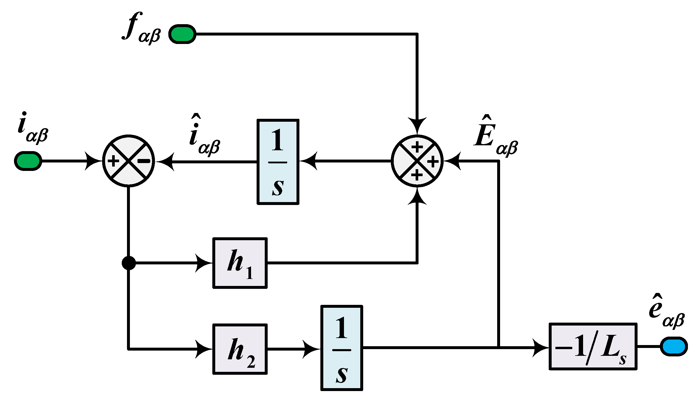
The ESO estimates the unknown signals and by defining them as system states, with its structure depicted in Figure 1 and detailed as follows:
where the subscript “” indicates that the equation applies identically to both the and axes due to their symmetrical structure, and the hat symbol “ ” denotes that the associated state variable is an estimate. Additionally, the gains and are defined as constant observer gains.
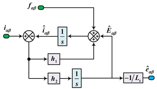
Figure 1.
Structural diagram of the conventional back-EMF ESO.
By applying the Laplace transform to (3) and (6), we obtain a transfer function that relates the estimated back-EMF to its actual value, as detailed below:
where s is defined as the Laplace operator.
As established by (7), the Routh–Hurwitz stability criterion requires and to be strictly positive. To satisfy these conditions, the observer bandwidth is chosen to be positive, ensuring the gains are parameterized as and .
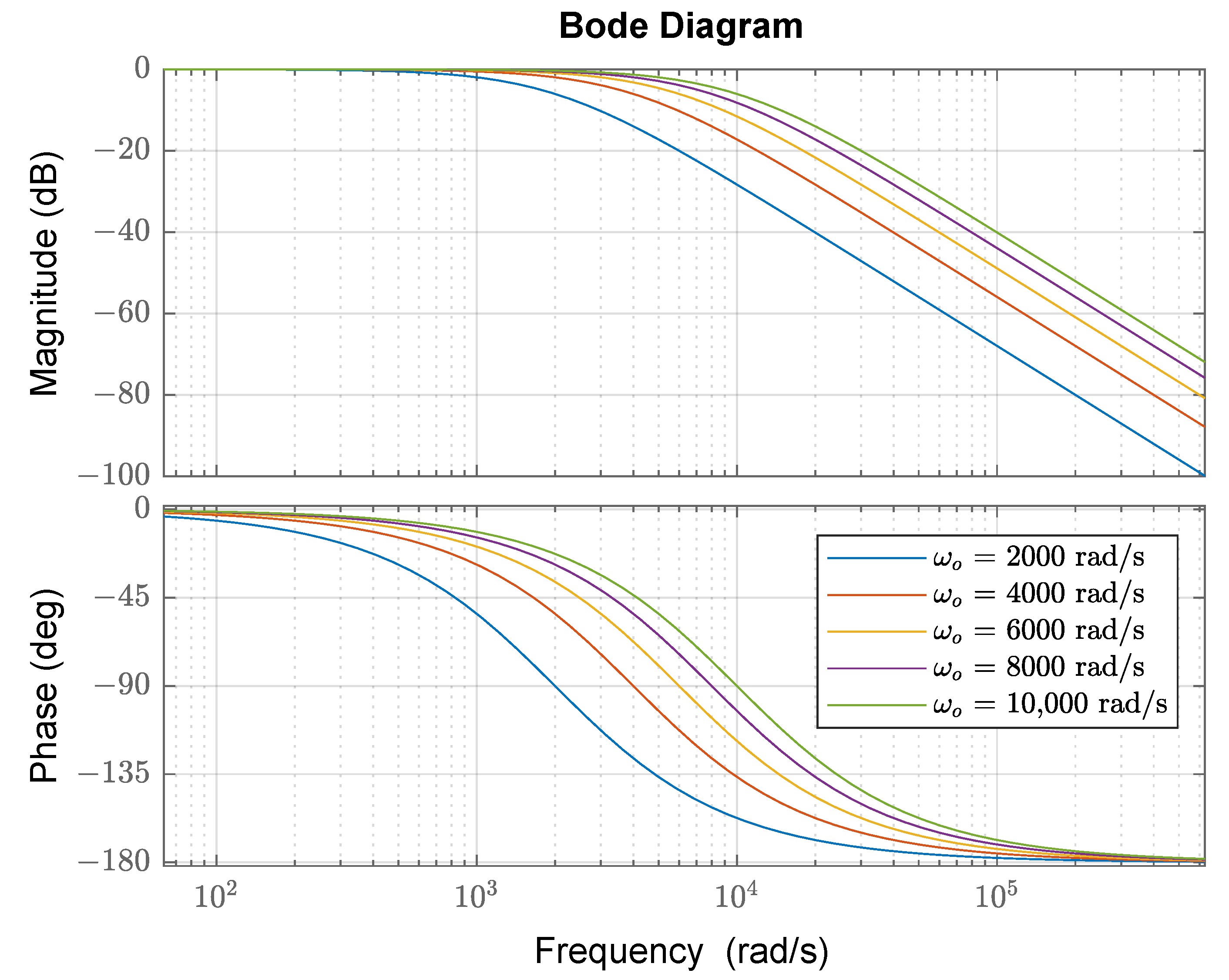
Figure 2 presents the frequency response of for different observer bandwidths, demonstrating its low-pass filtering behavior. A higher observer bandwidth () effectively reduces phase lag and amplitude attenuation, leading to a more accurate estimation of back-EMFs. However, this improvement increases the sensitivity of the observer to high-frequency noise, which may affect the robustness of the estimation.

Figure 2.
Bode diagram of the conventional back-EMF ESO.
3.2. Proposed ESO
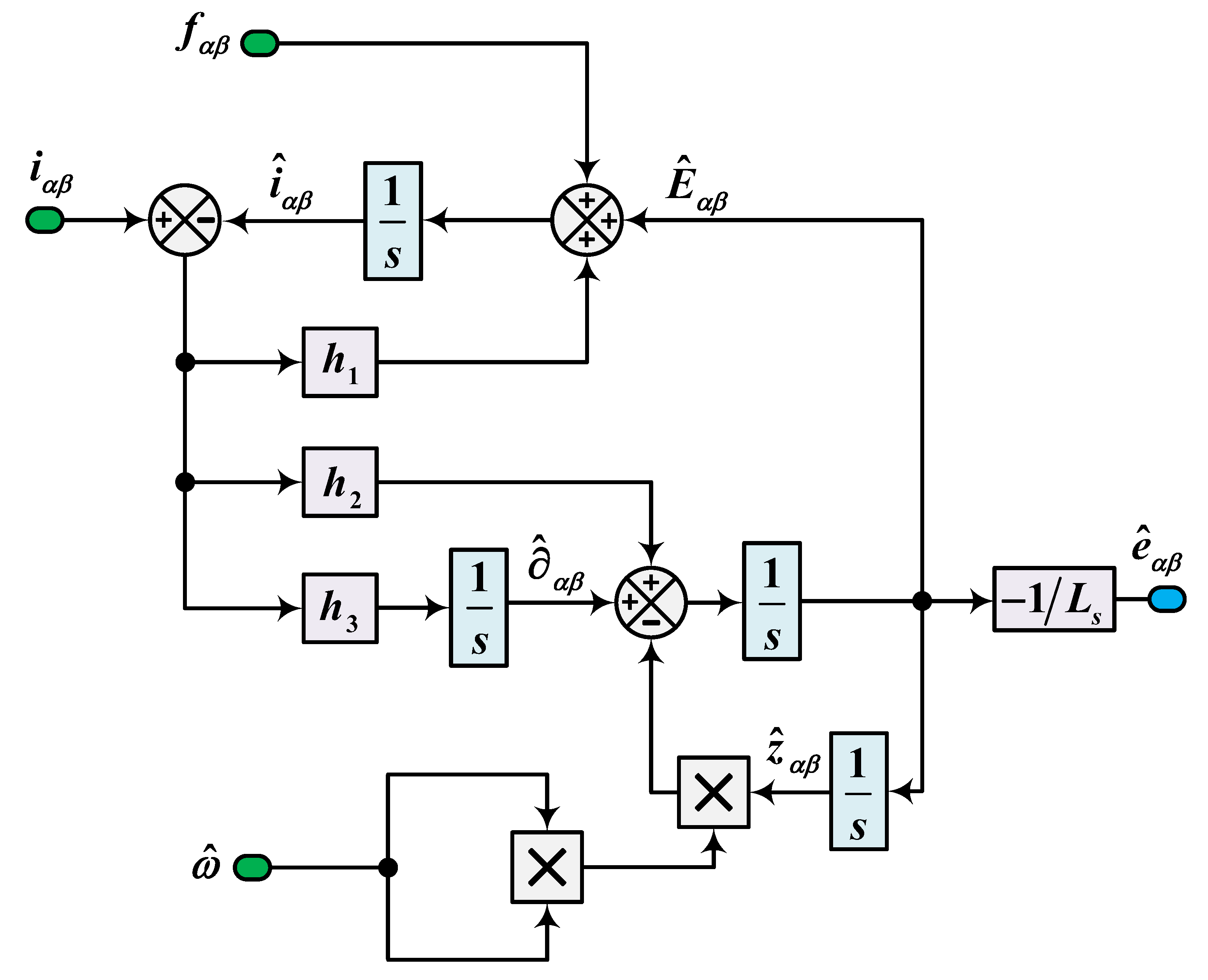
The proposed ESO operates by tracking the frequency of the back-EMF, which equals the estimated electrical speed. Its inputs are the estimated electrical speed , the current , and the known signal , as shown in Figure 3. This design is expanded by incorporating the differentiation of the back-EMF to compensate for the DC position error and phase lag. The design of the proposed ESO is detailed as follows:
where , , and represent constant observer gains.
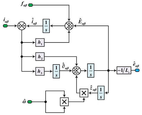
Figure 3.
Structural diagram of the proposed back-EMF ESO.
Similarly, applying the Laplace transform to (3) and (8) produces a transfer function that connects the estimated back-EMF to its actual value, as presented below.
To ensure the stability of the transfer function , the parameters must satisfy the following criterion derived from the Routh–Hurwitz stability analysis:
The observer gains , , and are tuned according to the selected ESO bandwidth and the estimated electrical rotor speed; their adjustments are implemented as follows:
where is the ESO bandwidth and must satisfy to ensure observer stability.
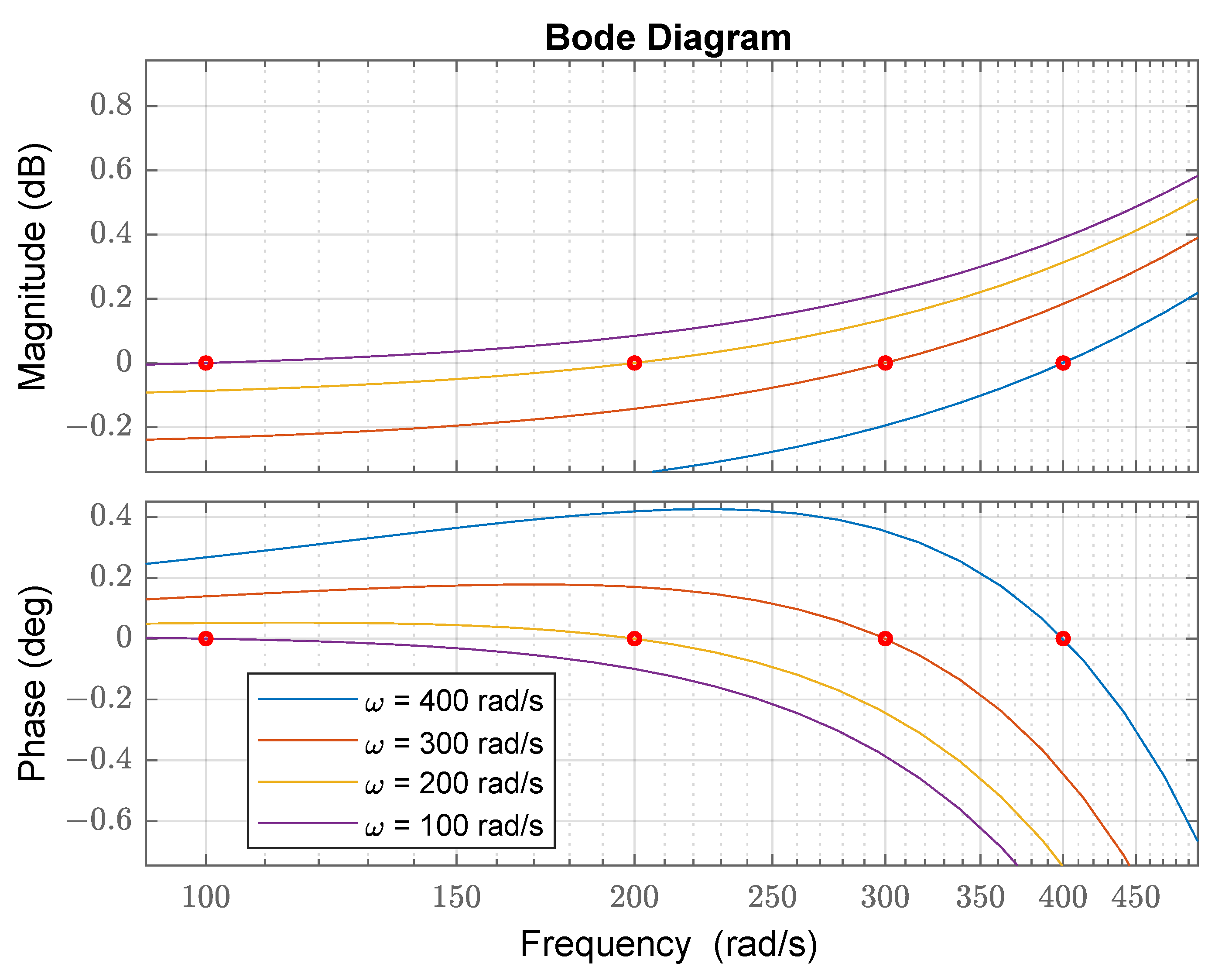
Figure 4 presents the Bode diagram of for back-EMF frequencies of 100, 200, 300, and 400 rad/s. The proposed ESO effectively minimizes DC error and phase lag across all tested frequencies with a fixed observer bandwidth of rad/s. This ensures accurate estimation without the need for higher bandwidth, improving robustness while maintaining performance.

Figure 4.
Bode diagram of the proposed back-EMF ESO.
4. QPLL Based on ESO
The direct method using the arc-tangent function introduces high-frequency noise in position estimation and may face computational challenges in extracting the estimated position and speed. To address these issues, the QPLL provides a robust and smooth approach for calculating the position estimation error from the estimated back-EMF, which can be formulated as follows:
where , and is the position estimation error.
Conventional phase-locked loop (PLL) methods, including QPLL based on a PI controller, are commonly used to extract estimated speed and position from the position estimation error. However, in PMSM control, uncertainties and disturbances affect the estimated back-EMF, making it difficult for the PI controller to provide accurate estimations. A more effective approach is to replace the PI controller with an extended state observer (ESO) to account for these uncertainties and disturbances.
Based on the equation of motion presented in (1), by clearly identifying the known and unknown disturbances, the dynamics can be reformulated as:
By treating the unknown disturbance as an extra state in the dynamics described by (13), we can derive the design of the third-order ESO as follows:
where , , and correspond to the observer gains. The gains are then adjusted based on the ESO bandwidth parameter , as indicated by the following expressions: , , and .
5. Design of Speed and Current Controllers
5.1. Speed Controller Design
The sliding surface is defined as:
The output speed control loop for generating the reference quadratic current can be designed as:
The unknown disturbance estimation error () and the time derivative of the speed estimation error () are treated as a perturbation term, which is assumed to be globally bounded according to the following condition:
where represents a positive bounding constant. As stated in [28], the system achieves strong global asymptotic stability if the gains fulfill the following conditions:
5.2. Current Controller Design
Predictive Current Control is chosen for the current controller design because it eliminates the need for parameter tuning, unlike conventional PI controllers, while ensuring optimal control performance.
To discretize the -frame current model of a PMSM, the current derivative is approximated using the forward Euler method with a sampling time of , as follows:
By applying (19) and (3), the predicted current model in the stationary frame is derived as follows:
The voltage components and are computed from the switching pulses applied to each up-leg of the inverter (, , ) in conjunction with the DC-link voltage (). Concurrently, the estimated back-EMF and are determined based on the estimated speed and position. The following equations detail how , , , and are calculated.
A three-phase inverter comprises eight switching states. However, (0,0,0) and (1,1,1) generate the same zero-voltage vector, yielding seven unique vectors (six active and one zero). At each sampling period, the voltage vector minimizing a cost function is selected. This cost function is designed to track the torque current reference, optimize torque per ampere, and enforce current magnitude limits, as defined below:
where and are the -frame current references, derived from the -frame current references via the inverse Park transformation. The quadrature-axis current reference () is generated by the speed controller, while the direct-axis current reference () is set to zero to achieve torque decoupling.
6. Recursive Least Squares
In the plane, the discrete model of the current equation for the PMSM can also be formulated as:
where y is the output vector, is the matrix of parameters to be estimated, and x is the input vector. Their definitions are as follows:
To estimate the parameter matrix in real time, a recursive least squares (RLSs) method is employed [29], which can be represented as:
where P denotes the covariance matrix, is the estimate of y computed using the estimated parameter matrix , and e represents the estimation error. The initial conditions are chosen to facilitate robust convergence: is typically initialized as a sufficiently large positive scalar multiplied by the identity matrix (i.e., with ), is set as a sufficiently small positive or zero vector, and the forgetting factor is commonly set to 1.
In sensorless PMSM control, accurate estimation of parameters such as inductance is particularly challenging due to their dependence solely on operating currents, similar to nonlinear inductors in power electronics applications [30]. Due to the complexity, nonlinearity, and strong coupling of PMSMs, using a fixed forgetting factor of 1 is ineffective. In recursive least squares, the forgetting factor () controls the weight of past data in the identification process. A lower prioritizes recent data, while a higher focuses more on older data. Therefore, selecting an optimal is crucial for balancing the rapid tracking of parameter variations with minimal excessive fluctuations.
To address these challenges, the conventional RLS algorithm was modified by incorporating an adaptive forgetting factor that adjusts dynamically based on the magnitude of the estimation error. In the modified algorithm, the forgetting factor is updated according to
where is the minimum allowable forgetting factor (facilitating rapid adaptation), is the maximum allowable forgetting factor (ensuring robust steady-state performance), and is a design parameter that sets the sensitivity of the update to the squared error magnitude. A large estimation error makes the exponential term very small, so moves closer to , allowing the algorithm to quickly forget old data and adapt to new changes. Conversely, when the error is small, the exponential term stays near 1, and remains close to , ensuring that more past data are used, which helps to reduce noise.
7. Results Analysis
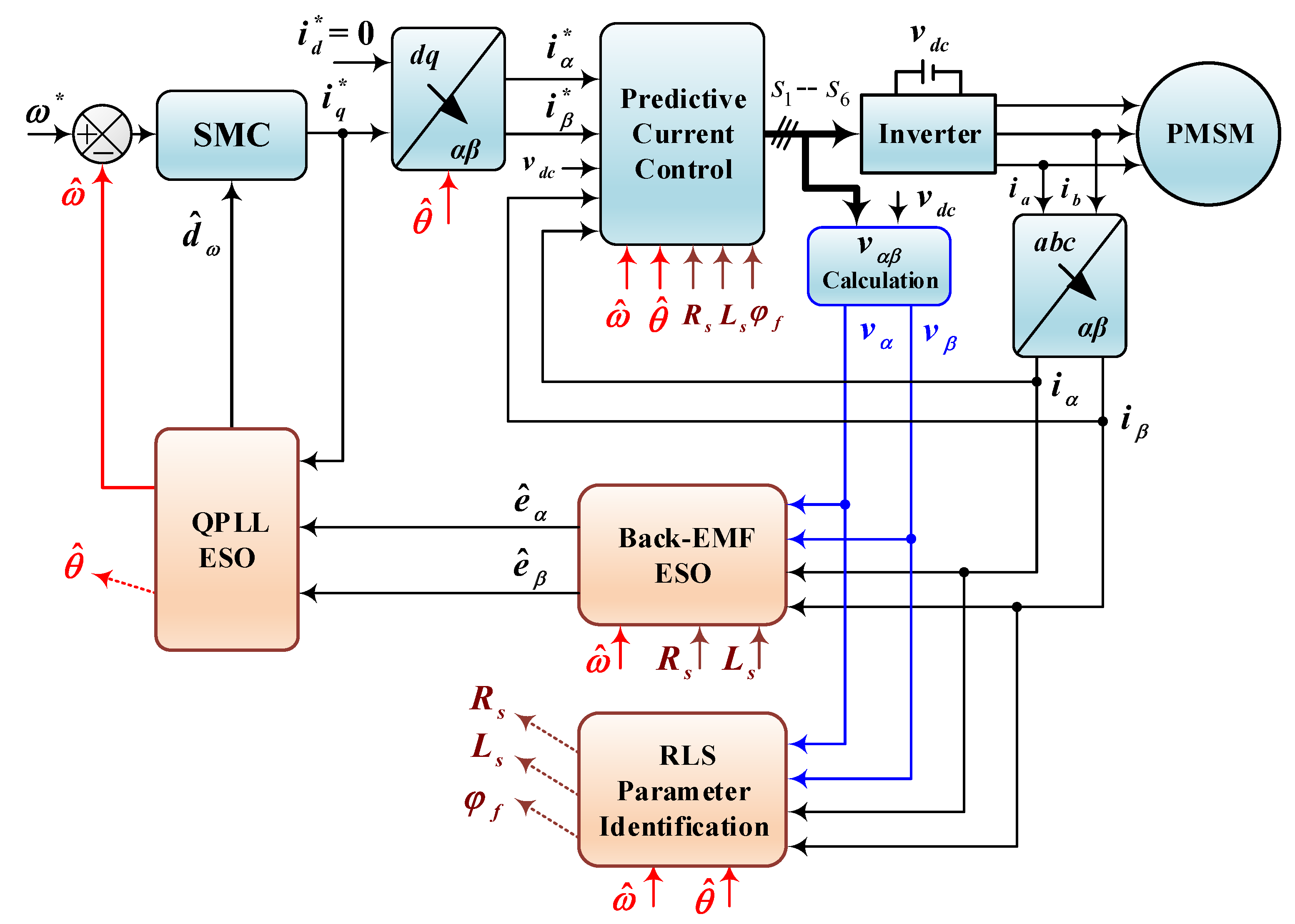
To evaluate the effectiveness of the proposed sensorless control strategy for PMSM, simulations were conducted in MATLAB (R2022b)/Simulink with a sampling time of , following the control structure shown in Figure 5, with motor parameters detailed in Table A1. Since back-EMF is absent at a standstill, the proposed method is not applicable at zero speed or during the brief startup phase. Sensorless control techniques relying on back-EMF estimation require the motor to be accelerated to a certain speed for accurate signal detection. In this study, the startup process followed the strategy outlined in [31], where a speed ramp-up frequency was applied while maintaining a q-axis current level dependent on load torque and regulating the d-axis current to zero. Once the motor reached the desired conditions, the proposed sensorless control was activated at 10 ms. To ensure a fair comparison, both the conventional and proposed back-EMF ESO bandwidths were set to = 50,000 rad/s, while the QPLL ESO bandwidth for speed and position estimation was configured to rad/s. To evaluate the robustness of the proposed sensorless control under parameter uncertainties, simulations were also performed with parameter deviations modeled as in (2), where the uncertainties were set to , , , and .
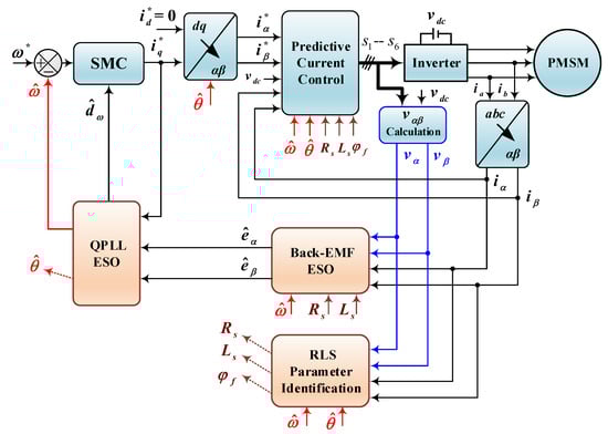
Figure 5.
Sensorless control structure diagram.
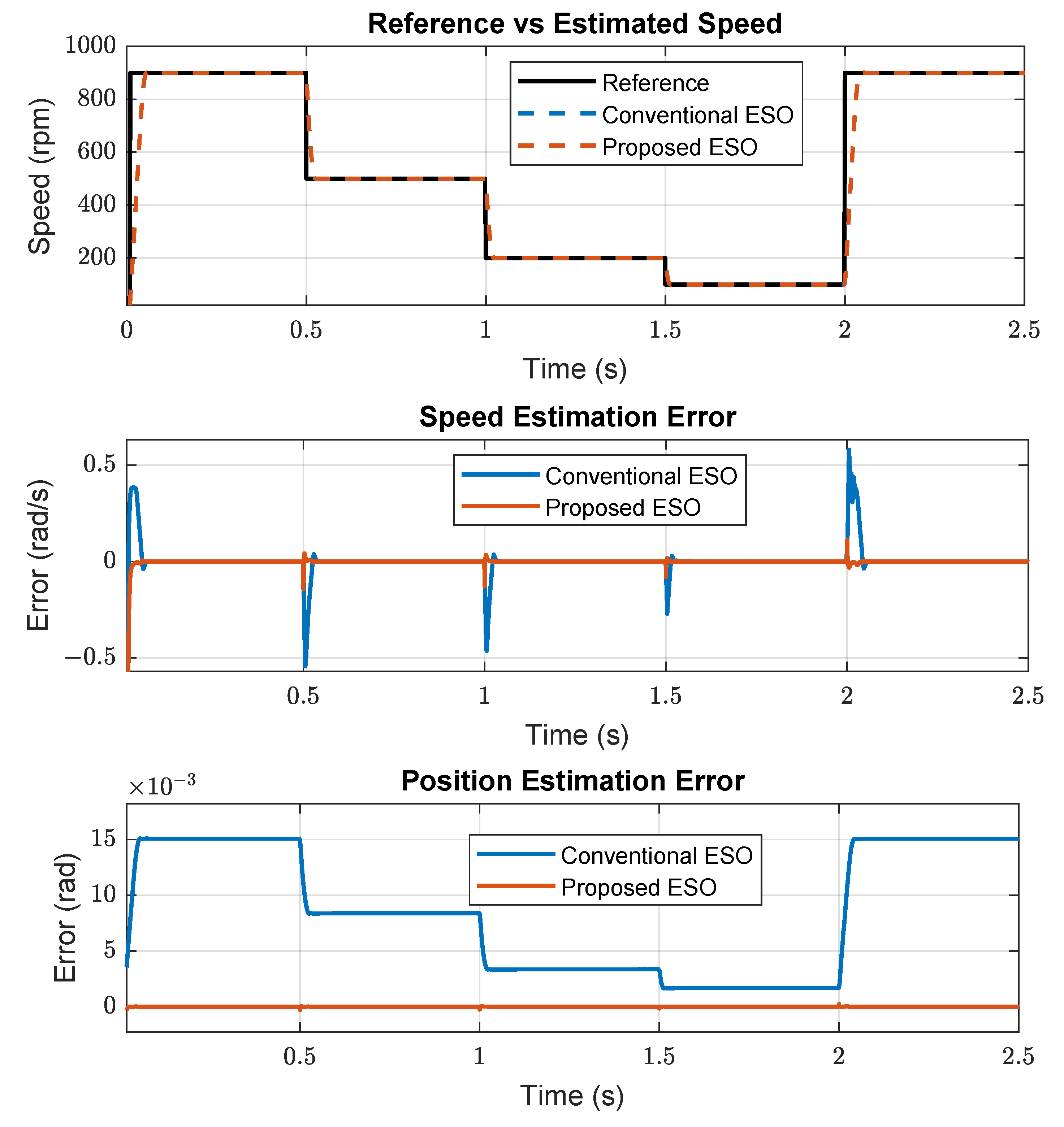
Figure 6 presents the performance comparison between the conventional and proposed back-EMF ESO under varying speed conditions with a rated load torque of 28.4 Nm. The top plot illustrates the actual and estimated speed trajectories, where both observers closely follow the reference speed. The reference speed starts at 900 rpm, then drops to 500 rpm at 0.5 s, followed by 200 rpm at 1 s and 100 rpm at 1.5 s, and then returns to 900 rpm at 2 s. The middle plot depicts the speed estimation error, showing that the conventional ESO experiences noticeable oscillations during speed transitions, whereas the proposed ESO maintains near-zero error. The bottom plot compares the position estimation error, demonstrating that the proposed ESO effectively eliminates DC position error and phase lag across different frequency operations, ensuring more accurate estimation than the conventional ESO.

Figure 6.
Comparison of back-EMF ESO performance.
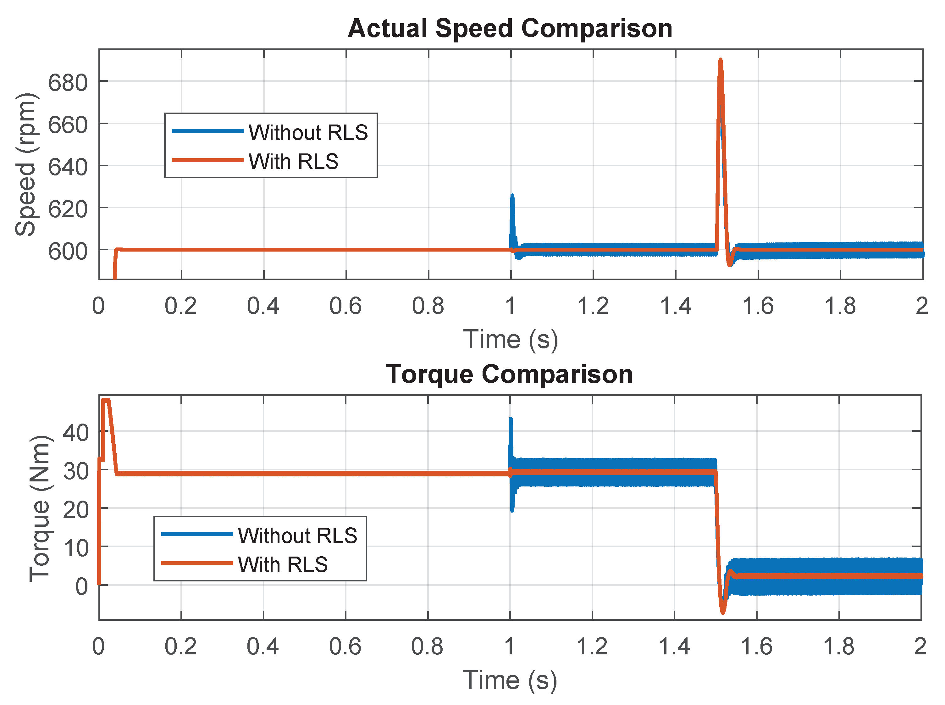
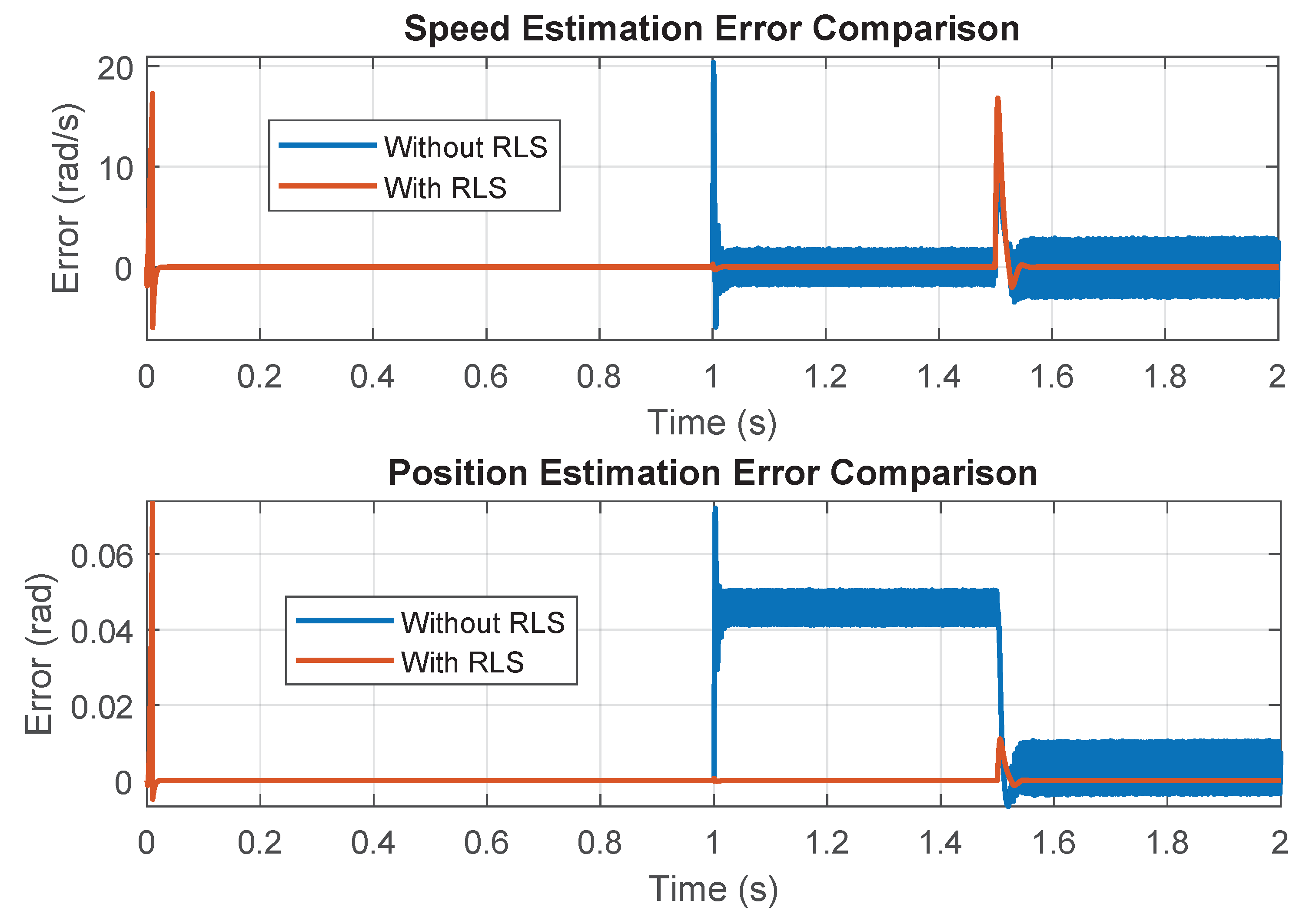
Figure 7 and Figure 8 present the performance comparison of the sensorless control of PMSM with and without the use of RLS parameter identification under parameter uncertainties. As previously described, parameter uncertainties (, , , and ) were applied at 1 s. The reference speed was set to 600 rpm, while the load torque was initially maintained at the rated value of 28.4 Nm and then reduced to 5% of the rated torque at 1.5 s. Figure 7 illustrates the actual speed and torque responses, where a noticeable deviation occurs after 1 s due to the applied uncertainties. The PMSM with RLS maintains a more stable speed and torque trajectory despite these variations, compared to the system without RLS. Figure 8 highlights the speed and position estimation errors, showing a significant increase in error after 1 s for the system without RLS, whereas the RLS-based approach effectively mitigates these errors, ensuring robustness and accuracy even in the presence of parameter uncertainties.

Figure 7.
Speed and torque with and without RLS.

Figure 8.
Speed and position errors with and without RLS.
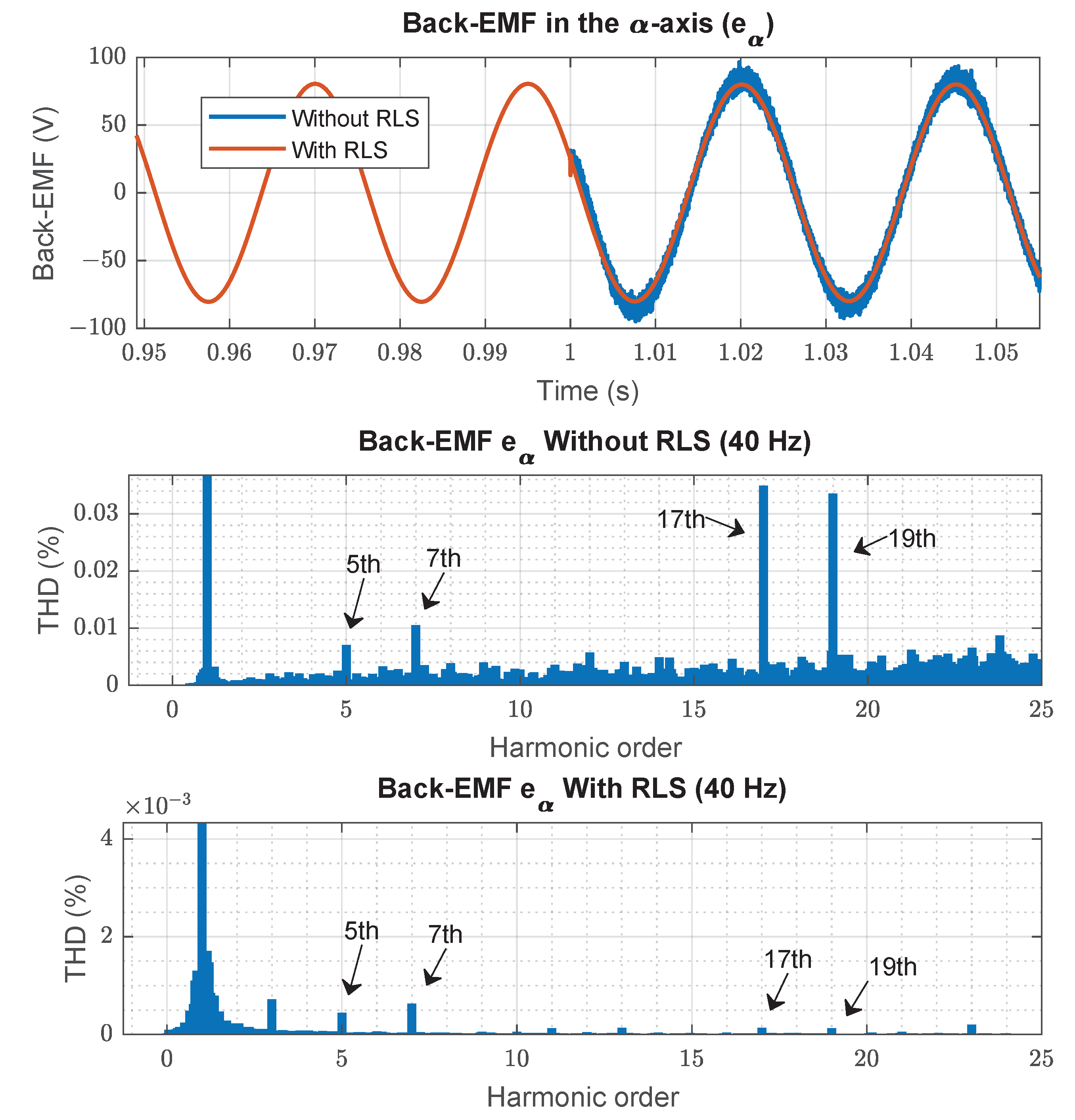
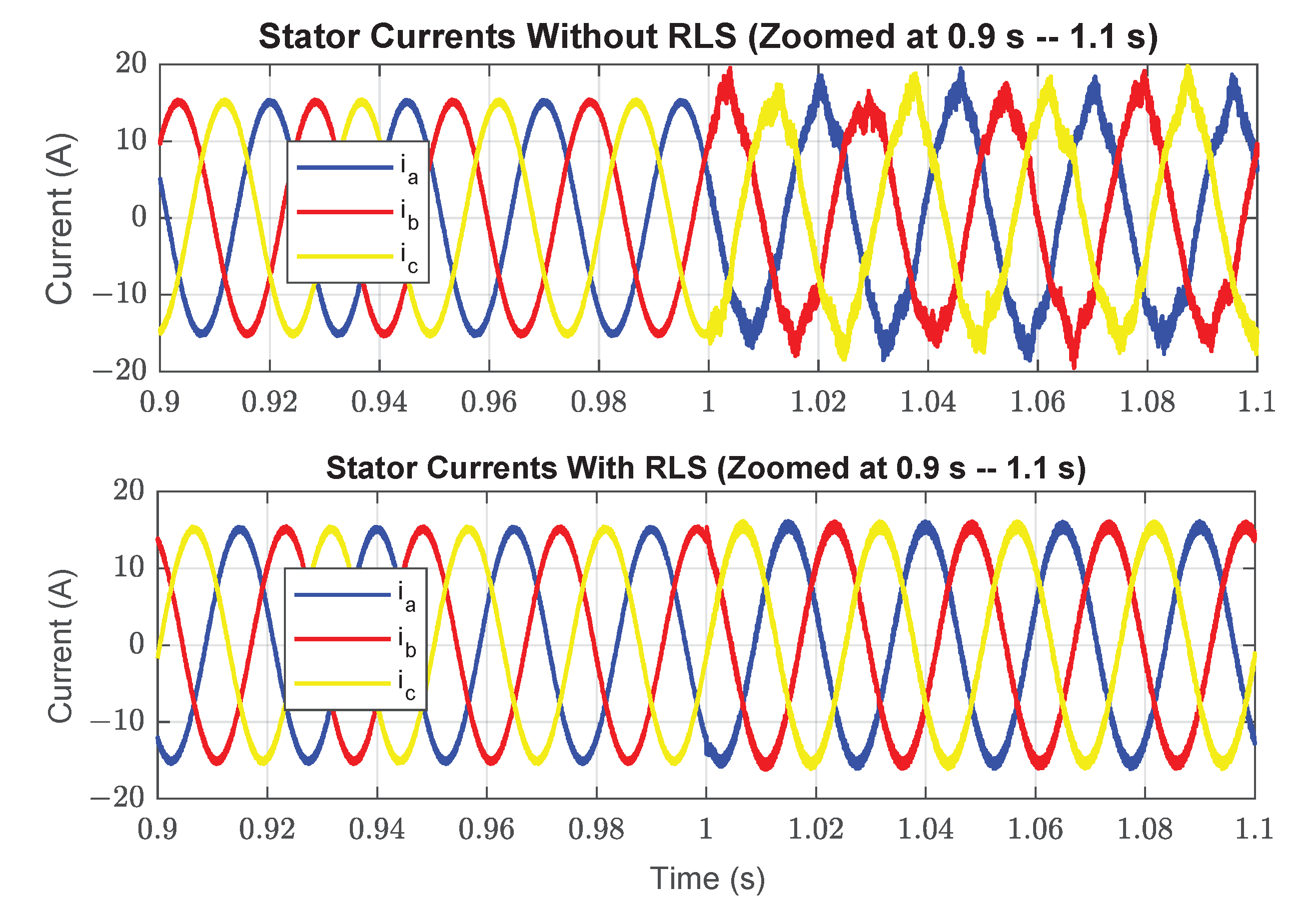
Figure 9 shows the performance of the back-EMF in the -axis for the PMSM under parameter uncertainties, comparing the cases without and with RLS parameter identification at the same speed reference of 600 rpm (40 Hz) with a rated load torque. In the top plot, parameter uncertainties were applied at 1 s, and the results show that the RLS-based approach achieves a smoother and more accurate back-EMF estimation despite these deviations. The middle plot presents the total harmonic distortion (THD) of the back-EMF without RLS, revealing a THD of 5.37% with prominent harmonic components at the 5th, 7th, 17th, and 19th orders. In contrast, the bottom plot demonstrates that the use of RLS significantly reduces the THD, effectively minimizing harmonic distortion and improving the overall quality of the back-EMF estimation under parameter uncertainty conditions. As shown in Table 1, this reduction in THD is not limited to the back-EMF but is also evident in the stator current, where the phase “a” current THD decreases from 8.36% to 2.77% with RLS. Additionally, Figure 10 further illustrates this effect by depicting the three-phase stator current waveforms for both cases, demonstrating that with RLS, the current waveforms remain smooth and unaffected by parameter uncertainties, closely resembling the ideal case without uncertainties.
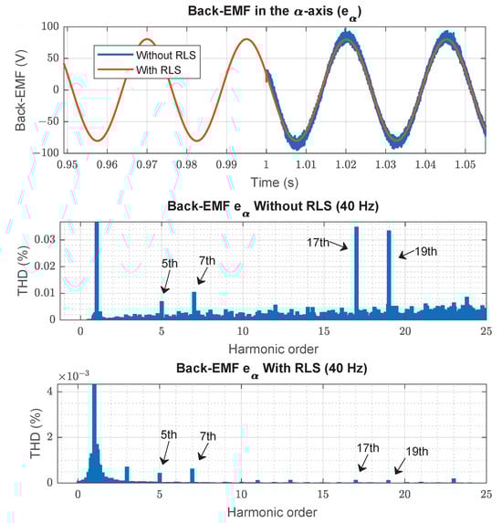
Figure 9.
Back-EMF and THD with and without RLS.

Table 1.
THD of back-EMF and stator current under parameter uncertainties.

Figure 10.
Stator current waveforms under parameter uncertainties with and without RLS.
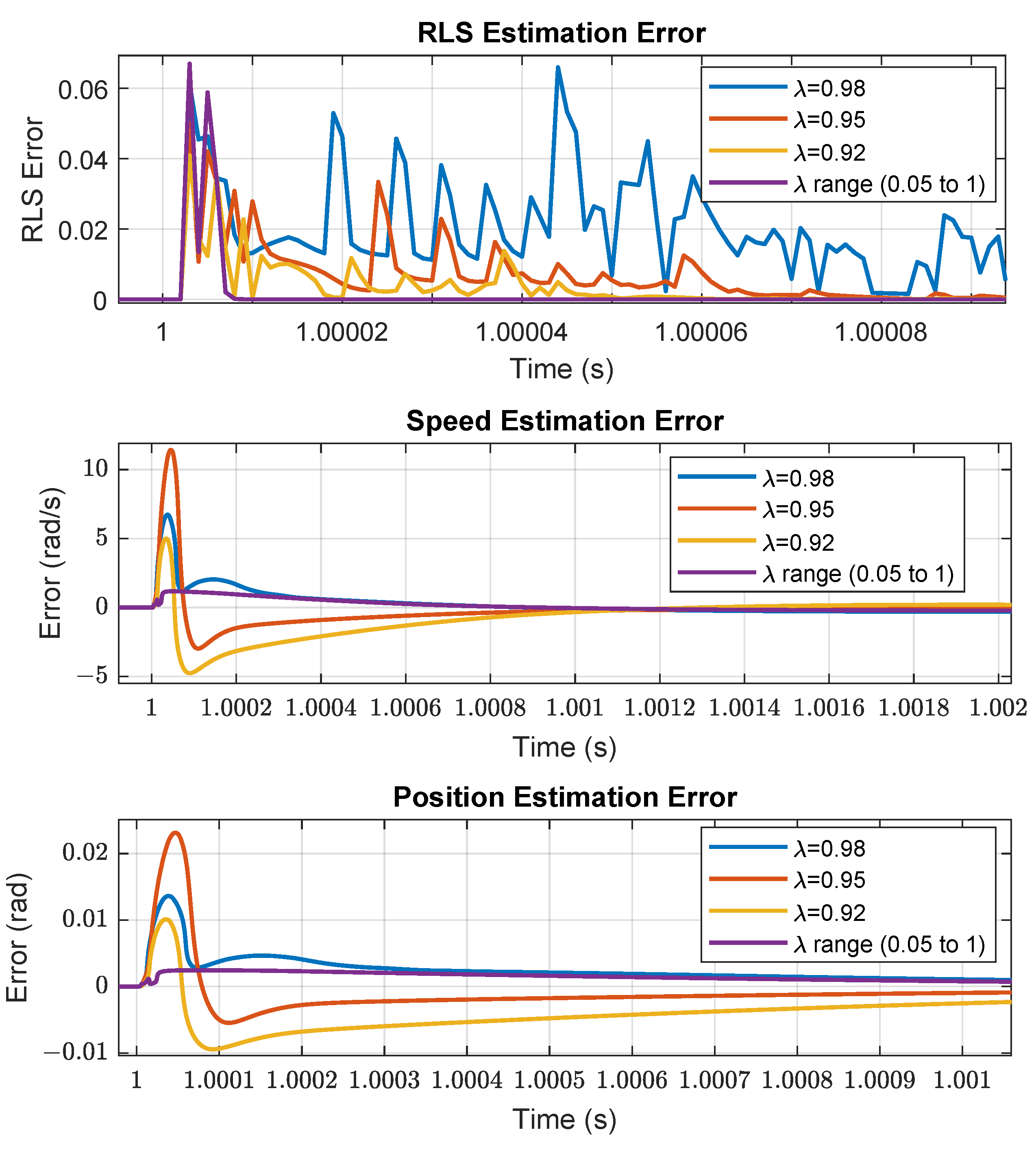
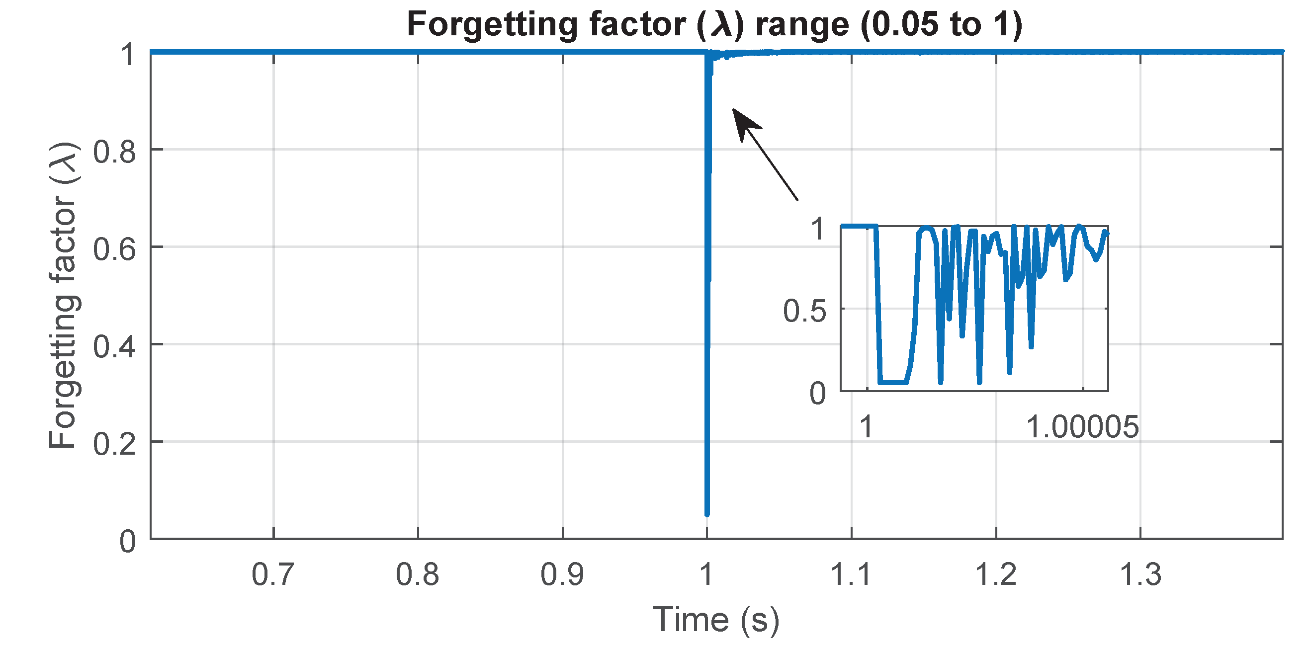
Figure 11 presents the estimation errors for RLS, speed, and position under both fixed and variable forgetting factor () values when parameter uncertainties occur at 1 s. The results demonstrate that a fixed struggles to balance adaptation speed and noise suppression, leading to increased fluctuations in estimation errors. In contrast, the adaptive effectively reduces estimation errors, ensuring better tracking performance. Figure 12 illustrates the dynamic behavior of the adaptive , which varies between 0.05 and 1, allowing the algorithm to adjust in real time. This flexibility enhances the robustness of the estimation process by providing fast adaptation during transients while maintaining stability in steady state.

Figure 11.
Different forgetting factor () values.

Figure 12.
Forgetting factor () range (0.05 to 1).
8. Conclusions
This paper presents a robust sensorless control strategy for PMSM based on a back-EMF extended state observer (ESO), which effectively eliminates DC position error compared to conventional ESO. With the addition of another ESO in the quadrature phase-locked loop (QPLL), not only can speed and position be accurately estimated, but it also enables the identification of unknown disturbances in the speed loop, allowing the sliding mode controller (SMC) to achieve faster convergence and improved disturbance rejection. Additionally, the proposed approach integrates a recursive least squares (RLSs) algorithm to enhance robustness against parameter uncertainties. A key improvement is the use of a variable forgetting factor instead of a fixed value, addressing the trade-off between adaptation speed and noise suppression. The results demonstrate that a fixed struggles to maintain this balance, leading to increased fluctuations in estimation errors, whereas the adaptive effectively reduces estimation errors, ensuring better tracking performance by enabling fast adaptation during transients while maintaining stability in the steady state. This flexibility significantly enhances the robustness of the estimation process.
Author Contributions
Methodology, A.D., H.M., M.F.B. and S.Z.; writing—original draft, A.Z., A.D. and H.M. All authors have read and agreed to the published version of the manuscript.
Funding
This research received no external funding.
Institutional Review Board Statement
Not applicable.
Informed Consent Statement
Not applicable.
Data Availability Statement
Data are contained within the article.
Conflicts of Interest
The authors declare no conflicts of interest.
Appendix A
Table A1.
Motor parameters.
Table A1.
Motor parameters.
| Parameter | Value |
|---|---|
| Rated Power | 4400 W |
| Rated Current | A |
| Rated Torque | N·m |
| Number of Pole Pairs () | 4 |
| Stator Resistance () | |
| Stator Inductance ( | mH |
| Rotor Flux Linkage () | Wb |
| Moment of Inertia (J) | Kg·m2 |
| Friction Coefficient (f) | Nms |
References
- Tu, C.C.; Hung, C.L.; Hong, K.B.; Elangovan, S.; Yu, W.C.; Hsiao, Y.S.; Lin, W.C.; Kumar, R.; Huang, Z.H.; Hong, Y.H.; et al. Industry perspective on power electronics for electric vehicles. Nat. Rev. Electr. Eng. 2024, 1, 435–452. [Google Scholar] [CrossRef]
- Chen, H.; Tang, J.; Liu, Y.; Jiang, B.; Boscaglia, L. Electromagnetic Performance Investigation of a Brushless Electrically Excited Synchronous Machine for Long-Distance Heavy-Duty Electric Vehicles. IEEE Trans. Transp. Electrif. 2025, 11, 225–235. [Google Scholar] [CrossRef]
- Guo, Y.; Liu, L.; Ba, X.; Lu, H.; Lei, G.; Yin, W.; Zhu, J. Designing High-Power-Density Electric Motors for Electric Vehicles with Advanced Magnetic Materials. World Electr. Veh. J. 2023, 14, 114. [Google Scholar] [CrossRef]
- Liu, T.; Zhao, Q.; Zhao, K.; Li, L.; Zhu, G. Sensorless model predictive control of permanent magnet synchronous motor based on hybrid parallel observer under parameter uncertainty. IET Power Electron. 2024, 17, 438–449. [Google Scholar] [CrossRef]
- Akrami, M.; Jamshidpour, E.; Baghli, L.; Frick, V. Application of Low-Resolution Hall Position Sensor in Control and Position Estimation of PMSM—A Review. Energies 2024, 17, 4216. [Google Scholar] [CrossRef]
- Huang, Y.; Zhao, M.; Zhang, J.; Lu, M. The Hall Sensors Fault-Tolerant for PMSM Based on Switching Sensorless Control with PI Parameters Optimization. IEEE Access 2022, 10, 114048–114059. [Google Scholar] [CrossRef]
- Chi, W.C.; Cheng, M.Y. Implementation of a sliding-mode-based position sensorless drive for high-speed micro permanent-magnet synchronous motors. ISA Trans. 2014, 53, 444–453. [Google Scholar] [CrossRef]
- Sahebjam, M.; Sharifian, M.B.; Feyzi, M.R.; Sabahi, M. Novel methodology for direct speed control of a permanent magnet synchronous motor with sensorless operation. IET Electr. Power Appl. 2021, 15, 728–741. [Google Scholar] [CrossRef]
- Dong, S.; Zhou, M.; Wang, C.; Gou, L.; You, X. Improved Hybrid Sensorless Control for IPMSM in Full Speed Range at Low Switching Frequency. IEEE Trans. Energy Convers. 2024, 40, 123–135. [Google Scholar] [CrossRef]
- Shi, L.; Lv, M.; Li, P. Sensorless Position Control in High-Speed Domain of PMSM Based on Improved Adaptive Sliding Mode Observer. Processes 2024, 12, 2581. [Google Scholar] [CrossRef]
- R, S.; Singh, B. Sensorless Predictive Control of SPMSM-Driven Light EV Drive Using Modified Speed Adaptive Super Twisting Sliding Mode Observer with MAF-PLL. IEEE J. Emerg. Sel. Top. Ind. Electron. 2021, 2, 42–52. [Google Scholar] [CrossRef]
- Zhou, Q.; Wang, Y.; Zhang, Y.; Zhang, L.; Shi, K. Sensorless control of permanent magnet synchronous motor based on improved sliding mode observer. Trans. Inst. Meas. Control 2025, 47, 194–205. [Google Scholar] [CrossRef]
- Zeghlache, A.; Mekki, H.; Djerioui, A.; Benkhoris, M.F. Sensorless Control of BLDC Motor Based on ESO with an Active Harmonic Compensator. J. Control Autom. Electr. Syst. 2024, 35, 960–969. [Google Scholar] [CrossRef]
- Wang, H.; Zhang, G.; Liu, X. Sensorless Control of Surface-Mount Permanent-Magnet Synchronous Motors Based on an Adaptive Super-Twisting Sliding Mode Observer. Mathematics 2024, 12, 2029. [Google Scholar] [CrossRef]
- Tian, B.; Li, Y.; Hu, J.; Wang, G.; Molinas, M.; Zhang, G.; Wang, K.; Zhang, Z. A Wide Speed Range Sensorless Control for Three-Phase PMSMs Based on a High-Dynamic Back EMF Observer. IEEE Trans. Transp. Electrif. 2025, 11, 4336–4349. [Google Scholar] [CrossRef]
- Harshit Mohan, M.K.P.; Dwivedi, S.K. Sensorless Control of Electric Drives—A Technological Review. IETE Tech. Rev. 2020, 37, 504–528. [Google Scholar] [CrossRef]
- Jiang, N.; Cao, R.; Sun, W.; Chen, D.; Wang, K. MRAS-based Sensorless Control of PMSM Drives Using Extended State Observer in Shaftless Rim-driven Thruster System. IEEE Trans. Transp. Electrif. 2024, 1. [Google Scholar] [CrossRef]
- Zuo, Y.; Lai, C.; Iyer, K.L.V. A Review of Sliding Mode Observer Based Sensorless Control Methods for PMSM Drive. IEEE Trans. Power Electron. 2023, 38, 11352–11367. [Google Scholar] [CrossRef]
- Jiang, F.; Sun, S.; Liu, A.; Xu, Y.; Li, Z.; Liu, X.; Yang, K. Robustness Improvement of Model-Based Sensorless SPMSM Drivers Based on an Adaptive Extended State Observer and an Enhanced Quadrature PLL. IEEE Trans. Power Electron. 2021, 36, 4802–4814. [Google Scholar] [CrossRef]
- Chen, S.; Ding, W.; Hu, R.; Wu, X.; Shi, S. Sensorless Control of PMSM Drives Using Reduced Order Quasi Resonant-Based ESO and Newton–Raphson Method-Based PLL. IEEE Trans. Power Electron. 2023, 38, 229–244. [Google Scholar] [CrossRef]
- Jiang, F.; Yang, F.; Sun, S.; Yang, K. Static-Errorless Rotor Position Estimation Method Based on Linear Extended State Observer for IPMSM Sensorless Drives. Energies 2022, 15, 1943. [Google Scholar] [CrossRef]
- Sun, H.; Zhang, X.; Liu, X.; Su, H. Adaptive Robust Sensorless Control for PMSM Based on Improved Back EMF Observer and Extended State Observer. IEEE Trans. Ind. Electron. 2024, 71, 16635–16643. [Google Scholar] [CrossRef]
- Sreejith, R.; Singh, B. Sensorless Predictive Current Control of PMSM EV Drive Using DSOGI-FLL Based Sliding Mode Observer. IEEE Trans. Ind. Electron. 2021, 68, 5537–5547. [Google Scholar] [CrossRef]
- Li, X.; Cui, Y.; Wu, X. Sensorless Control of Surfaced-Mounted Permanent Magnet Synchronous Motor in a Wide-Speed Range. Electronics 2024, 13, 1131. [Google Scholar] [CrossRef]
- Chen, S.; Ding, W.; Wu, X.; Hu, R.; Shi, S. Finite Position Set-Phase-Locked Loop with Low Computational Burden for Sensorless Control of PMSM Drives. IEEE Trans. Ind. Electron. 2023, 70, 9672–9676. [Google Scholar] [CrossRef]
- Yu, Y.; Shao, Y.; Chai, F.; Cui, M. Static-Errorless Position Estimation for Sensorless PMSM Drives with Enhanced Robustness Against the Full-Frequency Domain Disturbance. IEEE Trans. Power Electron. 2022, 37, 5884–5897. [Google Scholar] [CrossRef]
- Yu, K.; Li, S.; Zhu, W.; Wang, Z. Sensorless Control Scheme for PMSM Drive via Generalized Proportional Integral Observers and Kalman Filter. IEEE Trans. Power Electron. 2025, 40, 4020–4033. [Google Scholar] [CrossRef]
- Moreno, J.A.; Osorio, M. A Lyapunov approach to second-order sliding mode controllers and observers. In Proceedings of the 2008 47th IEEE Conference on Decision and Control, Cancun, Mexico, 9–11 December 2008; pp. 2856–2861. [Google Scholar] [CrossRef]
- Ichikawa, S.; Tomita, M.; Doki, S.; Okuma, S. Sensorless control of permanent-magnet synchronous motors using online parameter identification based on system identification theory. IEEE Trans. Ind. Electron. 2006, 53, 363–372. [Google Scholar] [CrossRef]
- Yao, Z.; Lan, H.; He, X.; Deng, F.; Wang, C.; Lu, S.; Tang, Y. Nonlinear Inductor-Based Single Sensor Current Balancing Method for Interleaved DC–DC Converters. IEEE Trans. Power Electron. 2024, 39, 3996–4000. [Google Scholar] [CrossRef]
- Wang, Z.; Lu, K.; Blaabjerg, F. A Simple Startup Strategy Based on Current Regulation for Back-EMF-Based Sensorless Control of PMSM. IEEE Trans. Power Electron. 2012, 27, 3817–3825. [Google Scholar] [CrossRef]
Disclaimer/Publisher’s Note: The statements, opinions and data contained in all publications are solely those of the individual author(s) and contributor(s) and not of MDPI and/or the editor(s). MDPI and/or the editor(s) disclaim responsibility for any injury to people or property resulting from any ideas, methods, instructions or products referred to in the content. |
© 2025 by the authors. Licensee MDPI, Basel, Switzerland. This article is an open access article distributed under the terms and conditions of the Creative Commons Attribution (CC BY) license (https://creativecommons.org/licenses/by/4.0/).