Article

An Integrated RF Sensor Design for Anchor-Free Collaborative Localization in GNSS-Denied Environments

1
College of Electronics and Information Engineering, South-Central Minzu University, Wuhan 430074, China
2
Wuhan Shipboard Communication Institute, Wuhan 430079, China
3
Yunnan Key Laboratory of Unmanned Autonomous Systems, Kunming 650500, China
4
School of Electrical and Information Engineering, Yunnan Minzu University, Kunming 650500, China
*
Author to whom correspondence should be addressed.
Electronics 2025, 14(8), 1667; https://doi.org/10.3390/electronics14081667
Submission received: 10 March 2025 / Revised: 15 April 2025 / Accepted: 17 April 2025 / Published: 20 April 2025

Abstract

:
To address the challenge of collaborative nodes being unable to accurately perceive each other’s positions in global navigation satellite system (GNSS)-denied environments (such as after hostile interference or in urban canyons), we propose a GNSS-independent collaborative positioning radio frequency (RF) sensor. This sensor estimates inter-node distances and orientations using wireless measurements between nodes, without requiring pre-deployed anchor points. First, we designed a low-nanosecond latency ranging logic circuit on field-programmable gate array (FPGA) hardware, enabling relative distance estimation between nodes via a low-latency collaborative ranging (LLCR) algorithm without synchronization. Additionally, a synthetic aperture rotating antenna system was built to construct an echo space energy distribution matrix, based on dynamic–static dual-channel phase differences for high-precision, unambiguous azimuth measurement, followed by angle and distance data integration for localization. Then, a novel RF sensor hardware system was designed that was lightweight, low in cost, and high in performance. Finally, two generations of prototype models were developed and tested in both an anechoic chamber and mounted on unmanned vehicles outdoors in fields. The results demonstrate that the proposed sensor can achieve high-precision relative position estimation between collaborative nodes in the absence of GNSS, with a positioning error of within 0.4 m, indicating that it is suitable for mounting on unmanned vehicles and other autonomous systems for collaborative positioning.

1. Introduction

As unmanned systems continue to proliferate, their coordination across the multidimensional domains of air, space, and the ground is poised to become the primary mode of operation and combat in the future. This will unfold within the context of complex information setups formed through the integration of these domains. Due to considerations of cost, size, weight, and power consumption, with the aid of system-on-chip (SoC) and software radio technologies, unmanned systems have evolved into sensors with multiple RF functions, including radar, communication, navigation, and electronic warfare. Their real-time, high-precision position data play a crucial role across various fields [1,2,3,4,5,6]. GNSS can provide meter-level positioning information in open outdoor environments. However, its signals are weak and prone to interference, making it difficult to achieve reliable positioning in obstructed or interference-prone environments. As a result, GNSS-based positioning technologies struggle to deliver high-quality navigation signals in GNSS-denied environments, such as urban canyons, forests, and indoors. With the advancement of collaborative positioning technologies, relative position estimation between unmanned systems through communication and detection via RF sensor nodes, without relying on GNSS satellites, has become a promising alternative [7,8,9,10].
Recently, cooperative positioning has attracted widespread attention and investigation, with notable advancements in key positioning techniques, including the angle of arrival (AOA), received signal strength (RSS), time of arrival (TOA), time difference of arrival (TDOA), and round-trip time (RTT) [11,12,13,14,15]. Based on the above measurement methods, collaborative localization in RF sensor setups primarily relies on the assistance of multiple anchor points with known positions and synchronized clocks to achieve high-precision node location estimation. In contrast, an anchor-free positioning strategy achieves collaborative positioning of neighboring nodes through communication and detection between distributed sensor nodes, without the need for predefined reference nodes. This approach provides greater flexibility and scalability while reducing operational costs, providing distinct advantages in terms of dynamic and large-scale unmanned applications [16,17,18].

1.1. Related Work

Extensive research efforts have been devoted to achieving anchor-free cooperative localization for unmanned systems, aiming to improve positioning accuracy while effectively reducing energy consumption. Specifically, in [19], a mapping-based three-dimensional (3D) positioning scheme has been proposed, which utilizes the connectivity graph of the sensor setup and its deployed digital terrain model (DTM) to extract triangular meshes and identify feature points with inherent surface distance geometric properties, enabling the construction of well-aligned mapping for node localization without anchor-based location information. Leveraging this mapping construct, each sensor node can reference the grid points in the DTM to accurately determine its own geographic position. To overcome the challenge of degraded localization accuracy due to anisotropy in wireless sensor networks (WSNs), the authors of [20] proposed an advanced Sun Flower optimization algorithm (SFO), which employs distance vector-hop (DV-Hop) techniques in range-free and anchor-free scenarios to accurately localize unknown nodes, with data analysis demonstrating a substantial improvement in localization precision compared to existing models. Expanding on these advancements to meet energy efficiency demands, the authors of [21] implemented anchor-free positioning for effective work deployment in harsh environments, which leverages RSSI, along with the Kleincroch model and Al-Kashi theorem, to achieve effective deployment without considering the topology of each cluster, allowing all wireless sensors to perform positioning at extremely low positioning error rates while greatly reducing energy consumption. In addition, the authors of [22] introduced an anchor-free positioning algorithm for single-hop nodes, based on RSS and centroid technology, estimating node positions using the average distance between neighboring nodes. The simulation results show that, with the same node density and work scale, this algorithm significantly outperforms conventional localization techniques. Furthermore, the authors of [23] achieved precise localization by exchanging beacon data between the base station’s rotating antenna and ordinary nodes, enhancing localization accuracy while optimizing both localization time and energy efficiency, without relying on anchor nodes.

1.2. Motivation and Contributions

While prior works have put forward effective strategies to enhance relative positioning estimation capabilities between unmanned systems, several key technical aspects have yet to be fully investigated in the existing literature. First, due to the need for concealment and energy constraints, unmanned systems generally limit inter-node communication frequency. Achieving this goal requires the development of an efficient sensor that facilitates nodes to obtain critical information and complete the localization process rapidly within a limited number of communication exchanges. Second, acquiring sufficient positioning information typically requires sophisticated antenna array configurations and advanced spatial matrix processing. However, deploying multiple antennas at each sensor node is costly; meanwhile, inter-antenna coupling, hardware constraints, and the computational burden of complex matrix decomposition make it challenging for nodes to efficiently achieve high-precision positioning. Therefore, designing a positioning algorithm with fewer antennas and lower computational complexity is essential for optimizing sensing performance and ensuring the timely execution of tasks. Third, in unmanned application scenarios, each sensor node generally operates independently for signal transmission and reception, necessitating clock synchronization for high-precision positioning results. Moreover, the dynamic nature of real-world environments necessitates that synchronization algorithms exhibit greater robustness and adaptability to address the challenges posed by such variations.
Motivated by these issues with existing systems, we aimed to develop a novel method for the collaborative positioning of anchor-free RF sensor setups, tailored to GNSS-denied scenarios, while also engineering the requisite sensor hardware to support this approach. Specifically, on the one hand, this study presents a low-frequency, low-energy LLCR algorithm for rapid real-time distance estimation in asynchronous nodes. On the other hand, we introduce an advanced unambiguous direction-finding method that accurately determines the target’s spatial angle using only two antennas. By further combining the angle and distance information, the target’s relative position can be precisely obtained. Additionally, we have refined the design and optimized the sensor hardware system in detail. Numerical experiments clearly verify the superior positioning performance of this proposed algorithm, as well as confirming the practical applicability of this designed sensor.
The main contributions of this study are summarized as follows:
  • In contrast to existing studies, we consider a more challenging but realistic unmanned vehicle system collaborative localization scenario in a GNSS-denied environment, where each unmanned vehicle is equipped with a multifunctional integrated RF sensor to achieve target position awareness through a hybrid AOA/TOA measurement approach.
  • To achieve high-precision real-time positioning, we present a novel anchor-free positioning scheme that fully utilizes dual-channel sensor communication and detection capabilities. First, based on inter-node communication, the LLCR algorithm, implemented using an FPGA logic array, is proposed to facilitate the position estimation of neighboring asynchronous nodes within nanosecond-level latency. Then, this paper introduces a dual-channel unambiguous analogous synthetic aperture radar (ASAR) azimuth measurement method. Finally, we realize the relative position estimation of neighboring nodes by organically fusing and aligning the azimuth data with the distance data.
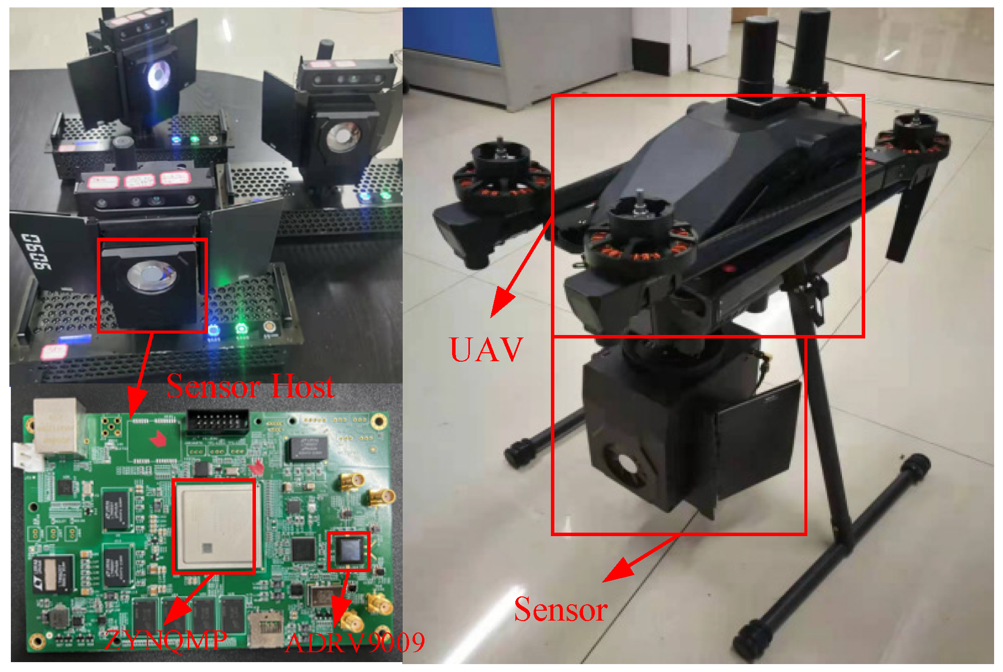
  • To better validate the performance of the proposed positioning algorithm in real-world scenarios, we selected a highly integrated, low-power dual-channel RF transceiver and designed the sensor based on the principles of hardware reuse and software-based sensing, maximizing hardware resource utilization while integrating the positioning algorithm, achieving the unification of communication and sensing functions. Through an efficient exchange of information with neighboring nodes, the sensor enables precise positional awareness of asynchronous collaborative nodes in GNSS-denied environments. Subsequently, we complete the development of two generations of prototypes.
  • Both anechoic chamber tests and outdoor field experiments with unmanned vehicles demonstrate that our sensors can achieve high-precision relative position estimation between collaborative nodes, maintaining a positioning error within 0.4 m in GNSS-denied environments, strengthening the robustness of the unmanned vehicle collaborative positioning system while reducing infrastructure costs and system complexity for sensor localization.
The rest of this paper is structured as follows. Section 2 develops a mathematical model for wireless signal multipath transmission and reception, providing a detailed overview of the proposed LLCR algorithm, which is implemented using FPGA hardware logic, as well as the high-precision azimuth measurement algorithm based on ASAR. Section 3 introduces the design of the sensor hardware system, encompassing the overall system architecture, core chipset, antenna structure, and other key components. Section 4 verifies the functionality and performance of the first-generation and second-generation sensors in anechoic chamber environments and in field scenarios with unmanned vehicles. Finally, our conclusions are presented in Section 5.

2. Design of the Collaborative Relative Positioning Algorithm

2.1. FPGA-Based LLCR Algorithm

2.1.1. System Model

For a clearer illustration of the LLCR algorithm, this subsection formulates a mathematical model for wireless signal multipath propagation. Assuming that N collaborative positioning sensor nodes, operating independently within a shared two-dimensional (2D) space, are mounted on unmanned test vehicles in a GNSS-denied environment where satellite navigation signals are unavailable, the nodes can only perceive the positions of neighboring nodes through their onboard RF sensors. User nodes are identified as N = { 1,2 , , N a } , and, within a single communication frame, the baseband signal received by node i from others can be expressed as:
c i t = j N , j i m = 1 L i j α i j m z j t τ i j m + w i t ,
where z j ( t ) represents the baseband signal transmitted by node j , L i j indicates the number of multipath components from node j to node i , α i j m and τ i j m correspond to the amplitude and the phase delay of the m-th multipath echo, respectively, and w i t denotes Gaussian white noise. The arrival time of the signal transmitted from node j to node i via the m-th path can be described as:
τ i j m = d i j m c + ς j ς i   ,
where c is the speed of light, and d i j m represents the straight-line distance that the signal travels from node j to node i through the m-th path, while ς j and ς i denote the clock biases of nodes j and i , respectively.
d i j 1 = | | p i p j | | 2 ,
here, p i and p j represent the 2D coordinates of node i and node j , respectively.
Notably, this paper considers a wireless detection setup in a quasi-static scenario, which means that all nodes are stationary during the short-term wireless detection signal transmission period, and the channels between them are equal.

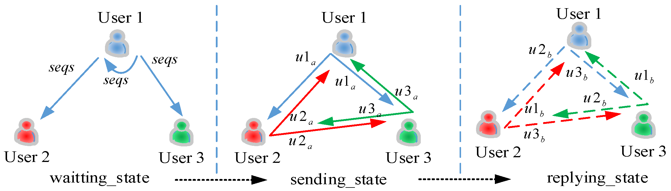
2.1.2. Measuring Demo with Three Nodes

This subsection describes the LLCR algorithm principle through the example of collaborative detection among three nodes. Figure 1 presents a schematic of relative distance measurement between three nodes through wireless detection. In order to distinguish the node identifications (IDs) and improve the signal-to-noise ratio (SNR) of the transmitted signal, each node is assigned a set of pseudo-random pairs, denoted as u x a and u x b , prior to the measurement, which are used for the second-stage transmission and third-stage reply, respectively. The pseudo-random sequences u x a assigned to each node exhibit strong autocorrelation and cross-correlation properties, ensuring the reliable detection of each node’s ID information within the superimposed waveform signals. The entire detection process consists of a complete state machine with three states: (1) w a i t i n g _ s t a t e : The initiating node with the smallest serial number, designated as u s e r 1 , broadcasts an initial sequence waveform signal, s e q s , to the surrounding nodes. When all nodes, including the initiating node, detect this sequence, the ranging state machine in the FPGA immediately jumps from the query-waiting s e q s state to the s e n d i n g _ s t a t e ranging state. (2) s e n d i n g _ s t a t e : Each node broadcasts its u x a sequence to neighboring nodes and records the timestamp information, denoted as T x a . For example, u s e r 1 sends signal u 1 a to u s e r 2 and u s e r 3 , and so on for other nodes. (3) r e p l y i n g _ s t a t e : Each node monitors for the u x a signals from other nodes in real time. Upon detecting the u x a signal from a specific node, it synchronously transmits the corresponding u x b signal. Taking u s e r 1 as an example, when this node receives the u 2 a signal from u s e r 2 , it immediately responds with the corresponding u 2 b signal. At the same time, each node synchronously detects each u x b signal and records the timestamp T x b at this moment, from which process the distance information of neighboring nodes is derived, as follows:
d x x = T x b T x a T f i x e d × c / 2 ,
where T f i x e d represents the inherent processing delay in the FPGA and the channel delay, which can be calibrated through self-testing during system initialization. c denotes the speed of light, which is approximately 3 × 10⁸ m/s.
Figure 2 presents the functional block diagram of the LLCR ranging logic inter protocol (IP), designed within the FPGA logic based on a system generator for achieving precise and stable time measurement. Within this IP logic design, the sampling clock r c v d a t a _ c l k operates at 245.76   M H z ; r c v d a t a _ v a l i d represents the valid signal for received data, while r c v d a t a _ i   [ 15 : 0 ] and r c v d a t a _ q   [ 15 : 0 ] correspond to the received time-domain i q d a t a signals. These i q d a t a signals are directly fed into the IP core and are connected to each sequence detection module, s e q _ c h e c k _ i p . The local reference sequences for each sequence detection module can be dynamically configured through the a x i _ b u s _ l o c a l _ b r a m module, allowing the same IP to detect different sequences based on specific configurations. The sequence detection module identifies different sequences from the received signal at various state machine stages in Figure 1, then transmits the detection results, including amplitude, peak value, and timestamp, to the c o n t r o l   m a c h i n e module, which detects and transmits the sequences in an orderly manner according to the predefined state machine. The t x _ c o n t r o l module manages the sensor’s transmission channel, receiving commands from the c o n t r o l   m a c h i n e to read the sequence from the pre-installed protocol stack in the t x _ s e q   t a b l e   r a m module. These sequences undergo processing, including predistortion and shaping filtering, before beginning transmission. The entire LLCR IP is implemented in FPGA logic, featuring parallel processing, high speed, and fixed, calibratable delay characteristics, which can ensure low latency and precise ranging between asynchronous nodes with low-stability crystal oscillators.

2.1.3. Low-Latency Performance Modeling Analysis for Asynchronous Nodes

In this subsection, we present a detailed analysis of delay performance modeling through the process of u s e r 1 actively detecting the distance between u s e r 1 and u s e r 2 , with a similar model being applicable to the other nodes. Figure 3 illustrates the schematic of two-way low-latency detection between asynchronous nodes. Upon receiving the start sequence, u s e r 1 immediately transmits the detection sequence, which takes a propagation time of T f to reach u s e r 2 . The one-way distance is then calculated by multiplying the flight time T f by the speed of light. After detecting the detection sequence from the signal, u s e r 2 immediately sends its corresponding reply sequence, with the total processing time being denoted as D b . After a flight time of T f , u s e r 1 detects the reply sequence, marking the end of the detection process, with the total detection time being denoted as R a . The entire process of waveform transmission, sequence detection, and reply sequence transmission is carried out within the FPGA logic array. Time D b , on the order of microseconds with a fixed clock number, can be measured by calibration before the experiment. With nodes distributed within a 500 × 500   m 2 range, and the speed of light at c = 3   × 108 m/s, the maximum T f is on the microsecond scale. If this process were performed within the processing system (PS), D b would typically be several orders of magnitude larger than T f . However, the proposed approach in this paper performs this process within FPGA logic; therefore, D b takes microseconds, reducing the measurement error significantly. The modeling analysis can be presented as follows:
R a = 2 × T f + D b .
As both the transmitting and receiving devices operate with independent, unsynchronized clocks, clock instability arises at both ends, with clock drift being the main unstable part. The magnitude of clock drift is predominantly influenced by the choice of reference source. In accordance with the IEEE 802.15.4a [24] standard, clock drift in general communication devices is permitted to reach a maximum of ± 20   p p m . Based on this, the clock drift is modeled as follows:
R ^ a = 1 + e a R a = k a R a ,
D ^ b = 1 + e b D b = k b D b ,
where X and X ^ represent the ideal and actual values, respectively, while e x denotes the deviation from the standard frequency, typically expressed in p p m . Consequently, the estimated flight time T ^ f can be expressed as:
T ^ f = 0.5 × ( R ^ a D ^ a ) .
The estimation error can be expressed as:
T ^ f T f = 0.5 × e a R a e b D b = e a T f + 0.5 × D b ( e a e b ) .
Obviously, the processing delay D b is the primary factor influencing the magnitude of the error. Typically, the flight time T f is in the order of nanoseconds, but this can be up to milliseconds if processed in an ARM core. Assuming a processing delay D b of 1   m s , the error specification in IEEE 802.15.4a indicates that the worst e a e b can reach ± 40   p p m , resulting in a minimum timing error of 20   n s . This translates to a distance error of nearly 7   m , which is unacceptable for positioning applications. Through modeling and analysis, it is evident that the measurement error primarily originates from D b . Utilizing a higher-stability crystal oscillator can reduce the ( e a e b ) error, but this leads to an exponential increase in system costs. Therefore, this paper proposes and designs the LLCR processing IP based on FPGA logic. By leveraging FPGA hardware logic to implement the automatic transmission and signal processing of the underlying ranging waveform, the magnitude of D b is reduced to within 1   μ s . As a result, the error is calculated as follows: 0.5 × 1000   n s × ±   40   p p m = 0.02   n s . Given that electromagnetic waves travel at the speed of light, the error introduced by asynchronous clock asynchrony is approximately 0.6   c m , which is negligible and meets the accuracy requirements for most indoor and outdoor positioning applications.

2.2. ASAR Azimuth Measurement Algorithm with No Ambiguity

The preceding algorithm completes the distance measurement between cooperative nodes. For relative position estimates between nodes, this paper also addresses performing node orientation measurements. The authors of [25,26,27] utilized antenna arrays to control the spatial distribution of beams, enabling further exploration of wave direction. However, these methods require antenna array support, and the spacing between arrays of incoming waves in different frequency bands varies greatly, making it difficult to implement with compact and portable sensors. Therefore, this paper constructs an unambiguous azimuth measurement algorithm based on ASAR, which utilizes a single movable antenna to simulate a virtual array of multiple antennas, aligning with application requirements and the actual number of antennas. SAR is commonly employed in radar systems, where the transmission and reception of signals occur within the same device, sharing a unified clock source. As a result, there is no carrier frequency offset (CFO) issue between signals, ensuring that variations in the channel during antenna movement are exclusively determined by the antenna’s positional changes. However, in the sensor system described in this paper, the probing signals are transmitted and received across different nodes, with different devices exhibiting frequency offsets. As the antenna moves, the channel undergoes changes due to both the CFO and the antenna’s rotation. Since the frequency offset between the transmitting and receiving devices is not fixed and constantly fluctuates, completely eliminating the CFO is nearly impossible.
Based on the above discussion, this paper proposes a method for direction-finding with a two-receiving-antenna synthetic aperture, as shown in Figure 4a. U s e r 1 transmits a wireless signal, while u s e r 2 employs two receiving antennas; one remains stationary, and the other rotates at a constant radius. Figure 4b illustrates the mathematical model, which enables the 3D spatial direction measurement of incoming waves. The innovation of this paper is that the authors propose to perform aperture synthesis on the ratio between the mobile antenna and static antenna, in contrast to the method in Ref. [28], in which the aperture is synthesized based on the wireless channel of the mobile antenna. Since both the rotating and static antennas experience the same frequency offset relative to the neighboring transmitting node, using their ratios for subsequent processing can eliminate the impact of frequency offset, retaining the property that the antenna position changes the channel of the moving antenna and thereby enabling the synthetic aperture to accurately extract the multipath description matrix from the signal ratio, without the need to correct for the frequency offset. In addition, it is worth noting that existing dual-antenna direction-finding algorithms, such as interferometric direction-finding, often encounter phase ambiguity issues, which are typically resolved using long and short baseline methods [29,30,31]. In contrast, the ASAR algorithm accumulates energy through rotation to measure the direction of incoming waves in space, demonstrating insensitivity to waveform types and freedom from ambiguity problems.
This paper derives the feasibility of the above method through mathematical modeling. As depicted in Figure 4b, assuming that the receiving node is positioned at the origin, the power of the signal P θ , φ , transmitted from another independent node with a polarization angle of θ and an azimuth angle of φ , can be expressed as:
P θ , φ = | h ( θ , φ ) | 2 , h θ , φ = t a f t , θ , φ h ( t ) ,
where h ( t ) represents the wireless channel model of the moving antenna, assuming that there is no frequency offset between the transmitter and receiver, while formula a f t , θ , φ represents the relative motion between the transmitter and receiver, independent of the wireless channel. When the antenna’s rotation radius is r , a f t , θ , φ = e 2 π f c r c o s ( ϕ ϕ 0 ( t ) ) , and ϕ 0 ( t ) denotes the rotation angle of the antenna at time t .
Typically, in SAR systems, both waveform transmission and reception share the same local oscillator, so the moving antenna measurement channel h ~ ( t ) is independent of frequency offset; thus, h ~ t = h ( t ) . However, when aperture synthesis is performed between asynchronous and independent transmitters and receivers, the measured channel model h ~ ( t ) will vary with the antenna position, as well as with the sampling frequency offset and phase noise between the transmitter and receiver, which can be modeled as:
h ~ t = h ( t ) e j Ψ ( t ) ,
where Ψ ( t ) represents the cumulative phase error introduced by factors such as CFO and the sampling rate offset between two asynchronous, independent nodes, affecting the measurement of the spatial incoming signal’s energy. The primary task that follows is to devise a method to eliminate this cumulative phase error. The sensor designed in this paper adopts a dual-antenna configuration, with one antenna stationary and the other rotating; h ~ 1 ( t ) and h ~ 2 ( t ) can be used to represent the wireless channels of the neighboring nodes measured by the rotating antenna and the stationary antenna, respectively. Since the two antenna-receiving channels share the same receiver’s local oscillator source, the cumulative phase error Ψ ( t ) is identical for both channels, leading to the following relationship:
h ~ 1 t = h 1 t e j Ψ ( t ) ,   h ~ 2 t = h 2 t e j Ψ ( t ) .
Since Antenna 2 remains stationary, it can be considered stable over the brief rotation period, allowing h 2 t = h 2 . Thus, the wireless channel ratio can be expressed as h ~ r t = h ~ 1 t h ~ 2 t = h 1 t h 2 , which shows that the channel ratio is a multiple of the rotating antenna channel and is unaffected by frequency offsets or cumulative phase noise. Consequently, the channel ratio h ~ r t can replace h ( t ) in Equation (10) to compute the energy of the spatial incoming wave signal, enabling the estimation of the incoming signal’s direction, that is, the azimuth information of the adjacent node. Combined with the LLCR algorithm for distance measurement, the two results can be optimized through energy-matching to determine the relative position of each node. Further details are omitted here.

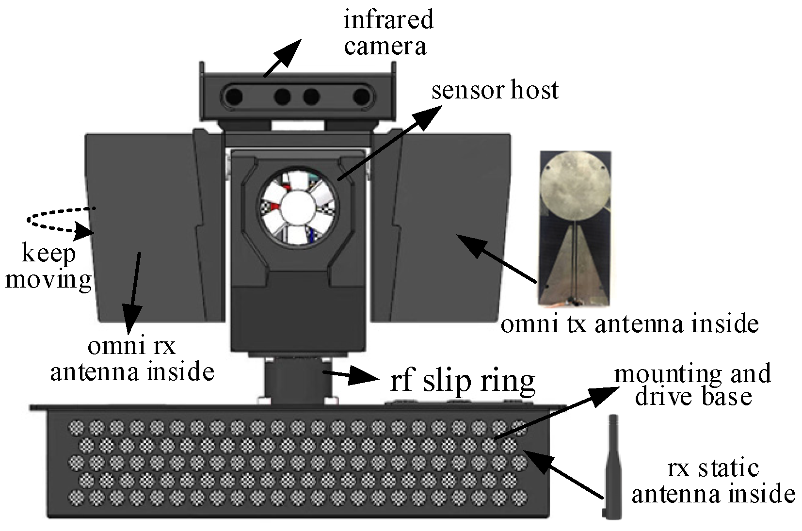
3. Design of the Sensor Hardware System

In order to verify the simulation model, signal-processing algorithms, and workflow in scenario experiments, for this paper, we designed an RF sensor hardware system with comprehensive consideration of cost, size, power consumption, and performance. Figure 5 presents the overall structure of this designed sensor system, which is capable of both autonomous transmission and reception. In this structure, the d r i v e   b a s e includes a power supply battery, a slip ring-driven motor, and a stationary receiving antenna, which helps eliminate frequency offsets between independent transceivers. The s e n s o r   h o s t , which is responsible for data processing, is connected to the d r i v e   b a s e via r f _ s l i p _ r i n g , which functions as the transmission channel for RF, power, and control signals between the moving and stationary components. Its two wings are each equipped with an omnidirectional antenna: one for transmitting the detection waveform and the other for constructing a SAR antenna via rotational motion with a stationary receiving antenna. The sensor core control board is mounted on the body between the two antennas, and the overall architecture is depicted in Figure 6. The system is composed of three parts: the antenna unit, the RF front end, and the core control unit. The antenna unit employs a 1-transmit, 2-receive omnidirectional broadband antenna, covering a frequency range from 600   M H z to 6000   M H z . Collaborative positioning RF sensors are often mounted on outdoor mobile platforms like unmanned vehicles and drones, necessitating a compact size and low power consumption. To meet these requirements, for this paper, we designed an RF front-end solution based on the ADRV9009 RF transceiver (Wuhan Qishengtong Technology Co., Ltd., Wuhan, China) integrated chip, which supports four independent communication links of 2-receive and 2-transmit channels. Compared with traditional superheterodyne RF front-end solutions, this chip offers inherent advantages in terms of size, cost, and power consumption, with a compact size of only 10   m m × 10   m m × 1.6   m m , making it ideal for embedded designs in various circuit boards.
The core control unit adopts Xilinx’s heterogeneous architecture, ZYNQMP FPGA, consisting of resource-rich FPGA programmable logic (PL) and four ARM architecture A53 hard-core PSs. The PL side focuses on high-speed parallel signal processing, including transmission link signal processing, receive filtering, matched filtering, dual-channel phase difference calculation, and SAR-like angle estimation, as well as the azimuth angle of arrival and distance computation. The PS side is responsible for peripheral interface control and the implementation of complex logic algorithms, such as overall logic, timing control, position estimation, and the realization of Kalman-based target-tracking algorithms. The PL and PS communicate through the high-speed AXI interconnect bus (Wuhan Qishengtong Technology Co., Ltd., Wuhan, China), collaboratively handling the processing and control of both internal and external sensor data and instructions.
Notably, considering the relative positioning requirements in future multi-node work scenarios, in our FPGA design, we employ modular node interface logic and assign each node a unique identification sequence (IP address or pseudo-random code). Combined with a code division multiple access (CDMA) scheme, the system ensures conflict-free access for multiple nodes. As the number of nodes increases, the system can support additional node identification and resource allocation through dynamic partial reconfiguration or remote updates to BRAM contents. The system also leverages dual-port BRAM and DMA mechanisms to optimize data access efficiency, enhancing the processing speed. Moreover, we assess the utilization of FPGA resources (such as LUTs, FFs, and BRAMs) and ensure sufficient expansion margins, ensuring that the system can be deployed effectively in medium- to large-scale work configurations.
Based on the above hardware foundation, distance and angle measurements between the sensor and neighboring nodes are achieved through wireless transmission and reception by designing reasonable waveforms and timing controls, enabling relative position estimation among the collaborative nodes. The ADRV9009 chip (Middlesex County, MA, USA) in the hardware offers stable signal processing at 245.76   M s p s , a frequency aligned with 5G communication systems, ensuring compatibility with the existing infrastructure while enhancing the sensor’s operational value and efficiency. As a result, we set the symbol rate of the baseband signal to b = 245.76   M s p s , and the theoretical minimum time resolution for wireless measurement is one sampling interval, where t c = 1 / ( 245.17 × 10⁶). Given the speed of light at c = 3 × 10⁸ m/s, the theoretical distance resolution is calculated as R = c / 2 b = 0.61   m . Distance measurement resolution can be further enhanced through super-resolution software algorithms. To evaluate the real-world performance of the localization algorithm implemented on the sensor developed from this research, the following section presents the results of testing in both an anechoic chamber and on unmanned vehicles in outdoor fields, where real data collection and processing can be conducted in a 2D space under controlled conditions.

4. Experiments and Discussions

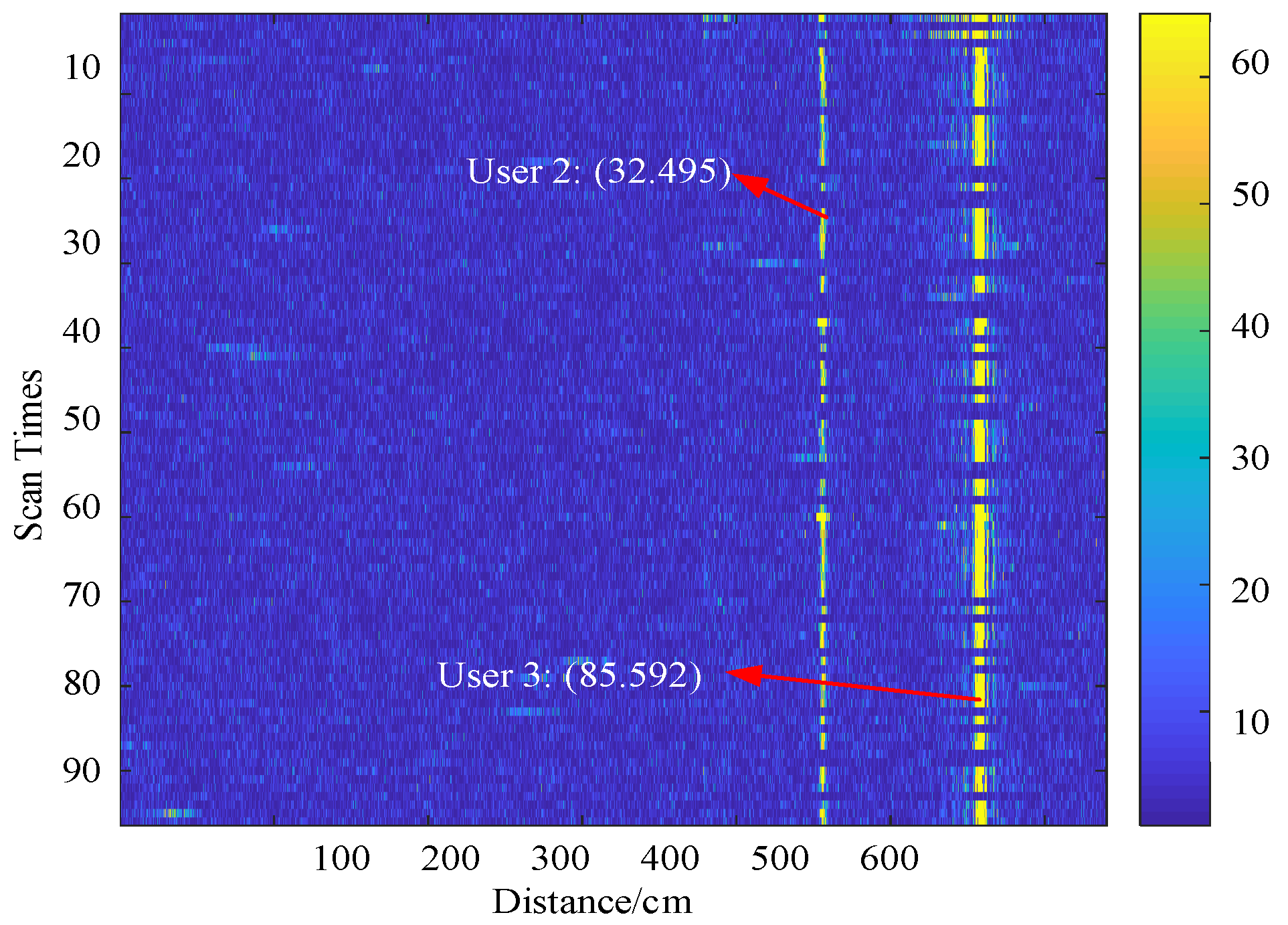
4.1. Microwave Anechoic Chamber Experiment

To validate the direction-finding performance of the ASAR algorithm and the ranging performance of the LLCR algorithm, the authors of this study first set up a scenario in an anechoic chamber with minimal multipath interference, constructing the first-generation prototype shown in Figure 7. The prototype consists of the following main components. Circle 1 represents the experimental turntable, which is fixed to the table at its base. The turntable’s disc carries s e n s o r   h o s t   u s e r 1 and a receiving antenna, marked as Circles 5 and 3, respectively. As the disc rotates, the antenna becomes a moving, rotating element forming a larger receiving aperture, as illustrated in Figure 4a. The turntable, driven by a high-precision stepper motor, rotates u s e r 1 according to predefined instructions, with a control accuracy of approximately 0.01 ° , meeting the requirements for practical testing. Circle 2 represents another static receiving antenna of u s e r 1 , which is connected to the host’s receive channel 2 via a feedline that passes through the r f   s l i p   r i n g inside Circle 1. Circles 4 and 6 represent the transmitting antenna and receiving antenna of another sensor, u s e r 2 , respectively.
Since the sensor’s RF front end utilizes an integrated RF transceiver structure, it offers wideband capabilities, with the RF ranging from 75   M H z to 6000   M H z . For the experiment, a fourth-generation (4G) omnidirectional antenna with a gain of approximately 0   d B i was selected, with the RF center frequency set to 910   M H z , a transmit power of 0   d B m , and a receiving digital manual gain control (MGC) of 30   d B . The transmitted waveform sequences included a Frank sequence and a CAZAC sequence, with both sampling points set to 1024 . A Cartesian coordinate system was established, as illustrated in Figure 7, with the rotation center of the turntable as the origin and the horizontal leftward direction as the reference zero point. With the floor of the anechoic chamber being covered with absorbing material and the limited space preventing continuous movement, three measurement points, A , B , and C , were selected along the x-direction for the angle measurement experiment. Using a laser and protractor, the angles between u s e r 1 and points A , B , and C were measured in the custom coordinate system, yielding values of 90 ° , 80 ° , and 61 ° , respectively.
Figure 8a–c presents the multipath energy distribution across spatial angles derived from sensor u s e r 1 , applying the ASAR algorithm to process the waveform received from u s e r 2 at locations A , B , and C , respectively. It can be observed that each azimuth spectrum exhibits a clear main beam, with an amplitude that is notably higher than the sidelobes. The angle at the peak is used as the estimated incoming wave direction, with an error within 0.6 ° compared to the actual angle. For instance, when u s e r 2 is positioned at 90 ° , the sensor detects a prominent peak in the azimuth spectrum, with a value of 386.80 , which is approximately six times that of the second-highest peak of 60.5 . The measured arrival angle is 90.57 ° , resulting in an error of 0.57 ° , effectively confirming the exceptional performance of this algorithm when measuring a single direction of arrival.
To validate the ASAR algorithm’s performance in multi-target azimuth detection, sensors u s e r 2 and u s e r 3 were placed at points A   90 ° and C   61 ° in the anechoic chamber experimental setup depicted in Figure 7. This experiment validates sensor u s e r 1 ’s ability to detect the azimuths of both u s e r 2 and u s e r 3 , with the detection results presented in Figure 8d. The figure reveals two distinct peak values. Through azimuth spectrum analysis exceeding the detection threshold, the identified peaks corresponded to 60.63 ° and 90.47 ° , respectively, with angular deviations of 0.37 ° and 0.47 ° from the preset reference angles. The measurement errors were maintained within 0.5 ° , demonstrating commendable azimuth measurement performance. In the above azimuth measurement spectrum, the minor peaks that were observed in various directions, aside from the highest peak from the direct path, arose from the fixed, immovable circular motorized turntable in the anechoic chamber used for the experiment. The metallic irregularities of the turntable induced partial wave reflections and diffractions, resulting in small multipath peaks in various directions. However, their low energy rendered these effects negligible, meaning that they exerted minimal influence on the final measurement accuracy.
To verify the distance detection performance of the sensor, in the setup depicted in Figure 7, u s e r 2 and u s e r 3 were arranged along the y-axis, with their straight-line distances from u s e r 1 measured using a tape measure as 5   m and 6   m , respectively. Figure 9 presents the outcomes of 100 consecutive distance detections for u s e r 1 , with the x-axis representing the detection distance in centimeters, the y-axis indicating the number of detection scans, and the pixel values reflecting the strength of the received signal. It can be seen from the figure that during 100 consecutive measurements, two distinct neighboring node-reflected echo signals were detected, which were found to be located at 495   c m and 592   c m after distance calculation, respectively, with signal strengths ranging between 50 and 60 . The deviations from the preset distance values were only 5 8   c m , less than 0.1   m . The detection results for u s e r 3 exhibited a fluctuation of 5   c m , which was likely attributable to its proximity to the motorized turntable, resulting in multipath effects that induced variations in the measurements. Overall, the LLCR algorithm exhibited high accuracy and stability in distance detection, meeting the requirements for practical applications.
An analysis of the azimuth and distance measurement results from the first-generation prototype in the anechoic chamber demonstrates that the proposed algorithms can accurately measure the positions and azimuths of neighboring nodes in a navigation signal-denied environment, supporting its further integration, iterative upgrades, and refinement for outdoor experimental validation. The next phase involves conducting functional and performance testing of the upgraded second-generation sensor nodes within a field environment.

4.2. Field Experiment

Prior to evaluating the performance of the developed collaborative localization sensor in field tests, the authors iteratively upgraded the second-generation collaborative perception sensor, shown in Figure 10, building upon the anechoic chamber verification of the first-generation prototype and the design scheme in Figure 5. The lower left of Figure 10 illustrates the core processing board of the sensor, featuring the ZYNQMP heterogeneous processing chip from Xilinx (San Jose, CA, USA) as its core control unit, which combines FPGA-based parallel acceleration with the flexible, complex programming capabilities of an ARM processor. The RF module utilizes the ADRV9009 chip from Analog Devices Inc. (Middlesex County, MA, USA), the detailed specifications of which are provided in Section 3.
Now, we will introduce the operational framework of the sensor designed in this paper. The sensor operates in three distinct modes: (1) Desktop Mode: Illustrated in the upper left corner of Figure 10, this mode is primarily designed for indoor positioning, testing, and debugging tasks. (2) Unmanned Vehicle-Mounted Mode: Shown in the upper left corner of Figure 11, this mode is primarily used for outdoor 2D collaborative positioning. In this setup, the sensor collaborates with the unmanned vehicle to autonomously plan its paths and execute the corresponding collaborative tasks. (3) Drone-Mounted Mode: Depicted on the right side of Figure 10, this mode is intended for outdoor 3D collaborative positioning tasks. In this configuration, the drone follows specified paths and performs actions while adjusting its posture in 3D space via remote control. This enables verification of the sensor’s 3D detection performance and allows for further optimization by analyzing how uncertain factors, such as drone jitter and postural changes, affect the detection results.
Next, the following sections of this paper focus on evaluating the sensor’s 2D spatial collaborative detection performance in the unmanned vehicle-mounted mode. Figure 11 shows the field experiment environment. The experiment took place in a vast U-shaped open area within the campus, serving as a model for 2D spatial proximity node position awareness. Prior to the experiment, the three sensors were positioned on stools 80   c m above the ground for pre-experiment condition checks and calibration, as illustrated in the lower-left corner of Figure 11. Owing to the limited number of unmanned vehicles available, during the experiment, u s e r 1 remained stationary on the stool. U s e r 2 , being loaded onto the unmanned vehicle, moved slowly along the green route marked in the figure, then continued straight after making a turn, as shown in the upper-left corner of Figure 11, while u s e r 3 , mounted on a flatbed trailer, was manually pulled along the red route marked in the figure, as illustrated in the lower-right corner of Figure 11.
Figure 12 presents the detection results of the outdoor experiment. Within the experimental site, the space between u s e r 1 and u s e r 3 was an unobstructed line-of-sight (LoS) environment, while u s e r 2 ’s path, encountering occasional tree trunks, can still be regarded as an open LoS condition. To compare the experimental results, each sensor module was equipped with a global positioning system (GPS) module. During the experiment, u s e r 1 remained stationary, while u s e r 2 and u s e r 3 moved along predetermined trajectories. The detection results of u s e r 1 were exported and compared with the motion trajectories recorded by the GPS modules to validate the sensor’s detection performance. To facilitate comparison with the GPS data, the horizontal axis represents the target’s position relative to u s e r 1 , while the vertical axis indicates its elevation. The red and green lines in the figure represent the detection of the relative position information data between u s e r 1 and the neighboring u s e r 3 and u s e r 2 , respectively. The black and blue lines correspond to the position data relative to u s e r 1 , as obtained from the GPS module. As shown, the relative position estimates of u s e r 1 to the neighboring u s e r 2 and u s e r 3 nodes closely match the data obtained from the GPS, achieving the goal of anchor-free relative position estimation and demonstrating that the low-latency ranging and high-accuracy, ambiguity-free azimuth estimation algorithms proposed in this paper are functioning correctly. The first half of u s e r 2 ’s measurement data aligns well with the GPS data, but significant fluctuations in the second half after the turn, which may be caused by tree trunk obstructions between u s e r 1 and u s e r 2 , indicate that the algorithm still has room for improvement in non-line-of-sight (NLOS) optimization.
Next, we will discuss the algorithm’s detection performance in terms of its specific direction-finding and ranging capabilities. This discussion begins with an analysis of its direction-finding accuracy. The data from the three test nodes obtained from the GPS module were converted into azimuth information relative to u s e r 1 for u s e r 2 and u s e r 3 . These values serve as a reference for comparison with the sensor’s own measurement data, determining the actual angular measurement error. Further statistical calculations were conducted, resulting in the cumulative distribution function (CDF) of the ASAR angle measurement algorithm, as shown in Figure 13. As can be observed in the figure, the azimuth measurement error fluctuated within a certain range, with minimal overall variation and a mean value basically within 2 ° . Techniques such as clustering, mean filtering, and Kalman filtering can further improve azimuth measurement accuracy, providing a precise angular reference for overall relative position measurements. Notable deviations in certain angular data during the angle measurement can primarily be attributed to two factors: the slight trajectory deviations of the flatbed during towing and a certain level of multipath superposition caused by the partial tree trunk obstructions in the latter segment of u s e r 2 ’s trajectory.
Furthermore, we analyzed the distance detection performance of the method proposed in this paper. The GPS module data from the three test nodes were processed to generate standard reference distances for u s e r 2 and u s e r 3 relative to u s e r 1 , compared with the actual measured distances exported from u s e r 1 . Figure 14 illustrates the CDF of the distance measurement error from the field experiments, where the horizontal axis represents the error range, while the vertical axis represents the corresponding CDF values. The red solid line and black dashed line indicate the distance errors in the y- and x-directions, respectively. All distance errors, calculated using the Euclidean distance method, demonstrated consistent stability, with a mean value of approximately 28   c m . Advanced processing techniques, including Kalman filtering and mean filtering, were effective in further reducing measurement inaccuracies.
Overall, during the measurement process, considerable errors occurred in certain locations, primarily due to multipath interference from surrounding tree trunks and the ground, despite the relatively open nature of the experimental field. Additionally, the lateral oscillations of the manually towed flatbed further contributed to these errors. To address these challenges, future improvements could involve the adoption of fully automated path planning for vehicles, which would minimize the uncertainties introduced by human factors.

5. Conclusions

To address the challenges of GNSS interference in contested environments or an inability to obtain high-quality navigation signals in complex urban canyon scenarios, this paper presents the design of a high-precision real-time sensor for anchor-free collaborative positioning, which operates independently of GNSS signals through wireless detection between adjacent nodes. First, we introduce a positioning algorithm that combines LLCR-based ranging and ASAR-based direction finding for enhanced node localization. Based on this, we develop the first-generation prototype of the sensor. Next, we evaluate the direction-finding and distance-detection capabilities of this prototype in an anechoic chamber, with experimental results achieving the design goals, thereby demonstrating a preliminary ability for neighboring node-position sensing. Finally, by advancing toward greater integration and unification, the sensor was upgraded to a second-generation prototype, which underwent comprehensive performance evaluations in field environments. The test results reveal a single detection time within 1   μ s and a detection error within 0.4   m , significantly enhancing the robustness of collaborative positioning systems for unmanned vehicles while reducing infrastructure requirements and system complexity and further optimizing energy efficiency and operational effectiveness. The detection accuracy can be further improved through Kalman filtering, clustering, median filtering, and other algorithms. The second-generation sensor has undergone testing exclusively in open, LoS environments. Future developments will focus on enhancing the next-generation prototype’s multipath resilience in NLOS scenarios, achieving a more compact and streamlined design and enabling precise 3D spatial positioning, as well as facilitating seamless integration with other operational systems. In addition, while the current prototype involves a limited number of nodes, the proposed architecture remains highly scalable and adaptable to broader deployment scenarios. Further validation and performance evaluation of multi-node systems will also be explored in our future research.

Author Contributions

Conceptualization, D.B., X.L. and L.Z.; methodology, D.B., X.L. and L.Z.; software, X.L.; validation, D.B., X.L. and L.Z.; formal analysis, D.B., X.L., L.Z. and C.Y.; investigation, D.B., X.L. and L.Z.; resources, D.B. and L.Z.; data curation, X.L., Y.C. (Yongqiang Cui) and L.B.; writing—original draft preparation, D.B., X.L. and L.Z.; writing—review and editing, D.B., X.L., L.Z., C.Y., Y.C. (Yongqiang Cui), L.B. and Y.C. (Yunhao Chen); visualization, L.Z. and X.L.; supervision, D.B.; project administration, D.B. and C.Y.; funding acquisition, D.B., C.Y. and Y.C. (Yunhao Chen). All authors have read and agreed to the published version of the manuscript.

Funding

This research was funded in part by the National Nature Science Foundation of China under grant numbers 62201621 and 62401499, the Innovative Research Group Project of the Natural Science Foundation of Hubei Province under grant number 2024AFA030, the Foundation of Yunnan Key Laboratory of Unmanned Autonomous Systems (grant number 202408YB09), and the Fundamental Research Funds for the Central Universities of the South-Central MinZu University (Grant No. CZQ24003).

Data Availability Statement

All of the required data are available in the manuscript. We do not have any data to share.

Acknowledgments

The authors thank all colleagues who participated in this work. The authors would like to express their gratitude to the anonymous reviewers and the editor for their constructive comments on this paper.

Conflicts of Interest

The authors declare no conflicts of interest.

Abbreviations

The following abbreviations are used in this manuscript:
GNSSGlobal navigation satellite system
RFRadio frequency
FPGAField-programmable gate array
LLCRLow-latency collaborative ranging
SoCSystem-on-chip
AOAAngle of arrival
RSSReceived signal strength
TOATime of arrival
TDOATime difference of arrival
RTTRound-trip time
3DThree-dimensional
DTMDigital terrain model
WSNsWireless sensor networks
SFOSunflower optimization algorithm
DV-HopDistance vector-hop
ASARAnalogous synthetic aperture radar
2DTwo-dimensional
IDsIdentifications
SNRSignal-to-noise ratio
IPInter protocol
PSProcessing system
CFOCarrier frequency offset
PLProgrammable logic
4GFourth generation
MGCManual gain control
LoSLine-of-sight
GPSGlobal positioning system
NLOSNon-line-of-sight
CDFCumulative distribution function

References

  1. Win, M.Z.; Shen, Y.; Dai, W. A Theoretical Foundation of Network Localization and Navigation. Proc. IEEE 2018, 106, 1136–1165. [Google Scholar] [CrossRef]
  2. Dai, W.; Shen, Y.; Win, M.Z. Energy-Efficient Network Navigation Algorithms. IEEE J. Sel. Areas Commun. 2015, 33, 1418–1430. [Google Scholar] [CrossRef]
  3. Liu, Z.; Dai, W.; Win, M.Z. Mercury: An Infrastructure-Free System for Network Localization and Navigation. IEEE Trans. Mob. Comput. 2018, 17, 1119–1133. [Google Scholar] [CrossRef]
  4. Tian, X.; Song, Z.; Jing, B.; Zhang, Y.; Yu, T.; Wang, X. HiQuadLoc: A RSS Fingerprinting Based Indoor Localization System for Quadrotors. IEEE Trans. Mob. Comput. 2017, 16, 2545–2559. [Google Scholar] [CrossRef]
  5. Guo, Q.; Zhang, Y.; Lloret, J.; Kantarci, B.; Seah, W.K.G. A Localization Method Avoiding Flip Ambiguities for Micro-UAVs with Bounded Distance Measurement Errors. IEEE Trans. Mob. Comput. 2019, 18, 1718–1730. [Google Scholar] [CrossRef]
  6. Liu, Y.; Wang, Y.; Wang, J.; Shen, Y. Distributed 3D relative localization of UAVs. IEEE Trans. Veh. Technol. 2020, 69, 11756–11770. [Google Scholar] [CrossRef]
  7. Wang, Y.; Wu, Y.; Shen, Y. Cooperative Tracking by Multi-Agent Systems Using Signals of Opportunity. IEEE Trans. Commun. 2020, 68, 93–105. [Google Scholar] [CrossRef]
  8. Liu, J.; Hu, G. Relative Localization Estimation for Multiple Robots via the Rotating Ultra-Wideband Tag. IEEE Robot. Autom. Lett. 2023, 8, 4187–4194. [Google Scholar] [CrossRef]
  9. Cai, Y.; Shen, Y. An Integrated Localization and Control Framework for Multi-Agent Formation. IEEE Trans. Signal Process. 2019, 67, 1941–1956. [Google Scholar] [CrossRef]
  10. Li, X.; Ma, K.; Wang, J.; Shen, Y. An Integrated Design of Cooperative Localization and Motion Control. In Proceedings of the 2019 IEEE International Conference on Communications, Shanghai, China, 11–13 August 2019. [Google Scholar] [CrossRef]
  11. Li, X. Collaborative Localization with Received-Signal Strength in Wireless Sensor Networks. IEEE Trans. Veh. Technol. 2007, 56, 3807–3817. [Google Scholar] [CrossRef]
  12. Conti, A.; Guerra, M.; Dardari, D.; Decarli, N.; Win, M.Z. Network Experimentation for Cooperative Localization. IEEE J. Sel. Areas Commun. 2012, 30, 467–475. [Google Scholar] [CrossRef]
  13. Niculescu, D.; Nath, B. Ad Hoc Positioning System (APS) using AOA. In Proceedings of the Twenty-Second Annual Joint Conference of the IEEE Computer and Communications Societies, San Francisco, CA, USA, 30 March–3 April 2003. [Google Scholar] [CrossRef]
  14. Bartoletti, S.; Dai, W.; Conti, A.; Win, M.Z. A Mathematical Model for Wideband Ranging. IEEE J. Sel. Top. Signal Process. 2015, 9, 216–228. [Google Scholar] [CrossRef]
  15. Wennervirta, J.; Wigren, T. RTT Positioning Field Performance. IEEE Trans. Veh. Technol. 2010, 59, 3656–3661. [Google Scholar] [CrossRef]
  16. Tan, A.H. A New Distance Metric Based on Bias-Variance Tradeoff for Wireless Fingerprinting. IEEE Trans. Instrum. Meas. 2024, 73, 2532710. [Google Scholar] [CrossRef]
  17. Hayward, S.J.; van Lopik, K.; Hinde, C.; West, A.A. A Survey of Indoor Location Technologies, Techniques and Applications in Industry. Internet Things 2022, 20, 100608. [Google Scholar] [CrossRef]
  18. Zaarour, N.; Hakem, N.; Kandil, N. An Accurate Anchor-Free Contextual Received Signal Strength Approach Localization in a Wireless Sensor Network. Sensors 2024, 24, 1210. [Google Scholar] [CrossRef]
  19. Li, X.; Ban, B.; Yang, Y.; Jin, M. Localization of Networks on 3D Terrain Surfaces. IEEE Trans. Mob. Comput. 2022, 21, 1710–1722. [Google Scholar] [CrossRef]
  20. Rayavarapu, V.C.S.R.; Mahapatro, A. A Novel Range-Free Anchor-Free Localization in WSN Using Sun Flower Optimization Algorithm. In Proceedings of the 2021 Advanced Communication Technologies and Signal Processing (ACTS), Rourkela, India, 15–17 December 2021. [Google Scholar] [CrossRef]
  21. Aka, A.C.; Atta, A.F.; Keupondjo, S.G.A.; Oumtanaga, S. An Efficient Anchor-Free Localization Algorithm for all Cluster Topologies in a Wireless Sensor Network. Int. J. Comput. Commun. Control 2023, 18, 4961. [Google Scholar] [CrossRef]
  22. Shah, I.; Dohare, Y.; Yadav, D. A Modified Anchor Free Localization Technique for Wireless Sensor Network. EAI Endorsed Trans. Cloud Syst. 2020, 6, 166553. [Google Scholar] [CrossRef]
  23. He, W.; Cheng, R.; Mao, K.; Yan, K.; Wei, J.; Xu, Y. A Novel Anchorless Node Positioning Method for Wireless Sensor Network. J. Sens. 2022, 2022, 5385393. [Google Scholar] [CrossRef]
  24. IEEE 802.15.4a; IEEE Standard for Local and Metropolitan Area Networks—Part 15.4: Low-Rate Wireless Personal Area Networks (LR-WPANs)—Physical Layer (PHY) Specifications for Ultra Wideband (UWB). IEEE: New York, NY, USA, 2007. [CrossRef]
  25. Li, Y.; Zhang, Z.; Wu, L.; Dang, J.; Liu, P. 5G Communication Signal Based Localization with a Single Base Station. In Proceedings of the 2020 IEEE 92nd Vehicular Technology Conference, Victoria, BC, Canada, 4–7 October 2020. [Google Scholar] [CrossRef]
  26. Wang, W.; Yan, S.; Mao, L.; Guo, X. Robust Minimum Variance Beamforming with Sidelobe-Level Control Using the Alternating Direction Method of Multipliers. IEEE Trans. Aerosp. Electron. Syst. 2021, 57, 3506–3519. [Google Scholar] [CrossRef]
  27. Zhao, C.; Chen, Z.; He, C.; Xie, F.; Chen, X. A Hybrid Beam-Forming and Direction-Finding Method for Wind Direction Sensing Based on HF Radar. IEEE Trans. Geosci. Remote Sens. 2018, 56, 6622–6629. [Google Scholar] [CrossRef]
  28. Kim, J.S.; Lee, J.; Serpedin, E.; Qaraqe, K. Robust Clock Synchronization in Wireless Sensor Networks through Noise Density Estimation. IEEE Trans. Signal Process. 2011, 59, 3035–3047. [Google Scholar] [CrossRef]
  29. Mao, F.; Ma, H.; Jiao, Y.; Li, D.; Gao, Z. Analysis of the Research Status of Phase Interferometer Deblurring. In Proceedings of the 2021 IEEE International Conference on Artificial Intelligence and Industrial Design, Guangzhou, China, 28–30 May 2021. [Google Scholar] [CrossRef]
  30. Lu, L.; Li, Y.; Rizos, C. Virtual Baseline Method for Beidou Attitude Determination—An Improved Long-short Baseline Ambiguity Resolution Method. Adv. Space Res. 2013, 51, 1029–1034. [Google Scholar] [CrossRef]
  31. Li, Y.; Zou, X.; Liu, P.; Luo, B.; Pan, W.; Yan, L. Four-Element Array for GNSS Attitude Determination Using IRLS: An Improved Rounding of Long-Short Baseline Approach. IEEE Trans. Veh. Technol. 2020, 69, 4920–4934. [Google Scholar] [CrossRef]
Figure 1. Diagram of the LLCR ranging scheme.
Electronics 14 01667 g001
Figure 2. Block diagram of the LLCR IP logic circuit design.
Electronics 14 01667 g002
Figure 3. Two-way low-latency distance detection diagram.
Electronics 14 01667 g003
Figure 4. (a) Circular SAR; (b) signal model.
Electronics 14 01667 g004
Figure 5. Sensor design scheme.
Electronics 14 01667 g005
Figure 6. General block diagram of the sensor.
Electronics 14 01667 g006
Figure 7. First-generation prototype anechoic chamber: experimental scenario.
Electronics 14 01667 g007
Figure 8. (a) Anechoic chamber azimuth measurement results for a 90 ° preset point; (b) azimuth measurement results for an 80 ° preset point; (c) azimuth measurement results for a 61 ° preset point; (d) simultaneous detection results for 61 ° and 90 ° preset points.
Electronics 14 01667 g008
Figure 9. Anechoic chamber distance measurement results.
Electronics 14 01667 g009
Figure 10. Second-generation multi-modal sensor.
Electronics 14 01667 g010
Figure 11. Second-generation prototype: unmanned vehicle test environment.
Electronics 14 01667 g011
Figure 12. Unmanned vehicle sensor field-test results.
Electronics 14 01667 g012
Figure 13. Field experiment azimuth measurement error diagram.
Electronics 14 01667 g013
Figure 14. Field experiment distance measurement error diagram.
Electronics 14 01667 g014
Disclaimer/Publisher’s Note: The statements, opinions and data contained in all publications are solely those of the individual author(s) and contributor(s) and not of MDPI and/or the editor(s). MDPI and/or the editor(s) disclaim responsibility for any injury to people or property resulting from any ideas, methods, instructions or products referred to in the content.

