Article

Piezoelectric Polymer-Based Collision Detection Sensor for Robotic Applications †

1
Applied Research Laboratories, University of Texas, Austin, TX 78758, USA
2
College of Engineering, Auburn University, Auburn, AL 36849, USA
*
Author to whom correspondence should be addressed.
This paper is an extended version of our paper published in Wooten, J.M.; Bevly, D.M.; Hung, J.Y.,“Robust large-area piezoelectric polymer-based collision detection sensor,” 39th Annual Conferenceof the IEEE Industrial Electronics Society (IECON 2013 ), Vienna, Austria, 10–13 November 2013,pp. 3994–3999.
Electronics 2015, 4(1), 204-220; https://doi.org/10.3390/electronics4010204
Submission received: 2 November 2014 / Revised: 8 December 2014 / Accepted: 2 March 2015 / Published: 12 March 2015
(This article belongs to the Special Issue Flexible Electronics)

Abstract

:
The authors present a large area collision detection sensor utilizing the piezoelectric effect of polyvinylidene fluoride film. The proposed sensor system provides high dynamic range for touch sensation, as well as robust adaptability to achieve collision detection on complex-shaped surfaces. The design allows for cohabitation of humans and robots in cooperative environments that require advanced and robust collision detection systems. Data presented in the paper are from sensors successfully retrofitted onto an existing commercial robotic manipulator.

1. Introduction

Recent sensing work with polyvinylidene fluoride (PVDF) film based sensors includes tactile applications related to robotic skin for finger tips [1], large area coverage [2], stress sensing for shock wave measurements [3], deflection sensing [3], object identification [4], smart textiles [5] and power harvesting [6] to name a few. The use of PVDF for energy generation from nano generators [7] is particularly compelling. Advances in manufacturing processes have also increased viability of PVDF as a flexible and adaptable sensor solution for complex surfaces through MEMS based fabrications [8] as well as the use of organic transistors to create a highly sensitive pressure sensor [2]. More recently, nano structure work utilizing nano ribbons has been shown to drastically increase the charge coefficient characteristics of PVDF [9]. Further work with micro- and nano-structurization shows strong promise for flexible tactile sensation viability of PVDF [10].
The majority of PVDF sensing applications traditionally rely on either a film membrane based strain sensation [11] or film on rigid substrate pressure sensation [2]. Both of these methods present challenges when applied to collision detection against typical robotic manipulator structures, which require sensing over large surface areas, over complex shapes, and a large range of impact forces. The membrane approach has practical shortcomings for large-area and high-impact applications because of inherent physical limitations (e.g., puncture of membrane) and a high level of design complexity for large-area sensor applications and networks. Pressure based designs require more complex electronics and construction to achieve flexibility because of the low signal response and need for a stiff substrate to achieve pressure dynamics.
In this paper, a novel sensor design is suggested utilizing a flexible substrate that allows the PVDF film to operate in a pseudo-membrane configuration, as shown in Figure 1a. Complex environments associated with modern robotics require tactician for control feedback, safety concerns, and perception to name a few [12]. The primary concern of the presented sensor design is safety and risk mitigation for complex environment as such the new sensor design can achieve high dynamic range, uses simplified electronics, and can be robustly applied over a variety of surface shapes. Sensor robustness means that the sensor can operate in a wide variety of environments including, but not limited to high and low impacts, non-uniform and complex surfaces, mobile and stationary systems, and human and non-human inhabited environments. The proposed sensor construction allows for complex shape and non-planar surface applications. The design is intended for safety and control applications related to human-robotics interaction in cooperative environments, arm autonomy in high degree-of-freedom (DOF) arms in changing scenarios, and technology redundancy to minimize risk related to collision. Current safety standards limit the amount of force that a robot can impart to a human being as 150 N [13]. The proposed sensor provides a dynamic sensing range of 5 N to greater than 200 N in an effort to detect a state of collision before significant force has been imparted to the object.

2. Design Methodology

The sensor’s mechanical structure, materials, physical properties, and electronic instrumentation are explained here. Additionally, the key design considerations are discussed.

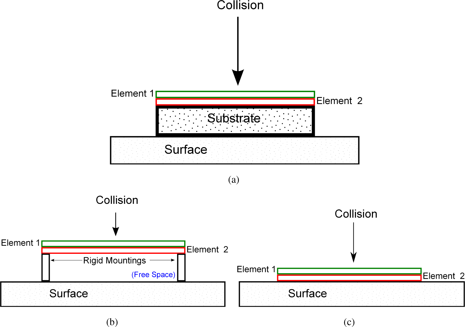
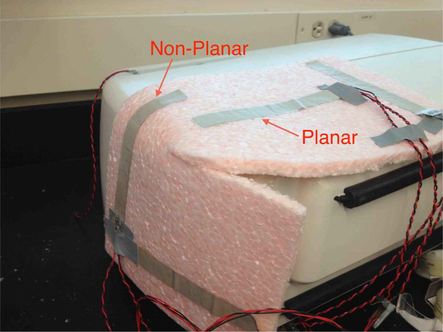
2.1. Materials and Structures

PVDF is a piezoelectric and pyroelectric polymer commercially available in thin (<0.1 mm) sheets. Commercial uses of PVDF include, but are not limited to force sensors, accelerometer applications, high-frequency resonators, and deflection sensing [3]. Piezoelectric PVDF film is created from homopolymer PVDF sheets that are stretched, heated and simultaneously poled by application of a high electric field across the film [14]. The stretching and heat annealing processes align the polymer chains within the PVDF, and the high electric field orients the dipoles of the chains to create polarization in the film [14]. Poling the film enables the polymer to generate charge when stressed by heat or physical stress because tensile stress in the film causes the dipoles to flip, creating a charge gradient that generates an electrical displacement. The piezoelectric and pyroelectric effects of the polymer do not degrade over time (< 1% of original value) insuring longterm reproducibility of sensations as long as the material is kept below approximately 90°C depending on PVDF construction. (At high temperature, the poles of the polymer become randomly oriented, eliminating the charge gradient [15].)
The proposed collision sensor is constructed of two PVDF film elements oriented with poles out of phase, adhered to a flexible elastic compressible substrate. The trilayer sensor is attached to the targeted surface, shown in Figure 1a. Element 1 and Element 2 represent the two PVDF film elements. In contrast, diagrams for traditional membrane and pressure based sensing are included and explained in the following subsection as Figure 1b,c, respectively.

2.1.1. Sensor Structures Using PVDF Film

Physical structures of traditional rigidly mounted membrane stress sensation-based and pressure sensation-based polyvinylidene fluoride (PVDF) film sensors are illustrated in the following figures and descriptions. The Rigid Construction shown in Figure 1b requires free space for diaphragm deflection and rigid mountings in order to achieve dynamic sensing range. This creates issues requiring specialized construction for applications and limitation in sensor and surface curvature.
The pressure sensation-based construction, Figure 1c, eliminates the need for rigid mountings and free space of the membrane; however, the Pressure Construction sensor output of strain due to pressure is much lower yielding more complex and specialized electronics. The pressure based construction also requires a very rigid surface and/or substrate to generate pressure transduction.
In the proposed structure, a collision stimulus deforms, or compresses, the elastic substrate due to localized compression and creates a resulting mechanical strain on the PVDF film elements, similar to a rigid membrane. The elastic substrate should be chosen to maximize the linear stress strain response and also to minimize total sensor size for manufacturing and application concerns. The trilayer pseudo-membrane approach using PVDF and an elastic substrate is uniquely suited to large area coverage because large PVDF sensing elements are easily constructed, the elastic substrate can be made of polyurethane foams and other commercially available sufficiently compressible and elastic materials with a Young’s Modulus lower than that of PVDF elements provided in Table 1, and the sensor is not limited to planar surfaces because the pseudo-membrane approach creates stress from localized substrate compression and not film strain as in the rigid membrane approach.

2.2. Sensing and Instrumentation

2.2.1. Piezoelectric Effect
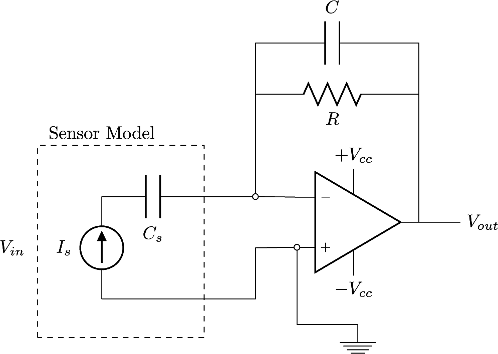
The proposed sensor utilizes the piezoelectric effect of PVDF thin films to create sensation over a surface. The tactile element transduces experienced stress to an electrical displacement, D, which is the charge density of the film surface, Q/A. The electrical displacement has three additive components, consisting of pyroelectric, piezoelectric, and dielectric effects [16]:
D = p Δ T + d j k X j k + ε E
The pyroelectric charge is a function of the change in temperature (ΔT) times pyroelectric charge coefficient (p), the piezoelectric charge is a relation of stress applied in Cartesian direction (Xjk) with the corresponding piezoelectric charge coefficient (djk), and the charge related to electric dipole moment is calculated by electric field (E) times the permittivity of the material (ε). For collision sensing, the desire is for electrical displacement, D, to be a purely piezoelectric response, djkXjk. The electric field, E, can be minimized by proper design of the charge amplifier sensor interface, which is discussed below in Section 2.2.2. The pyroelectric component, ΔT, can be canceled because of phase orientation of the bilayer sensing element and common mode signal filtering; therefore, the pyroelectric and dielectric effects fall away reducing Equation (1) to the desired purely piezoelectric displacement in Equation (2).
D = d j k X j k = d 31 X 31 + d 32 X 32 + d 33 X 33
The stress vector, Xjk, in Equation (2) represent tensile stress in length, width, and thickness directions respectively. Due to high compressibility of the substrate relative to the PVDF film, strain related to compression, X33 is approximately 0. The piezoelectric constants corresponding to tensile stress in the width and length, d31 and d32 respectively in Cartesian coordinate representation. The Cartesian coordinate system in this paper uses the following equivalent relations interchangeably, {x, y, z} = {1, 2, 3} = {width, length, thickness}. Where z+ is normal going away from the sensor and (x, y) are parallel. xxx, yyy, and zzz, are equal. Therefore, the electrical displacement of the sensor is proportional to the total transverse and longitudinal stress in the film created by the collision reducing Equation (2) further to the reduced representation of the sensor electrical displacement in Equation (3).
D = d 31 ( X 31 + X 31 )
The applicable material properties of PVDF film are shown in Table 1 are provided by the film manufacturer, Measurement Specialties.

2.2.2. Electronics

The electronics interface for the PVDF film elements requires high signal gain, low output impedance, high input impedance, low time constant to capture 1 Hz collisions, and a minimization of the electric field effect of the sensor. A charge amplifier is used to minimize effects of sensor and line capacitance by minimizing input impedance, to minimize electric field by grounding sensor electrode, and because the elements act as a current source. The circuit, shown in Figure 2, acts as a single pole high-pass filter with a bleed resistor added in parallel to create a low enough cutoff frequency to properly detect physical interaction, in the 1 Hz to 1 kHz range [15]. The transfer function is given by:
H ( s ) = V o u t ( s ) V i n ( s ) = s R C s s R C + 1
The system can be properly designed to yield a low enough corner frequency calculated from:
f c = 1 2 π R C
which gives the desired low end frequency range. The signal is then low-pass filtered with a chosen high cut off frequency to attenuate unwanted high frequency noise. Finally, the signal is conditioned for input to the analog to digital converter (ADC). The charge amplifier allows for positive and negative voltage range of +/− Vcc to create the large dynamic range needed for collision detection.

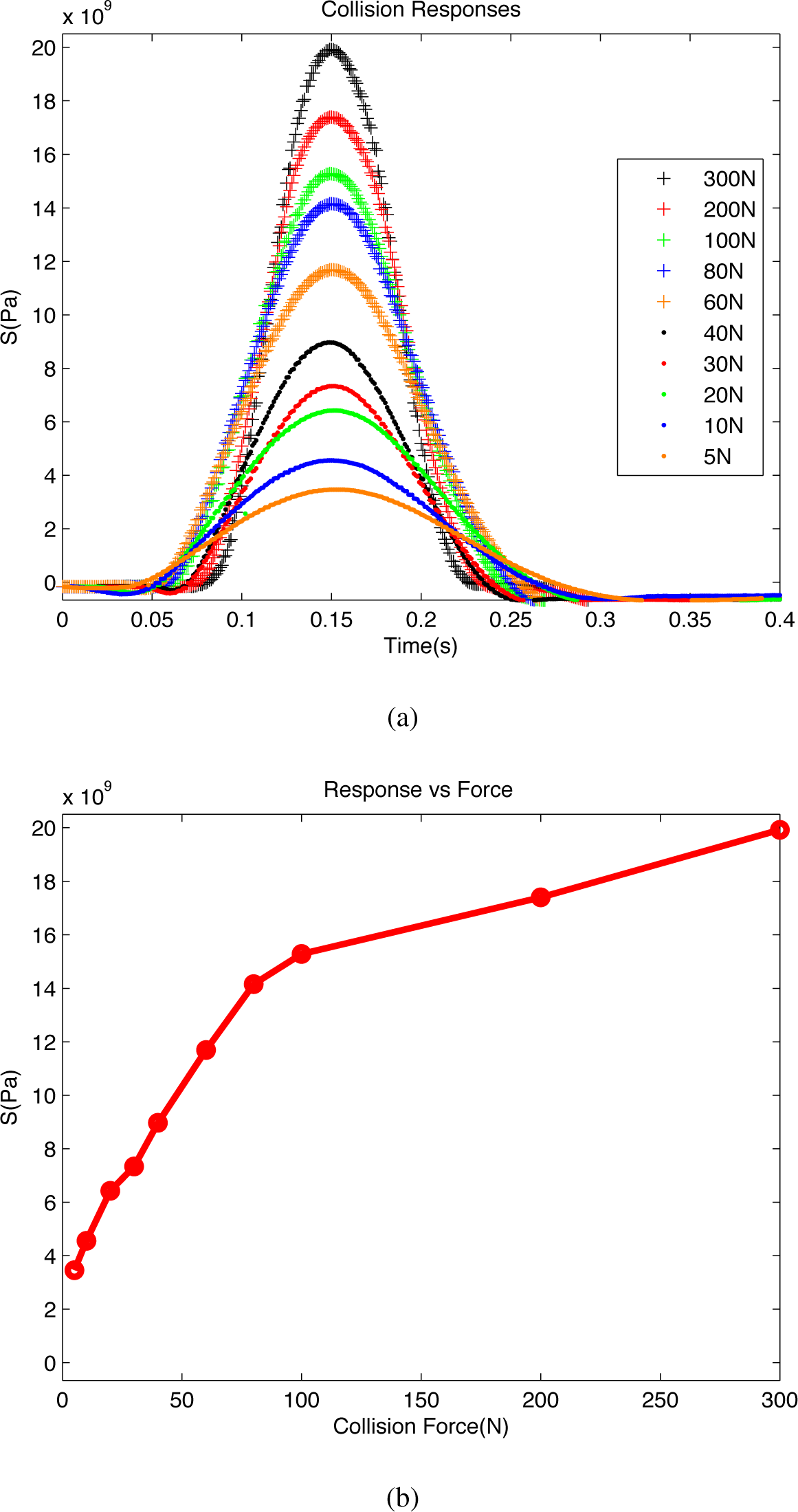
2.2.3. Strain Modeling

For modeling purpose, the area of concern is restricted to the local frame of the collision and the stress-strain response is approximately linear and the substrate will be treated as a continuum. The film stress from Equation (2) is equal to the stress of the surface of the substrate, assuming a perfect adhesive bond and negligible effects of film sensor on substrate stress characteristics,
σ ¯ = [ T e 1 T e 2 T e 3 ] = [ σ 11 σ 12 σ 13 σ 21 σ 22 σ 23 σ 31 σ 32 σ 33 ] = [ σ x τ x y τ x z τ y x σ y τ y z τ x z τ y z σ z ]
By defining the Cauchy stress tensor ( σ ¯) of the substrate, Equation (6), in terms of the normal and shear stresses, {σx, σy, σz} and {τxy, τxz, τyz}, Xjk in Equation (2) can be replaced by the stress vector, Te3, of the material surface resulting in Equation (7).
D = d 31 ( τ x z + τ y z )
From Equation (7), the stress contributing to the piezoelectric effect of the film is the orthogonal shear stress experienced by the substrate at the collision point. Therefore, the sensor dynamic range is dependent on the shear and normal stress characteristics of the chosen substrate. Using the shear modulus of elasticity (G) to relate shear strain to shear stress Equation (8), Young’s Modulus of the substrate (E) to relate normal strain to normal stress Equation (8),
G = τ x z γ x z E = σ z ϵ z
along with the geometric representation of strain, Equation (9),
ϵ i j = 1 2 ( δ i j o + δ j i o )
and Cauchy’s strain tensor ( ϵ ¯ ¯) Equation (10),
ϵ ¯ ¯ = [ ϵ 11 ϵ 12 ϵ 13 ϵ 21 ϵ 22 ϵ 23 ϵ 31 ϵ 32 ϵ 33 ] = [ ϵ x γ x y 2 γ x z 2 γ y x 2 ϵ y γ y z 2 γ x z 2 γ z y 2 ϵ z ]
and assuming the substrate is under compression locally where δx = δy = 0, δz ≠ 0, and xo, yo are known static quantities, Equation (7) is transformed to Equation (15), shown in Equations (11)(14) using the relations Equation (8) through Equation (10):
τ x z + τ y z = G ( γ x z + γ y z ) = G ( 2 ϵ x z + 2 ϵ y z )
= G ( δ z x o + δ z y o )
= G z o ( y o + x o ) x o y o ( ϵ z )
= G E z o ( y o + x o ) x o y o ( σ z ) = S
Compressive stress, σz, is a monotonically increasing and directly proportionate function of the force of the collision normal to the sensor where force towards the sensor produces a positive response.
D = d 31 ( S )
Therefore a measured strain S in Equation (15) and the electrical displacement should also be monotonically increasing functions of the force. Modeling of strain was primarily accomplished with reference to [17].

3. Experimentation

3.1. Prototype I

The initial prototype sensors for testing were constructed from poled 28 µm thick PVDF film elements, each 171 mm by 19 mm (length and width) and a 12.7 mm (0.5 inch) polystyrene closed cell foam substrate. The polystyrene foam was chosen by commercial availability and to allow for large amounts of compression at collision. The trilayer sensor was constructed by adhering the two films, Element 1 and Element 2 (see Figure 1a), out of phase such that Element 1’s top electrode is positive and Element 2’s top electrode is negative, adhering the bilayer PVDF film to the polystyrene foam substrate, and then affixing to the sample robotic arm cover (mechanical shielding of the robot). Figure 3 is a photograph showing sensors mounted in both planar and non-planar configurations. Signal capture was performed using previously described amplifier circuit design interfaced to 12-b analog to digital converters on an Atmel Xmega microcontroller using a buffer and signal conditioning amplifier stage. The charge amplifier was designed with a 1.6 MΩ bleed resistor and 100 nF charge accumulating capacitor yielding the following corner frequency:
f c = 1 2 π R C = 1 2 π ( 100 n F ) ( 1.6 M Ω ) = 0.997 Hz
which gives the desired low end frequency range. The signal is then low-pass filtered with a 1 kHz cut off frequency to attenuate unwanted signals. The charge amplifier power supply (Vcc) range is ±15 V, which allows for high gain and large output dynamic range. However, the analog to digital converter (ADC) operates from 0–3 V. Therefore, the signal output of the charge amplifier is scaled down and level-shifted to the same range. The 12-b ADC uses a reference voltage of 1.5 V in differential mode resulting in a digital output range of −2048 to +2048 corresponding to a single bit resolution of 7.32 mV. The ADC’s sampling frequency is 93.7 kHz, which is more than 40 times the bandwidth of the analog input. Data was logged using serial communication with signals down sampled to 10 kHz.

3.1.1. Testing Method

Collision stimuli for testing was generated by dropping an object of known weight and uniform contact area on the sensor from varied heights to produce controlled impact collisions. Force of the object at impact is taken from the velocity due to free fall and the relation of the work-energy principle where distance to slow down is compression of the substrate, defined as compressive strain multiplied by thickness. An approximation of distance for the object to slow down is a 50% compression of the substrate resulting in a slowdown distance of 0.635 cm.

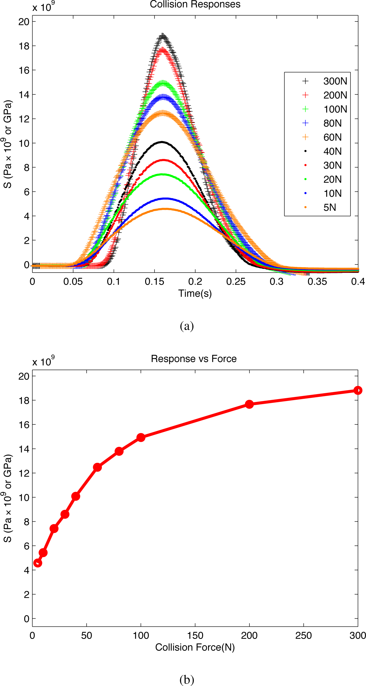
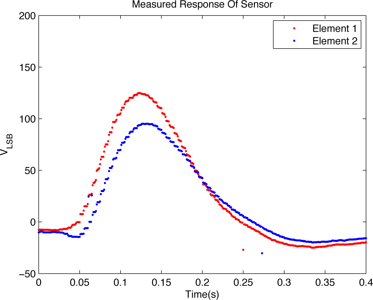
3.1.2. Results and Discussion

The sampled mean results, presented in Figure 4a, show the wide dynamic sensor range and consistent response to collision. For collision forces starting at 80 N and above, the measured impacts show some attenuation and clipping which is most likely a result of elasticity in the cover and compression distance of the polystyrene substrate. At high levels of force impact, the rigidity of the testing cover and compression distance becomes a limiting factor and noise source. The relation of applied collision stimuli to measured stress peaks is plotted in Figure 4b. The sensor response is not perfectly linear, but does resemble the engineering stress strain curves of foam under uniaxial compression [18], which reinforces the previous assertion that stress measured by the sensor is related to the localized compressive strain at the impact point.
The results in Figure 5 show that the measured response from collision for a non-planar application strongly correlate with the results from planar application. Some deviation is expected, but the sensor provides detection over the desired dynamic range for the non-planar application. The consistency between planar and non-planar experiments demonstrates the robust application properties of the sensor.
From Figure 6, there is evidence of time delay and difference in stress measured by the upper and lower elements. The authors believe the difference can be explained by delamination of the sensor elements over extended time; the initial testing prototype was constructed with double-sided tape not rated for repeated force impacts. Improved construction (adhesion) should eliminate the difference in sensors. The plots do show that the measured response of both elements is uniform. The digital response shown in Figure 6 is measured in ADC bits and shown in VLSB, which was previously discussed and calculated as 7.32 mV in Section 3.1.

3.2. Prototype II

The second prototype cover was designed to test the sensor functionality in commercial applications. The sensors were constructed from poled 28 µm thick PVDF film in the same form described in Figure 1a with Element 1 and Element 2 being opposite in polarity. The trilayer construction was implemented using multiple substrates including 1 mm, 3 mm and 5 mm polyurethane foam and similar thickness silicon rubber. The sensor elements were cut to shape to achieve total coverage of a protective fascia from a commercial robotic arm. The electronics board was reused from Prototype I. The size of the sensors for this test varied but were approximately 20 cm by 10 cm with some being slightly larger and others smaller. Due to the significant increase in surface area vs. the sensors in Prototype I, the expected sensation values in voltage should be smaller because of increased capacitive impedance of the element; additionally, the decreased depth of the substrate compression should lead to slightly less localized stress in the sensors. The following testing and results show that despite these changes the sensors provide more than adequate sensation for commercial viability. The data shown in Figures 710 is all displayed as the digital output of the ADC. The ADC bits correspond to VLSB steps previously discussed in Section 3.1; however, data is shown as bits instead of volts in order to provide the reader with a clear picture of the digital output of the sensor in a real-world environment.

3.2.1. Testing Method

The testing for commercial viability was accomplished with a multifaceted test routine. The prototype cover was attached to a commercial robotic arm and then put through a series of dynamics to gauge sensor response to stimuli. The following test states were used: normal operation (i.e., arm rotation with no collision) to characterize system noise and vibration detection, normal operation with simulated collisions to gauge signal to noise ratio of stimuli, normal operation with emergency stop (i.e., full speed arm rotation then emergency stop triggered) to gauge sensor false positive rejection, and dynamic movement with collisions and emergency stop to provide a full representation of sensor function. The sensor data captured and shown in the following sections corresponds to the 5 mm thick polyurethane foam substrate.

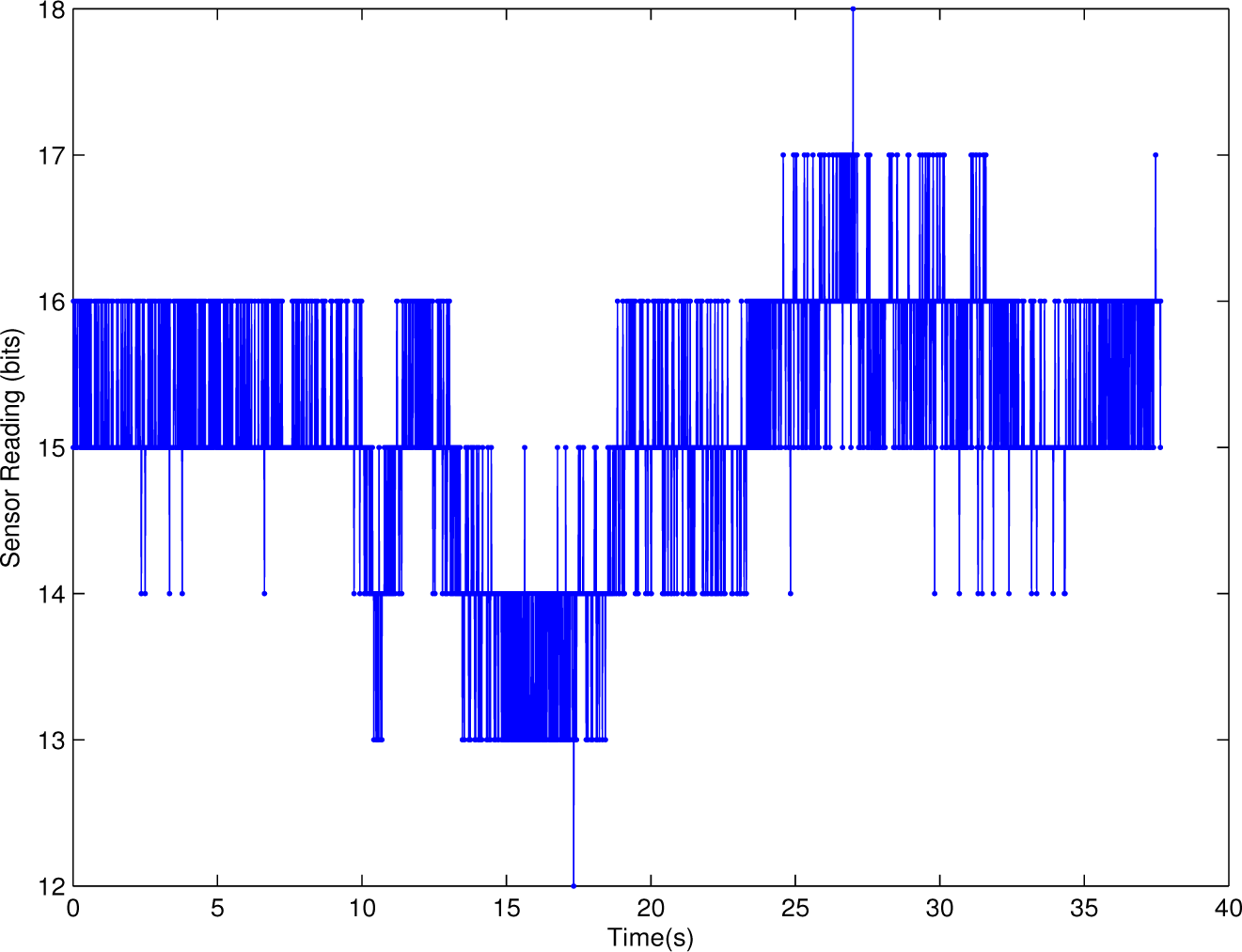
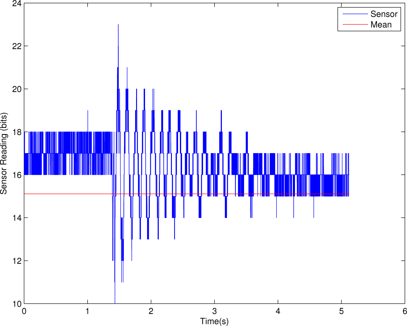
3.2.2. Normal Operation

Results for the prototype sensation during normal operational movements are shown in Figure 7. The protective cover is on the outside of an implement which is rotated at a constant speed of 10°/s through a full rotation during the captured time window. The resulting data in Figure 7 shows the sensors perception of the noise due to arm vibration and electronics. The measurements have a bias with mean of 15.109 ADC counts and a standard deviation of ±0.826 count. The low deviation of the measurements, less than one least significant bit of the ADC, shows that during movement of the arm the sensor measurement maintains the steady state values; furthermore, the dynamics and vibrations of the manipulated implement do not affect the sensor.

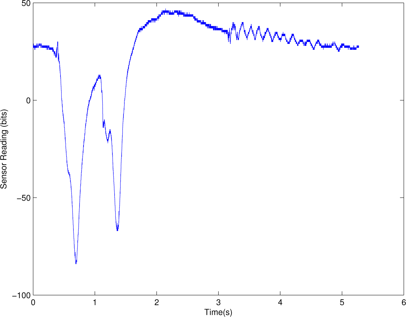
3.2.3. Collision Perception

The results for a collision scenario are shown in Figure 8. The sensor measurement shows several distinct collisions generated by the stimuli. The testing scenario involved rotating the arm at normal operation speeds as in the previous test, see Figure 7, and applying a collision stimulus with the human hand, tapping or pressing the sensor. The estimated force generated by these light taps would be 5–10 N, or significantly below the threshold of pain or harm. The collisions are clearly detectable over the previously shown sensor noise in Figure 7. For reference, standard mechanical or fiber optic switch based sensors currently deployed with the arms have a sensation threshold of 60 N to 100 N. This is the derived force detection level necessary for arms to prevent hazards such as crushing, shearing, cutting or severing and entanglement [19]. Lower sensation levels are necessary in order to eliminate unintended movements, system overrun during collision and other potential hazards [20]. The data in Figure 8 shows the multiple collision event for which there is a positive sensation at initiation of collision, and a negative sensor response on release due to the sensors holding the electric charge generated by the piezoelectric effect. The area under the curve, or total charge, is approximately equal for the collision and release phase. In addition, near there end there is a stop event on the arm. The light collisions are clearly perceptible above the system noise shown previously and easily detected with implementable algorithms; however, the third collision event which is a press, release, press, and release sequence is initiated during the decay period of the second event causing the initial positive peak to be obscured. The final sensor oscillation of the sensor data starting at the 10 s mark is an emergency stop, which will be discussed further in the next section. For Figure 8, there are two tapping collisions at 2 s and 4 s and then a press and release collision sequence at the 6 s mark.

3.2.4. Emergency Stop Detection

Results for sensor perception of an emergency stop event are shown in Figure 9. The sensor is at the previously shown steady state from Figure 7; however, the vibrations created from the emergency stop show in the measurements of Figure 9. The mean line, shown in red in Figure 9, shows that the emergency stop sensation oscillates around the mean and does not generate a large sensor response. The sensation level, a couple of ADC counts above mean, is well below the perceived collisions in Figure 8. The sensed stress during emergency stop can be attributed to a couple of the following factors: weight of leads causing stress due to vibration and movement of cabling, cover flex during emergency stop event, high dynamics causing sensor to minutely move due to weight of the element.

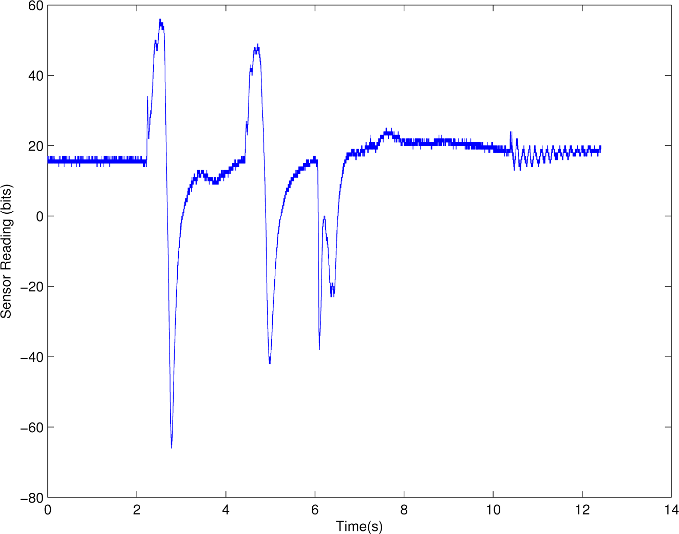
3.2.5. Dynamic Movement with Collisions and Emergency Stop

Finally, the results from a test run in which multiple collision events occur followed by an emergency stop are shown in Figure 10. The dynamic run included rotations similar to those in the previous results, Figures 79; however, the collision stimuli purely consist of low frequency pressing events and releases. Due to the capacitive nature and filter tuning, very low frequency collision is difficult to detect. For the data in Figure 10, there are two press-and-release events at about 0 s and then again at 1 s. The resulting spikes from initiation of collision are hard to sense, about 10 ADC above the mean, but present in the data. The resulting opposite polarity spike from release of the pressure is clearly shown. Following the second rebound there is a slow press and slow release that occurs starting at the 1.5 s mark, this can be seen and in this case the release is slower than the capacitive time constant of the system so the negative rebound is not seen. Finally we see the emergency stop reading, the estop and press-and-release collisions are of significantly different curve structure and sensor level. As a result, the data can be easily processed to detect the collision events while rejecting the emergency stop sensation. The collision events are clearly detectable over the mean. The reading generated from the emergency stop vibrations are significantly smaller than measured collision events, while both collision and emergency stop vibration events unique and differentiable from system noise.

4. Concluding Remarks

In contrast to existing technologies, the proposed sensor design shows strong collision sensation for both planar and non-planar surfaces. The pseudo-membrane construction eliminates not only mechanical issues associated with pressure and membrane based sensation but also increases applicability of the PVDF sensing technology. Furthermore, the uniform and consistent response of planar and non-planar applications eliminates hardware specialization needs such that modular collision detection systems can be created. The interface electronics and sensor construction is accomplished with commercially producible parts such that retrofitting is easily accomplished. The results support the theoretical relation of compressive stress to measured response in the local frame and the sensor measurements are a monotonically increasing function of the force.
The commercial prototype, Prototype II, and testing with commercial arms show the viability of the design. The decreased foam substrate thickness used for Prototype II does not significantly degrade the performance and sensation of the system. The results from commercial testing clearly show collision detection above the level of system noise and false positive generating vibrations. In contrast to mechanical based collision switches, the sensation range starting as low as a few Newtons allows the system to determine what sensation is caused by collision vs. false positive generated by vibration. The additional sensation range vs. other sensors, robust application form and lack of mechanical parts increase the viability of retrofitting deployed systems with sensors to increase operational efficiency with autonomy, increased movement speeds, and lower safety risk.
The novel sensor design and resulting testing in this paper shows strong promise for a robustly applicable collision detection solution for complex robotic arms and non-standard operating environments.

Acknowledgments

The authors gratefully thank Siemens AG for sponsoring the research.

Author Contributions

J. M. Wooten conceived and designed the sensor; J. M. Wooten also designed and performed the experiments; J. M. Wooten and D. M. Bevly analyzed the data; J. M. Wooten and J. Y. Hung wrote the paper.

Conflicts of Interest

The authors declare no conflict of interest.

References

  1. Fujimoto, I.; Yamada, Y.; Morizono, T.; Umetani, Y.; Maeno, T. Development of artificial finger skin to detect incipient slip for realization of static friction sensation, Proceedings of IEEE International Conference on Multisensor Fusion and Integration for Intelligent Systems (MFI-2003), Tokyo, Japan, 30 July–1 August 2003; pp. 15–20.
  2. Seminara, L.; Pinna, L.; Valle, M.; Basirico, L.; Loi, A.; Cosseddu, P.; Bonfiglio, A.; Ascia, A.; Biso, M.; Ansaldo, A.; et al. Piezoelectric polymer transducer arrays for flexible tactile sensors. IEEE Sens. J 2012, 12, 1–4. [Google Scholar]
  3. Shapiro, Y.; Wolf, A.; Kósa, G. Piezoelectric Deflection Sensor for a Bi-Bellows Actuator. IEEE/ASME Trans. Mechatron. 2013, 18, 1226–1230. [Google Scholar]
  4. Kolesar, E.S.; Dyson, C.S. Object imaging with a piezoelectric robotic tactile sensor. J. Microelectromech. Syst. 1995, 4, 87–96. [Google Scholar]
  5. Lee, S.; Ahn, Y.; Prabu, A.; Kim, K. Piezoelectric Polymer and Piezocapacitive Nanoweb Based Sensors for Monitoring Vital Signals and Energy Expenditure in Smart Textiles. J. Fiber Bioeng. Inform. 2013, 6, 369–381. [Google Scholar]
  6. Kymissis, J.; Kendall, C.; Paradiso, J.; Gershenfeld, N. Parasitic power harvesting in shoes, Proceedings of the Second International Symposium on Wearable Computers, Pittsburgh, PA, USA, 19–20 October 1998; pp. 132–139.
  7. Pi, Z.; Zhang, J.; Wen, C.; Zhang, Z.; Wu, D. Flexible piezoelectric nanogenerator made of poly(vinylidenefluoride-co-trifluoroethylene) (PVDF-TrFE) thin film. Nano Energy 2014, 7, 33–41. [Google Scholar]
  8. Han, H.; Nakagawa, Y.; Takai, Y.; Kikuchi, K.; Tsuchitani, S. PVDF film micro fabrication for the robotics skin sensor having flexibility and high sensitivity, Proceedings of the 2011 Fifth International Conference on Sensing Technology (ICST), Palmerston North, New Zealand, 28 November–1 December 2011; pp. 603–606.
  9. Kanik, M.; Aktas, O.; Sen, H.S.; Durgun, E.; Bayindir, M. Spontaneous High Piezoelectricity in Poly(vinylidene fluoride) Nanoribbons Produced by Iterative Thermal Size Reduction Technique. ACS Nano 2014, 8, 9311–9323. [Google Scholar] [Green Version]
  10. Canavese, G.; Stassi, S.; Cauda, V.; Verna, A.; Chiodoni, A.; Marasso, S.; Cocuzza, M. Different scale confinements of PVDF-TrFE as functional material of piezoelectric sensor devices, Proceedings of the 11th IEEE Conference on Sensors (IEEE Sensors 2012), Taipei, Taiwan, 28–31 October 2012; pp. 1–4.
  11. Mirbagheri, A.; Dargahi, J.; Aghili, F.; Parsa, K. Finite element analysis of a membrane-type piezoelectric tactile sensor with four sensing elements, Proceedings of the 4th IEEE Conference on Sensors (IEEE Sensors 2005), Irvine, CA, USA, 30 October–3 November 2005; pp. 353–356.
  12. Dahiya, R.; Metta, G.; Valle, M.; Sandini, G. Tactile Sensing - From Humans to Humanoids. IEEE Trans. Robot. 2010, 26, 1–20. [Google Scholar]
  13. Haddadin, S.; Albu-Schäffer, A.; de Luca, A.; Hirzinger, G. Collision detection and reaction: A contribution to safe physical Human-Robot Interaction, Proceedings of the IEEE/RSJ International Conference on Intelligent Robots and Systems (IROS-2008), Nice, France, 2008; pp. 3356–3363.
  14. Roh, Y.; Varadan, V.; Varadan, V.K. Characterization of all the elastic, dielectric, and piezoelectric constants of uniaxially oriented poled PVDF films. IEEE Trans. Ultrason. Ferroelectr. Freq. Control. 2002, 49, 836–847. [Google Scholar]
  15. Seminara, L.; Capurro, M.; Cirillo, P.; Cannata, G.; Valle, M. Electromechanical characterization of piezoelectric PVDF polymer films for tactile sensors in robotics applications. Sens. Actuators A: Phys. 2011, 169, 49–58. [Google Scholar]
  16. Damjanovic, D. Ferroelectric, dielectric and piezoelectric properties of ferroelectric thin films and ceramics. Rep. Prog. Phys. 1998, 61, 1267. [Google Scholar]
  17. Gere, J. Mechanics of Materials, 5th ed; Brooks/Cole Publishing: Belmont, CA, USA, 2001; p. 926. [Google Scholar]
  18. Bryson, J.A. Impact Response of Polyurethane. Ph.D. Thesis, Washington State University, 2009. [Google Scholar]
  19. International Standard Organization. Robots and Robotic Devices—Safety Requirements for Industrial Robots: Part 2: Robot Systems and Integration; Number ISO 10218-2:E; International Standard Organization: Geneva, Switzerland, 2011. [Google Scholar]
  20. International Standard Organization. Robots and Robotic Devices—Safety Requirements for Industrial Robots: Part 1: Robots; Number ISO 10218-1:E; International Standard Organization: Geneva, Switzerland, 2011. [Google Scholar]
Figure 1. Sensor design diagrams. (a) Pseudo-membrane sensor construction; (b) Rigid construction; (c) Pressure construction.
Electronics 04 00204f1
Figure 2. Charge amplifier schematic.
Electronics 04 00204f2
Figure 3. Sensor prototype used in testing showing planar (top of cover) and non-planar (rounded left end) sensor applications on example robotic arm shielding. Wires in picture connect sensor electrodes to instrumentation.
Electronics 04 00204f3
Figure 4. Results from sensor mounted on a planar surface. (a) Mean captured results for wide dynamic range of collision stimuli; (b) The relation of measured collision to force of object collision.
Electronics 04 00204f4
Figure 5. Results from sensor mounted on a non-planar surface. (a) Mean captured results for wide dynamic range of collision stimuli; (b) The relation of measured collision to force of object collision.
Electronics 04 00204f5
Figure 6. Mean digital response results of Element 1 and Element 2 for 5 N collisions.
Electronics 04 00204f6
Figure 7. Sensor measurements from test using robotic arm.
Electronics 04 00204f7
Figure 8. Sensor measurements from test using robotic arm with collision.
Electronics 04 00204f8
Figure 9. Sensor measurements from test using robotic arm with emergency stop.
Electronics 04 00204f9
Figure 10. Sensor measurements from test using robotic arm with collision and emergency stop.
Electronics 04 00204f10
Table 1. Material properties of PVDF film.
SymbolPropertyValueUnits
EYoung’s Modulus2–4nN/m2
d31Transverse Coefficient23pC/N
d33Compressive Coefficient−33pC/N
pPyroelectric Coefficient30µC/m2K

