Abstract
In this paper, a complete computer aided procedure based on the power density concept and aimed at the automatic design of EMI filters for power electronic converters is presented. It is rule-based, and it uses suitable databases built-up by considering information on passive components available from commercial datasheets. The power density constraint is taken into consideration by imposing the minimization of the filter volume and/or weight; nevertheless, the system in which the automatically designed filter is included satisfies the electromagnetic compatibility standards limits. Experimental validations of the proposed procedure are presented for two real case studies, for which the performance and the size of the best filter design are compared with those related to a conventionally designed one.
1. Introduction
The use of power electronic converters is very common in many industrial applications such as in the aeronautic and automotive fields, in hybrid vehicles, and in the electric aircraft context. This trend usually generates a reduction of the installation cost, but low volume and weight requirements are very important to facilitate installation, handling, and maintenance operations of the power converter. High power density power electronic converters are becoming increasingly essential for future markets [1,2].
The use of power devices with high speed commutation makes such systems unintentional EMI sources. Therefore, EMI attenuation solutions are necessary to ensure both the reliability and the electromagnetic compatibility of the system of which the power electronic converter is a part. In particular, EMI filtering is required to ensure the compliance with the emission limits imposed by the stringent technical standards [3,4,5,6,7,8,9,10,11,12], and behavioral models of electric motors can also be used to predict conducted interferences [13]. It is worth noting that electromagnetic compatibility and power density in power electronic converters are closely related issues.
The EMI filter is a part of the power electronic converter and it can significantly influence its size and weight. In order to address this issue, besides satisfying EMI limits, a further reduction of the filter size/weight is a requirement of crucial importance in the design phase [1,14,15].
The power density feature of EMI filters has been treated in scientific literature, but the presented techniques cannot be applied in a general way. In fact, some of these techniques propose only the use of high-performance magnetic materials to reduce the inductor core’s size [15]. In [16], some aspects for the design of high-density EMI filters for DC-fed motor drives are discussed and, in particular, grounding issues, circuit topologies, and some strategies to reduce the overall filter size are covered. In [17], the impedance interaction between the EMI filter and the noise propagation path, and its influence on the common mode (CM) filter design, are investigated; by applying this method, the impedance-mismatching concept is used to obtain a reduction of the CM inductor value that can potentially achieve a high power density. However, this method is only applied to a CM EMI filter design.
Other approaches propose the use of genetic algorithms to perform an EMI filter design [18]. In those cases, optimal solutions are usually obtained with a great number of iterations, thus resulting in a time consuming task.
In [19], the authors present software for designing EMI filters, limited only to one filter topology; the authors do not include the possibility of a discrete differential mode (DM) choke selection. Moreover, the paper only provides data about the CM core size, and the choice is not based on optimization.
In [20,21], a minimization of the filter volume is performed by using interpolated volumetric parameters. This approach can only be applied to the DM filter components and not to CM components because a parametrization of the volume curves is not possible for most of the commercially available CM chokes. Finally, a systematic approach for the volume optimization of a two-stage DM and CM EMI filter, essentially based on the ratio between the CM and DM inductance of the first filter stage, is proposed in [22].
After having defined both the EMI filter topology and the component values, the EMI filter can be setup according to a considerable number of feasible configurations. The conventional design of EMI filters, based on a trial and error approach, requires significant effort in terms of time, and it does not guarantee the optimal choice of filter components to obtain the maximum power density.
The first results of a rule-based computer-aided general procedure for the optimal design of EMI filters in terms of volume minimization have been proposed in [23] by the same authors.
In this paper, a comprehensive automatic procedure has been set-up; the procedure allows the design of the best filter configuration in a simple and fast way. Power density impact evaluation (i.e., volume, weight) of the filter configuration has been carried out, thus achieving useful results for engineers and scientists. The proposed algorithm can be implemented using any software programming environment and has a low computational demand.
Furthermore, suboptimal configurations can be compared with each other and with the best one so as to allow the designer to make the final choice and to also match further commercial constraints, if there are any.
The proposed procedure starts from the basic principle of conventional EMI filter design and considers the additional objective of pursuing the best power density for the EMI filter. A suitable test set-up enables one to obtain an experimental assessment of the automatic design procedure by comparing volume, weight, and performance.
2. The Rule-Based Computer-Aided EMI Filter Design Procedure
A multistage EMI filter configuration usually provides a stronger filter attenuation; consequently, it determines a higher cutoff frequency value than that obtained with a single stage filter. Furthermore, a higher value of the cutoff frequency leads to smaller values of the filter components and to physically smaller components. Therefore, even if the number of passive components is larger in a multistage configuration, overall, the latter may exhibit a smaller volume/weight than a single stage filter as has been demonstrated for the DM mode in [20]. However, it depends on the CM and DM required attenuations, on the electrical characteristics of the power electronic circuit under study, and on the adopted filter components. A verification of all feasible configurations is necessary to assess which of them allows one to obtain the best power density; the achievement of a trade-off is not a trivial task due to the broad variety of components that the market offers. Therefore, the choice of the best filter design, in terms of maximization of the power density, is not ensured by following a conventional design procedure.
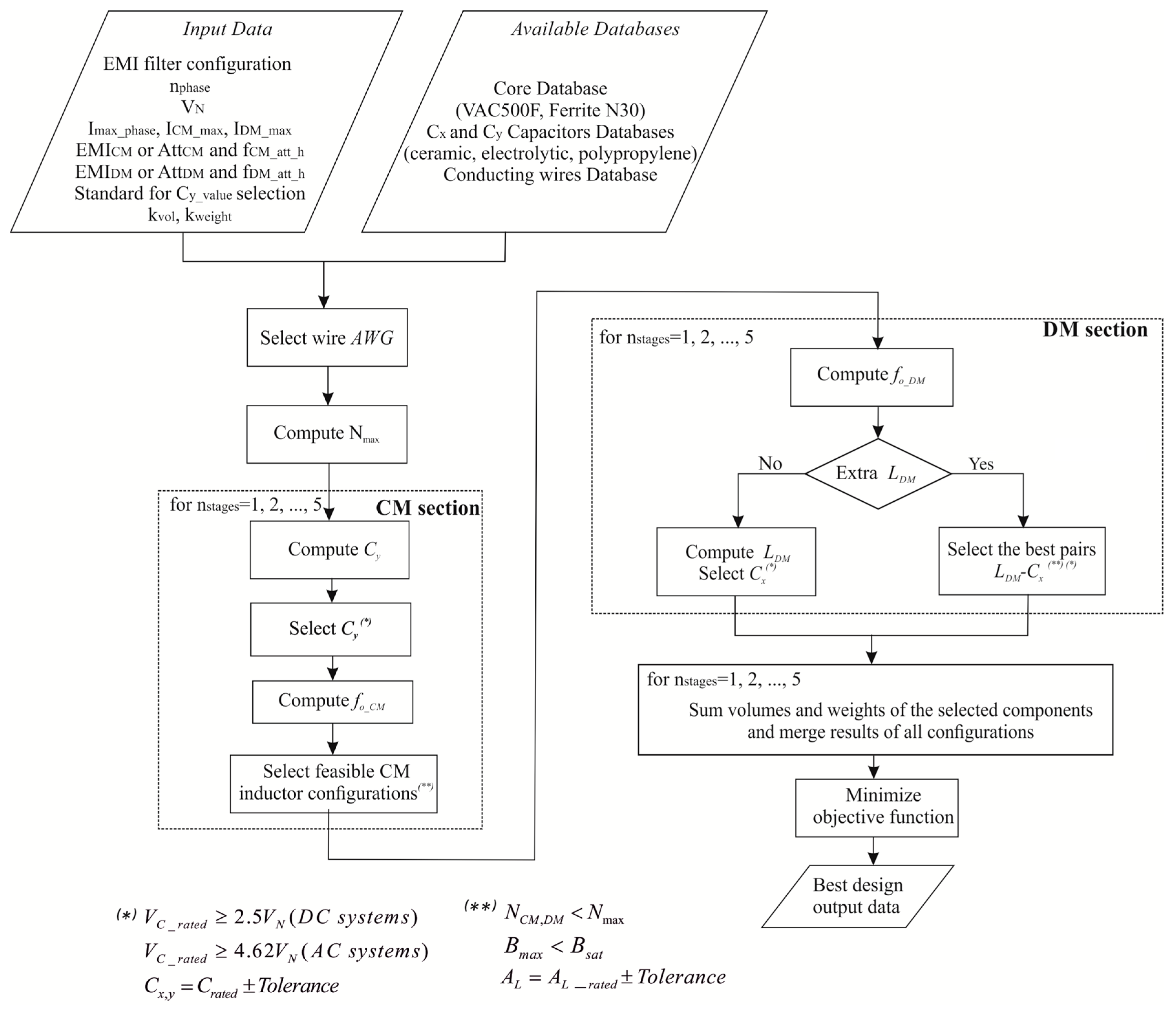
The proposed design procedure is a rule-based algorithm that takes into account the characteristics of the filter application: the power electronic circuits, the constraints of the filter design, and the databases of commercial components for the setup of the EMI filters. The flowchart of the design method is shown in Figure 1, in which AWG is the conducting wire diameter; nstages is the number of filter stages; Nmax is the maximum number of turns for each core; Cy and Cx define the capacitance of phase-to-ground and phase-to-phase capacitors, respectively; VC_rated and Crated indicate the capacitor rated voltage/capacitance, respectively; VN is the rated voltage of the power converter; and Bmax and Bsat are the maximum/saturation magnetic induction values, respectively.
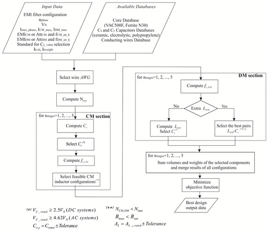
Figure 1.
Flowchart of the proposed design method.
Firstly, the designer must define the following Input Data:
- EMI filter topology (e.g., Γ, Π, T);
- nphase: number of AC phases or DC lines of the power electronic system;
- VN: rated voltage of the power converter;
- Imax_phase: maximum operating current;
- ICM_max, IDM_max: maximum value of the CM and DM currents;
- Standard for Cy_value selection: the CM capacitance value limits the ground current and thus it is related to safety issues. Either the SAE AES 1831 standard or the maximum ground leakage current are taken into consideration to define the capacitance value;
- kvol, kweight: coefficients provided by the designer which allow one to obtain the best design, assuming any linear combination of volume and weight as the objective function;
- filter design can be performed either on the basis of the measured CM/DM spectra (EMICM, EMIDM), or by explicitly giving the required CM/DM attenuations (AttCM, AttDM) and the CM/DM component frequencies to be attenuated (fCM_att_h and fDM_att_h). In the first case, the algorithm identifies the crucial point among the more relevant peaks at the lowest frequencies on the EMI spectra. Then, it computes the required attenuations for the CM and DM noise as expressed in (1) and (2), respectively:
where Ah_CM and Ah_DM are the amplitudes of the frequency spectrum components to be attenuated; Amax is the maximum amplitude allowed by the standard; and Δ is a safety margin (usually 6 dBµV).
For the reader’s convenience, it is worth recalling that EMI filters are generally low-pass passive filters realized with inductors and capacitors. The adopted arrangements can be Γ, Π, and T with longitudinal inductors and transversal capacitors. The choice of the passive filter topology is related both to the theoretical attenuation value of the chosen filter configuration (i.e., 40 dB/dec for Γ type L-C single stage, 60 dB/dec for Π or T type L-C single stage, etc.) and to the equivalent impedance magnitude of the equipment under test (EUT) and of the noise receiver. Therefore, a preliminary step for a proper EMI filter design is to suitably choose the filter topology by taking into account the criterion of maximum impedance mismatching between the source and the receiver.
Three databases of devices available on the market have been set up. The first one includes magnetic cores and it is populated with the following relevant data:
- core material and model;
- geometric dimensions and weight;
- inductance factor AL (µH/1 turn) at 10 kHz and the value of flux density saturation;
- AL tolerance.
The cores database currently contains components that allow an EMI filter design for applications up to some kW.
Furthermore, a second database of Y-type (CM noise reduction) and X-type (DM noise reduction) capacitors has been created. Ceramic Y-type capacitors, and aluminum electrolytic and polypropylene X-type capacitors for applications with high frequency ripple currents have been included. In particular, the aluminum electrolytic capacitors have a rated voltage of 160 V, 250 V, and 400 V, and a nominal capacitance range of 10 µF to 330 µF, whereas the polypropylene capacitors have a minimum rated voltage of 560 VDC/275 VAC (a lower rated voltage for this specific capacitor is not commercially available) and a nominal capacitance range of 0.01 µF to 10 µF.
The commercial capacitors database is populated with the following relevant data:
- brand, material, series, model, and package;
- rated capacitance and voltage;
- capacitance tolerance;
- geometric dimensions and weight.
Finally, a third database, including conducting wires, is provided. Hence, the volume/weight contribution given by the inductor wires (which may be relevant when dealing with rated power of hundreds of Watts and beyond) is included in the EMI filter calculations, and more effective results can be obtained.
After having defined the input data, the conventional design procedure steps are automatically repeated for different arrangements and finally the one which exhibits the best power density is selected.
It has to be underlined that a multi-stage filter may occupy a reduced volume in comparison with a single stage one, as stated in [20]; therefore, the rule-based algorithm analyses all feasible EMI filter designs considering a number of filter stages (nstages) up to five. The evaluation of a maximum number of five stages has been considered by the authors as a reasonable choice.
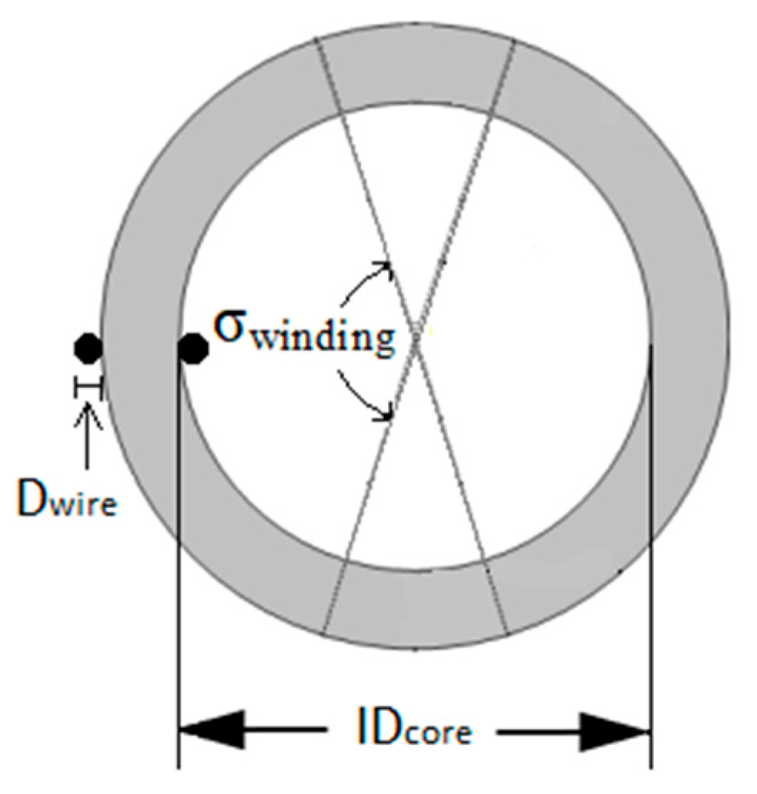
As shown in Figure 1, the first operation phase is the selection of wire size (AWG) on the basis of the maximum operating current entered by the designer. Then, the maximum number of achievable turns (Nmax) on each toroidal core of the database is computed as:
where is the inner circumference of the toroidal core, IDcore is the inner diameter of the toroidal core, Dwire is the wire diameter, and σwinding represents the maximum angle that the winding subtends on half of the core. It is acceptable to assume that σwinding is equal to 145° (Figure 2).
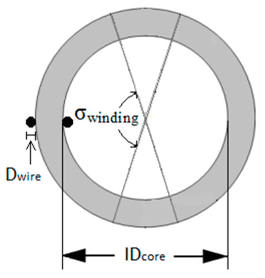
Figure 2.
Toroidal core: geometric parameters for Equation (3).
Then, the procedure performs the CM and DM filter design as described below.
2.1. CM Section Design
The procedure calculates, for nstages = 1, …, 5, the CM capacitance (CCM) and the CM inductance (LCM) as follows:
The cutoff or corner frequency (fo_CM/DM) is evaluated by considering that the attenuation of an L-C filter starts at this frequency and is rising with Att_intrCM/DM_filter, which is the inherent filter attenuation strictly related to its topology (e.g., 40 dB/dec for Γ type L-C single stage, 60 dB/dec for Π or T type L-C single stage, etc.). Thus, the required corner frequency can be evaluated according to:
thus obtaining:
As already underlined, the more relevant peaks of the EMI spectra are identified together with the corresponding frequencies. Then, for each of these frequencies, the required attenuations are evaluated for the CM and DM noise as expressed in (1) and (2), respectively. The corner frequency is then evaluated by (7) for each of the previous relevant frequencies and among them, the lowest frequency is selected as the cut-off frequency of the L-C filter; this frequency is usually lower than 150 kHz.
Then, the number of turns (NCM) needed to set up the required inductance is computed by (8):
where is the inductance value of the single CM choke winding. Equation (8) (and also (9) in the following) is derived by considering that for a highly symmetric magnetic core such as the toroidal inductor, the Ampere-law enables one to express the inductance as follows: , where is the inverse of the core reluctance evaluated along the centerline of the core : , A is the cross section area of the core, and is the magnetic permeability. Then, the minimum volume Cy capacitor is chosen from the database according to the design constraint , where k is a multiplier factor (equal to 2.5 for DC systems and 4.2 for AC systems [24]). In accordance with the computed value for the CM inductance, the cores allowing the effective realization of the CM choke (i.e., ) are selected from the database, also verifying the absence of cores saturation.
2.2. DM Section Design
It is possible to choose two alternative procedures by taking into consideration either the leakage inductance of the CM choke (No extra LDM) or a DM inductor (Extra LDM). The selection between the “No extra LDM” and “Extra LDM” procedures is performed by the designer. Moreover, both the procedures can be performed sequentially and then the most appropriate in terms of volume/weight can be selected.
Both procedures include the evaluation of the corner frequency versus the number of stages. Then:
- the “No extra LDM” procedure computes, for nstages = 1, …, 5, the leakage inductance of the feasible CM chokes and the corresponding computed value for the DM capacitance.After the computation of the CDM capacitance, the algorithm selects the capacitor with the minimum volume, according to the design constraint
- in the “Extra LDM” procedure, for nstages = 1, …, 5, the DM inductance candidate values are obtained on the basis of the X-capacitors values (ranging between 10 nF and 330 µF). For each DM core, the number of turns is then computed as follows:
where is the inductance value for each DM core. The cores permitting an effective realization are extracted from the database, in accordance with the constraint and ensuring no saturation. Finally, the feasible LDM-Cx pairs that permit one to setup the DM section according to the design constraints , are selected.
The “Extra LDM” may be more appropriate when the use of a higher LDM value is preferred to diminish the value or the size of DM capacitors.
The verification of the absence of the CM/DM cores saturation (Bmax < Bsat), performed in the design of both sections, allows one to obtain no degradation of the noise mitigation capability of the designed filter configurations.
The procedure also takes into account the component tolerances; in fact, neglecting the tolerances could degrade the filter performance. The capacitors database contains components with a tolerance range of ±20%; the cores database contains components with a tolerance of the AL value from −25% to +45% and from −30% to +30% for the vitroperm and ferrite materials, respectively. The negative tolerance percentage determines a degradation of the filter performance because it implies an actual value of the component lower than the nominal one and consequently a cutoff frequency higher than that required; hence, the filter will begin to attenuate at a higher frequency than the desired one. This issue is taken into account by choosing the commercial components based on the value related to the negative tolerance.
Finally, the EMI filter volume and weight of all realizable arrangements are computed and the one with the best power density is selected. A comparison among suboptimal results and the best arrangement is also allowed.
The filter configurations obtained by the automatic procedure are related to the specific components included in the databases, whose number and typology can be increased, if needed.
3. Experimental Setup
The automatic design procedure has been validated by experimental investigations by using a suitably devised test bench.
A PWM IGBT Voltage Source Inverter (VSI) supplying a three-phase load has been considered. The inverter is setup by a STGIPS10K60A power module and an Altera Cyclone III FPGA board realizing the PWM.
The inverter switching frequency is set to 20 kHz and the output voltage is 48 V.
A DC Line Impedance Stabilization Network (LISN) is used, with a voltage potentiality up to 600 V [25].
In order to assess the validity of the proposed approach, two case studies are considered with different three-phase loads:
- Case study #1: a 220 W induction motor, commonly used both in vehicles (road and marine vehicles, aircraft) and in DC systems, such as those installed in some residential/commercial smart buildings [26,27];
- Case study #2: a symmetric resistive load with low-power (7.2 W).
The experimental configuration scheme is given in Figure 3.
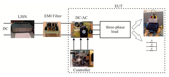
Figure 3.
Block diagram of the experimental rig.
4. Experimental Validation and Discussion
Experimental measurements and plate values are the inputs required for the proposed computer-aided design methodology.
The EMI measurements have been carried out by using an RF current probe R&S EZ-17 (20 Hz–100 MHz, maximum DC current equal to 300 A) and an R&S FSH4 (100 kHz–3.6 GHz) spectrum analyzer. A Tektronix TDS7254B 2.5 GHz–20 GS/s–4 channels oscilloscope has been employed for the time domain measurements.
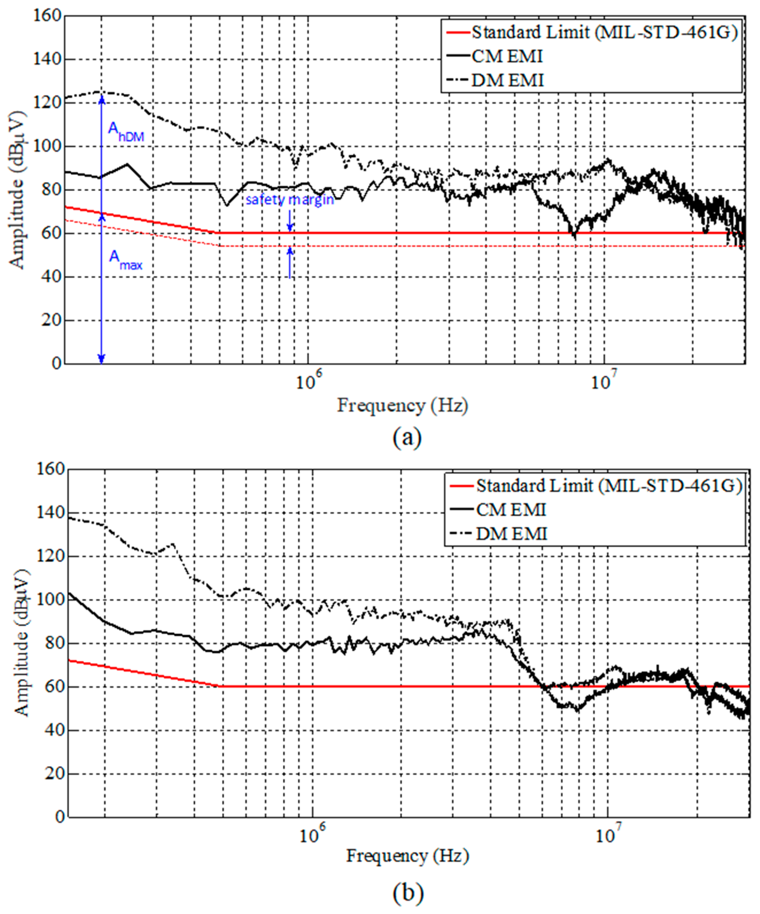
Figure 4 shows the CM and DM EMI spectra obtained for the two case studies. Both measured spectra show similar low frequency outlines, mainly due to the harmonics of the switching frequency. On the other hand, the induction motor drive has a significant impact on the high frequency EMI profile. Therefore, as expected, the load affects the noise emission profile. In fact, the test bench of case study #1 and #2 is the same, and it differs only for the three-phase load.
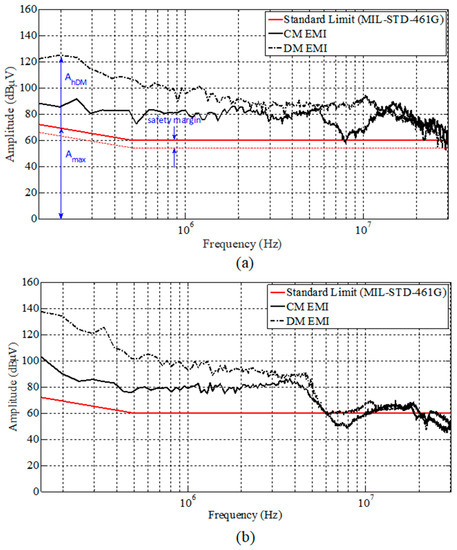
Figure 4.
Measured CM and DM EMI for (a) three phase induction motor load (b) three phase resistive load. In (a) the parameters reported in Equations (1) and (2) are also shown.
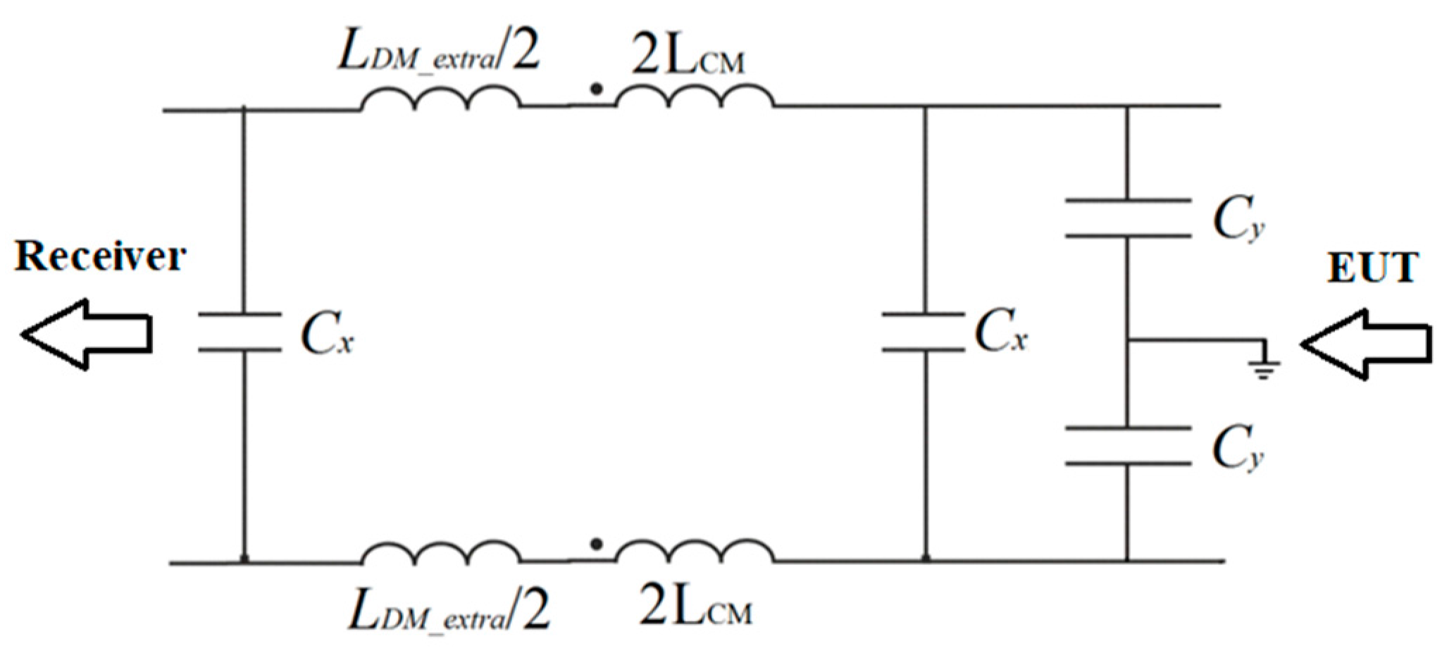
In both case studies, the limit curve of the Military Standard 461G [28] has been used as the EMI limit standard, a Γ-Π topology for the EMI filter has been considered (Figure 5), the SAE AS 1831 standard has been used for Cy selection, and volume optimization has been selected due to space constraints (kvol = 100% and kweight = 0%).
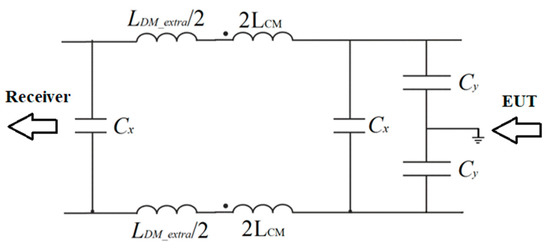
Figure 5.
Γ-Π filter topology (single stage) for the experimental setup.
In the first case study, the measured CM/DM spectra are used as input data; the following filter parameters have been returned by automatic processing:
- -
- AttCM = 30 dBμV@150 kHz;
- -
- -AttDM = 60 dBμV@170 kHz.
In Table 1, the input data used to run the rule-based algorithm are reported.

Table 1.
Input data for the rule-based algorithm–case study #1.
In the second case study, the following filter parameters have been obtained by the automatic processing of the measured CM/DM spectra:
- -
- AttCM = 25 dBμV@150 kHz;
- -
- AttDM = 60 dBμV@150 kHz.
In Table 2, the input data used to run the rule-based algorithm are reported.
Table 2.
Input data for the rule-based algorithm–case study #2.
For case study #1, the best design leads to a double stage (nstages = 2) filter without extra DM inductors among a total amount of 910 practicable arrangements.
For case study #2, the filter chosen for the experimental validation is one of the 1038 feasible configurations proposed by the design procedure, corresponding to the 28th one. Even if it is not the best configuration in terms of minimum volume, it has been chosen because it is a double stage (nstages = 2) filter with an extra LDM: in this way, it is also possible to validate the design procedure in the case of separate DM inductors.
Both EMI filters have been set-up. The benchmark is a single stage EMI filter designed and built-up by the conventional procedure [15,29].
To be significant, the filter performance comparison requires the consideration of the same test rig; for this reason, the comparison is performed with the EMI filter designed in [15], highlighting the improvement. The benchmark filter has been designed by using a high permeability nanocrystalline magnetic material for the CM choke. This material has the highest permeability and lowest coercive field strength, ensuring minimal eddy current losses and an outstanding frequency vs. permeability behavior. Furthermore, it is worth noting that the conventional design procedure, in which the cutoff frequency is lower than the power converter switching frequency, determines the same filter in both case studies.
In Table 3 and Table 4, the size and performance of the automatically designed filters and the benchmark filter are compared.
Table 3.
Filter design output data–case study #1.
Table 4.
Filter design output data–case study #2.
More compact filters are obtained with the automatic procedure, as expected. A reduction of about 56% in weight and about 46% in volume is reached in case study #1; a reduction of about 67% in weight and about 62% in volume is obtained in case study #2.
The automatic processing of the rule-based algorithm allows one to analyze a quite large search space, in order to obtain the arrangement determining the minimum volume/weight: the filter volume ranges from 13.88 cm3 up to 6591 cm3 and from 5.46 cm3 up to 6135.84 cm3 in the worst configuration, respectively, for case study #1 and #2.
The proposed automatic design algorithm stores data related to all feasible configurations. Therefore, it also allows one to perform extra analyses which are not possible with a manual design procedure. In particular, it allows one to compare the best EMI filter design to the suboptimal results: thus, the final choice is left to the designer; moreover, it is possible to evaluate whether an extra safety margin can be obtained whilst maintaining the same optimal value of the objective function.
Figure 6 shows the distribution of the 100 best designs around the first best configuration selected by the algorithm. It can be observed that, in the first case study, a relevant number of EMI filter designs are without extra DM inductors. Instead, in the second case study, the low value of the operating current reduces the likelihood of saturation of the magnetic core in the DM section design procedure; therefore, the configurations with extra DM inductors are more numerous, as shown in Figure 6b.
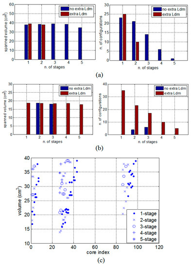
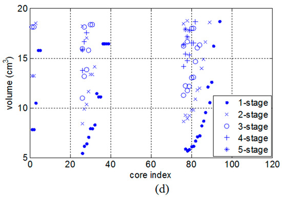
Figure 6.
Scatter plot and distribution of the best 100 configurations in case study #1 (a,c) and in case study #2 (b,d).
Moreover, the automatic design procedure has been repeated considering fixed input parameters and only increasing the CM attenuation value, starting from the minimum required value. The following range has been swept:
- -
- [30, 32, 34, 36, 38, 40, 42, 44, 46, 48, 50, 52, 54, 56] dBμV in case study #1;
- -
- [25, 30, 35, 40, 45, 50, 55, 60, 65] dBμV in case study #2;
The obtained results for both volume and number of stages are shown in Table 5 and Table 6. It can be noted that in both cases, the CM attenuation of the filter can be risen to an extra 10 dBμV safety margin without increasing the design volume. As a consequence, a better filter performance can be obtained, balancing the unavoidable non-idealities in the filter realization.
Table 5.
Volume and number of stages of the best design depending on the required CM attenuation–case study #1.
Table 6.
Volume and number of stages of the best design depending on the required CM attenuation–case study #2.
In the end, EMI measurements have been carried out in case studies #1 and #2 without any filter, with the conventionally designed filter, and with the automatically designed filter, to assess the filter mitigation performance.
The obtained filters show a good behavior since the filtered EMI meets the limit imposed by the standard under consideration, as shown in Figure 7. Despite the achievement of a higher compactness and power density, the proposed EMI filter design method enables compliance with the reference standard of the power electronic system under consideration, without a significant computational effort.
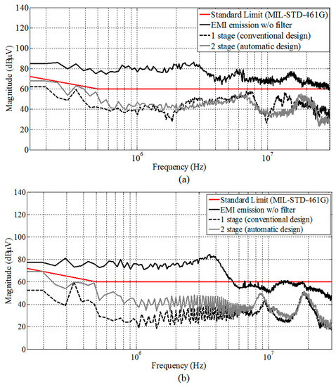
Figure 7.
Measured EMI with and without EMI filters (a) case study #1; (b) case study #2.
5. Conclusions
This work proposes an automatic design procedure oriented at obtaining high performing EMI filters with the minimum volume/weight.
The design procedure relies on a suitably devised rule-based algorithm and on databases of magnetic cores, capacitors, and conducting wires suitably selected among those offered by the market. It takes as inputs some relevant parameters that are evaluated from noise measurements and others defining the system arrangement. It outputs the best filter components in terms of performance, volume, and weight. Furthermore, the design procedure allows one to compare the most suitable EMI filter design to the suboptimal results, thus allowing the designer to have a final choice on the configurations to be selected. All the design steps, options, outputs, and design-related additional analyses are handled by the rule-based algorithm without a relevant computational effort. The proposed procedure has been experimentally validated in two case studies, both in terms of performance and increased power density. In addition to the compliance of the power electronic system under study with the reference standard, it has allowed us to achieve EMI filters with a considerable power density and higher compactness if compared with the conventional design.
In particular, an EMI filter size comparison has been carried out, obtaining a reduction of about 56% in weight and about 46% in volume in the first case study, and of about 67% in weight and about 62% in volume in the second case study.
Author Contributions
Guido Ala, Maria Carmela Di Piazza, Graziella Giglia, and Gianpaolo Vitale conceived the research activity; Graziella Giglia and Pericle Zanchetta gave advice on the filter design strategy; Guido Ala, Maria Carmela Di Piazza, and Gianpaolo Vitale conceived the proposed design procedure; Graziella Giglia and Massimiliano Luna performed the software implementation of the rule-based algorithm; Maria Carmela Di Piazza, Massimiliano Luna, Graziella Giglia, and Gianpaolo Vitale devised the test bench; Guido Ala, Giuseppe Costantino Giaconia, and Graziella Giglia contributed to the layout and the measurement set-up; Graziella Giglia performed the filter design and experimental tests; Guido Ala, Maria Carmela Di Piazza, Graziella Giglia, Massimiliano Luna, and Gianpaolo Vitale analyzed the experimental results; Guido Ala, Maria Carmela Di Piazza, and Graziella Giglia wrote the manuscript. All the authors revised and approved the final manuscript.
Conflicts of Interest
The authors declare no conflict of interest.
References
- Kolar, J.W.; Drofenik, U.; Biela, J.; Heldwein, M.L.; Ertl, H.; Friedli, T.; Round, S.D. PWM Converter Power Density Barriers. In Proceedings of the Power Conversion Conference (PCC ’07), Nagoya, Japan, 2–5 April 2007; pp. 9–29. [Google Scholar]
- Ahmed, H.F.; Cha, H.; Kim, S.-H.; Kim, D.-H.; Kim, H.-G. Wide Load Range Efficiency Improvement of a High-Power-Density Bidirectional DC–DC Converter Using an MR Fluid-Gap Inductor. IEEE Trans. Ind. Appl. 2015, 51, 3216–3226. [Google Scholar] [CrossRef]
- Grobler, I.; Gitau, M.N. Modelling and measurement of high-frequency conducted electromagnetic interference in DC–DC converters. IET Sci. Meas. Technol. 2017, 11, 495–503. [Google Scholar] [CrossRef]
- Grobler, I.; Gitau, M.N. Analysis, modelling and measurement of the effects of aluminum and polymer heatsinks on conducted electromagnetic compatibility in DC–DC converters. IET Sci. Meas. Technol. 2017, 11, 414–422. [Google Scholar] [CrossRef]
- Hu, B.; Tarateeraseth, V.; See, K.Y.; Zhao, Y. Assessment of electromagnetic interference suppression performance of ferrite core loaded power cord. IET Sci. Meas. Technol. 2010, 4, 229–236. [Google Scholar] [CrossRef]
- Sun, J.; Chen, W.; Yang, X. EMI Prediction and Filter Design for MHz GaN Based LLC Half-Bridge Converter. In Proceedings of the IEEE 8th International Power Electronics and Motion Control Conference (IPEMC 2016-ECCE Asia), Hefei, China, 22–26 May 2016; pp. 297–304. [Google Scholar]
- Kotny, J.L.; Duquesne, T.; Idir, N. Filter design method for GaN-Buck converter taking into account of the common-mode propagation paths. In Proceedings of the IEEE 20th Workshop on Signal and Power Integrity (SPI 2016), Turin, Italy, 8–11 May 2016; pp. 1–4. [Google Scholar]
- Liu, Y.; Peng, J.; Wang, G.; Wang, H.; See, K.Y. THD and EMI performance study of foil-wound inductor of LCL filter for high power density converter. In Proceedings of the IEEE 8th International Power Electronics and Motion Control Conference (IPEMC 2016-ECCE Asia), Hefei, China, 22–26 May 2016; pp. 3467–3471. [Google Scholar]
- Mallik, A.; Ding, W.; Khaligh, A. A Comprehensive Design Approach to an EMI Filter for a 6-kW Three-Phase Boost Power Factor Correction Rectifier in Avionics Vehicular Systems. IEEE Trans. Veh. Technol. 2017, 66, 2942–2951. [Google Scholar] [CrossRef]
- Silva, M.; Hensgens, N.; Oliver, J.; Alou, P. New considerations in the input filter design of a three-phase buck-type PWM rectifier for aircraft applications. In Proceedings of the IEEE Energy Conversion Congress and Exposition (ECCE 2011), Phoenix, AZ, USA, 17–22 September 2011; pp. 4087–4092. [Google Scholar]
- Danilovic, M.; Luo, F.; Xue, L.; Wang, R.; Mattavelli, P.; Boroyevich, D. Size and weight dependence of the single stage input EMI filter on switching frequency for low voltage bus aircraft applications. In Proceedings of the 15th International Power Electronics and Motion Control Conference (PEMC 2012), Novi Sad, Serbia, 4–6 September 2012; pp. LS4a.41–LS4a.47. [Google Scholar]
- Di Piazza, M.C.; Ragusa, A.; Vitale, G. An optimized feedback common mode active filter for vehicular induction motor drives. IEEE Trans. Power Electron. 2011, 26, 3153–3162. [Google Scholar] [CrossRef]
- Kahoul, R.; Azzouz, Y.; Ravelo, B.; Mazari, B. New Behavioral Modeling of EMI for DC Motors Applied to EMC Characterization. IEEE Trans. Ind. Electron. 2013, 60, 5482–5496. [Google Scholar] [CrossRef]
- Ala, G.; Di Piazza, M.C.; Giaconia, G.C.; Giglia, G.; Vitale, G. Design and performance evaluation of a high power density EMI filter for PWM inverter-fed induction motor drives. In Proceedings of the IEEE 15th International Conference on Environment and Electrical Engineering (EEEIC 2015), Rome, Italy, 10–13 June 2015; pp. 1573–1579. [Google Scholar]
- Ala, G.; Di Piazza, M.C.; Giaconia, G.C.; Giglia, G.; Vitale, G. Design and performance evaluation of a high power density EMI filter for PWM inverter-fed induction motor drives. IEEE Trans. Ind. Appl. 2016, 52, 2397–2404. [Google Scholar] [CrossRef]
- Maillet, Y.; Lai, R.; Wang, S.; Wang, F.; Burgos, R.; Boroyevich, D. High-Density EMI Filter Design for DC-Fed Motor Drives. IEEE Trans. Power Electron. 2010, 25, 1163–1172. [Google Scholar] [CrossRef]
- Luo, F.; Dong, D.; Boroyevich, D.; Mattavelli, P.; Wang, S. Improving high-frequency performance of an input common mode EMI filter using an impedance-mismatching filter. IEEE Trans. Power Electron. 2014, 29, 5111–5115. [Google Scholar] [CrossRef]
- Wang, F.; Shen, W.; Boroyevich, D.; Ragon, S.; Stefanovic, V.; Arpilliere, M. Design Optimization of Industrial Motor Drive Power Stage Using Genetic Algorithms. In Proceedings of the IEEE Industry Applications Conference, Tampa, FL, USA, 8–12 October 2006; pp. 2581–2586. [Google Scholar]
- Narayanasamy, B.; Jalanbo, H.; Luo, F. Development of Software to Design Passive Filters for EMI Suppression in SiC DC Fed Motor Drives. In Proceedings of the IEEE 3rd Workshop on Wide Bandgap Power Devices and Applications (WiPDA 2015), Blacksburg, VA, USA, 2–4 November 2015; pp. 230–235. [Google Scholar]
- Raggl, K.; Nussbaumer, T.; Kolar, J.W. Guideline for a Simplified Differential-Mode EMI Filter Design. IEEE Trans. Ind. Electron. 2010, 57, 1031–1040. [Google Scholar] [CrossRef]
- Raggl, K.; Nussbaumer, T.; Kolar, J.W. Model Based Optimization of EMC Input Filters. In Proceedings of the IEEE 11th Workshop on Control and Modeling for Power Electronics (COMPEL 2008), Zurich, Switzerland, 17–20 August 2008; pp. 1–6. [Google Scholar]
- Boillat, D.O.; Krismer, F.; Kolar, J.W. EMI Filter Volume Minimization of a Three-Phase, Three-Level T-Type PWM Converter System. IEEE Trans. Power Electron. 2017, 32, 2473–2480. [Google Scholar] [CrossRef]
- Ala, G.; Di Piazza, M.C.; Giaconia, G.C.; Giglia, G.; Luna, M.; Vitale, G.; Zanchetta, P. Computer Aided Optimal Design of High Power Density EMI Filters. In Proceedings of the IEEE 16th International Conference on Environment and Electrical Engineering (EEEIC 2016), Florence, Italy, 7–10 June 2016; pp. 1–6. [Google Scholar]
- Ozenbaugh, R.L.; Pullen, T.M. EMI Filter Design, 3rd ed.; CRC Press: Boca Raton, FL, USA, 2011; ISBN 9781439844755. [Google Scholar]
- Di Piazza, M.C.; Ragusa, A.; Vitale, G. Common Mode EMI Propagation in High Voltage DC supplied Induction Motor Drives for Electric Vehicles Application. In Proceedings of the IEEE International Electric Machines and Drives Conference (IEMDC 2009), Miami, FL, USA, 3–6 May 2009; pp. 647–652. [Google Scholar]
- Anand, S.; Fernandez, B.G. Optimal voltage level for DC microgrids. In Proceedings of the 36th Annual Conference on IEEE Industrial Electronics Society (IECON 2010), Glendale, AZ, USA, 7–10 November 2010; pp. 3034–3039. [Google Scholar]
- Kakigano, H.; Nomura, N.; Ise, T. Loss evaluation of DC distribution for residential houses compared with AC system. In Proceedings of the International Power Electronics Conference (IPEC), Sapporo, Japan, 21–24 June 2010; pp. 480–486. [Google Scholar]
- Department of Defense. Military Standard 461G: Requirements for the Control of Electromagnetic Interference Characteristics of Subsystems and Equipment; AMSC: Devens, MA, USA, 2015. [Google Scholar]
- Kumar, M.; Agarwal, V. Power line filter design for conducted electromagnetic interference using time-domain measurements. IEEE Trans. Electromagn. Compat. 2006, 48, 178–186. [Google Scholar] [CrossRef]

© 2018 by the authors. Licensee MDPI, Basel, Switzerland. This article is an open access article distributed under the terms and conditions of the Creative Commons Attribution (CC BY) license (http://creativecommons.org/licenses/by/4.0/).