Article

Decoding Performance Analysis of GNSS Messages with Land Mobile Satellite Channel in Urban Environment

1
National Time Service Center, Chinese Academy of Sciences, Xi′an 710600, China
2
Key Laboratory of Precision Navigation and Timing Technology, National Time Service Center, Chinese Academy of Sciences, Xi′an 710600, China
3
University of Chinese Academy of Sciences, Beijing 100049, China
4
School of Astronomy and Space Science, University of Chinese Academy of Sciences, Beijing 100049, China
5
School of Electronic, Electrical and Communication Engineering, University of Chinese Academy of Sciences, Beijing 100049, China
6
School of Information Science and Technology, Northwest University, Xi’an 710127, China
*
Author to whom correspondence should be addressed.
Electronics 2018, 7(11), 273; https://doi.org/10.3390/electronics7110273
Submission received: 24 September 2018 / Revised: 17 October 2018 / Accepted: 18 October 2018 / Published: 24 October 2018
(This article belongs to the Section Microwave and Wireless Communications)

Abstract

:
Demand for Global Navigation Satellite System (GNSS) applications in the urban environment has experienced a remarkable growth in recent years. However, the received signals are subjected to various urban channel impairments, like shadowing and multipath fading. Therefore, the decoding performance is different from that in open-sky conditions. In this paper, a two-state Land Mobile Satellite (LMS) channel based on the Markov process is used to model the urban channel properties, and then, the analysis of decoding performance in terms of frame error rate (FER) in the LMS channel is performed by evaluating the effect of three major influencing factors, specifically, coding and interleaving in the GNSS message, terminal speed, and satellite elevation angle. Extensive simulations are conducted on BDS-3 B1C B-CNAV1 message and GALILEO E5a F/NAV message. The results validate the excellent error correcting performance of the nonbinary low density parity check (NB-LDPC) code of the B-CNAV1 message and the effectiveness of interleaving in both of the messages in urban condition. Furthermore, it also shows that decoding performance improvement can be achieved with higher terminal speed and higher elevation angle in urban scenarios.

1. Introduction

The decoding performance of GNSS messages has a direct impact on the positioning, velocity, and timing solution. Initially, GNSS was designed to provide navigation data messages for user terminals in open-sky areas where the additive white Gaussian noise (AWGN) channel is usually used for modeling the transmission channel. Nowadays, the dramatically growing market for location-based services has triggered increased demand for GNSS in adverse environments such as urban areas [1,2,3]. However, shadowing and multipath effects caused by buildings and other obstacles that block the lines of sight (LOS) signals, along with the Doppler spread caused by terminal movement, makes the propagation characterization of urban channels differ markedly from AWGN channels [4]. The received power of the GNSS signals are approximately −130 dBm under the LOS condition, whereas 20–30 dB of signal attenuation can be observed with amplitude fluctuations and phase variations in the urban scenarios [5]. Therefore, it becomes necessary to assess the decoding performance of GNSS signals under the condition in which the terminals are operated. Besides, a realistic model should be selected to characterize the time-varying channel in the urban environment.
The LMS channel model describes the dynamic behavior of the channel between satellite and the mobile receiver with the existence of shadowing and multipath effects, and thus is being used for a wide range of applications in urban environment, such as mobile, broadcast and navigation [6,7,8]. It produces a time series of combined fading distributions in relation to the radio frequency, environment type, and satellite elevation angle through experimental measurements. Although the decoding performance in the LMS channel has been investigated in some previous studies [9,10,11], they mainly focused on the performance degradations in urban areas compared with open areas, and few investigated the related affecting factors in urban scenarios on decoding performance. In fact, the power attenuations and phase variations of the received signals are associated with terminal speed and elevation angle. In addition, the coding and interleaving techniques used in GNSS messages to correct transmission errors and to alter the fading statistics show different efficiency based on the channel condition.
The purpose of this paper is thus to evaluate the effects of coding and interleaving in GNSS messages and channel parameters such as terminal speed and elevation angle on the decoding performance in the LMS channel, so as to provide reference to future GNSS signal design for the urban environment. Considering the advanced features of the BDS-3 B1C signal [12] and Galileo E5a [13] signal to improve the robustness for users in difficult environments, we will focus on the performance of these two messages in this paper, namely, the B-CNAV1 message and F/NAV message. We will show that the above influencing factors have a significant effect on the message decoding performance. The results given in this work could also be used as a benchmark to test the decoding performance of GNSS receivers working in the urban environment.
The rest of the paper is organized as follows. In Section 2 the system model defining the urban scenarios is described. Section 3 analyzes the effects of coding and interleaving as well as terminal speed and elevation angle on the decoding performance. Simulation results under different conditions are given in Section 4. Section 5 concludes the paper and summarizes some general remarks based on the findings of this research.

2. System Model

Consider a coded and interleaved baseband GNSS message transmission system with perfect channel state information at the receiver. The simplified block diagram of the system is given below in Figure 1.

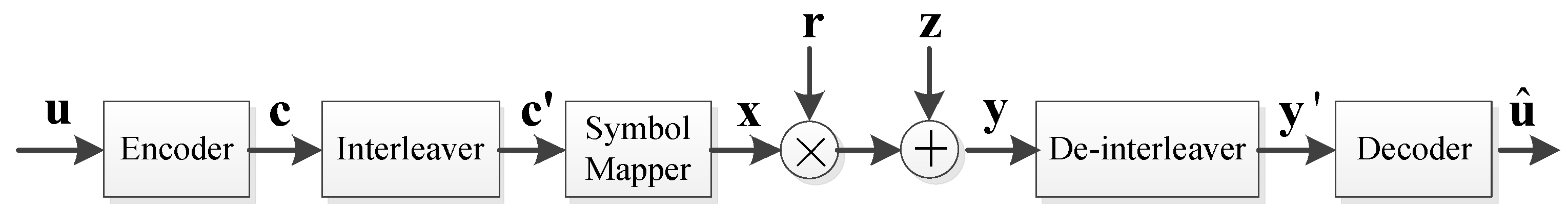
2.1. Transmitter and Receiver

The K bits navigation data information series u { 0 , 1 } K is encoded and the resulting codeword c { 0 , 1 } N of length N is then passed through the interleaver to produce the bit-interleaved codeword c { 0 , 1 } N . The symbol mapper maps c onto the BPSK symbols x { + 1 , 1 } N . The symbols are transmitted through a shadowing and multipath LMS channel with fading amplitudes r N . The faded signal is corrupted by an additive complex Gaussian noise z with zero-mean and a flat two-sided power spectral density of N 0 / 2 . At the receiver side, the de-interleaved symbols y are recovered by the decoder as u ^ , which is an estimate of information bits u .
The received baseband complex envelope signal in the LMS channel is given as
y = r x + z  
where the transmitted symbols x are multiplied by the fading gain r and the result is added with the Gaussian noise samples z .
Reception conditions can be divided into two cases in this work: (1) open-sky areas where r is constant and (2) urban areas where r follows a composite distribution in the LMS model.

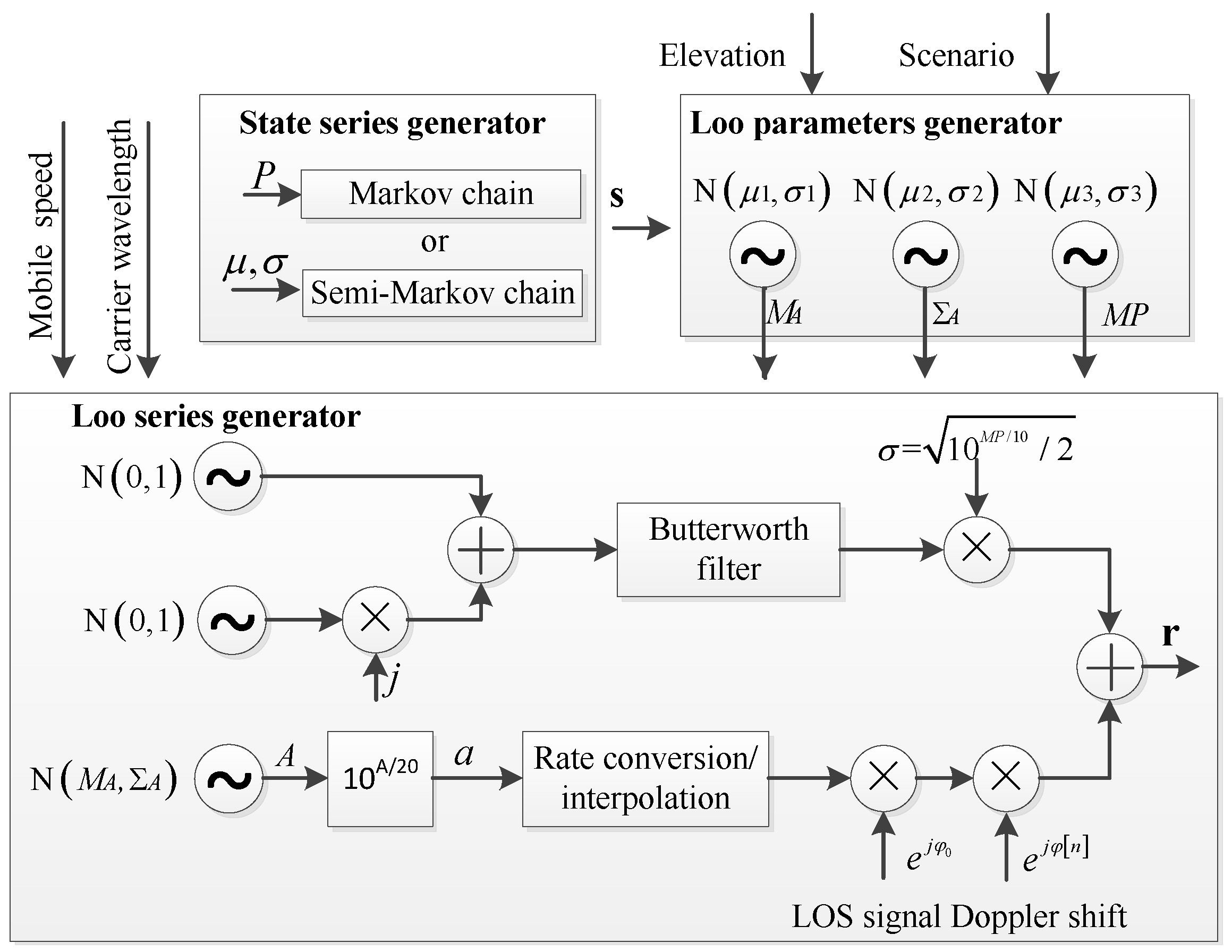
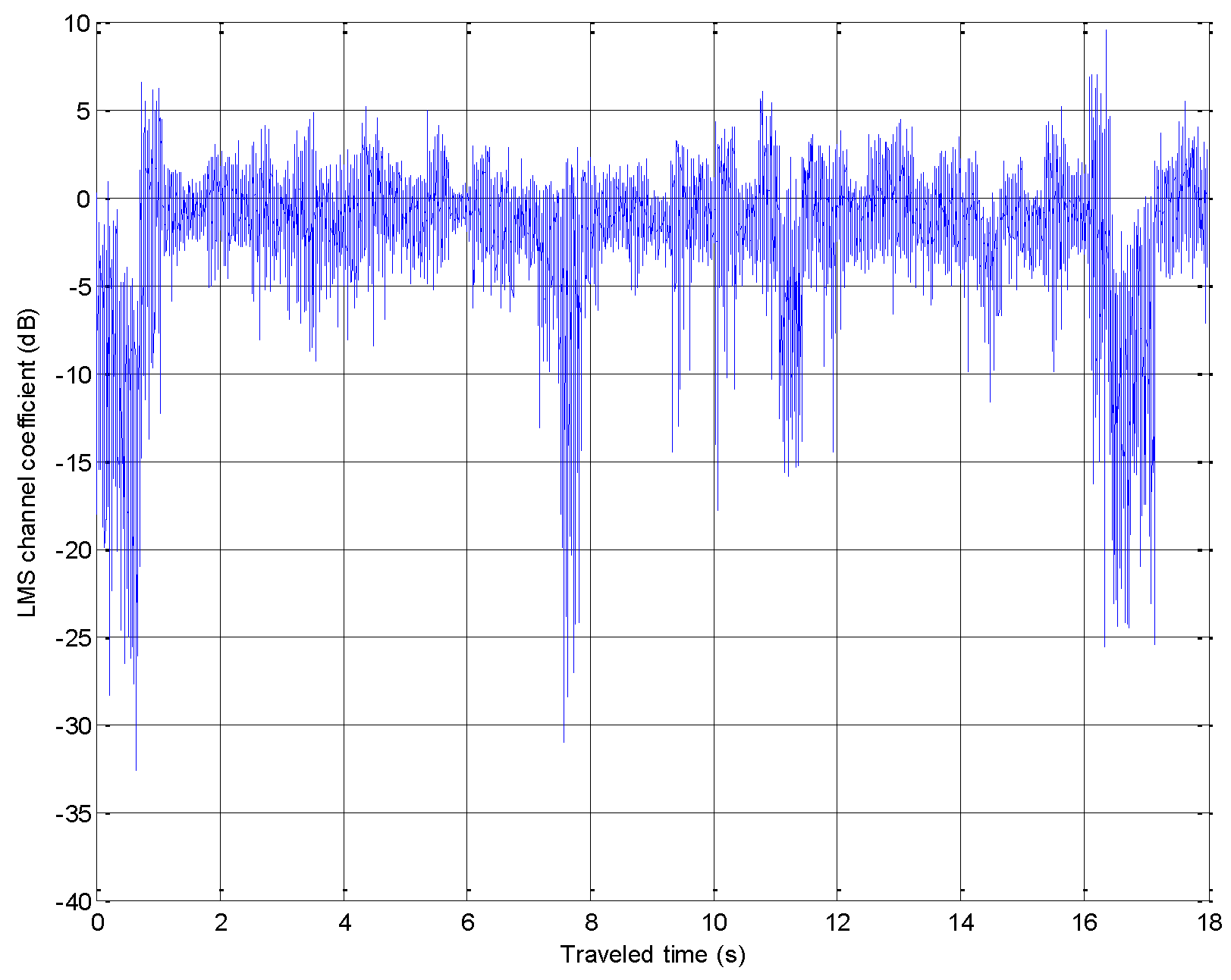
2.2. LMS Channel Model

In this paper, a two-state LMS channel model [14] is selected to evaluate the decoding performance because of the lower complexity and better fitting effect in comparison with the original three-state model [15]. It defines two states to describe the satellite transmission conditions: (1) a good state in which the LOS signal is either completely unblocked or moderately shadowed and (2) a bad state in which the LOS signal suffers moderate to heavy shadowing. Within each state, the signal envelopes follow the Loo distribution, which is an additive combination of a Log-normal distribution for partially shadowed LOS signal and a Rayleigh distribution for multipath signal with a constant average power.
The probability distribution function of Rayleigh distribution is given as
p ( r 0 ) = { r 0 σ 2 exp [ r 0 2 2 σ 2 ] r 0 0 0 otherwise  
where r 0 is the amplitude of the multipath component, and 2 σ 2 , or, in dB, M P = 10 log 2 σ 2 is the average multipath power of the multipath signal.
The probability distribution function of Log-normal distribution is expressed as
f ( a ) = 8.686 a Σ A 2 π exp [ ( 20 log a M A ) 2 2 Σ A 2 ]  
where a is the amplitude of the partially shadowed LOS component, M A and Σ A are the mean and standard deviation of the Log-normal distribution in dB, respectively.
The block diagram for the implementation of the two-stated LMS model is shown in Figure 2. The model is composed of a state series generator, a Loo parameters generator, and a Loo series generator. The state series generator controls the transition between the two states either by a first-order Markov chain according to a state transition probability matrix P , or by a semi-Markov chain in which duration of each state follows a Log-normal distribution with mean μ and standard deviation σ . A state transition is triggered once the mobile receiver travels a minimum state length. Based on the output of the state series generator, the Loo parameters generator computes the parameter set ( M A , Σ A , and M P ), all of which assume Gaussian distributions with means and standard deviations extracted from measurements under different environment scenarios and elevation angles.
{ f ( M A ) Ν ( μ 1 , σ 1 ) f ( Σ A | M A ) Ν ( μ 2 , σ 2 ) f ( M P ) Ν ( μ 3 , σ 3 )  
The overall complex series r involving multipath and LOS components with the input parameters set are produced by the Loo series generator. A Butterworth filter is included in the generation process of the multipath component to characterize the Doppler spread caused by the receiver movement. The sampling rates of multipath and LOS series are independent and associate with the mobile terminal speed and carrier wavelength. Therefore, a rate conversion process is applied so that the multipath and LOS series can be added with the same sampling period.

3. Decoding Performance Analysis in Urban Environment

Based on the previous analysis, the complex envelope of time series r depends on the fading characteristic of LMS channel due to multipath and shadowing reception, mobile terminal speed, and satellite elevation angle. In this section the effect of these factors on decoding for the LMS channel is surveyed.

3.1. Coding and Interleaving

Subjected to high free-space propagation losses with noises and interferences, modernized GNSS messages utilize forward error correction (FEC) coding to combat transmission errors. For example, the Galileo F/NAV message employs a convolutionary code for lower complexity and lower latency, and the BDS-3 B-CNAV1 message introduces a NB-LDPC code over Galois field GF(64) for superior error correcting performance.
For the binary coding like the convolutionary code of F/NAV message, the conditional probability distribution function of the received symbol y in (1) is
p ( y | x , r ) = 1 2 π σ z exp ( ( y x r ) 2 2 σ z 2 )  
where σ z 2 is the variance of the white Gaussian noise, r is the channel fading gain, and x is the coded symbol. Assuming that the perfect channel state information is available, i.e., the fading gain r is known at the receiver, the channel log-likelihood ratio is developed from (5) as
l j = log P ( x j = + 1 | y j , r j ) P ( x j = 1 | y j , r j ) = log P ( y j | x j = + 1 , r j ) P ( y j | x j = 1 , r j ) = 2 σ z 2 y j r j
The soft decision Viterbi decoders [16] choose the maximum likelihood (ML) sequence c ^ as follows
c ^ = arg max c C { j l j }  
where c is the candidate codeword and C denotes the entire codewords set.
For the NB-LDPC code over GF(q), let y = ( y 0 , y 1 , , y n 1 ) be the received symbol sequence in (1), the log-likelihood ratio vector L j = [ L j ( 0 ) , L j ( 1 ) , , L j ( q 1 ) ] T of the j-th received symbol y j is given by
L j ( x ) = log P ( y j | x ^ j , r j ) P ( y j | x , r j ) = 2 σ z 2 b = 1 p 1 | r j , b | | y j , b | Δ j , b
where x ^ j = { arg max x GF ( q ) P ( y j | x , r j ) } , p = log 2 ( q ) , y j , b is the b-th bit in binary sequence of y j , r j , b is the corresponding fading gain of y j , b , and Δ j , b = x b   XOR   x ^ j , b , where x b and x ^ j , b is the b-th bit in binary sequence of x and x ^ j , respectively.
The log-likelihood ratio derived from (8) is fed into the NB-LDPC decoder to initialize the received channel message for the iterative decoding such as Extended Min-Sum (EMS) algorithm [17].
The GNSS message decoding performance will degrade when the amplitude of the received signal fluctuates in time in the urban channel, because it is affected by multipath and shadowing fading as compared with stationary AWGN channel. Therefore, both the B-CNAV1 message and F/NAV message employ block interleavers with a coding scheme to spread the burst errors due to deep fade for improved performance in fading channel.
A block interleaver can be described as a two-dimensional array of N r rows and N c columns, where the encoded symbols are written in the row direction and read in the column direction. As for the B-CNAV1 message, the NB-LDPC coded symbols of subframe 2 and 3 are combined and interleaved by a block interleaver of 38 rows and 46 columns. For the F/NAV message, the convolutionary coded symbols of a page are interleaved by a block interleaver of 8 rows and 61 columns.

3.2. Terminal Speed

Decoding performance is directly related to the signal-to-noise ratio or carrier-power-to-noise density ratio (C/N0), while C/N0 is more generally used for the GNSS receiver. In the LMS channel, C/N0 at the receiver input is not constant and fluctuates with the channel states which determine the signal attenuation statistics. Specifically, the value of C/N0 will drop in the bad state when the receiver collects more shadowed signals. Therefore, C/N0 provides an indication of the reception condition in the LMS channel. In general, a long time spent in the bad state results in a much more deteriorated C/N0.
Typically, the state will be updated every time the mobile terminal travels a state frame, i.e., 5 m for L-band derived from the analysis of measurement database. The state transition is controlled by a first-order Markov chain and the occurrence of each state is defined by an absolute state probability matrix W ,
W = [ W 1 W 2 ]  
where W 1 and W 1 represent the total probability of being in the good state and bad state, respectively.
Consider a terminal travelling in an urban area with a constant speed V , the time duration of bad state can be calculated as
T 2 = L frame V N 2 = L frame V W 2 N t  
where T 2 is the time duration of bad state, L frame is the state frame in meters, W 2 is the probability of the terminal being in bad state, N 2 is the number of state frames corresponding to bad state, and N t is the total number of state frames. From (10), it can be seen that the time spent in the bad state deceases as terminal speed increases; consequently, the decoding performance will be improved.

3.3. Elevation Angle

GNSS terminals are supposed to be working at a wide range of elevation angles which vary with the movement of the satellite and terminal in the urban environment. However, the message decoding performance is different as the elevation angle changes, since the elevation angles affect the intensity of the non-LOS signals which consequently have a negative impact on the received C/N0. Non-LOS signals are more likely to be avoided at high elevation angles where signals are less likely to be blocked and reflected by local obstacles surrounding the terminal. Thus, a better decoding performance can be obtained at higher elevation angles. The LMS model can be applied for several typical elevation angles in urban areas by providing different Loo parameters to characterize the channel behavior.

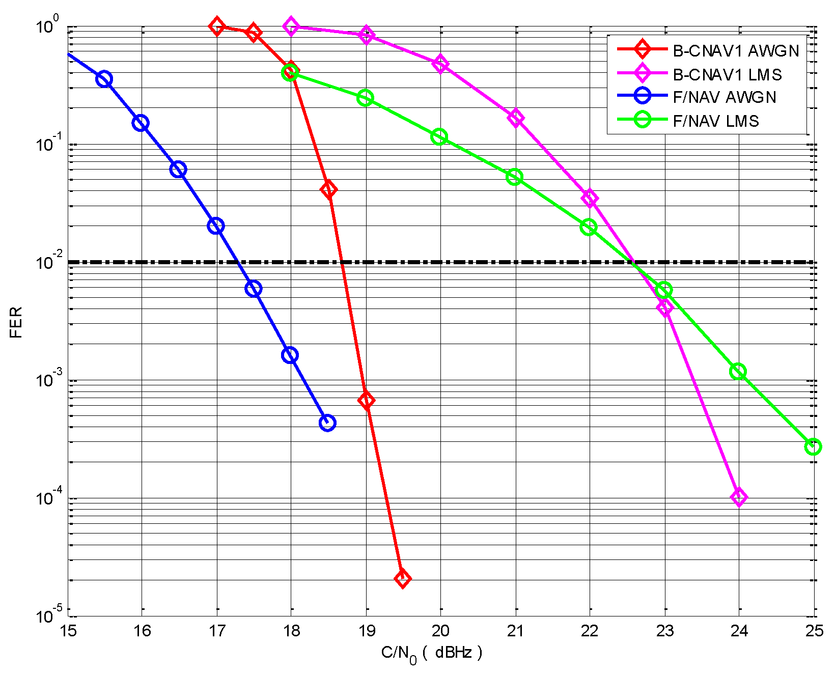
4. Simulation Results and Discussion

In this section, we first compare the message decoding performance of B-CNAV1 and F/NAV in the AWGN channel representing an open-sky environment and the LMS channel representing an urban environment, respectively. Next, we investigate the effects of coding and interleaving, terminal speed, and elevation angle on the decoding performance in urban scenarios. It is assumed that acquisition and tracking has been achieved, and the decoding performance is evaluated by FER with a threshold value of 10−2. The FER calculation for each C/N0 is performed once the error frame number reaches a predefined threshold. In this work, the predefined threshold is set to be 500, 200, and 50 for the low C/N0 region, median C/N0 region, and high C/N0 region, respectively. Note that the frame in this work indicates the basic structure unit of each message, in other words, it refers to subframe and page for B-CNAV1 and F/NAV, respectively. Particularly, Subframe 2, which contains satellite clock and ephemeris data in B-CNAV1 message, is considered in the following simulation as it is the most sensitive message information. A F/NAV message page containing 244-bit navigation data is first convolutionary encoded to 488 symbols, and after that, the encoded symbols are interleaved, and a 10-symbol preamble is added at the start of the page for synchronization. For B-CNAV1, the 1200-symbol Subframe 2 encoded from 600-bit data by a 64-ary (200, 100) LDPC code is combined and interleaved with the 528-symbol Subframe 3. The parameters concerning the decoding performance of the two messages are available in Table 1.
Assuming perfect channel state information at the receiver, an EMS algorithm with n m = 16 and an offset of 0.35 is applied to the B-CNAV message to decode the 64-ary (200, 100) LDPC code with a maximum of 50 iterations, and a Viterbi algorithm is employed to decode convolutionary code of F/NAV message.
The two-state LMS model is firstly simulated as shown in Figure 3, which illustrates the generated fading envelop in an urban environment at 60° elevation angle for a mobile terminal with a constant velocity of 50 km/h for 20 s. It can be seen that the received amplitude fluctuates with a maximum attenuation of nearly 30 dB.

4.1. Effects of Coding and Interleaving

In this subsection, we will show the effect of coding and interleaving with the same LMS channel parameters in Figure 3; the performance in the AWGN channel is also included for comparison. The FER performance of B-CNAV1 and F/NAV in the LMS channel and the AWGN channel are compared in Figure 4. There is an apparent performance degradation of 4 dB for B-CNAV1 and 5.3 dB for F/NAV in the LMS channel as compared with the AWGN channel at the FER threshold of 10−2. It should be note that the error correcting performance of the 64-ary (200,100) LDPC in B-CNAV1 is better than the (2,1,7) convolutionary code, however, the symbol rate of B-CNAV1 is twice that of F/NAV, which is equivalent to a 3 dB loss in C/N0, resulting in inferior message decoding performance in the AWGN channel when FER = 10−2, but the FER curve of B-CNAV1 drops more rapidly. Moreover, the B-CNAV1 exhibits an almost equal performance with F/NAV in the LMS channel at the FER threshold of 10−2, and even outperforms F/NAV as C/N0 increases, which indicates superior performance of the NB-LDPC code in the fading channel.
We now investigate the effect of interleaving by comparing the results of B-CNAV1 and F/NAV messages with and intentionally without interleaver. In the case of the AWGN channel, there seems to be little difference between the messages with and without interleaver as shown in Figure 5. This is because the range of fading variations in the AWGN channel is so small that few consecutive unreliable bits appear, hence the effect of the interleaver becomes negligible. On the other hand, in Figure 6, the performance of the F/NAV and B-CNAV1 with interleaver outperforms the ones without interleaver by approximately 7 dB and 0.9 dB in the LMS channel, respectively, because the interleavers break the deeply faded bits. Therefore indicating that interleaving is beneficial to decoding performance in the fading channel, but not valid for the AWGN channel.

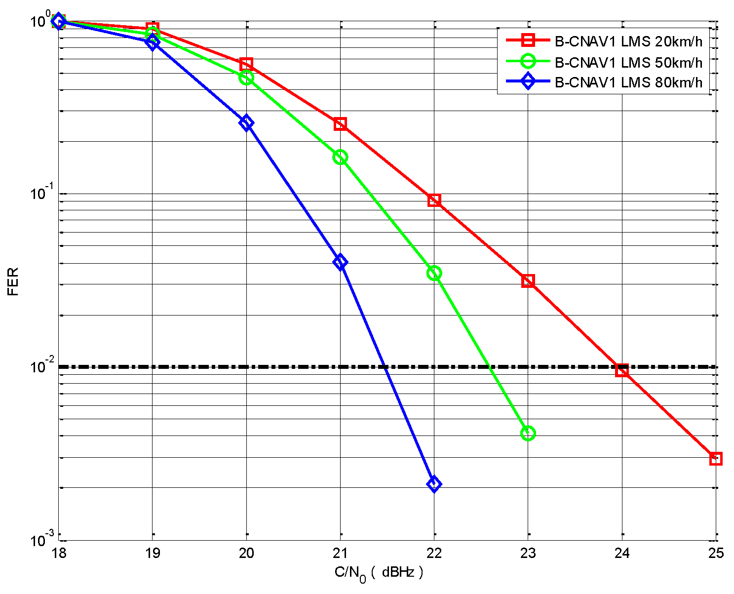
4.2. Effects of Terminal Speed

We now compare the FER as a function of the terminal speed in urban environment. Figure 7 shows the FER results of B-CNAV1 with terminal speeds of 20 km/h, 50 km/h, and 80 km/h; the elevation angle is 60°, therefore, only speed is considered here for contribution to decoding performance. It can be observed that FER decreases as the terminal speed increases for a fixed elevation angle, which agrees with the expected behavior as explained in Section 3.

4.3. Effects of Elevation Angle

The previous subsection has demonstrated the improvement of decoding performance with increasing terminal speed. In this subsection, we focus on the performance with different elevation angles, i.e., 40°, 60°, and 80°. The corresponding results are shown in Figure 8, and it can be observed that FER decreases with increasing elevation angle. The results comply with the previous analysis that the received signals are less likely to be interfered by non-LOS observations for satellites with a higher elevation angle, consequently, the decoding performance are better than lower elevation signals.

5. Conclusions

This paper has investigated the three major influencing factors, (i.e., coding and interleaving, terminal speed, and elevation angle) on the decoding performance of GNSS in the urban environment based on the LMS channel model. Simulation results show that the powerful GF(64)-LDPC code of B-CNAV1 message is necessary to compensate for the performance degradation caused by the higher data rate compared with the convolutionary code of the F/NAV message in both urban and open-sky scenarios. Besides, the urban channel leads to significant performance degradation of 4 dB and 5.3 dB for B-CNAV1 and F/NAV, respectively. The results also demonstrate the effectiveness of interleaving in the urban channel where burst errors are present. Another useful observation is that increasing terminal speed gives better decoding performance in an urban environment. Finally, the performance improvement of signals with higher elevation angles is obtained by the reduced envelope variations in the urban channel due to a more satisfactory LOS signal reception condition.

Author Contributions

J.K. conceived and wrote the paper; X.L. and X.W. supervised the paper and suggested modifications; X.C. and S.T. analyzed the data.

Funding

This work was supported by the Natural Science Basic Research Plan in Shaanxi Province of China (No. 2018JM1025) and the National Natural Science Foundation of China (No. 11403018).

Conflicts of Interest

The authors declare no conflict of interest.

References

  1. Escher, M.; Stanisak, M.; Bestmann, U. Future Automotive GNSS Positioning in Urban Scenarios. In Proceedings of the 2016 International Technical Meeting of The Institute of Navigation (ITM), Monterey, CA, USA, 25–28 January 2016; pp. 836–845. [Google Scholar]
  2. Zhu, N.; Marais, J.; Bétaille, D.; Berbineau, M. GNSS Position Integrity in Urban Environments: A Review of Literature. IEEE Trans. Intell. Transp. Syst. 2018, 19, 2762–2778. [Google Scholar] [CrossRef]
  3. Park, S.G.; Cho, D.J. Smart framework for GNSS-based Navigation in Urban Environments. Int. J. Satell. Commun. Netw. 2017, 35, 123–137. [Google Scholar] [CrossRef]
  4. Roudier, M.; Grelier, T.; Ries, L.; Garcia-Pena, A.; Julien, O.; Poulliat, C.; Boucheret, M.L.; Kubrak, D. Optimizing GNSS Navigation Data Message Decoding in Urban Environment. In Proceedings of the 2014 IEEE/ION Position, Location and Navigation Symposium (PLANS), Monterey, CA, USA, 5–8 May 2014; pp. 581–588. [Google Scholar]
  5. Zheng, L.; You, Z.; Zhang, G.; Zhang, G.; Zhao, S. Acquisition of Weak GNSS Signals Based on Non-coherent Integration. J. Tsinghua Univ. 2014, 54, 794–798. [Google Scholar]
  6. Andreotti, R.; Emmanuele, A.; Fontanella, D.; Zanier, F.; Luise, M. Code-Shift-Keying (CSK) with Advanced FEC Coding for GNSS Applications in Satellite Multipath Channel. In Proceedings of the 7th ESA Workshop on Satellite Navigation Technologies and European Workshop on GNSS Signals and Signal Processing (NAVITEC), Noordwijk, The Netherlands, 3–5 December 2014. [Google Scholar]
  7. Rieche, M.; Ihlow, A.; Arndt, D.; Pérez-Fontán, F.; Galdo, G.D. Modeling of the Land Mobile Satellite Channel considering the Terminal’s Driving Direction. Int. J. Antennas Propag. 2015, 2015, 372124. [Google Scholar] [CrossRef]
  8. Xi, L.; Yang, W.; Zhao, D.F. Improved Two-State LMS Channel Model for DVB-SH System. J. Univ. Electron. Sci. Technol. China 2016, 45, 179–184. [Google Scholar]
  9. Anghileri, M.; Paonni, M.; Fontanella, D.; Eissfeller, B. Assessing GNSS Data Message Performance: A New Approach; Inside GNSS: Eugene, Oregon, USA, 2013; pp. 60–70. [Google Scholar]
  10. Roudier, M.; Garcia-Pena, A.; Julien, O.; Grelier, T.; Ries, L.; Poulliat, C.; Boucheret, M.-L.; Kubrak, D. Demodulation Performance Assessment of New GNSS Signals in Urban Environments. In Proceedings of the 27th International Technical Meeting of The Satellite Division of the Institute of Navigation (ION GNSS+), Tampa, FL, USA, 8–12 September 2014; pp. 3411–3429. [Google Scholar]
  11. Salgueiro, F.; Luise, M.; Zanier, F.; Crosta, P. Pilot-aided GNSS Data Demodulation Performance in Realistic Channels and Urban Live Tests. In Proceedings of the 8th ESA Workshop on Satellite Navigation Technologies and European Workshop on GNSS Signals and Signal Processing (NAVITEC), Noordwijk, The Netherlands, 14–16 December 2016; pp. 1–8. [Google Scholar]
  12. BeiDou Navigation Satellite System Signal in Space Interface Control Document Open Service Signals B1C (Versison 1.0); China Satellite Navigation Office: Beijing, China, 2017.
  13. European GNSS (Galileo) Open Service Signal in Space Interface Control Document, Issue 1.2; European Union and European Space Agency: Paris, France, 2015.
  14. Prieto-Cerdeira, R.; Perez-Fontan, F.; Burzigotti, P.; Bolea-Alamañac, A.; Sanchez-Lago, I. Versatile Two-state Land Mobile Satellite Channel Model with First Application to DVB-SH Analysis. Int. J. Satell. Commun. Netw. 2010, 28, 291–315. [Google Scholar] [CrossRef]
  15. Fontan, F.P.; Vazquez-Castro, M.; Cabado, C.E.; Garcia, J.P.; Kubista, E. Statistical Modeling of the LMS Channel. IEEE Trans. Veh. Technol. 2001, 50, 1549–1567. [Google Scholar] [CrossRef]
  16. Hori, Y.; Ochiai, H. An Interleaver Optimization for BICM-OFDM with Convolutional Codes over Frequency-Selective Block Fading Channels. In Proceedings of the 2014 IEEE Wireless Communications and Networking Conference (WCNC), Istanbul, Turkey, 6–9 April 2014; pp. 769–774. [Google Scholar]
  17. Declercq, D.; Fossorier, M. Decoding Algorithms for Nonbinary LDPC Codes Over GF(q). IEEE Trans. Commun. 2007, 55, 633–643. [Google Scholar] [CrossRef]
Figure 1. Structure of the Global Navigation Satellite System (GNSS) message transmission system.
Electronics 07 00273 g001
Figure 2. Block diagram for implementation of the two-state Land Mobile Satellite (LMS) channel model.
Electronics 07 00273 g002
Figure 3. Simulated signal amplitude series in urban environment.
Electronics 07 00273 g003
Figure 4. Comparison of frame error rate (FER) for B-CNAV1 and F/NAV in additive white Gaussian noise (AWGN) and LMS channels.
Electronics 07 00273 g004
Figure 5. Comparison of FER for B-CNAV1 and F/NAV with and without interleaver in the AWGN channel.
Electronics 07 00273 g005
Figure 6. Comparison of FER for B-CNAV1 and F/NAV with and without interleaver in the LMS channel.
Electronics 07 00273 g006
Figure 7. FER of B-CNAV1 message at different terminal speed.
Electronics 07 00273 g007
Figure 8. FER of B-CNAV1 message at different elevation angle.
Electronics 07 00273 g008
Table 1. Message parameters of B-CNAV1 and F/NAV.
ParametersB-CNAV1F/NAV
Coding Scheme64-ary (200,100) LDPC code(2,1,7) Convolutional code
Frame Length (symbol)1200 (Subframe 2)500 (Page)
Code Rate1/21/2
Symbol Rate (symbol/s)10050
Interleaving SchemeBlock interleaver
(46 columns × 38 rows)
Block interleaver
(61 columns × 8 rows)

