A Novel Feature-Based Approach for Indoor Monocular SLAM


Abstract
:1. Introduction
- A coarse to fine feature tracking scheme that is highly reliable and robust against quick camera movement;
- Depth information propagation that helps the proposed system to estimate camera pose parameters as the camera moves;
- A delayed feature initialization approach that only estimates the depth of new features when the observed parallax exceeds a threshold.
2. Related Work
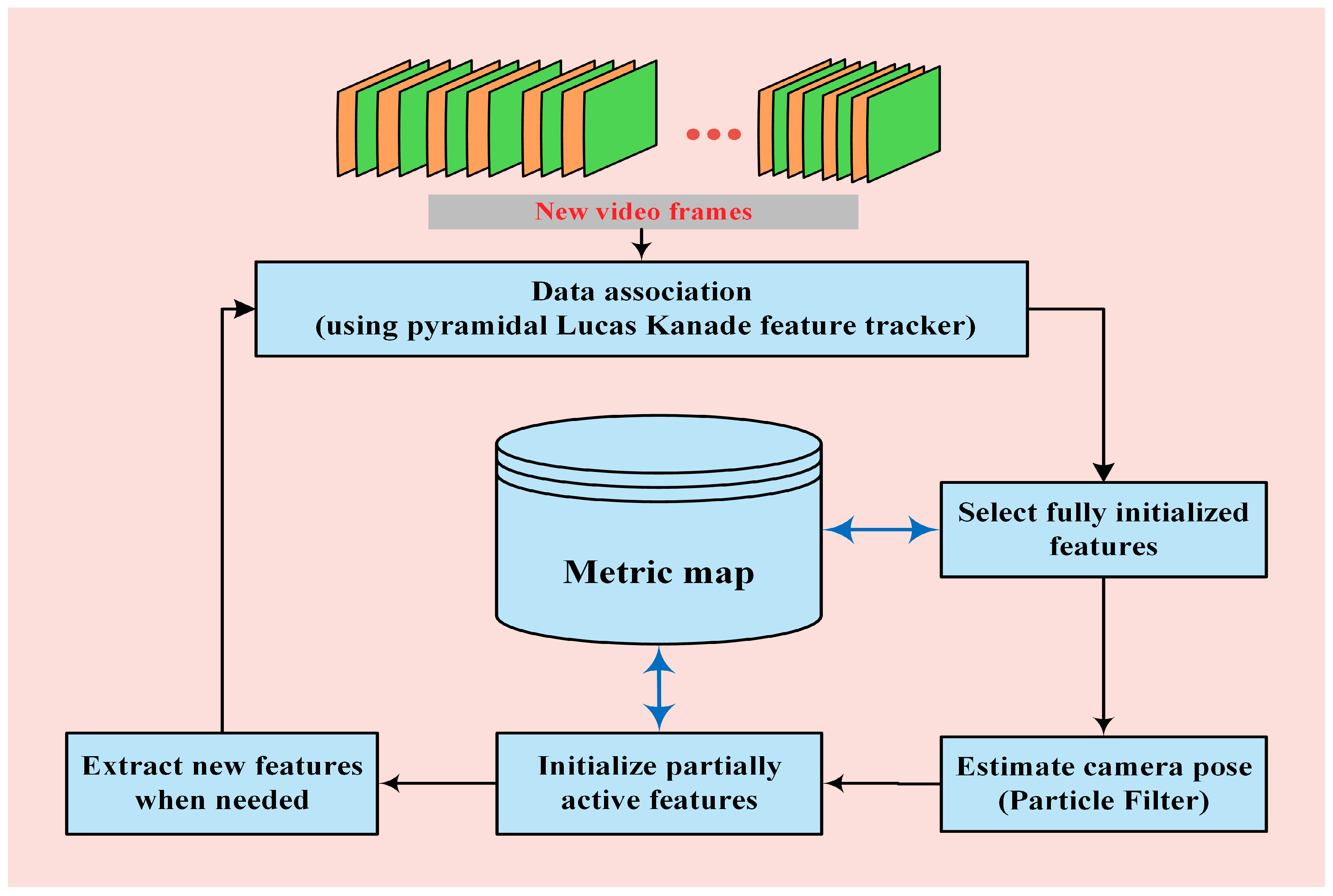
3. Proposed Method
3.1. PF Implementation
3.2. Feature Extraction and Tracking
3.3. Pose and Map Initialization
3.4. Initialization of New Features
3.5. Feature Management
4. Experimental Results
5. Conclusions
Author Contributions
Funding
Conflicts of Interest
References
- Ababsa, F.; Mallem, M. Robust camera pose estimation using 2d fiducials tracking for real-time augmented reality systems. In Proceedings of the ACM SIGGRAPH International Conference on Virtual Reality Continuum and Its Applications in Industry, Singapore, 16–18 June 2004; pp. 431–435. [Google Scholar]
- Xu, K.; Chia, K.W.; Cheok, A.D. Real-time camera tracking for marker-less and unprepared augmented reality environments. Image Vis. Comput. 2008, 26, 673–689. [Google Scholar] [CrossRef]
- Dong, Z.; Zhang, G.; Jia, J.; Bao, H. Efficient keyframe-based real-time camera tracking. Comput. Vis. Image Underst. 2014, 118, 97–110. [Google Scholar] [CrossRef]
- Clemente, L.A.; Davison, A.J.; Reid, I.D.; Neira, J.; Tardós, J.D. Mapping large loops with a single hand-held camera. In Proceedings of the Robotics: Science and Systems, Atlanta, GA, USA, 27–30 June 2007; pp. 352–360. [Google Scholar]
- Eade, E.; Drummond, T. Unified loop closing and recovery for real time monocular slam. In Proceedings of the British Machine Vision Conference, Leeds, UK, 1–4 September 2008; pp. 136–145. [Google Scholar]
- Hartley, R.; Zisserman, A. Multiple View Geometry in Computer Vision, 2nd ed.; Cambridge University Press: New York, NY, USA, 2003. [Google Scholar]
- Fitzgibbon, A.W.; Zisserman, A. Automatic camera recovery for closed or open image sequences. In Proceedings of the 5th European Conference on Computer Vision, Freiburg, Germany, 2–6 June 1998; pp. 311–326. [Google Scholar]
- Pollefeys, M.; Koch, R.; Van Gool, L. Self-calibration and metric reconstruction in spite of varying and unknown internal camera parameters. In Proceedings of the Sixth International Conference on Computer Vision, Bombay, India, 4–7 January 1998; pp. 90–95. [Google Scholar] [Green Version]
- Triggs, B.; Mclauchlan, P.; Hartley, R.; Fitzgibbon, A. Bundle adjustment—A modern synthesis. In Proceedings of the International Workshop on Vision Algorithms, Corfu, Greece, 21–22 September 1999; pp. 298–372. [Google Scholar]
- Klein, G.; Murray, D. Parallel tracking and mapping for small AR workspaces. In Proceedings of the 6th IEEE and ACM International Symposium on Mixed and Augmented Reality, Nara, Japan, 13–16 November 2007; pp. 1–10. [Google Scholar]
- Endres, F.; Hess, J.; Sturm, J.; Cremers, D.; Burgard, W. 3-D mapping with an RGB-D camera. IEEE Trans. Robot. 2014, 30, 177–187. [Google Scholar] [CrossRef]
- Kümmerle, R.; Grisetti, G.; Strasdat, H.; Konolige, K.; Burgard, W. G2o: A general framework for graph optimization. In Proceedings of the IEEE International Conference on Robotics and Automation, Shanghai, China, 9–13 May 2011; pp. 3607–3613. [Google Scholar]
- Maidi, M.; Ababsa, F.; Mallem, M.; Preda, M. Hybrid tracking system for robust fiducials registration in augmented reality. Signal Image Video Process. 2015, 9, 831–849. [Google Scholar] [CrossRef]
- Davison, A.J.; Reid, I.D.; Molton, N.D.; Stasse, O. Monoslam: Real-time single camera slam. IEEE Trans. Pattern Anal. Mach. Intell. 2007, 29, 1052–1067. [Google Scholar] [CrossRef] [PubMed] [Green Version]
- Kim, J.S.; Hong, K.S. A recursive camera resectioning technique for off-line video-based augmented reality. Pattern Recogn. Lett. 2007, 28, 842–853. [Google Scholar] [CrossRef]
- Hoseini, S.A.; Kabiri, P. A feature-based approach for monocular camera tracking in unknown environments. In Proceedings of the 3rd International Conference on Pattern Recognition and Image Analysis, Shahrekord, Iran, 19–20 April 2017; pp. 75–79. [Google Scholar]
- NewCombe, R.A.; Lovegrove, S.J.; Davison, A.J. DTAM: Dense Tracking and Mapping in Real-time. In Proceedings of the International Conference on Computer Vision, Barcelona, Spain, 6–13 November 2011; pp. 2320–2327. [Google Scholar]
- Engel, J.; Schöps, T.; Cremers, D. LSD-SLAM: Large-Scale Direct Monocular SLAM. In Proceedings of the 13th European Conference on Computer Vision, Zurich, Switzerland, 6–12 September 2014; pp. 834–849. [Google Scholar]
- Murray, R.M.; Sastry, S.S.; Zexiang, L. A mathematical Introduction to Robotic Manipulation, 1st ed.; CRC Press: Boca Raton, FL, USA, 1994. [Google Scholar]
- Rosten, E.; Drummond, T. Fusing points and lines for high performance tracking. In Proceedings of the Tenth IEEE International Conference on Computer Vision, Beijing, China, 17–21 October 2005; pp. 1508–1515. [Google Scholar]
- Bouguet, J.Y. Pyramidal implementation of the affine lucas kanade feature tracker description of the algorithm. Intel Corp. 2001, 5, 1–10. [Google Scholar]
- Lucas, B.D.; Kanade, T. An iterative image registration technique with an application to stereo vision. In Proceedings of the 7th International Joint Conference on Artificial Intelligence, Vancouver, BC, Canada, 24–28 August 1981; pp. 674–679. [Google Scholar]
- Fischler, M.A.; Bolles, R.C. Random sample consensus: A paradigm for model fitting with applications to image analysis and automated cartography. Commun. ACM 1981, 24, 381–395. [Google Scholar] [CrossRef]
- Kwok, N.M.; Dissanayake, G. An efficient multiple hypothesis filter for bearing-only slam. In Proceedings of the International Conference on Intelligent Robots and Systems, Shanghai, China, 28 September–2 October 2004; pp. 736–741. [Google Scholar]
- Davison, A.J. Real-time simultaneous localisation and mapping with a single camera. In Proceedings of the Ninth IEEE International Conference on Computer Vision, Nice, France, 13–16 October 2003; pp. 1403–1410. [Google Scholar]
- Eade, E.; Drummond, T. Scalable monocular slam. In Proceedings of the IEEE Computer Society Conference on Computer Vision and Pattern Recognition, New York, NY, USA, 17–22 June 2006; pp. 469–476. [Google Scholar]
- Zhengyou, Z. A flexible new technique for camera calibration. IEEE Trans. Pattern Anal. Mach. Intell. 2000, 22, 1330–1334. [Google Scholar] [CrossRef] [Green Version]
- Harris, C.; Stephens, M. A combined corner and edge detector. In Proceedings of the 4th Alvey Vision Conference, Manchester, UK, 31 August–2 September 1988; pp. 147–151. [Google Scholar]
- Shi, J.; Tomasi, C. Good features to track. In Proceedings of the 9th IEEE Conference on Computer Vision and Pattern Recognition, Seattle, WA, USA, 21–23 June 1994; pp. 593–600. [Google Scholar]
- Bay, H.; Ess, A.; Tuytelaars, T.; Van Gool, L. Speeded-up robust features (surf). Comput. Vis. Image Underst. 2008, 110, 346–359. [Google Scholar] [CrossRef]
- Lepetit, V.; Moreno-Noguer, F.; Fua, P. Epnp: An accurate o(n) solution to the pnp problem. Int. J. Comput. Vis. 2009, 81, 155–166. [Google Scholar] [CrossRef] [Green Version]


| Statistical Parameters | Absolute Translation Error (mm) | Absolute Rotation Error (deg) | ||||
|---|---|---|---|---|---|---|
| Tx | Ty | Tz | Rx | Ry | Rz | |
| Mean | 3.83 | 4.49 | 16.27 | 2.37 | 3.41 | 2.48 |
| Standard Deviation | 3.44 | 3.25 | 10.51 | 1.69 | 2.84 | 1.36 |
| Minimum | 0.004 | 0.002 | 0.007 | 0.001 | 0.001 | 0.003 |
| Maximum | 15.37 | 13.71 | 46.70 | 7.46 | 15.06 | 5.66 |
| Feature Extraction Method | RMSETran (mm) | RMSERot (deg) |
|---|---|---|
| HARRIS | 119.14 | 17.3 |
| MINEIGEN | 112.18 | 17.7 |
| SURF | 23.1 | 5.1 |
| FAST | 22.55 | 2.5 |
| Pose Estimation Method | RMSETran (mm) | RMSERot (deg) | Computation Time (s per frame) |
|---|---|---|---|
| EKF | 37 | 4.2 | 0.31 |
| UKF | 27.8 | 3.6 | 0.35 |
| EPnP | 38.2 | 4.4 | 0.86 |
| PF | 22.5 | 2.5 | 0.20 |
© 2018 by the authors. Licensee MDPI, Basel, Switzerland. This article is an open access article distributed under the terms and conditions of the Creative Commons Attribution (CC BY) license (http://creativecommons.org/licenses/by/4.0/).
Share and Cite
Hoseini, S.A.; Kabiri, P. A Novel Feature-Based Approach for Indoor Monocular SLAM. Electronics 2018, 7, 305. https://doi.org/10.3390/electronics7110305
Hoseini SA, Kabiri P. A Novel Feature-Based Approach for Indoor Monocular SLAM. Electronics. 2018; 7(11):305. https://doi.org/10.3390/electronics7110305
Chicago/Turabian StyleHoseini, Seyyed Ali, and Peyman Kabiri. 2018. "A Novel Feature-Based Approach for Indoor Monocular SLAM" Electronics 7, no. 11: 305. https://doi.org/10.3390/electronics7110305