Article

A High Channel Consistency Subarray of Plane-Wave Generators for 5G Base Station OTA Testing

School of Electronic and Information Engineering, Beihang University (BUAA), Beijing 100191, China
*
Author to whom correspondence should be addressed.
Electronics 2019, 8(10), 1148; https://doi.org/10.3390/electronics8101148
Submission received: 12 September 2019 / Revised: 9 October 2019 / Accepted: 10 October 2019 / Published: 11 October 2019

Abstract

:
A high channel consistency subarray of plane-wave generators (PWG) is described for fifth-generation (5G) base station (BS) over-the-air (OTA) testing. Firstly, the variation of the near field radiation characteristics of the subarray based on the feed amplitude and phase errors of the traditional power divider network is analyzed. The recommended amplitude and phase errors between channels are given. After that, a novel subarray which combines four pyramidal horn antennas and a compact 1:4 waveguide power divider is designed. The optimized perfectly symmetrical zigzag waveguide transmission lines are used to realize consistent power allocation among antenna elements. No intermediate pins are employed, which avoids the significant deterioration of channel consistency caused by assembly errors. The size of the subarray is 4.89 λ0 × 4.97 λ0 × 1.23 λ00 is the working wavelength corresponding to the subarray center frequency at 3.5 GHz). The VSWR < 1.5 impedance bandwidth covers 3.4 GHz to 3.6 GHz. The amplitude difference between the four elements of the subarray is less than 0.5 dB, and the phase difference is less than 3°. The simulated and measured results agree well in this design.

1. Introduction

In order to meet the demands of growing mobile service which contain high data rates, large capacity, high reliability, and low latency, fifth-generation (5G) communication technologies are being developed [1,2,3,4,5]. At present, a massive MIMO active antenna is being adopted in 5G base stations (BSs). The reliability of active antennas is worse than traditional passive antennas. Every active antenna needs to be rigorously tested. The test indicators include radiation pattern, equivalent isotropic radiated power (EIRP), error vector magnitude (EVM), effective isotropic sensitivity (EIS), and so on. In the process of mass production and equipment of 5G BSs, there is a huge demand for active testing. Hence, the fast and low-cost test method is extremely essential. There are mainly two kinds of testing methods: over-the-air (OTA) testing and conducted testing. OTA testing of the antenna systems has the advantage, compared to traditional conducted testing, of not needing to utilize intermediate connectors in the antenna under test (AUT) [6,7,8,9,10,11]. Hence, the OTA testing is faster than conducted testing method, and suitable for 5G BS testing. Traditional antenna measurement fields include near-field, far-field and compact ranges, and all of them can be used for OTA testing [12]. Due to the incident wave onto the AUT is a quasi-plane wave, PWG could test the modulating signals of 5G BS directly and do not require near-field far-field transformation (NFFFT) compare to the near-field testing. Furthermore, the PWG could be installed inside a small anechoic chamber. In contrast to the expensive compact range, the PWG save the construction cost greatly. Compare to the far-field testing, the compact PWG could be installed on a narrow BS production line and used for batch testing. Based on the above comparisons, PWG has the core advantage of fast and low-cost features, and it is a promising OTA testing method [13,14,15]. In order to further improve the advantage of the PWG, adopting high channel consistency subarray design is a smart strategy. Using subarrays can greatly reduce the number of channels, manufacturing costs and the complexity of calibration of the PWG. The detailed explanation of high channel consistency subarray is in the next paragraph.
At present, most of the research on PWGs stays at the theory stage. Some scholars have put forward the pyramidal horn antenna as the radiation element for the PWG [16]. With the increase in the aperture size of 5G BS antennas, a large quiet zone (i.e., the coverage zone of the quasi-plane wave) size of the PWG is required. In order to synthesize the quasi-plane wave in the near field distance covering the large aperture of the 5G BS antennas, the PWG needs a lot of antenna elements and transceiver modules (i.e., amplitude and phase control units). Due to the expensive price of transceiver modules, adopting a subarray design can reduce the cost of the PWG effectively (i.e., one transceiver modules controls multiple antennas in a subarray simultaneously) [17]. The feed errors between different subarrays can be calibrated by transceiver modules. However, the feed errors between different channels in one subarray cannot be calibrated. Hence the channel consistency is a key indicator in the subarray design, and the expected quasi-plane wave would be destroyed by the unknown feed errors. The high channel consistency feed network of the subarray can be accomplished by a waveguide power divider, and these are widely used for antenna systems due to the advantage of that having fewer coaxial connectors [18,19]. In this paper, a subarray is designed with low feed errors. The performance is achieved by cascading four pyramidal horn antennas and a compact 1:4 waveguide power divider in a plane. The structure of the subarray has no intermediate connectors, which suppresses the feed errors significantly. The proposed subarray could assemble the PWG quite flexibly, and construction costs can be saved.
In this paper, a high channel consistency subarray with waveguide transmission line is presented, and realizing the PWG by the proposed subarray have not been published based on our best knowledge. Second, compared with the traditional error analyses which focus on the far-field characteristics of the whole array, this paper mainly studies the influence of element inconsistencies on near-field distribution characteristics. Furthermore, the conventional waveguide structure power splitter used the rounded splitters and matching pins to reduce return loss. The proposed subarray in this paper uses an optimized power divider structure and a multi-section transmission line, and no matching pins are required. A compact size of 4.89 λ0 × 4.97 λ0 is achieved. The consistency between different subarrays can be ensured by fine machining.
This paper is organized as follows. The design theory of the subarray for the PWG and the effects of feed errors for near-field radiation characteristics are discussed in Section 2. In Section 3, the design of a compact power dividing horn subarray with lower feed errors is presented. Section 4 presents the simulated and measured results of the proposed subarray. Finally, conclusions are reported in Section 5.

2. Theory and Error Analysis of the Subarray

2.1. Design Theory of the Subarray

The OTA testing scenario of PWG is shown in Figure 1. The PWG OTA testing link can be divided in six main blocks: the antenna array of PWG, the transceiver modules of PWG, the signal source of PWG, the AUT (i.e., BS antennas), the spectrum analyzer, and the anechoic chamber. Due to the PWG being a bidirectional passive system, the transmitter and receiver characteristics testing can be realized by exchanging the signal source and the spectrum analyzer. The PWG can synthesize quasi-plane waves inside the quiet zone within the radiating near field of the AUT for realtime radiated power and transceiver measurements (EIRP, EVM, ACLR, EIS, etc.). The AUT include separate passive antennas and active antenna unit (AAU) with building base band unit (BBU) of 5G BS.
The size of the generated plane waves is at least 1 × 1 m2, and it is large enough to cover the 5G BS antenna panels from 3.4 GHz to 3.6 GHz. Typically, the maximum amplitude deviation of the generated plane waves is less than 1 dB and the maximum phase deviation is less than 10° [20]. The polarization of the generated plane waves is linear polarization, and the dual-polarization 5G BS antennas can be tested by rotating the 5G BS antennas through 90 degrees. The plane of the generated plane waves is parallel to the plane of PWG array panels, and the propagation direction of the generated plane waves is vertical to the PWG array panels. When testing the EIRP, the propagation direction of the generated plane waves is vertical to the plane of 5G BS antenna panels.
The OTA testing indicators such as radiation patterns and EIRP of 5G BS antennas need to be measured in a test environment that meets the far-field conditions. The IEEE defines the far-field criteria of an AUT in terms of the maximum phase deviation across the AUT. The maximum phase variation of incident wave to the AUT is π/8 radians, and the corresponding far-field distance is greater than 2D2/λ, where λ is the wavelength, and D is the largest antenna dimension [10,14]. With a 5G BS antenna dimension of 1 m, the far-field distance condition requires a distance > 23.33 m at 3.5 GHz, which is impractical for most of anechoic chamber-based test systems. The maximum phase variation of generated plane wave by PWG meets the criteria of far-field criteria, and the PWG can measure the far-field indicators of 5G BS antennas at short range (i.e., 1 m or 2 m) directly. Due to the above reasons, the PWG could be installed inside a small anechoic chamber or installed on a narrow BS production line and used for batch testing.
The PWG is a flexible antenna array, and the schematic diagram of the subarray-based PWG is shown in Figure 2.
The basic principle of the PWG is to synthesize the desired quasi-plane wavefront by allocating complex excitation coefficients to each antenna element. Assuming the target synthesis area (i.e., the quiet zone in the front of the PWG) is sampled by M points, the electric field at the m-th sample point can be given by [14,21]:
E m = n s = 1 N s I n s F s ( θ , ) e j k r m n s r m n s
where N s denotes the number of subarrays and I n s is the complex excitation coefficient for the n-th subarray. F s ( θ , ) is the pattern of subarray, and r m n s represents the distance from the m-th sample point to the ns-th phase center of the subarray. The beam forming network (BFN) include of two parts: the power divider network and the transceiver modules. Transceiver modules are needed to modulate the excitation coefficients I n s of the subarray. The active transceiver modules, which are integrated by controllable attenuators and phase shifters, are used to control the feeding magnitude and phase of each subarray. The subarray method can effectively reduce the number of channels in the amplitude-phase control network, and thus effectively reduce the cost of the whole PWG.
Antenna array theory indicates that the pattern of an array is the multiplication of the elemental pattern and the array factor (AF) determined by the spacing, amplitude, and phasing between the individual elements [22]. The pattern of a subarray can be written as
F s ( θ , ) = F e ( θ , ) n e = 1 N e I n e e j k z n e c o s θ
where F e ( θ , ) is the elemental pattern, and the array factor (AF) is
n e = 1 N e I n e e j k z n e c o s θ
where N e denotes the number of antenna elements in a subarray and I n e is the complex weight for ne-th antenna element. Z n e represents the spacing of antenna elements in a subarray. The disadvantage of using a subarray is that the amplitude and phase inside the subarray are not ideal, which deteriorates the amplitude and phase distribution of electric field in the quiet zone, because not every antenna element can be adjusted. A novel feeding network with a lower magnitude and phase difference in the subarray is required.

2.2. The Error Analysis of Subarray

The schematic diagram of a four-element uniform linear subarray 1 with a traditional power divider network is shown in Figure 3. The power divider network consists of four coaxial waveguide transitions, 10 coaxial connectors, 1 microstrip power divider, and 5 coaxial cables. Due to the limited level of production technology and assembling technology, errors would appear to be inevitable in connectors. In order to obtain the effects of feed errors for near-field radiation characteristics of subarray 1 with a traditional power divider network, a four-element uniform linear pyramidal horn subarray (Figure 4) is used here. The spacing of the horn elements is 1.25 λ00 is the working wavelength corresponding to the subarray center frequency of 3.5 GHz) in size. Initially, a series of feed errors were estimated to feed the horn array in the CST Microwave Studio, and the aperture field distributions could be simulated. Then, the aperture field distribution data were imported into the FEKO to calculate the near-field radiation characteristics.
In this paper, 13 cases with different feed errors and different observation positions are presented in Table 1, and all the near-field radiation characteristics were calculated in the positions of x ∈ [−0.5 m, 0.5 m] and y = 0. The origin of coordinates is the location of the aperture center. The effects of errors 1 on the near-field amplitude and phase distributions are illustrated in the Figure 5a,b, respectively. As shown amplitude and phase distributions are illustrated in the Figure 5a,b, respectively. As shown in Figure 5a,b, by comparing case 1 (without errors) and case 2 (with amplitude and phase errors 1), the large amplitude deviations and phase deviations were found to appear in the edge of the x direction. It is clear that the results of case 3 (just with amplitude error 1) are very close to case 1 (without errors), and the results of case 4 (just with phase error 1) are very close to case 2 (with amplitude and phase errors 1). The conclusion is that the phase errors lead to more serious effects on the near-filed distributions than amplitude errors. The effects of different phase errors on the near-field amplitude and phase distributions are presented in Figure 6a,b, respectively. It depicts that the maximum amplitude deviation of about 12 dB and the maximum phase deviation of about 50° appeared in case 7 with phase error 4.
The effects of phase errors on the near-field distributions in different distances z are presented in Figure 7a,b. As shown in Figure 7a, the maximum amplitude deviation moves from x = 0.2 m to x = 0.4 m, and increased from about 4 dB to about 12 dB. The variation of the affected area in Figure 7b was similar to the results in Figure 7a, and the affected area shrunk from x ∈ [0.2 m, 0.5 m] to x ∈ [0.4 m, 0.5 m].
Several conclusions can be drawn here: (1) phase errors have more serious effects than amplitude errors; (2) as phase errors increase, the amplitude and phase distributions show large deviations in some edge regions; and (3) the affected area moves along with different observation distances z.
Antenna array theory indicates that the determination of feed error indexes needs to use a combination of the quiet zone indexes and optimized array factors. However, determination of quiet zone indexes and array factors will be carried out in the future works. This paper is focused on designing a subarray with high channel consistency as far as possible.

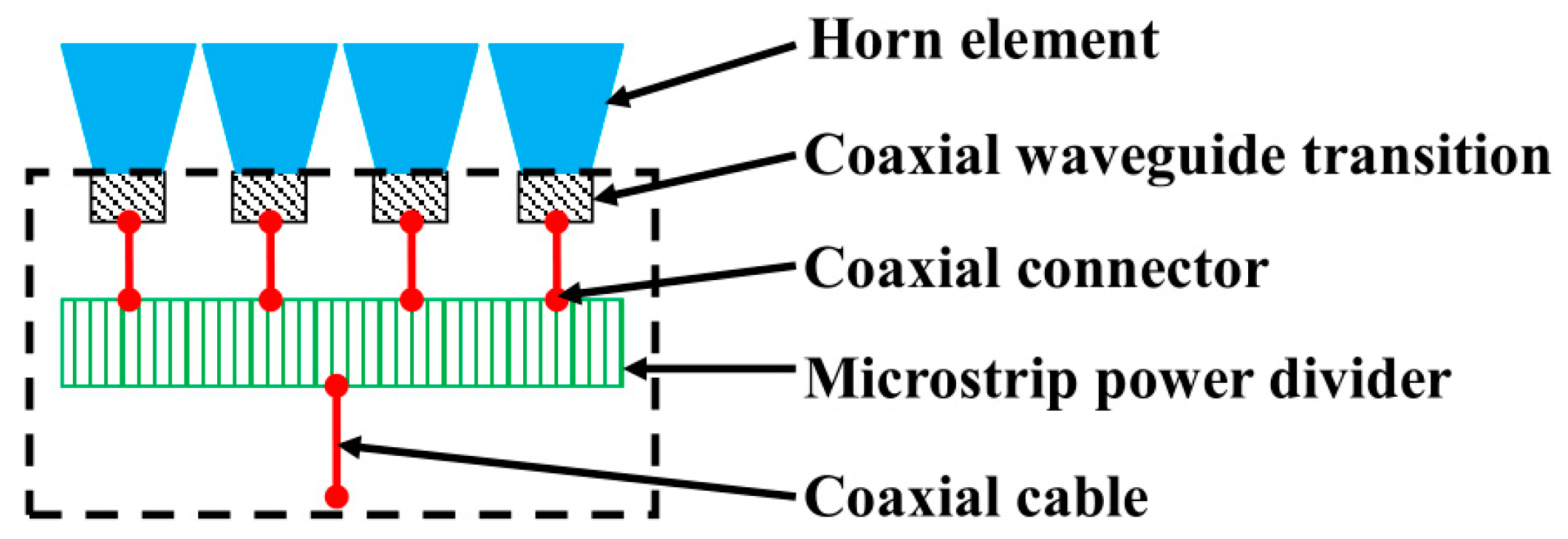
3. Theoretical Analysis and Design of the Power Dividing Horn Subarray

3.1. Traditional Y-Junction Structure

The H-T junction (i.e., a T-junction in the H-plane) is a waveguide that is divided into a two-way waveguide in the H-plane [18,23]. The Y-junction is a more compact structure than an H-T junction in applications, and is shown in Figure 8. When the TE10 wave was transmitted into port 1, the equal-amplitude and phase TE10 wave was output from port 2 and port 3. Therefore, the Y-junction is suitable as a power divider and combiner. Due to the two branches being folded in the same direction, the transition section between the main waveguide and branch waveguides will widen. This structure would lead to higher order modes (e.g., the TE20 mode), thus the matching becomes worse. The width design of the transition section is important, as it will suppress the higher order modes and broaden the bandwidth [24,25].

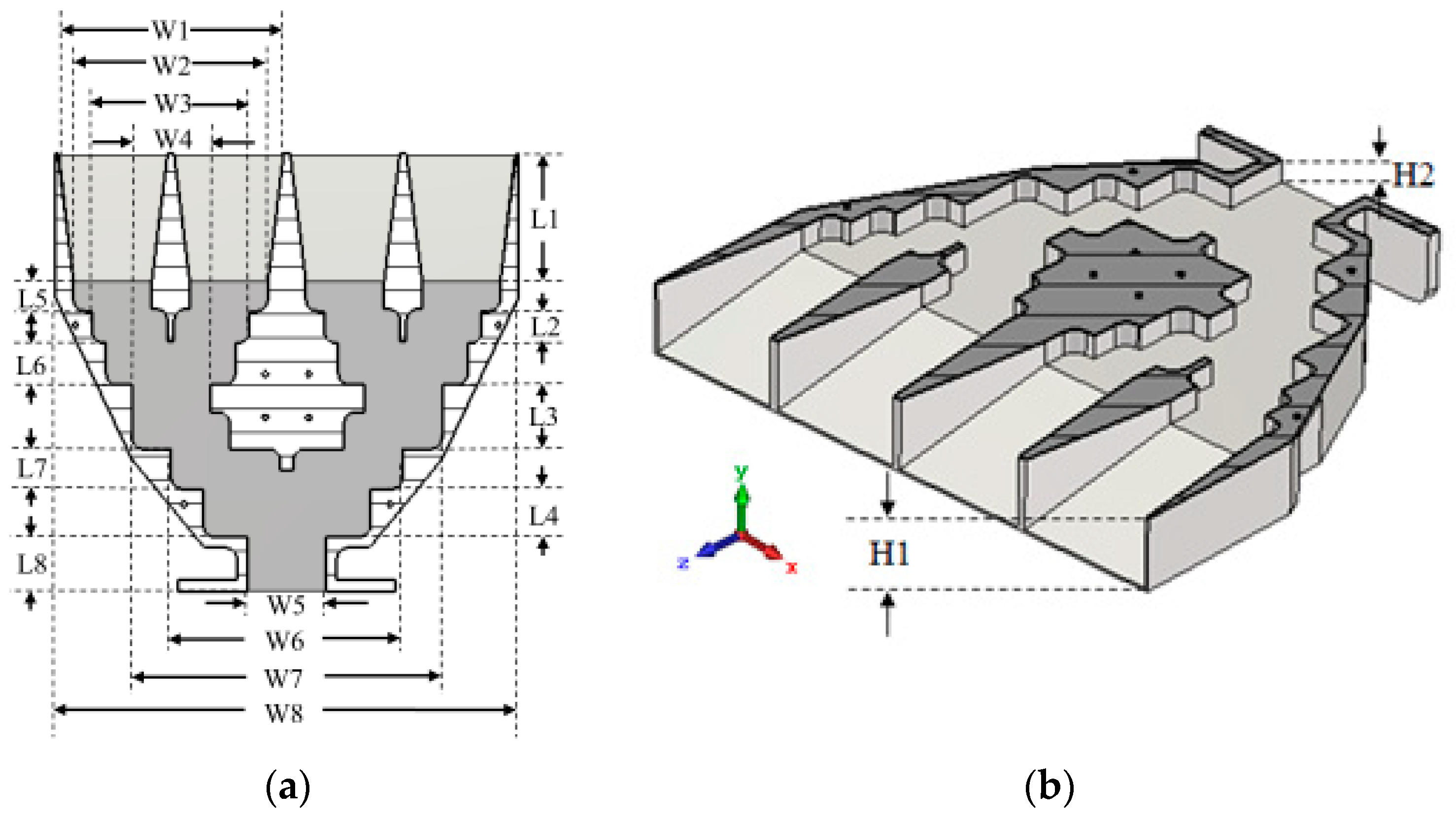
3.2. The Design of Power Dividing Horn Subarray

The structure of the power dividing horn subarray is shown in Figure 9. The power dividing horn subarray is achieved by cascading four pyramidal horn antennas and three H-plane Y-junction waveguide power dividers, thus, achieving the four equal-amplitude and phase outputs. The connector of the Y-junction waveguide power divider is WR-284, and it could operate from 3.4 GHz to 3.6 GHz. Initially, two types of two-way Y-junction waveguide power dividers with different branch spacing (i.e., 1.25 λ0 and 2.5 λ0) had been designed. Then, the two branch ports of the large spacing power divider should be connected to the main ports of two small spacing power dividers, and the splitters should be re-optimized. Finally, four pyramidal horn antennas were connected to the branch ports of two small spacing power dividers, and the length of horn antennas should be optimized. Furthermore, the subarray gets the matching without matching pins and just by thin splitters with rectangle heads, and the subarray is realized by six stepped waveguide transmission lines with a compact size of 4.89 λ0 × 4.97 λ0.
In order to reduce the reflection, multistage waveguides were employed to obtain a better match. Meanwhile, the gradual matching waveguide suppressed the emergence of higher order modes. The pyramidal horn antennas were highly integrated with the power dividers, and the assembly errors that were introduced by the flange could be calibrated. This was accomplished by segmenting the subarray into two identical parts along the xoz-plane. The pyramidal horn antennas and power dividers had been processed integrally by a milling machine, and the two identical parts were interlocked conveniently. The model was simulated with CST Microwave Studio, and the dimensions are listed in Table 2.

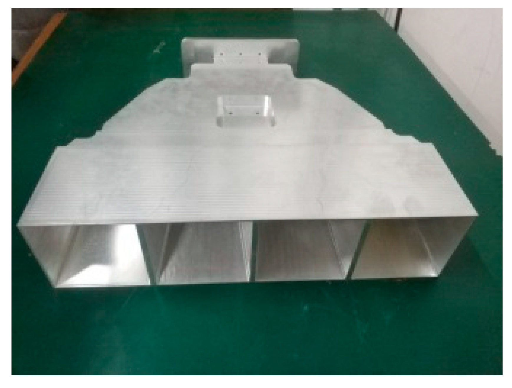
4. Simulation and Measurement Results

The simulated aperture electric field distributions are shown in Figure 10. The aperture electric field distributions of the four antenna elements were almost the same, but the differences of aperture phase distributions were more obvious. The peak amplitude imbalances of electric field in the middle cross section of y-axis were less than 0.5 dB, and the peak phase imbalances of the electric field were less than 3°. The prototype of the subarray is shown in Figure 11. The subarray is made of aluminum because of it is low weight and easy to process.
The results of VSWR are shown in Figure 12. Although the measurement results were higher than the simulated results, the matching of the subarray is good enough for application. The pattern at 3.5 GHz in the xoz-plane is shown in Figure 13, and the simulation results almost coincide with the measurement results in wide angles.

5. Conclusions

The effects of feed errors for near-field radiation characteristics of a subarray with a traditional power divider network are presented in this paper, and several conclusions are derived, as follows.
(1) Phase errors have more serious effects than amplitude errors.
(2) As phase errors increase, the amplitude and phase distributions show large deviations in some edge regions.
(3) The affected area is moved with the different observation distances z.
In order to reduce the cost and the calibration complexity of PWG greatly, adopting subarray design is critical. Due to the near-field radiation characteristics of subarray would be disturbed by feed errors. The high channel consistency requirement of subarray can be solved by compact waveguide power divider.
Typically, the maximum amplitude deviation of the quiet zone is less than 1dB and the maximum phase deviation is less than 10°. The feed amplitude and phase errors between different channels in one subarray cannot be calibrated, which have to be controlled at the manufacturing stage. The relationship between the feed errors of subarray channels and the quality of the quiet zone is analyzed in detail.
Based on the above rules, a novel compact power dividing horn subarray without intermediate pins was successfully designed and produced. The proposed subarray combines four pyramidal horn antennas and a compact 1:4 waveguide power divider. The pyramidal horn antennas and power dividers had been processed integrally by a milling machine, and the two identical parts were interlocked perfectly. The achieved amplitude difference between the four elements of the subarray is less than 0.5 dB, and the phase difference is less than 3°.

Author Contributions

Writing—original draft preparation, Z.Q.; Writing—review and editing, Z.Q., Z.W., J.M.; Investigation, Z.Q., Z.W. and J.M.; Measurement, Z.Q.

Funding

This work was supported by the National Science and Technology Major Project (2018ZX03001028).

Conflicts of Interest

The authors declare no conflict of interest.

References

  1. Dahlman, E.; Mildh, G.; Parkvall, S.; Peisa, J.; Sachs, J.; Selén, Y.; Sköld, J. 5G wireless access: Requirements and realization. IEEE Commun. Mag. 2014, 52, 42–47. [Google Scholar] [CrossRef]
  2. Li, Q.; Wei, Y.Y.; Tan, M.T.; Lei, X.; Wu, G.X.; Huang, M.Z.; Gong, Y.B. Flexibly Extensible Planar Self-Isolated Wideband MIMO Antenna for 5G Communications. Electronics 2019, 8, 994. [Google Scholar] [CrossRef]
  3. Siddiqi, M.A.; Yu, H.; Joung, J. 5G Ultra-Reliable Low-Latency Communication Implementation Challenges and Operational Issues with IoT Devices. Electronics 2019, 8, 981. [Google Scholar] [CrossRef]
  4. Bangash, K.; Khan, I.; Lloret, J.; Leon, A. A Joint Approach for Low-Complexity Channel Estimation in 5G Massive MIMO Systems. Electronics 2018, 7, 218. [Google Scholar] [CrossRef]
  5. Hassan, N.; Fernando, X. Massive MIMO Wireless Networks: An Overview. Electronics 2017, 6, 63. [Google Scholar] [CrossRef]
  6. Li, Y.; Wang, C.T.; Yuan, H.W.; Liu, N.; Zhao, H.L.; Li, X.L. A 5G MIMO Antenna Manufactured by 3-D Printing Method. IEEE Antennas Wirel. Propag. Lett. 2016, 16, 657–660. [Google Scholar] [CrossRef]
  7. Li, Y.; Xin, L.J.; Zhang, X. On Probe Weighting for Massive MIMO OTA Testing Based on Angular Spectrum Similarity. IEEE Antennas Wirel. Propag. Lett. 2019, 18, 1497–1501. [Google Scholar] [CrossRef]
  8. Qiao, Z.L.; Wang, Z.P.; Loh, T.H.; Gao, S.; Miao, J.G. A Compact Minimally Invasive Antenna for OTA Testing. IEEE Antennas Wirel. Propag. Lett. 2019, 18, 1381–1385. [Google Scholar] [CrossRef]
  9. Kyösti, P.; Fan, W.; Pedersen, G.F.; Latva-Aho, M. On Dimensions of OTA Setups for Massive MIMO Base Stations Radiated Testing. IEEE Access 2016, 4, 5971–5981. [Google Scholar] [CrossRef]
  10. Reed, D.; Rodriguez-Herrera, A.; Borsato, R. Measuring massive MIMO array systems using over the air techniques. In Proceedings of the 2017 11th European Conference on Antennas and Propagation (EUCAP), Paris, France, 19–24 March 2017; pp. 3663–3667. [Google Scholar]
  11. Fan, W.; Carton, I.; Kyösti, P.; Karstensen, A.; Jämsä, T.; Gustafsson, M.; Pedersen, G.F. A Step Toward 5G in 2020: Low-cost OTA performance evaluation of massive MIMO base stations. IEEE Antennas Propag. Mag. 2017, 59, 38–47. [Google Scholar] [CrossRef]
  12. Gillespie, E.S.; Hess, D.W.; Stubenrauch, C.F. Antenna measurements: A comparison of far-field, compact range and near-field techniques. In Proceedings of the Conference on Precision Electromagnetic Measurements Digest, Boulder, CO, USA, 27 June–1 July 1994; p. 375. [Google Scholar]
  13. Bucci, O.M.; Migliore, M.D.; Panariello, D.; Pinchera, D. Plane-Wave Generators: Design Guidelines, Achievable Performances and Effective Synthesis. IEEE Trans. Antennas Propag. 2013, 61, 2005–2018. [Google Scholar] [CrossRef]
  14. Zhang, X.H.; Zhang, Z.H.; Ma, Y.J. 5G Antenna system OTA testing with plane wave generator in range-constrained anechoic chamber. In Proceedings of the 2017 Sixth Asia-Pacific Conference on Antennas and Propagation (APCAP), Xi’an, China, 16–19 October 2017; pp. 1–3. [Google Scholar]
  15. Poordaraee, M.; Glazunov, A.A. Plane wave synthesis with irregular chamber planar antenna arrays for Compact OTA Measurements. In Proceedings of the 2019 13th European Conference on Antennas and propagation (EuCAP), Krakow, Poland, 31 March–5 April 2019; pp. 1–5. [Google Scholar]
  16. Wang, H.; Miao, J.G.; Jiang, J.S. A near-field planar array of pyramidal horn antennas for plane-wave synthesis. In Proceedings of the 2010 IEEE International Conference on Ultra-Wideband, Nanjing, China, 20–23 September 2010; pp. 1–4. [Google Scholar]
  17. Scattone, F.; Sekuljica, D.; Giacomini, A.; Saccardi, F.; Scannavini, A.; Gross, N.; Kaverine, E.; Iversen, P.O.; Foged, L.J. Design of dual polarised wide band plane wave generator for direct far-field testing. In Proceedings of the 13th European Conference on Antennas and Propagation (EuCAP), Krakow, Poland, 31 March–5 April 2019; pp. 1–4. [Google Scholar]
  18. Tsunemitsu, Y.; Matsumoto, S.; Kazama, Y.; Hirokawa, J.; Ando, M. Reduction of Aperture Blockage in the Center-Feed Alternating-Phase Fed Single-Layer Slotted Waveguide Array Antenna by E-to H-Plane Cross-Junction Power Dividers. IEEE Trans. Antennas Propag. 2008, 56, 1787–1790. [Google Scholar] [CrossRef]
  19. Deng, J.; Wang, Q.Y.; Zhao, P.; Tian, M.J.; Li, Q.S. A Quasi-Planar H-Plane Waveguide Power Divider with Full Bandwidth. IEEE Microw. Wirel. Compon. Lett. 2018, 28, 645–647. [Google Scholar] [CrossRef]
  20. Sun, X.L.; Wang, Z.P.; Miao, J.G. Near Field Quasi Plane Wave Generation and Performance Evaluation. In Proceedings of the 2018 Asia-Pacific Microwave Conference (APMC), Kyoto, Japan, 6–9 November 2017; pp. 917–919. [Google Scholar]
  21. Xie, R.S.; Wang, X.; Wang, R.W.; Wang, T.L.; Chen, D.; Song, T.; Zhu, K.S. Synthesis of plane wave applied to 5G communication antenna measurement. In Proceedings of the 2017 Progress in Electromagnetics Research Symposium—Spring (PIERS), St. Petersburg, Russia, 22–25 May 2017; pp. 195–198. [Google Scholar]
  22. Brockett, T.J.; Rahmat-Samii, Y. Subarray Design Diagnostics for the Suppression of Undesirable Grating Lobes. IEEE Trans. Antennas Propag. 2012, 60, 1373–1380. [Google Scholar] [CrossRef]
  23. Sehm, T.; Lehto, A.; Raisanen, A.V. A large planar 39-GHz antenna array of waveguide-fed horns. IEEE Trans. Antennas Propag. 1998, 46, 1189–1193. [Google Scholar] [CrossRef]
  24. Ding, Y.; Wu, K. T-Type Folded Substrate Integrated Waveguide (TFSIW) Slot Array Antenna. IEEE Trans. Antennas Propag. 2010, 58, 1792–1795. [Google Scholar] [CrossRef]
  25. Li, T.; Chen, Z.N. A Dual-Band Metasurface Antenna Using Characteristic Mode Analysis. IEEE Trans. Antennas Propag. 2018, 66, 5620–5624. [Google Scholar] [CrossRef]
Figure 1. OTA testing scenario of PWG.
Electronics 08 01148 g001
Figure 2. Schematic diagram of the subarray based PWG.
Electronics 08 01148 g002
Figure 3. Schematic diagram of the subarray 1 with a traditional power divider network.
Electronics 08 01148 g003
Figure 4. Simulation model of the subarray 1.
Electronics 08 01148 g004
Figure 5. Effects of errors 1 on the near-field distributions: (a) the amplitude distributions; (b) the phase distributions.
Electronics 08 01148 g005
Figure 6. Effects of different phase errors on the near-field distributions: (a) the amplitude distributions; (b) the phase distributions.
Electronics 08 01148 g006
Figure 7. Effects of phase errors on the near-field distributions in different distances z: (a) the amplitude distributions; (b) the phase distributions.
Electronics 08 01148 g007
Figure 8. Structure of the Y-junction in the H-plane.
Electronics 08 01148 g008
Figure 9. Cross-section views of the power dividing horn subarray: (a) top view; (b) perspective view.
Electronics 08 01148 g009
Figure 10. Aperture electric field distributions at 3.5 GHz: (a) the amplitude distributions of the two-dimensional electric field; (b) the phase distributions of the two-dimensional electric field; (c) the amplitude distributions in the middle cross section of the y-axis; (d) the phase distributions in the middle cross section of the y-axis.
Electronics 08 01148 g010
Figure 11. Prototype of the subarray.
Electronics 08 01148 g011
Figure 12. Simulated and measured VSWRs.
Electronics 08 01148 g012
Figure 13. Pattern at 3.5 GHz for the xoz-plane.
Electronics 08 01148 g013
Table 1. Estimated feed error and near-field observation position of subarray 1.
CaseAmplitude Error (dB)Phase Error (°)Observation
Position in z-axis (m)
E1E2E3E4E1E2E3E4
1000000002
20.9200.720.450520132
30.9200.720.4500002
400000520132
500000515202
600000202002
700002000202
800000200202
900000196152
10000000001
1100002000201
12000000001.5
1300002000201.5
Table 2. Dimensions of the power dividing horn subarray.
ParametersmmParametersmm
W1208.28L229.5
W2179.28L359
W3145.28L444
W472.14L527
W572.14L638.5
W6213.42L737
W7286.42L850
W8426.56H152.55
L1118H217.02

