Abstract
The interconnection of different electronic devices or systems through cables is becoming more difficult due to the hard restrictions related to electromagnetic compatibility (EMC) in order to comply with requirements. Therefore, the use of EMC components is a good solution to manage the problems associated with the filtering of electromagnetic interference (EMI) in cables and to pass the compliance test. In this sense, sleeve ferrite cores become a very interesting solution since they can be set around a wire and, hence, they provide an effective solution against EMI without having to redesign the electronic circuit. This contribution is focused on the characterization of the performance of a sleeve ferrite core based on a novel nanocrystalline (NC) novel material for EMI suppression and comparing it to the most conventional ceramic ferrite cores such as MnZn and NiZn. The research highlights the suitability of an NC novel component in terms of its magnetic properties to reduce EMI within the conducted emissions range. This range is generally defined by the International Special Committee on Radio Interference (CISPR) test standards frequency band that covers from 150 kHz up to 30 MHz (108 MHz in the case of CISPR 25). First, this study presents a description of the main parameters that define the behavior of NC and ceramic cores and, secondly, by analyzing the data obtained from experimental procedures, it is possible to directly determine the insertion loss parameter. Hence, this characterization procedure is used to obtain the performance of NC material compared to the conventional sleeve ferrite core compositions employed to filter the interferences in this problematic frequency range. As can be deduced from the results obtained, an NC sleeve ferrite core provides the best performance in terms of EMI filtering within a significant frequency range between 100 kHz and 100 MHz.
1. Introduction
The fast development of electrical and electronic products has become an increasingly serious electromagnetic interference (EMI) problem faced by engineers and scientists [1]. This situation intensifies the presence of interference generated by electromagnetic fields; therefore, it is becoming increasingly difficult to ensure all devices operate simultaneously in the context of electromagnetic compatibility (EMC) without inferring with each other [2].
EMI can be one of the main causes that generates the degradation (performance-wise) of an electronic system; this usually occurs at frequencies that are higher than the signals traveling the circuit. The most common sources of these interferences include natural ones (such as atmospheric electrical phenomena), power lines, auto ignition or radio frequency (RF) interference.
In terms of the kind of disturbance that is transmitted, EMI is divided into two categories: conducted and radiated emissions; regarding the way the electromagnetic field is propagated. In the case of radiated EMI, it is caused by induction whereas conducted EMI is generated by physical contact of conductors. Thus, in the low frequency range EMI is generally emitted via conduction and, in the high frequency region via radiation. Likewise, conducted EMI can be classified into two kind of currents in terms of different directions of leading: differential mode (DM) and common mode (CM) [3]. In the correct working of a circuit, a differential current is designed to flow in order to obtain a clear signal. When opposing currents are created and flow in the same direction as the intended current, the differential intended currents are canceled. In CM, currents flow in both conductors in the same direction and are not suppressed as they are non-intentional (EMI) currents [4,5].
This contribution is focused on the filtering of conducted EMI in which the upper limit is specified by CISPR-based test standards (CISPR 11, 14-1 and 32) up to 30 MHz, except for CISPR 25, where the applicable upper frequency extends to 108 MHz [6]. In particular, the most common EMI sources that interfere in the conducted range are switch-mode power converters [7]. Both embedded DC–DC converters are intended for a large number of commonly used electronic devices [8] and high–low voltage DC–DC converters employed to charge Electric Vehicle batteries [9] contribute to the generation of EMI in this frequency band. In order to avoid, or at least reduce EMI, suppressors should work as low-pass filters, suppressing signals with frequencies higher than the intended signal frequency value [1]. Nowadays, most electronic products are connected to the main power network or are designed to be interconnected with others through cables. These cable interconnections are becoming more difficult due to the hard restrictions related to the accomplishment of EMC compliance. Thereby, the use of EMC components is a good solution to manage the problems linked to the EMI filtering in cables and pass the compliance test. In this sense, sleeve ferrite cores (also known as cable ferrites) are a very interesting solution since they can be set around a wire and provide an effective solution against EMI without having to redesign the electronic circuit. These components are widely used in EMI filtering applications because they are usually applied to be set on power cables or peripheral cables of electronic devices in order to prevent electromagnetic disturbance that could be propagated along the wire, as shown in Figure 1 [10,11]. This filtering method enables limiting of the conducted emissions [12,13] and can be applied in electronics and telecommunications elements [2,7,14]. Therefore, when a disturbance current is flowing in the peripheral and/or power wires connected to the device, the manufacturer usually decides to attach a sleeve ferrite core to encircle these cables. This is due to the fact that the sleeve ferrite core introduces a certain insertion loss (A) by which the disturbance current flowing through it is reduced and, therefore, EMI is attenuated [15]. Furthermore, these cores are ideally suited for reducing the EMI interferences because they are very effective against CM currents [4,10].
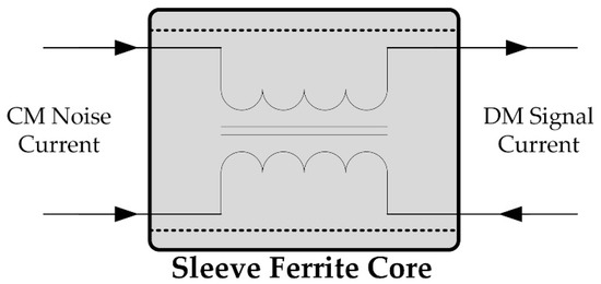
Figure 1.
Diagram of common mode (CM) and differential mode (DM) currents passing through a ferrite core.
The mechanism used by a sleeve ferrite core to filter electromagnetic noise is the increase of the cable impedance in those frequencies that can hold disturbances. When a ferrite core encircles a conductor lead it should pass the intended signal frequency and should block the EMI frequency components. Thereby, a sleeve ferrite core is able to manage the line impedance through its magnetic properties, providing a low impedance to the intended signal and increasing the conductor impedance for suppressing interferences within a specific frequency spectrum. The material and production technique used to make a ferrite core defines its magnetic properties and determines the frequency range of suitability. Conventionally, ferrite core materials for EMI suppression are based on MnZn and NiZn and their combinations [16,17,18]. The use of MnZn sleeve ferrite cores is generally centered on the range that covers from some hundreds of KHz to some MHz, in contrast to ferrite cores made of NiZn material that works in a broadband frequency range that can cover from tens of MHz up to several hundreds of MHz [4]. The results presented in [19] highlighted the great suitability of NC cable ferrite to filter electromagnetic interference in a low-frequency region. Furthermore, data obtained from its magnetic properties indicate that this EMC solution could also provide good performance in terms of EMI suppression at higher frequencies. In this sense, some researchers have investigated the use of NC structure compositions to make EMC components because this kind of core can reduce its volume by 50–80% and can yield greater magnetic properties and insertion losses compared to other sleeve ferrite cores [20,21,22,23].
Consequently, a prototype of the novel NC structure is characterized in relation to MnZn and NiZn conventional ceramic cores with the aim of determining the effectiveness of this novel material compared to the current solutions in the conducted frequency range. This is firstly presented in Section 2 by defining the magnetic properties of each material through measuring the relative permeability parameter. Subsequently, Section 2 also describes the performance of NC sleeve ferrite core compared with the ceramic cores from the point of view of the magnitude of the impedance and its complex components since this is the parameter most used by manufacturers to describe the performance of a sleeve ferrite core. In Section 3, the experimental setup designed to simulate a system with conducted emissions problems is described. This measurement procedure is used to determine the attenuation ratio that NC, MnZn and NiZn sleeve ferrite cores are able to offer in the frequency region between 100 kHz to 200 MHz. In Section 4, the data obtained from magnetic properties of the three different cores and the impedance measured are compared with the data obtained from the experimental measurement setup. This step is carried out in order to verify that the data obtained by the three different procedures match and, thus, it is ensured that they are properly acquired, since some investigations conclude that the measurement of the impedance parameter is not accurate from a certain frequency value [24,25,26]. It is essential to obtain an actual and verified impedance value because this parameter is employed as a reference to determine the accuracy of the experimental measurement setup employed to obtain the EMI suppression ability in terms of decibel for each sleeve ferrite core. Furthermore, Section 4 compares the results based on the insertion loss parameter of an NC core and ceramic ones, as well as extrapolating the results considering systems with different impedances to show the dependence of the filtering performance with the impedance of the system where the sleeve ferrite core is introduced [27]. Finally, important conclusions regarding the frequency ranges where NC is more suitable than ceramic sleeve ferrite cores are summarized in Section 5, in order to establish the extent to which NC suppresses those conducted EMI problems that current ceramic sleeve ferrite cores are unable to solve.
2. Sleeve Ferrite Core Characterization
Sleeve ferrite cores are manufactured from a magnetic material that allows them to control RF noise in cables and reduce it at a certain frequency range. This range mainly depends on their intrinsic composition and internal structure. Ferrite cores belong to the ferromagnetic materials field and can be categorized into three groups: ceramics, composite materials and metals. Conventionally, the most used sleeve ferrite cores are based on ceramic materials such as MnZn and NiZn, whereas the NC core characterized in this research is included in metals. Ceramics are also known as polycrystalline materials because they can contain metal oxides, such as manganese or zinc oxide. The features that have made ceramics the most popular filtering solution are their strong adhesion forces, heat-resistance, hardness and high resistance to pressure. One of the main advantages of the ceramics is the possibility of manufacturing filtering components with many different shapes. In contrast to ceramics, currently, the manufacture of NC cores with different shapes is complicated due to the fact it is not a simple solid core. NC cores are formed by metal film layers that are rolled up to reach the desired size. This shape cannot be cut safely without undermining its EMI suppression ability because when the core is cut, small shortcuts are caused between the layers, lowering the magnetic properties of the core. Therefore, it is difficult to create snap ferrite cores that can be clamped on a cable because they are not a solid core. Nevertheless, the structure of the novel NC material presents the advantage of designing smaller components with greater magnetic properties for low-frequency applications due to its intrinsic properties which are obtained by means of its complex manufacturing procedure [19]. This process consists of melting the material by heating it at 1300 °C. Next, the liquid is deposited on a wheel in order to cool it through spinning around at 100 km/h with the aim of reducing its temperature at a cooling rate of 106 K/s. Thereby, the amorphous structure is generated and the thickness of the film is defined. Thereafter, the film is rolled up to form the sleeve core and it is exposed to an annealing process where it is warmed up to 600 °C to achieve the nanocrystalline structure. Finally, strong magnetic fields are applied to the material in order to get greater magnetic properties. Hence, from comparing its magnetic properties to those provided by ceramic cores, it is possible to consider that NC can not only provide a high attenuation ratio in the ultra-low frequency range (9 kHz to 150 kHz) but also, it could be more effective than ceramic cores throughout an upper frequency range.
When an electrical conductor carrying a certain current is inserted through a sleeve ferrite core, it produces a magnetic field. Sleeve ferrite cores are designed to absorb the magnetic field, inducing currents, into its internal structure. These currents, known as eddy currents [28], are dissipated by the core as heat and they mainly define the loss ability of the component. Eddy currents can fluctuate depending on the strength of the field, frequency and material grain size [29].
The evaluation of the novel NC sleeve ferrite core is carried out by analyzing the performance regarding two kinds of ceramic cores, with the aim of analyzing the frequency range where NC is more effective at suppressing conducted EMI. One of the cores selected is based on MnZn, a material widely used to reduce EMI in the low-frequency region and the other selected core is made of NiZn that is generally employed to filter EMI from some tens of Megahertz. Thus, it is important that the analyzed sleeve ferrite cores have a similar volume. One of the most significant parameters of a sleeve ferrite core is the height or length of the core since the electromagnetic absorption ratio varies only the log of the division between the external and the internal diameter, but is directly related with the length [4]. Accordingly, the ceramic MnZn and NiZn sleeve ferrite cores characterized in this contribution have been selected as they have dimensions similar to the manufactured novel NC core prototype. These parameters are shown in Table 1.

Table 1.
Lists of sleeve ferrite cores used in this research.
2.1. Magnetic Properties
One of the most important parameters that defines the ability of a material to absorb electromagnetic interferences is the relative permeability () [13]. The permeability relates the magnetic flux density of a certain magnetic field in a defined medium, so that when a sleeve ferrite core is placed around a certain cable, the magnetic flux is concentrated in it. This ability to concentrate the magnetic flux is described by the material’s internal properties and it is represented through the permeability complex parameter. The losses of the magnetic flux can be determined by dividing it into its complex form; in this way, the real component () quantifies the real or inductive part and the imaginary or resistive component () is related to the material ability to absorb the electromagnetic interferences [30,31]. Thereby, the complex relative permeability is expressed by:
One governing rule of EMI suppression that relates the permeability to the frequency in powder ferrite cores is Snoek’s Law [4] given by (2):
where corresponds to the ferromagnetic resonance frequency, is the magnetic saturation and the initial permeability. This last parameter is measured at low frequency (usually at 10 kHz with a temperature of 25 °C) and it is used for manufacturers to organize the filtering ability of cable ferrites. Equation (2) shows that the higher the frequency of operation, the lower the permeability, and vice versa. Thus, if the material provides high initial permeability, the frequency fall off will be low and vice versa. For this reason, MnZn ferrite cores are normally focused on the high kHz or at most, the very low MHz region since this material yields an initial permeability value between 3000–10,000 [32,33]. With regard to NiZn materials, they usually provide an initial permeability that varies between 500–1200, so they are able to more effectively filter electromagnetic noise within a high-frequency range [34,35]. Otherwise, the NC material shows a much higher initial permeability than ceramics due to its internal structure and manufacturing process that improve its magnetic properties. This results in an important increase in the initial permeability, reaching values of nearly 100,000 [22].
The magnitude of the relative permeability of the NC material is represented together with MnZn and NiZn permeability traces in Figure 2 to study the frequency region covered by each material [10]. This graph shows that from the point of view of the magnetic properties, the NC core, despite being the material with higher initial permeability provides higher permeability than the ceramic materials throughout almost the entire frequency range studied. MnZn is able to provide a permeability around 3000 up to the 2 MHz point, providing a similar value to NC at this frequency point. In the high-frequency region, NC demonstrates a better performance than NiZn although it is possible to observe how the slope of NC is greater and, thus, NiZn may be more effective. In this way, the NC core, despite being the material with a higher initial permeability, provides higher permeability than the ceramic materials throughout the frequency range studied.
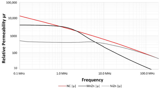
Figure 2.
Relative Permeability of nanocrystalline (NC) compared with MnZn and NiZn sleeve ferrite cores compositions.
More information about the sleeve ferrite cores analyzed can be obtained by splitting into real and imaginary components the complex relative permeability of the three materials. These traces allow one to determine the magnetic resonance frequency () of each material, as shown in Figure 3. This corresponds to the frequency value at which the real part of the relative permeability begins to fall and the imaginary part reaches the maximum peak [36]. Generally, the inductance component is steady below the and decreases significantly from this frequency value [24]. The NC minigraph shows the lower frequency value at which the takes place; however, the absorption loss represented by the imaginary part shows the weakest slope, if it is compared with MnZn and NiZn imaginary traces. From this information, together with the fact that NC provides a higher initial permeability, results in this sleeve ferrite solution could yield a greater attenuation ratio in a wider frequency range than ceramic cores. The equipment used to carry out these relative permeability measurements is based on the E4991A Material Analyzer (Keysight, Santa Rosa, CA, USA) that is interconnected with the 16454A Magnetic Material Text Fixture. This fixture measures accurately the permeability parameter of round-shaped magnetic materials because its features emulate one turn winding the core without magnetic flux leakage. Consequently, direct readouts of the complex permeability are obtained.
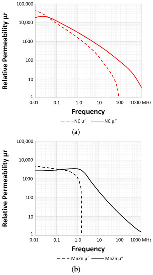
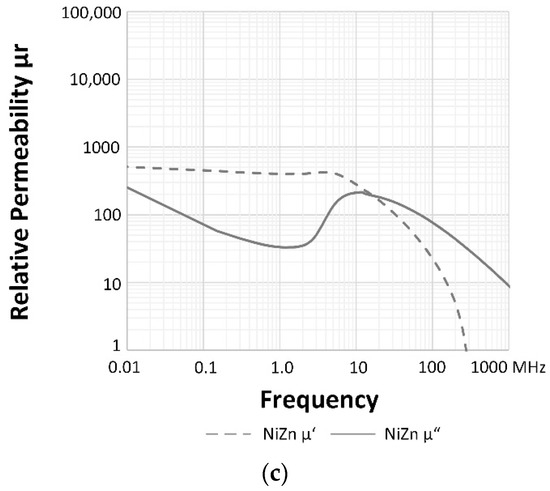
Figure 3.
Complex relative permeability split into real and imaginary components: (a) NC sleeve ferrite core; (b) MnZn sleeve ferrite core; (c) NiZn sleeve ferrite core.
There is also a capacitance component that represents the dielectric effects of the ferrite magnetic material. This appears in the bandwidth above the , where the inductive component of the permeability becomes negative [13,37]. As can be observed in Figure 3, this stray capacitance due to the magnetic material is noted beyond 1.8 MHz and 85.1 MHz and 282.7 MHz in case of MnZn, NC and NiZn cores, respectively.
2.2. Impedance and Phase Description
Although the permeability parameter is used to describe the behavior of the core material, the performance of a certain sleeve ferrite core takes into account, besides the material features, other variables such as the self-inductance defined by the dimensions and the shape. Thereby, sleeve ferrite cores are usually defined and classified through specifying the magnitude of the impedance (ZF), which is obtained from the equivalent component parameters such resistance (R) and inductance (L) [4,27]. The magnitude of the impedance is given by:
where R corresponds to the equivalent resistance and XL is the impedance of the inductive part of the sleeve ferrite core. The vector relationship between impedance and permeability components is shown in Figure 4.
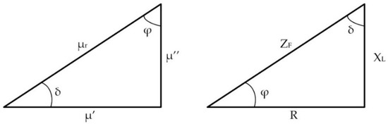
Figure 4.
Vector relationship between , , and (left); vector relationship between ZF, R and XL (2πfL) (right).
There is a proportional relation between the attenuation ratio or insertion loss provided by a certain sleeve ferrite core and the impedance of the system where it is set. Thus, it is essential to select a sleeve ferrite core that provides an impedance value that is higher than the system impedance at the frequency to be filtered. This is due to the fact they are more effective when they are used on cables connected to circuits with low impedance [5]. Sometimes it is difficult to accurately determine the impedance of the system with EMI problems; however, depending on the kind of lead, it is possible to estimate this value: for instance, ground leads usually present between 1 and 2 Ω, supply voltage lines have impedances from 10 to 20 Ω and video, clock and data lines from 90 Ω to 150 Ω [27].
A sleeve ferrite core can be represented by a simplified equivalent circuit consisting of an inductance, a resistance and a capacitance, as shown in Figure 5. This circuit represents a sleeve ferrite core within the frequency range analyzed in this contribution without taking into consideration the system where it could be placed, since the surrounding elements may introduce additional parasitic effects. The behavior of the sleeve ferrite core at a low-frequency range is usually mostly inductive, blocking CM currents due to its inductive reactance (LF). The impedance becomes more resistive (RF) as the frequency is increased, absorbing and dissipating CM currents as heat. Hence, LF and RF are the predominant components below the ferromagnetic resonance frequency; however, from this frequency value, the stray capacitance of the ferromagnetic material becomes predominant, defining the fall slope of the impedance. Regarding CF, it represents a parasitic capacitance because of the winding effect [24]. When a sleeve ferrite is set around a cable, it is equivalent to one turn or one winding coil. An interesting feature of sleeve ferrite cores is the possibility of winding the wire around them multiple times, considering each pass of the cable through the sleeve core as one turn. This technique results in an increase of the ferrite impedance proportionally to the number of turns squared. Nevertheless, increasing the number of turns also increases the winding capacitance CF, shifting the point of maximum impedance to a lower frequency value [25]. Therefore, there is a balance between the number of turns and winding capacitance, because a higher number of turns implies a worse performance at high frequencies. Nevertheless, increasing the number of turns N, it is possible to increase to obtain a higher inductance LF value, but at the same time, the stray capacitance CF increases [13]. This last fact could generate a self-resonance (SRF) at a certain frequency. Above the value of the SRF, the impedance becomes predominantly capacitive and the effectiveness of the sleeve ferrite core to filter EMI is degraded [38,39]. Therefore, SFR due to CF could superpose the ferromagnetic resonance due to the intrinsic material parameters described above. This is one of the main reasons why more than two or three turns are not usually used. In this contribution, the characterization is carried out by winding one and two turns in the sleeve ferrite cores.
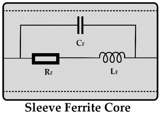
Figure 5.
Simplified sleeve ferrite core equivalent circuit.
The measurement setup currently in use by manufacturers for characterizing a sleeve ferrite core is based on the measurement of its impedance by means of introducing along the core a wire with a defined length and cross-section, which is connected to an Impedance Analyzer. The wire selected should be as short as possible, but long enough to achieve one and two turns around the sleeve ferrite core. With this conventional method, the influence of the wire in the total impedance measured can only be neglected if its length is short compared to the wavelength and this limit is usually a least 1/10 of the wavelength (λ). Some investigations have evaluated this measurement method and agree that it is not sufficiently accurate for very high frequency characterizations, because if an AWG26 (American Wire Gauge) cable is used, the minimum length required to wind two turns around the NC sleeve ferrite core is 150 mm. As a result, the maximum frequency that can be measured is 200 MHz (following the restriction of λ/10). If this procedure is used to characterize sleeve ferrite cores from 200 MHz, the wire represents a series inductance whose value becomes higher as the wire length increases. At the same time, this length increase causes the SRF to shift to a lower region, considering not only the impedance of the core but also the impedance introduced by the cable [25,26]. In the case of winding only one turn around the sleeve ferrite core, it is possible to use an AWG26 cable with a length of 70 mm with the aim of reducing the influence of the cable in the total impedance measurement. Figure 6 shows the impedance of both AWG cables used to determine the impedance of the sleeve ferrite cores. From these traces, the magnitude of the impedance provided by the two cables employed to measuring the impedance of the sleeve ferrite cores can be observed. It is important to take this fact into account, especially in those sleeve cores whose impedance can be similar to the impedance provided by the cable.
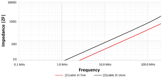
Figure 6.
Magnitude of the impedance of the AWG26 (American Wire Gauge) wires used to measure the impedance of the sleeve ferrite cores.
Subsequently, considering these conditions, a calibration procedure has been performed with the aim of reducing the influence of the AWG cable, especially in the frequencies closer to the (λ/10) limit, when the 150 mm cable is employed. Taking this fact into consideration, it is possible to determine the direct impedance measurement through the E5061B Vector Network Analyzer (Keysight, Santa Rosa, CA, USA) connected to the Terminal Adapter 16201A (Keysight, Santa Rosa, CA, USA) and the Spring Clip Fixture 16092A (Keysight, Santa Rosa, CA, USA) [40]. These fixtures are internally compensated by impedance standard calibration in order to take into account the electrical length path and the impedance variations caused by parasitic elements. The measurements of R and XL obtained from the three sleeve ferrite cores with this setup are shown in Figure 7. Figure 7a shows the magnitude of the impedance measurement in which the most effective range of EMI suppression in the NC sleeve ferrite core compared to the ceramic cores analyzed can be observed. This minigraph shows that MnZn provides the higher impedance from 0.88 MHz to 2.73 MHz and NiZn offers a more effective behavior from 91.61 MHz, whereas in the rest of the frequencies, NC sleeve ferrite yields the best performance. If this data is compared to the permeability traces, it is possible to observe a correlation between both characterization methods, since MnZn provides a greater response than NC within a similar frequency region, which is shown in the permeability graph. With regard to the comparison between the NC and NiZn sleeve ferrite core, NC shows a higher impedance value of up to 91.61 MHz. At this frequency value, the inductance component of the analyzed NC sleeve ferrite core reaches negative values that match the SRF point. Consequently, the capacitive component of the core generates a degradation in the impedance performance, reducing it sharply with respect to NiZn sleeve ferrite core. In Figure 7b–d, the resistive (R) and inductance (XL) components can be observed in order to know the contribution of each of them related to the total impedance. As described above, the studied sleeve ferrites show higher values of XL within the low-frequency region; however, these become less important as the frequency increases if compared to the R component. The resonance frequency of MnZn and NC cores is located at 2.02 MHz whereas the resonance frequency of NiZn is located above 200 MHz.
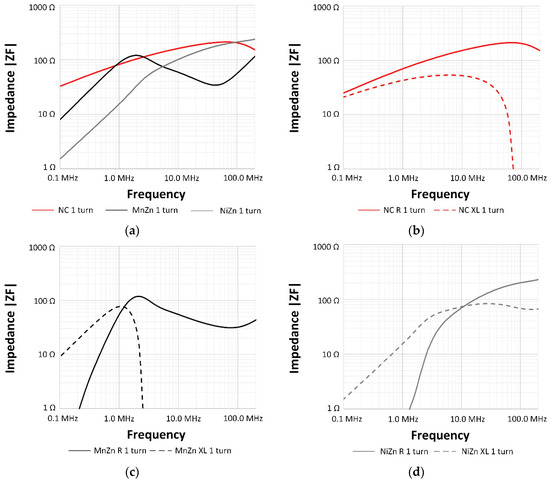
Figure 7.
Impedance measurements of the NC, MnZn and NiZn sleeve ferrites winding around them 1 turn: (a) Magnitude impedance of three cable ferrites; (b) NC R and XL impedance components; (c) MnZn R and XL impedance components; and, (d) NiZn R and XL impedance components.
The impedance traces obtained by winding two turns into the sleeve ferrite cores are shown in Figure 8. The increase of the number of turns generates higher values of the impedance magnitude in the three traces and causes a shift in the cross points of different sleeve ferrite traces. Therefore, NC provides the best performance up to 0.76 MHz, as well as in the frequency region from 2.75 MHz to 68.10 MHz. If the 10 MHz frequency point is taken as a reference, the values of the three traces have been increased about four times (the number of turns squared). Specifically, in the case of NC from 159.9 Ω to 651.2 Ω, MnZn 55.3 Ω to 227.0 Ω and NiZn cable ferrite from 100.9 Ω to 415.9 Ω.
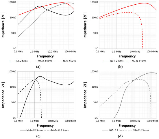
Figure 8.
Impedance measurements of the NC, MnZn and NiZn sleeve ferrites after winding around them by two turns: (a) Magnitude impedance of three cable ferrites; (b) NC R and XL impedance components; (c) MnZn R and XL impedance components; (d) NiZn R and XL impedance components.
From this data, the phase angle, which is defined by the angle whose sine is XL/R (ϕ) can be represented. In this way, it is possible to determine the behavior of a certain sleeve ferrite core by means of studying its phase: when it corresponds to 90°, the ferrite core works as a pure inductor, whereas for 0°, it works as a pure resistor. If the phase reaches negative values, the sleeve ferrite core reduces its EMI suppression ability due to the fact that it is starting to show a capacitive and undesired behavior. Figure 9a shows the course of the phase angle of NC sleeve ferrite cores that can be used as a frequency response indication and it can be compared with the ceramic sleeve ferrite cores. Note that in the NC case, the phase angle goes from 68° to 0° in the frequency range 0.01–72.50 MHz for one turn and 0.01–33.13 MHz for two turns. NC becomes more resistive than the other sleeve ferrites at lower frequencies and the transition between inductive and resistive behavior is less abrupt, since the phase of MnZn goes from 90° to 0° in the frequency range 0.01–2.52 MHz, matching for one and two turns and, in the case of NiZn, it crosses 0° at 94.55 MHz for two turns and beyond this frequency point, for one turn. Thus, it is possible to observe the broadband effectiveness than can provide the NC sleeve ferrite core in relation to ceramic ones.
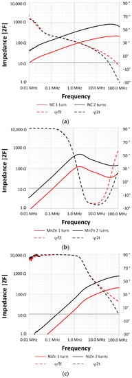
Figure 9.
Comparison of the magnitude impedance and angle phase of XL/R of the NC sleeve ferrite core compared to MnZn and NiZn by winding around them one and two turns: (a) NC sleeve ferrite core; (b) MnZn sleeve ferrite core; (c) NiZn sleeve ferrite core.
These graphs also allow one to determine from which frequency value the phase angle of each sleeve ferrite becomes negative and, therefore, the component shows a capacitive behavior. As it has been described, in the case of MnZn, this frequency value corresponds to the , whereas for NC and NiZn, it is possible to observe that the phase angle trace crosses 0° at a lower frequency value, which demonstrates their complex relative permeability traces. This effect is caused by the shift of the SFR due to two factors: (a) the stray capacitance added to the sleeve ferrite response when the cable is winding it and (b) due to the self-resonance produced by the sleeve ferrite core dimensions (with smaller cores of the same material, the SFR appears at a higher frequency value). Therefore, the impedance magnitude is increased by winding a higher number of turns around the sleeve ferrite core but, at the same time, the effective frequency range is reduced.
In order to validate the impedance used to characterize the novel NC and ceramic sleeve ferrite cores, in Section 4, this data is compared with the impedance calculated from the relative permeability through the quasi-static model from the real and imaginary permeability components and the dimension of the sleeve ferrite core [13]. Generally, this model can be used for evaluating cores up to the SFR, since beyond this frequency value, the static magnetic flux distribution can fluctuate. This deviation could be because the core dimensions, saturation, core losses, and frequency-dependent magnetic effects that are significant above the SFR are not being taken into account [24]. Equations (4) and (5) show the link between the material permeability and dimensions of the sleeve ferrite core with the impedance (inductance and resistance components):
where µ0 is the permeability of the air, is the inductance permeability component, is the loss permeability component of the sleeve ferrite, ℓ is the effective magnetic path length of a toroidal core (m), N is the number of turns of a cable to carry out the measurement, A corresponds to the toroidal core cross-sectional area (m2) and ω is the angular frequency.
3. Insertion Loss
The datasheets of sleeve ferrite core components generally only specify the impedance at several frequency points or the graph of the magnitude of the impedance in the frequency range where it is more effective. In contrast to this fact, other kind of EMC component datasheets, such as common-mode-chokes, show the attenuation ratio or insertion loss in terms of decibels (dB) that are able to provide. This is because the insertion loss that a sleeve ferrite core is able to yield is strongly dependent on the impedance of the system in which it is placed besides its own impedance response. Subsequently, the equivalent circuit approach to determine the insertion loss parameter of a certain sleeve ferrite core, has to consider the source impedance (ZA) and the load impedance (ZB) of the system with electromagnetic interference problems, as well as the impedance introduced by the ferrite core in that system (ZF) [27]. The equivalent circuit diagram employed to determine this impedances relation and analyze the effect of introducing a sleeve ferrite core into a certain system is shown in Figure 10.
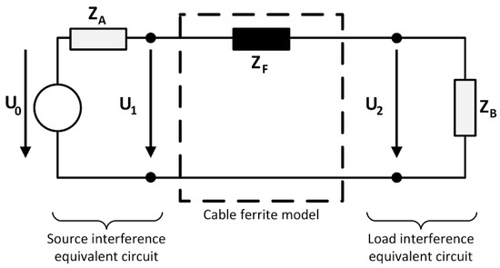
Figure 10.
Diagram of source and load equivalents circuits used to determine the insertion loss parameter of a sleeve ferrite core when it is introduced into a system.
According to this diagram, when the system impedance is known, the insertion loss (A) in terms of decibels can be calculated through the Equation (6) from the impedance of the sleeve ferrites (ZF) shows in Section 3:
It can be observed that for a given source and load impedances, increasing the impedance of the cable ferrite will increase the insertion loss. This theoretical insertion loss is used as a reference value to evaluate the experimental insertion loss measured through emulating the equivalent circuit diagram shown in Figure 10. In order to carry out the performance of the sleeve ferrite core, it is considered that the source and load impedance are known and the parameter of study is the impedance of the sleeve ferrite core. Therefore, an experimental measurement setup based on generating controlled EMI conducted emissions into a load with a stable impedance over the frequency range studied (from 150 kHz up to 200 MHz) to determine the insertion loss of the NC sleeve ferrite core and compare it with the insertion loss of ceramic cores. This setup takes as a reference the IEC 61000-4-6 standard (Testing and measurement techniques—immunity to conducted disturbances, induced by radio-frequency fields) and it consists of a continuous wave simulator (CWS) for testing conducted RF immunity within a frequency range from 100 kHz to 230 MHz that emulates the electromagnetic conducted interferences. This equipment is the CWS500N1 Continuous Wave Simulator (EM Test, Reinach, Switzerland) and it provides a 50 Ω output impedance that represents the ZA in the insertion losses equivalent circuit diagram. A coaxial cable connects the CWS500N1 to the CAL 801 (Ametek CTS, Reinach, Switzerland), which is employed to ensure a 100 Ω load in the whole analyzed frequency range. This impedance, together with the output impedance of the CWS500N1, represents a ZA = 150 Ω in the equivalent circuit diagram. The other side of this diagram is formed by another CAL 801 that provides a 100 Ω load that is connected to a spectrum analyzer N9010A (Keysight, Santa Rosa, CA, USA) with an input impedance of 50 Ω. Accordingly, the sum of these two impedances provides the impedance of ZB = 150 Ω. Both sides of the equivalent circuit emulated (A and B) are connected by means of an AWG26 cable of 150 mm, maintaining a distance of 35 mm from the ground metal layer that interconnects all the parts. This cable simulates a reference line that can be characterized and employed to introduce the NC and the ceramic sleeve ferrite cores into the setup to analyze how the emulated interferences are attenuated. Therefore, a previous calibration measurement is first carried out in order to ensure the stability and linearity of the system, generating a sinus frequency sweep with an amplitude of 140 dBµV. Once the reference signal is obtained, the sleeve ferrite core is introduced into the reference line of the insertion loss setup and the sinus frequency sweep is repeated. With these two measurements, it is possible to subtract them in order to obtain the attenuation rate or insertion loss performance of each of the sleeve ferrite cores and compare them in terms of decibels instead of impedance. Figure 11 shows the measurement setup described implemented inside an anechoic chamber.
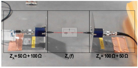
Figure 11.
Experimental measurement setup for characterizing NC and ceramic sleeve ferrite cores in terms of decibels.
4. Results and Discussion
This section is focused on analyzing the insertion loss measured with the experimental setup described above and comparing the performance of the novel NC sleeve ferrite core with those of MnZn and NiZn cores in terms of the attenuation ratio. As it has been explained, the characterization of sleeve ferrite cores in the high-frequency region presents some difficulties that can result in a reduction in the measurement accuracy beyond some tens of Megahertz. This is generally due to internal factors such as the influence of the measurement setup (length of the cable used as a reference line or the stability of the source and load impedances depending on the frequency) and external factors (isolation of external interferences). For this reason, firstly, a comparison between the data obtained mathematically from the magnetic properties and the impedance response measurement of the sleeve ferrite core is contrasted. This is carried out with the aim of verifying if the response obtained from the insertion loss setup matches the behavior obtained from the permeability and impedance analysis. Therefore, Figure 12 shows the impedance of the novel NC sleeve ferrite cores together with the ceramic cores determined from three different methods: (a) determined from the complex relative permeability components, (b) directly measured and (c) computed from the insertion loss measurement setup and extracting the ZF parameter through Equation (6). As can be observed in the case of the novel NC sleeve ferrite core, the traces both in the characterization with one and two turns wound from low frequencies up to the resonance point. From this point, at which the SFR occurs, the trace calculated from the relative permeability continues increasing, unlike the other two traces. This is due to the features of the sleeve ferrite selected, since the impedance values obtained from the permeability equations are only validated up to the resonance point. With regard to the ceramic cores, in the case of MnZn, the traces match up to the frequency of about 70 MHz, where the red traces (direct measurement of the impedance) shows a resonance that can be generated by the impedance of the cable used for the characterization. This effect is only shown in this sleeve ferrite core because, in the high-frequency region, its impedance is similar to the cable impedance and the influence of this can be observed. The NiZn sleeve ferrite core shows a more significant difference than NC in the low-frequency range where it does not have a good performance, but it represents the best fit between the three traces in the high-frequency region because this core has the SFR point beyond 200 MHz considering one turn wound and about 100 MHz considering two turns.
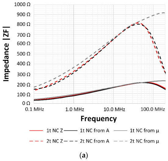
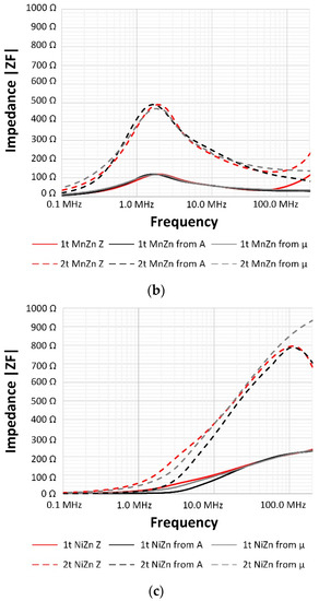
Figure 12.
Comparison of the impedance obtained from three different procedures considering one and two turns wound around the sleeve ferrite core: measuring it directly, mathematically from the relative permeability and extracted from the experimental insertion loss. (a) NC sleeve ferrite core; (b) MnZn sleeve ferrite core; and, (c) NiZn sleeve ferrite core.
Thus, it can be deduced that the measurements obtained with the insertion loss setup can be considered since this method is able to provide accurate measurements with lower influence on the cable used as reference line than the impedance measurement method. Furthermore, with this setup, it is possible to determine the ability of the NC sleeve ferrite core in relation to the widely used MnZn and NiZn cores to suppress electromagnetic noise in cables in the frequency region from 100 KHz to 200 MHz. Therefore, the performance of the three sleeve ferrites characterized in Section 2 can be studied with the aim of determining their ability to filter conducted EMI in terms of decibels instead of the impedance. The theoretical insertion loss parameter is calculated as it has been described in Section 3, this is from the magnitude of the impedance (ZF) of each sleeve ferrite and also, considering the source and load impedances of the system where it is placed. The impedances selected to represent the source and load are defined by the IEC 61000-4-6 standard, taking ZA = ZB = 150 Ω. The sum of these parameters represents a total impedance of 300 Ω; therefore, the sleeve ferrite core must provide a huge value of impedance to obtain an insertion loss higher than three dB. The three sleeve ferrite cores analyzed in this contribution are able to provide values closer to 200 Ω in the case of NC and NiZn and 100 Ω in the case of MnZn (winding one turn). Thus, the results shown in Figure 13 and Figure 14 could be taken as a reference in those systems that present a high load and source impedance. Subsequently, Figure 13 shows the insertion loss parameter measured by means of the experimental setup described, winding one turn around each sleeve ferrite core. As is shown in the impedance data, the novel NC sleeve ferrite core is able to provide a better performance than ceramic cores in most of the analyzed frequency range. It is only surpassed by the MnZn core in the frequency range at which it provides the peak attenuation ratio (0.72–2.62 MHz). The NC core also yields a greater response than NiZn in the low- and medium-frequency region analyzed since it is able to provide a higher attenuation ratio than NiZn up to 78.65 MHz. From this frequency value, the insertion loss provided by the NiZn sleeve ferrite core keeps increasing to reach a value close to 5 dB at 200 MHz, whereas NC begins to lose effectiveness.
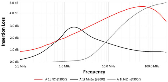
Figure 13.
Comparison of the experimental insertion loss determined for NC, MnZn and NiZn sleeve ferrite cores by winding one turn.
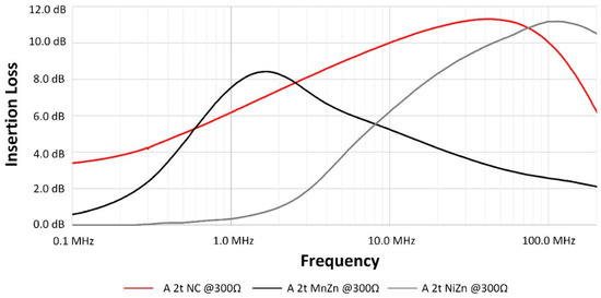
Figure 14.
Comparison of the experimental insertion loss determined for NC, MnZn and NiZn sleeve ferrite cores by winding two turns.
The same comparison is shown in Figure 14, but in this case, the sleeve ferrites are wound with two turns. By winding by two turns, it possible that the NC and NiZn cores are able to provide attenuation rates higher than 10 dB. The predominance of each sleeve ferrite core for the analysis of two turns winding is very similar to the obtained for one turn, since MnZn yields a slightly better response than NC around its resonance frequency, whereas NC improves the MnZn performance below 0.59 MHz and beyond 2.62 MHz. If the novel NC sleeve ferrite core is compared to the NiZn core, the first is able to provide significantly greater performance up to 44.40 MHz. At this frequency value, the resonance is produced in the NC sleeve ferrite core, providing the higher value of attenuation (11.31 dB) and starting to reduce its effectiveness. NC and NiZn traces cross at 76.28 MHz, indicating that beyond this frequency point, NiZn is able to more effectively filter the interferences in the high-frequency region of the whole characterized conducted range. It is important to note that by winding for two turns for the sleeve ferrites, they have improved in a similar way their performance, providing a maximum insertion loss between 2.24-times and 2.90-times greater. Nevertheless, it is possible to observe the drawbacks of this technique in the traces of the NC sleeve ferrite core, since the maximum peaks of attenuation have shifted to about 12.30 MHz. This shift is not shown in the MnZn trace because the resonance observed for this material is due to the ferromagnetic resonance defined by the magnetic features, not for the SFR.
As has been described, the insertion loss provided by a certain sleeve ferrite core is not only dependent on its intrinsic properties but also on the impedance of the line where it is placed. Therefore, it is possible to obtain the insertion loss of the analyzed sleeve ferrite cores through determining their impedance from the insertion loss data measured with the setup described in Section 3. This is carried out by extracting the ZF parameter from Equation (6), by knowing the insertion loss (that has been measured and represented in Figure 13 and Figure 14) and ZA and ZB (the sum of both represents 300 Ω). This ZF can be evaluated together with other impedance values of the system impedance (ZA + ZB) by using Equation (6). Figure 15 shows the performance of the NC sleeve ferrite core compared with the ceramic cores, considering a system impedance of 10 Ω (continuous traces) and 100 Ω (discontinuous traces). This computed insertion loss has been obtained considering the impedance of the three different sleeve ferrite cores after winding only one turn. Note that, the efficiency of the sleeve ferrite cores has doubled in the system with 100 Ω and multiplied by six, reaching the 26.61 dB as a maximum value in the case of NC, when a system with an impedance of 10 Ω is considered.
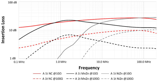
Figure 15.
Extrapolation of the measured insertion loss for systems with an impedance of 100 Ω and 10 Ω, considering one turn for NC, MnZn and NiZn sleeve ferrite cores.
5. Conclusions
Considering the results presented, the suitability of the novel NC sleeve ferrite core prototype in comparison with MnZn and NiZn ceramic cores is validated since it is able to provide a broadband EMI filtering solution in the frequency region studied. Whereas MnZn provides higher attenuation only in the frequencies near to its resonance peak (about 1.8 MHz with a bandwidth of 2.0 MHz), NC yields a great insertion loss throughout the frequency band from 100 KHz to 100 MHz. Regarding the high-frequency region (from 50 MHz), the NiZn sleeve ferrite core provides similar results to the NC solution, achieving a better performance between 78.65 MHz and 76.28 MHz for winding by one and two turns, respectively. In terms of attenuation, the performance of three sleeve ferrites was evaluated through a measurement setup that considers a system with 150 Ω of source and load impedance. The results obtained were compared with those obtained from the measurement of the relative permeability and by directly measuring the impedance and showed good agreement. Thus, the insertion loss measurement setup provides results that can be considered in order to analyze the performance of the NC sleeve ferrite core compared with the ceramic cores.
Therefore, considering all the data presented in this contribution, it is possible to conclude that the novel NC sleeve ferrite core prototype represents an EMI filtering solution to reduce the conducted interferences in the low- and medium-frequency regions (up to 50 MHz). If the EMI disturbance is located specifically in the region covered by MnZn or from 50 MHz, a ceramic core that provides similar performance to that of the NC one may be used. Nonetheless, if the EMI interferences are distributed outside of these regions or from the low-frequency region up to about 100 MHz, the NC sleeve ferrite core shows a better performance than ceramics to reduce EMI emissions in a wideband frequency range.
Author Contributions
Conceptualization, A.S., J.V. and J.T.; Formal analysis, A.S., P.A.M., R.G.-O. and J.S.; Investigation, A.S., J.V., P.A.M., A.A. and J.M.; Methodology, P.A.M., A.A. and J.M.; Project administration, J.T., S.M. and A.G.; Supervision, J.V. and J.T.; Writing—original draft, A.S., J.V. and J.T.; Writing—review & editing, J.V., J.T., P.A.M., A.A., J.M., R.G.-O., J.S., S.M. and A.G.
Funding
The APC was funded by Universitat de València.
Acknowledgments
This work was supported by the Catedra Würth-EMC, a research collaboration agreement between the University of Valencia and Würth Elektronik eiSos GmbH & Co. KG.
Conflicts of Interest
The authors declare no conflict of interest. The founding sponsors had no role in the design of the study; in the collection, analyses, or interpretation of data; in the writing of the manuscript, and in the decision to publish the results.
References
- Valenzuela, R. Novel Applications of Ferrites. Phys. Res. Int. 2012, 2012, 1–9. [Google Scholar] [CrossRef]
- Li, H.; Li, Z.; Zhang, B.; Tang, W.K.; Halang, W.A. Suppressing electromagnetic interference in direct current converters. IEEE Circuits Syst. Mag. 2009, 9, 10–28. [Google Scholar] [CrossRef]
- Underwood, S.J. DC-DC converters suppress EMI: Minimizing EMI at its Source. Power Electron. Technol. 2002, 28, 14–21. [Google Scholar]
- Goldman, A. Modern Ferrite Technology, 2nd ed.; Springer Science & Business Media: Pittsburgh, PA, USA, 2006. [Google Scholar]
- Ott, H.W. Electromagnetic Compatibility Engineering; John Wiley & Sons: Hoboken, NJ, USA, 2009. [Google Scholar]
- Hegarty, T. An Overview of Conducted EMI Specifications for Power Supplies. Available online: http://www.ti.com/lit/wp/slyy136/slyy136.pdf (accessed on 31 May 2019).
- Mainali, K.; Oruganti, R. Conducted EMI Mitigation Techniques for Switch-Mode Power Converters: A Survey. IEEE Trans. Power Electron. 2010, 25, 2344–2356. [Google Scholar] [CrossRef]
- Zhu, H.; Liu, D.; Zhang, X.; Qu, F. Reliability of Boost PFC Converters with Improved EMI Filters. Electronics 2018, 7, 413. [Google Scholar] [CrossRef]
- Zhai, L.; Zhang, T.; Cao, Y.; Yang, S.; Kavuma, S.; Feng, H. Conducted EMI Prediction and Mitigation Strategy Based on Transfer Function for a High-Low Voltage DC-DC Converter in Electric Vehicle. Energies 2018, 11, 1028. [Google Scholar] [CrossRef]
- Urabe, J.; Fujii, K.; Dowaki, Y.; Jito, Y.; Matsumoto, Y.; Sugiura, A. A Method for Measuring the Characteristics of an EMI Suppression Ferrite Core. IEEE Trans. Electromagn. Compat. 2006, 48, 774–780. [Google Scholar] [CrossRef]
- Hartmann, M.; Ertl, H.; Kolar, J.W. EMI Filter Design for a 1 MHz, 10 kW Three-Phase/Level PWM Rectifier. IEEE Trans. Power Electron. 2011, 26, 1192–1204. [Google Scholar] [CrossRef]
- Lukovic, M.D.; Nikolic, M.V.; Blaz, N.V.; Zivanov, L.D.; Aleksic, O.S.; Lukic, L.S. Mn-Zn Ferrite Round Cable EMI Suppressor with Deep Grooves and a Secondary Short Circuit for Different Frequency Ranges. IEEE Trans. Magn. 2013, 49, 1172–1177. [Google Scholar] [CrossRef]
- Cuellar, C.; Tan, W.; Margueron, X.; Benabou, A.; Idir, N. Measurement method of the complex magnetic permeability of ferrites in high frequency. In Proceedings of the Instrumentation and Measurement Technology Conference (I2MTC), Graz, Austria, 13–16 May 2012; pp. 63–68. [Google Scholar]
- University of York. Link PCP—EMC Aspects of Mobile Telecommunications Systems, Appendix G—Coupling of EMI to Cables: Theory and Models (Final Report). Available online: https://pdfs.semanticscholar.org/cd27/bdd7dab556ce1d0c8e1da41cf9a5605f3d4f.pdf (accessed on 30 November 2018).
- Urabe, J.; Fujii, K.; Harun, A.M.B.; Matsumoto, Y.; Sugiura, A. A study of EMI suppression characteristics of ferrite cores. In Proceedings of the 17th International Zurich Symposium on Electromagnetic Compatibility (EMC), Zurich, Switzerland, 27 February–3 March 2006; pp. 622–625. [Google Scholar]
- Damnjanovi, M.; Stojanovi, G.; Živanov, L.; Desnica, V. Comparison of different structures of ferrite EMI suppressors. Microelectron. Int. 2006, 23, 42–48. [Google Scholar] [CrossRef]
- Stojanović, G.; Lečić, N.; Damnjanović, M.; Živanov, L. Electrical and temperature characterization of NiZn ferrites. Int. J. Appl. Electromagn. Mech. 2011, 35, 165–176. [Google Scholar] [CrossRef]
- Saotome, H.; Sakaki, Y. Complex permeability of polycrystalline Mn-Zn and Ni-Zn ferrites. Electr. Eng. Jpn. 1998, 123, 1–7. [Google Scholar] [CrossRef]
- Suarez, A.; Victoria, J.; Alcarria, A.; Torres, J.; Martinez, P.A.; Martos, J.; Soret, J.; Garcia-Olcina, R.; Muetsch, S. Characterization of Different Cable Ferrite Materials to Reduce the Electromagnetic Noise in the 2–150 kHz Frequency Range. Materials 2018, 11, 174. [Google Scholar] [CrossRef] [PubMed]
- Herzer, G.; Vazquez, M.; Knobel, M.; Zhukov, A.; Reininger, T.; Davies, H.A.; Sanchez Ll, J.S. Round table discussion: Present and future applications of nanocrystalline magnetic materials. J. Magn. Magn. Mater. 2005, 294, 252–266. [Google Scholar] [CrossRef]
- Thierry, W.; Thierry, S.; Benoît, V.; Dominique, G. Strong volume reduction of common mode choke for RFI filters with the help of nanocrystalline cores design and experiments. J. Magn. Magn. Mater. 2006, 304, 847–849. [Google Scholar] [CrossRef]
- Herzer, G. Modern soft magnets: Amorphous and nanocrystalline materials. Acta Mater. 2013, 61, 718–734. [Google Scholar] [CrossRef]
- Liu, Y.; Han, Y.; Liu, S.; Lin, F. Pulse Magnetic Properties Measurement and Characterization of Fe-Based Nanocrystalline Cores for High-Voltage Pulse Magnetics Applications. IEEE Trans. Power Electron. 2015, 30, 6883–6896. [Google Scholar] [CrossRef]
- Naishadham, K. Closed-Form Design Formulas for the Equivalent Circuit Characterization of Ferrite Inductors. IEEE Trans. Electromagn. Compat. 2011, 53, 923–932. [Google Scholar] [CrossRef]
- Weinschrott, A.; Weinschrott, A. New measurement method for high frequency cable mounted ferrites. In Proceedings of the 2005 International Symposium on Electromagnetic Compatibility, Chicago, IL, USA, 8–12 August 2005; pp. 312–314. [Google Scholar]
- Schulze, S.; Al-Hamid, M.; Leone, M. Detailed study of different cable ferrite characterization methods using simulation and measurement. In Proceedings of the 2017 International Symposium on Electromagnetic Compatibility-EMC Europe, Angers, France, 4–7 September 2017; pp. 1–5. [Google Scholar]
- Brander, T.; Gerfer, A.; Rall, B.; Zenkner, H. Trilogy of Magnetics: Design Guide for EMI Filter Design, SMP & RF Circuits, 4th ed.; Swiridoff Verlag: Künzelsau, Germany, 2010. [Google Scholar]
- Saito, T.; Takemoto, S.; Iriyama, T. Resistivity and core size dependencies of eddy current loss for Fe-Si compressed cores. IEEE Trans. Magn. 2005, 41, 3301–3303. [Google Scholar] [CrossRef]
- Moongilan, D. Termination effects on attenuation properties of ferrites installed around cable conductors. In Proceedings of the 2013 International Symposium on Electromagnetic Compatibility, Denver, CO, USA, 5–9 August 2013; pp. 107–112. [Google Scholar]
- Suarez, A.; Victoria, J.; Alcarria, A.; Torres, J. Characterization of electromagnetic noise suppression sheet for aerospace applications. In Proceedings of the ESA Workshop on Aerospace EMC, Valencia, Spain, 23–25 May 2016; pp. 1–6. [Google Scholar]
- Victoria, J.; Suarez, A.; Torres, J.; Martinez, P.A.; Alcarria, A.; Martos, J.; Garcia-Olcina, R.; Soret, J.; Muetsch, S.; Gerfer, A. Transmission Attenuation Power Ratio Analysis of Flexible Electromagnetic Absorber Sheets Combined with a Metal Layer. Materials 2018, 11, 1612. [Google Scholar] [CrossRef]
- Hu, P.; Yang, H.B.; Pan, D.A.; Wang, H.; Tian, J.J.; Zhang, S.; Wang, X.; Volinsky, A.A. Heat treatment effects on microstructure and magnetic properties of Mn-Zn ferrite powders. J. Magn. Magn. Mater. 2010, 322, 173–177. [Google Scholar] [CrossRef]
- Beatrice, C.; Bottauscio, O.; Chiampi, M.; Fiorillo, F.; Manzin, A. Magnetic loss analysis in Mn-Zn ferrite cores. J. Magn. Magn. Mater. 2006, 304, e743–e745. [Google Scholar] [CrossRef]
- Sun, G.L.; Li, J.B.; Sun, J.J.; Yang, X.Z. The influences of Zn2+ and some rare-earth ions on the magnetic properties of nickel-zinc ferrites. J. Magn. Magn. Mater. 2004, 281, 173–177. [Google Scholar] [CrossRef]
- Costa, A.C.F.M.; Tortella, E.; Morelli, M.R.; Kiminami, R.H.G.A. Synthesis, microstructure and magnetic properties of Ni-Zn ferrites. J. Magn. Magn. Mater. 2003, 256, 174–182. [Google Scholar] [CrossRef]
- Snelling, E.C. Soft Ferrites, Properties and Applications, 2nd ed.; Butterworth: Boston, MA, USA, 1988. [Google Scholar]
- Reeve, W.D.; Hagen, T. Applying and Measuring Ferrite Beads: Part I Ferrite Bead Properties and Test Fixtures. Available online: http://www.reeve.com/Documents/Articles%20Papers/Ferrite%20Beads/Reeve-Hagen_FerriteBeads_P1.pdf (accessed on 30 November 2018).
- Paul, C.R. Introduction to Electromagnetic Compatibility, 2nd ed.; Wiley Interscience: Hoboken, NJ, USA, 2006. [Google Scholar]
- Ott, H.W. Noise Reduction Techniques in Electronic Systems; John Wiley & Sons: Hoboken, NJ, USA, 1988. [Google Scholar]
- Keysight E5061B-3L3/3L4/3L5 LF-RF Network Analyzer with Option 005 Impedance Analysis Function. Available online: http://literature.cdn.keysight.com/litweb/pdf/5990-7033EN.pdf (accessed on 30 November 2018).


© 2019 by the authors. Licensee MDPI, Basel, Switzerland. This article is an open access article distributed under the terms and conditions of the Creative Commons Attribution (CC BY) license (http://creativecommons.org/licenses/by/4.0/).