1. Introduction
Worldwide, around 466 million people are suffering from debilitating hearing loss [
1]. Amongst other things, hearing loss lowers the quality of life of the people it affects [
2]. Digital Hearing Aids (HA) are the most common auxiliary listening devices used by people with hearing loss [
3]. HA technology has developed over recent years, but only one-third of patients with ear problems use HA devices. This is an extremely small proportion when considering the total number of people suffering from hearing loss [
4]. There are many reasons for the low levels of HA usage, which include background noise and poor sound quality or feedback; however, the main reason given is that of poor user experience [
5,
6].
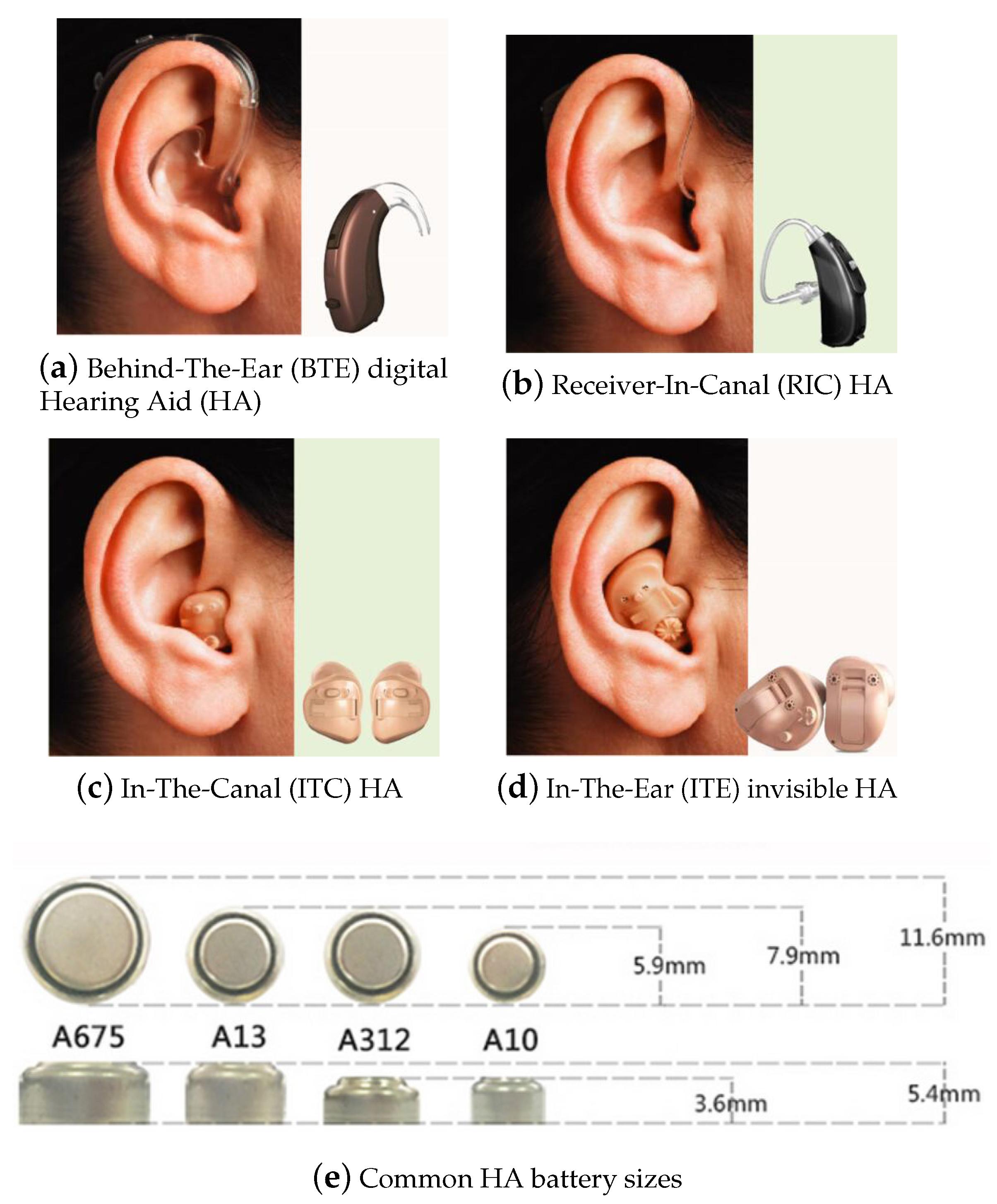
Hearing aids vary greatly in size and in the way in which they are placed in the ears. There are four common HA, as shown in
Figure 1.
Figure 1a shows a Behind-The-Ear (BTE) HA, which is the largest type of HA.
Figure 1b shows a Receiver-In-Canal (RIC) HA, which is less visible than the BTE type.
Figure 1c shows an In-The-Canal (ITC) HA. ITC HA are relatively large compared to the ears.
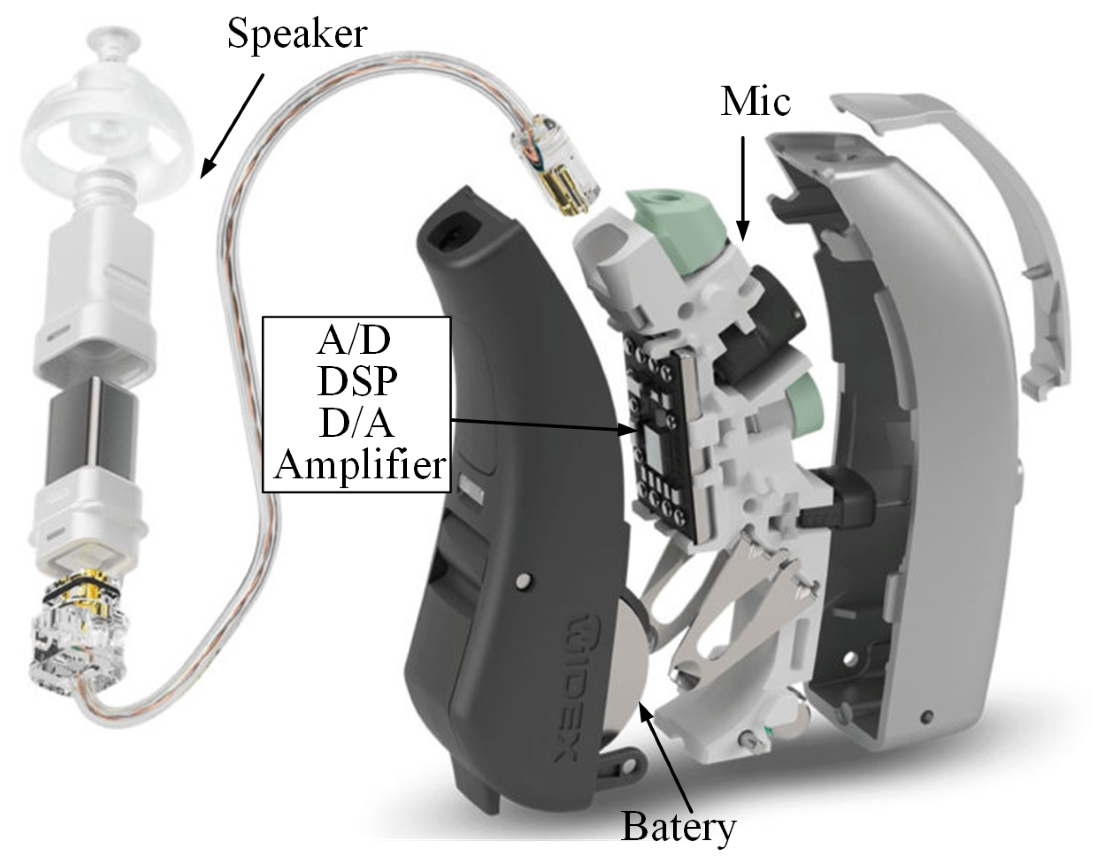
Figure 1d shows an In-The-Ear (ITE) HA, which is customized and less visible. All types of HA adopt the same structure to collect and regenerate sounds. A basic digital HA is shown in
Figure 2 [
7]. The basic digital HA structure is composed of a microphone, an Analog-to-Digital converter (A/D), an amplifier, a Digital Signal Processor (DSP), a Digital-to-Analog converter (D/A), a speaker, and a battery. The existing HA structure adopts a built-in DSP for voice processing.
HA manufacturers are making hearing aids smaller and smaller in order to meet the increasing requirements of the hearing aid being invisible. Correspondingly, both the battery space (shown in
Figure 1e) and capacity have been reduced. Thus, smaller HA may not meet the expected demands of improved listening [
8].
Table 1 shows the battery capacity of HA on the market [
9]. The battery capacity is becoming smaller and smaller. As a result, HA manufacturers have had to balance power consumption and user experience.
About 89% of hearing impaired people are suffering from binaural hearing loss [
10,
11] and so need to use two HA at the same time [
12]. The two-HA systems (in which the left HA and the right HA work independently of each other) cannot deliver the positioning information of the original acoustic cues, thus distorting the listener’s sense of auditory space and making it hard for listeners to locate sounds and track sound sources [
13]. In terms of noise reduction, the two HA systems can reduce noise to some extent, but binaural HA, which differ from the two HA systems in that they do not work independently, are highly recommended by doctors [
14]. The noise reduction of binaural HA has been proven to be more effective than two HA systems, which process noise independently, because the former can use more spatial information [
15]. However, the binaural interconnection is the biggest challenge impeding the development of binaural HA [
16,
17,
18,
19,
20]. In spite of the advances in HA technology, balancing the algorithms and user experience remains a challenge, mainly due to the limitations of current HA structures. Some solutions have been proposed by research teams to overcome these problems [
21,
22,
23,
24]. An Android-based smartphone and HA can be connected via Bluetooth, which then controls the volume and parameters of the HA through a graphical user interface [
21]. This method improves the ease of use of the HA, but fails to improve the speech intelligibility. The latest commercial HA connects directly to IOS, Android, or other Bluetooth-enabled phones by Bluetooth to listen to music, audio books, and podcasts. Bluetooth technology as an auxiliary means can improve the utilization of HA, but cannot solve the problems mentioned above [
22]. In [
23,
24], the team developed an auxiliary HA device using smartphones and wireless technologies. The speaker’s voice, which is captured by the microphone of the smartphone close to the speaker, is transmitted to the HA via Bluetooth. Since the collected sound is directional, the speech intelligibility can be improved in specific environments. The above-mentioned methods have more or less enhanced the ease of use of HA; however, the previously-mentioned problems related to the structural limitations of HA still need to be solved.
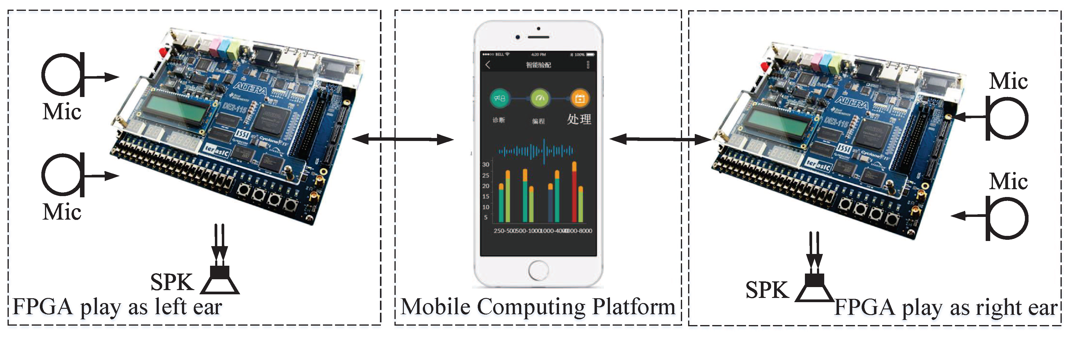
Against this background, a smart binaural hearing aid based on a Mobile Computing Platform (MCP) is proposed to solve these problems. In this study, an MCP is chosen as an auxiliary device to run the real-time algorithm application. A 400-MHz Transceiver/Receiver (TRX) is used to connect the MCP with the HA. The key contributions of this structure are as follows:
- (1)
User-friendly: Only an HA and an MCP are required for the connection.
- (2)
Better intelligibility: Binaural algorithms are used without being limited by complexity.
- (3)
More power supply: A DSP is not used in the HA. The freed space gives the option of increasing battery capacity or reducing the size of the earpieces.
- (4)
Convenient algorithm update procedure: The algorithm and system can be updated more conveniently through an MCP wireless connection as compared with traditional built-in DSP HA.
The outline of this paper is as follows:
Section 2 describes the structure of the proposed HA.
Section 3 describes the circuit blocks.
Section 4 presents the hardware implementation. An evaluation of the methods and experimental results is presented in
Section 5. Finally, a conclusion is drawn in
Section 6.
2. The Proposed Architecture of HA
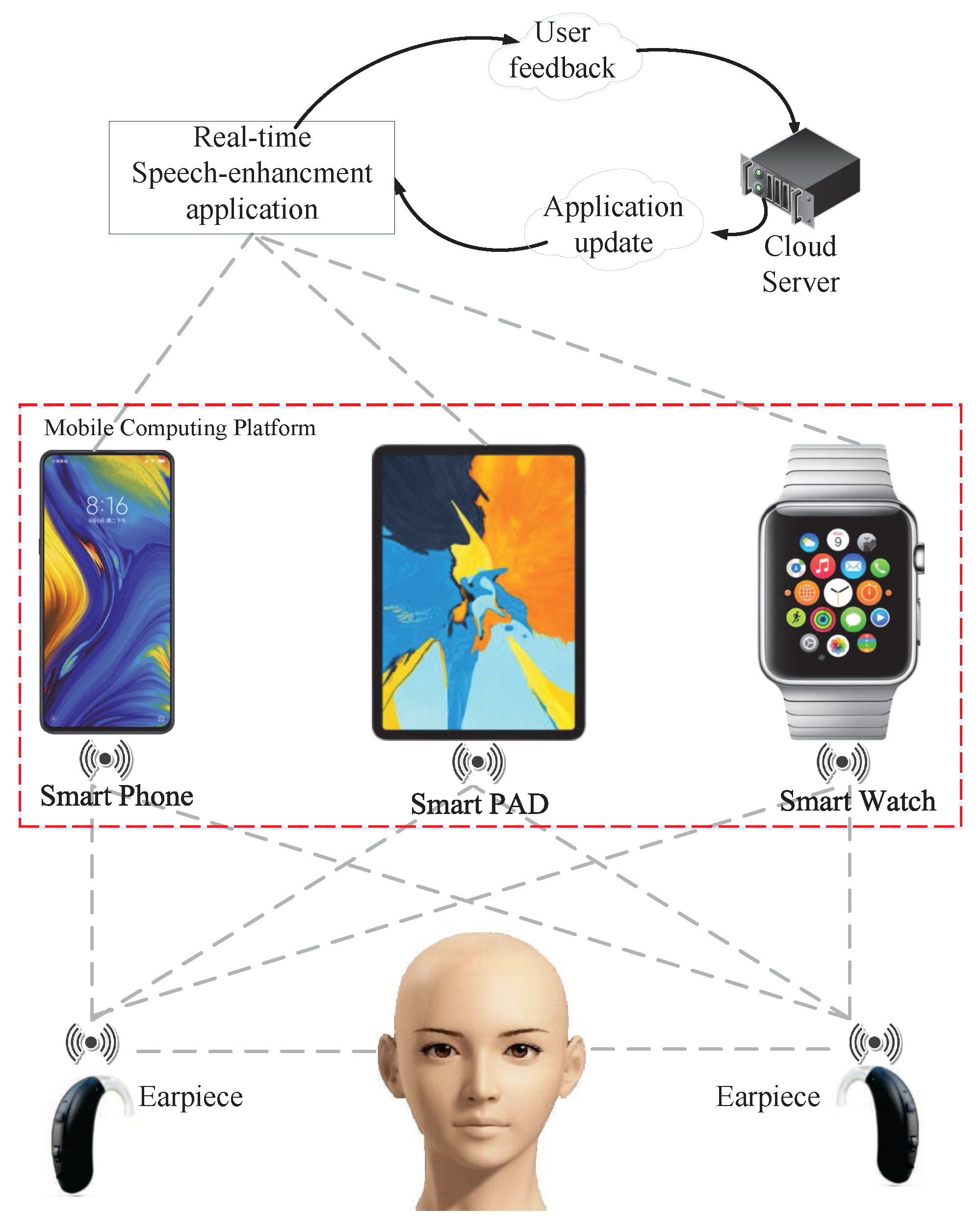
The structure of the proposed binaural HA device is shown in
Figure 3. There are three main parts: the earpieces, the MCP, and the real-time speech-enhancement application. There is a cloud server that can update software and receive user feedback. Customized algorithms can improve the user experience according to the user feedback. The earpieces are placed on the ears of people with hearing loss to collect sound from the environment and return the sound to the people. The MCP (such as a smartphone, smart watch, or smart PAD), pre-paired with the earpieces, receives information from the earpieces and then transmits the information to the real-time speech-enhancement application. A real-time speech-enhancement application, which is running on the MCP, reduces noise, manages the positioning, thus improving user experience, and then transmits the sound back to the earpieces. The earpieces contain a microphone, speaker, Digital Acoustic Baseband (DABB) processor, and a 400-MHz Radio Frequency (RF) transceiver. The MCP has the same DABB and RF transceiver as the earpiece. The earpiece can collect, playback, and transmit sound. The MCP processes the received voice signal and transfers it back with the transceiver. The MCP provides sufficient power and powerful computing processors to run the speech-enhancement application. The advanced binaural speech-enhancement applications running on the MCP can reduce noise and improve the user experience.
The sound is captured by the microphones in the earpieces, which can also generate sound and return signals. Each earpiece has two omnidirectional microphones, which provide accurate data to facilitate noise reduction and positioning.
Earpieces can be connected with the MCP through the 400-MHz wireless link; the left and the right earpieces are also linked. Compared with higher Hz such as 2.4 GHz and 5 GHz, the 400-MHz wireless link achieves lower power consumption and path loss.
The real-time software implements the binaural DSP algorithms through the MCP. As a result of the enhanced computing and storage capacities, the algorithm can achieve better performance and more functions than the traditional algorithms in HA.
This new structure is adopted with the ultimate aim of providing an auxiliary device, which enhances the processing performance. The auxiliary device includes, but is not limited to smart phones, smart PADs, and smart watches. These can be used as an MCP as long as they are based on Android or IOS, are easy to carry around, and have a strong processor with sufficient power. This structure provides a trade-off between power consumption and user experience.
3. Circuit Blocks
3.1. Wireless Transceiver
For the compressed 32-kbps audio stream, if the full-duplex transceiver is used, the transceiver module has to work continuously, which is not optimal for reducing the power consumption or reducing the complexity of the system design. In this design, intermittent information exchange is utilized with a much higher bit rate. Thus, the transceiver module is duty cycled to reduce the average power consumption. For RF circuits, increasing the bit rate would not significantly increase the power consumption and would help shorten the communication latency. A 2-Mbps communication bit rate is used to reduce the average power consumption by more than 80%.
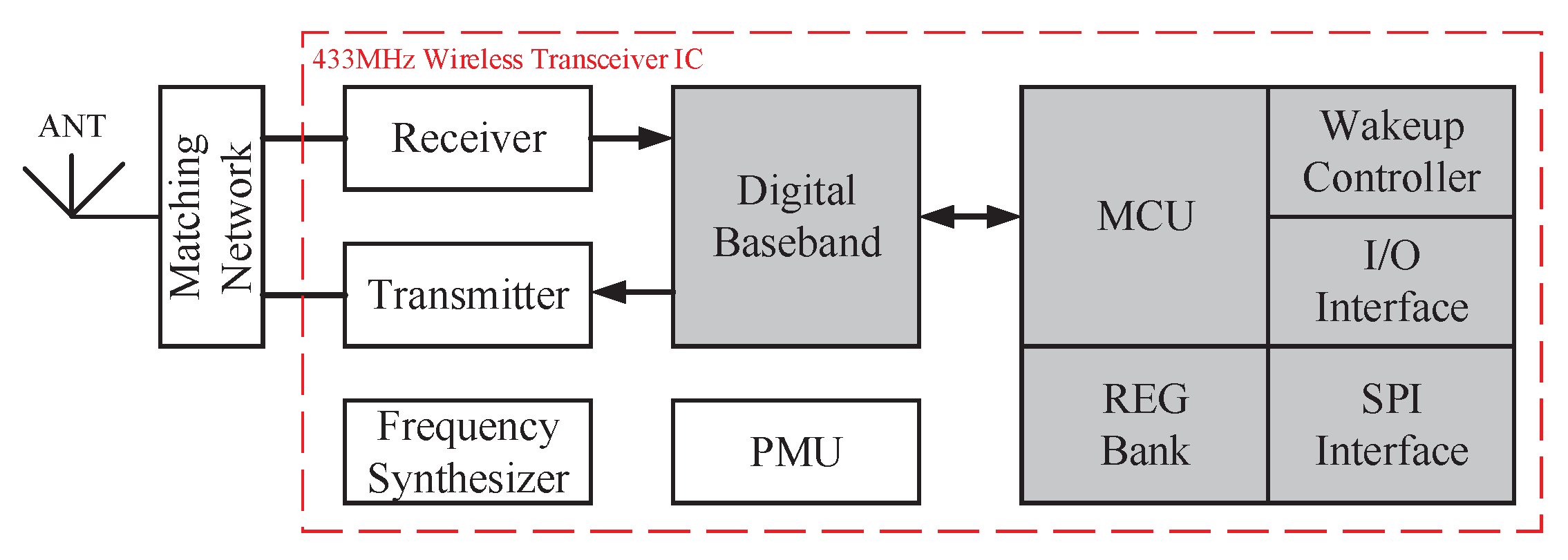
As is shown in
Figure 4, The transceiver uses a carrier frequency of 434 MHz near the Industrial Scientific Medical (ISM) band. A higher carrier frequency such as 2.4 GHz or 5 GHz leads to higher power consumption and higher path loss around the human body, while a lower frequency is challenging because of the need for a miniaturized antenna.
The transmitter uses a polarized structure. Compared to the traditional orthogonal modulation of the transmitter, a polarized transmitter can effectively reduce the circuit complexity, eliminating the building blocks required in the traditional structure, such as the DAC, IFfilter, and mixer. The transmitter power consumption can be reduced accordingly. The receiver employs a zero-IF structure, which simplifies the receiver’s IF circuit and digital baseband; however, the main drawback is the degradation of the dynamic range due to the DC offset. In this design, a novel DC offset calibration method is utilized, which can eliminate the DC offset with barely any extra power consumption.
In addition to the employed power-efficient transceiver architecture, some low-power building-block techniques are also adopted. In the intermittent information exchange mode, each communication cycle is roughly composed of an operation state and an idle state. Thus, two effective methods for reducing the average power consumption involve shortening the duration of the operation state in each communication cycle and lowering the idle state power consumption.
When the communication bit rate (2 Mbps) is much higher than the audio stream bit rate (32 kbps), the duty cycle of the operation state is relatively low. On the other hand, the period of intermittent information exchange should not be longer than several milliseconds to keep the communication latency within an acceptable threshold. In this condition, the duration of the operation state in each cycle is tens of microseconds, which is comparable with the communication setup time between two transceivers. Therefore, in this design, the communication setup time is especially optimized to shorten the operation state duration in each cycle, using the two corresponding techniques. The first one is utilized to shorten the Phase Lock Loop (PLL) setup time. Since the PLL setup time is decided by its loop bandwidth and has a trade-off with its phase noise, a dynamic loop bandwidth technique is adopted, which helps to reduce the setup time by one order of magnitude while having almost no affect on noise performance. Another technique is utilized to shorten the Auto Gain Control (AGC) loop setup time. Since the zero-IF receiver architecture is employed, the signal magnitude detection speed at the IF circuit output is limited by its bit rate. Here, we utilize the combination of RF-AGC and IF-AGC. The RF-AGC has a fast speed and provides a coarse gain range for IF-AGC. Then, the IF-AGC sets the gain accurately. This technique shortens the setup time significantly compared with conventional AGC circuits while still having a comparable precision.
When the transceiver works in the idle state, all the power-consuming circuits are powered off except for an ultra-low-power wake-up controller. The wake-up controller includes a low-frequency oscillator, a simple state machine, and several counters. It powers the transceiver on and off periodically according to a schedule. Because of its simplicity and low frequency, it consumes less than 50 μW, which contributes very little to the average power consumption of the whole system. The TRX in the verification system was published in [
26].
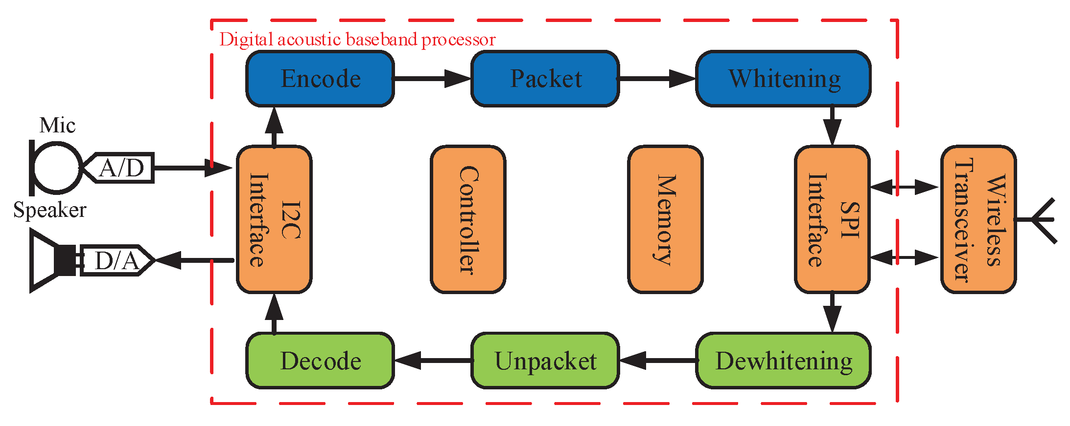
3.2. Digital Acoustic Baseband Processor
The DABB processor is an integrated control and interface unit coordinating the functions of the surrounding modules including the ADC, DAC, and the wireless transceiver, which are shown in
Figure 5.
The DABB interfaces the wireless transceiver with a four-wire Serial Peripheral Interface (SPI). The instruction structure of the SPI allows reading and writing of the register unit of the radio transceiver to set the status, to monitor whether there is an error in the transmission, to send interruptions, and to adjust the working mode.
In the SPI communication, the wireless transceiver functions as the slave, and the DABB as the master. The SPI protocol is for an 8-bit packet transmission. Each packet includes a prefix and a number of data packets. The prefix contains the access type and the register address, followed by several read and write packets.
The DABB controls the working modes of the ADC and DAC through the I2C bus. The data from the ADC is retrieved by the optionally selectable I2C bus or the SPI interface to the processor.
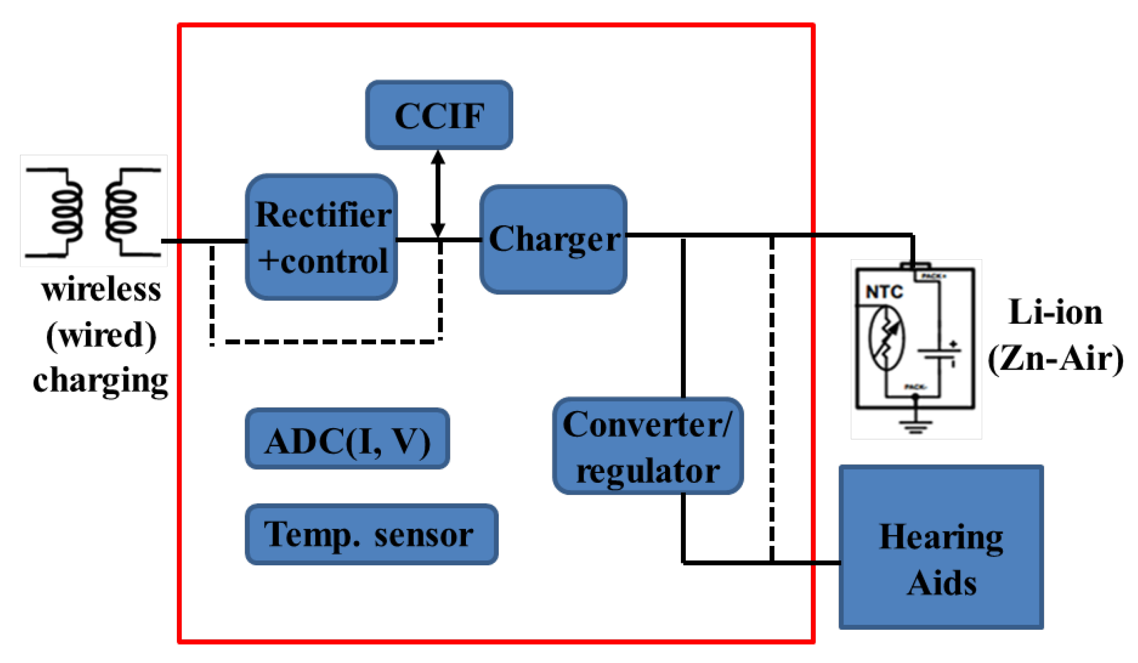
3.3. Battery and Power Management
The Battery/Power Management Unit (BPMU) in the proposed system mainly acts as the friendly charger for the built-in rechargeable batteries and the voltage generator for the hearing aid devices. In this case, the users do not need to change the batteries frequently. The diagram of the BPMU is illustrated in
Figure 6.
The BPMU is supplied by two methods. When the wireless charging system is adopted, the transferred AC voltage from the outside coils is firstly rectified by an internal high-performance rectifier before being sent to the charger.
In order to enhance the power efficiency, control techniques are used in the rectifier design. When only wired charging is available, the input voltage of the internal charger is directly supported from the outside cable. The supported rechargeable battery type is the widely-used lithium-ion (Li-ion). The BPMU can also detect the popular disposable zinc-air (Zn-air) battery, but does not charge it. Charging algorithms are proposed in the BPMU to control the charging processes for high efficiency and battery protection. In addition, the BPMU includes a Charger Communication Interface (CCIF) to provide the battery charging information for the user with the BPMU.
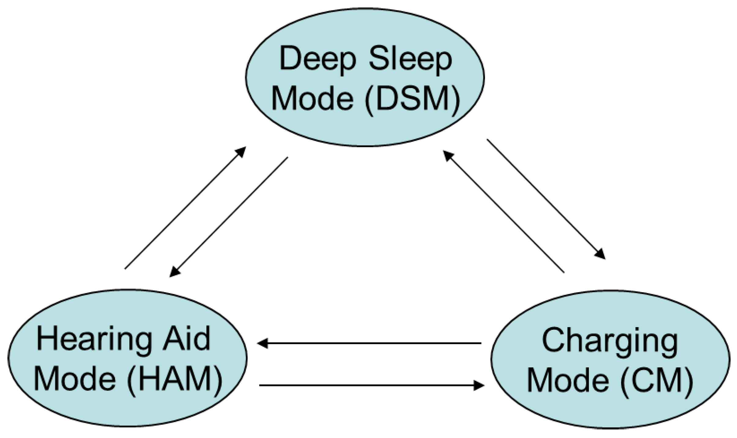
There are three working modes in the BPMU as illustrated in
Figure 7. They are Deep Sleep Mode (DSM), Hearing Aid Mode (HAM), and Charging Mode (CM). The three modes transit with each other for practical working situations. When the BPMU is in DSM, all the blocks are turned off to save power, and the system current is no more than 200 nA.
When the BPMU enters into HAM, the hearing aids are in the normal operation condition and receive their supply voltage from the BPMU. If a Li-ion battery is used, an internal high-efficiency converter or regulator is activated to provide an output voltage between 1.0 V and 1.4 V to the hearing aids. If a Zn-air battery, whose normal voltage is between 1.1 V and 1.5 V, is used, the BPMU can also directly provide the battery voltage to the hearing aids. In HAM, voltage monitoring is also used to prevent turn-on if the battery voltage is not suitable. According to the Li-ion discharge curve, the battery is nearly discharged when the battery voltage is less than 3 V, and so, a threshold of around 3 V is chosen as a turn-off threshold when the Li-ion battery is used.
When the BPMU works in CM, the battery is being charged. Note that the hearing aids will turn off while charging. For Li-ion batteries, the charging process is managed by a state machine containing start-up, initialization or a so-called trickle pre-charge, constant-current charging, constant-voltage charging, and completion. The maximum charging current is around 21 mA. With the aim of protecting the battery and maximizing the battery life, the precise charging control loop involves monitoring both the current and voltage with the help of the internal ADCs and temperature sensor. The CCIF will communicate the status of the charging process in CM to allow user interaction. The communicated information includes the charging process, the voltage and current levels, the temperature, and failure conditions. When wireless charging is used, this communication supports bidirectional data transfer between the BPMU and the outside transmitter. The communication from the BPMU to the transmitter is based on load modulation, and the communication from the transmitter to the BPMU uses voltage modulation. If a Zn-air battery is used, the battery type is detected in the start-up state, and the state machine moves directly to the completion phase.
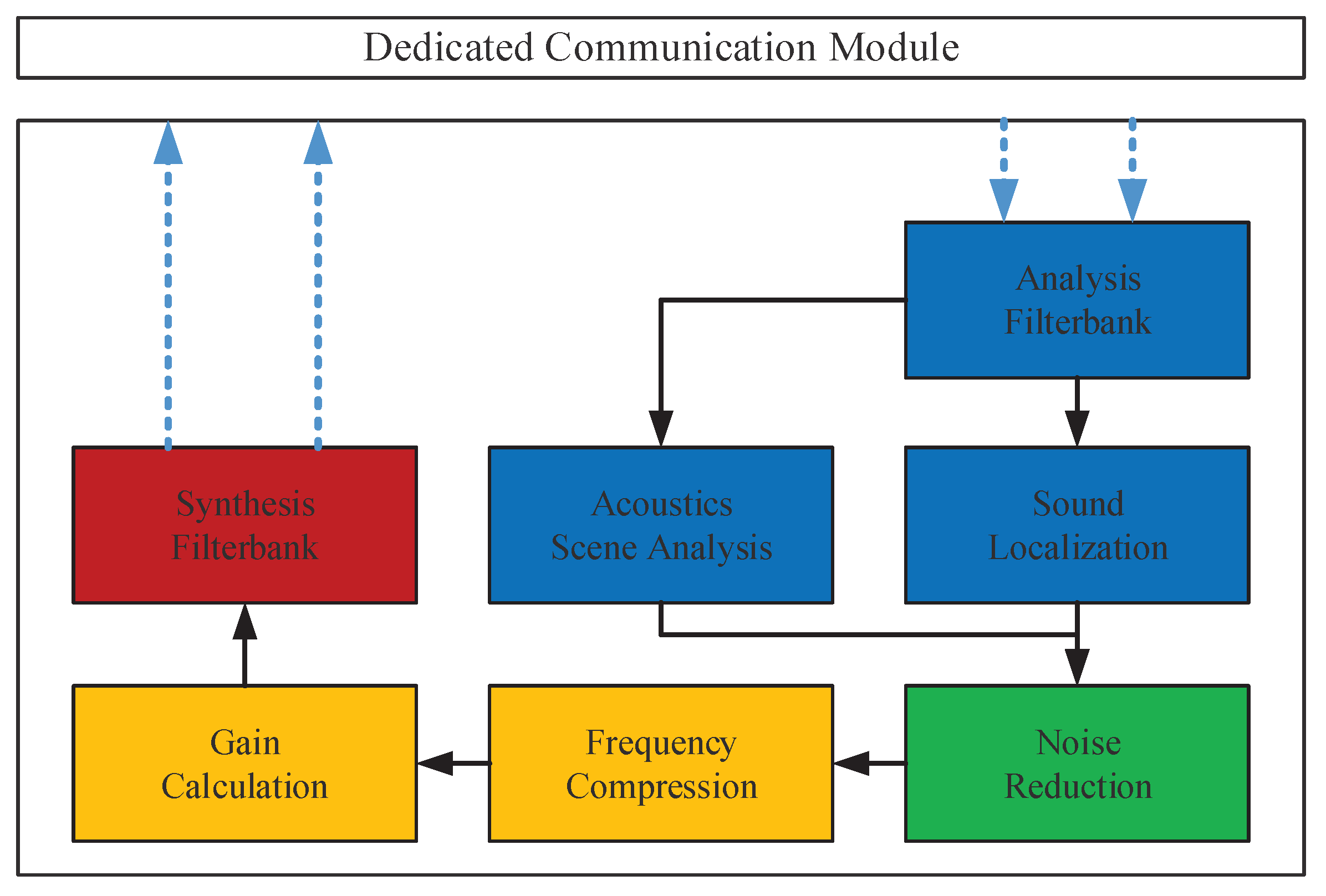
3.4. Real-Time Software
The real-time software implements the binaural DSP algorithms through the smartphone’s powerful computing platform. As a result of the increasing computing abilities and storage capacities of smartphones, the algorithms can achieve a better performance and implement more functions than traditional processing platforms located in the ear devices.
As shown in
Figure 8, the real-time software picks up four audio streams from the front and rear microphones located in the right ear and left ear. The binaural signal is subjected to the filter bank analysis and divided into different channels based on human auditory characteristics. After pre-processing, the acoustic features are extracted and used to match different acoustic scenes for further processing.
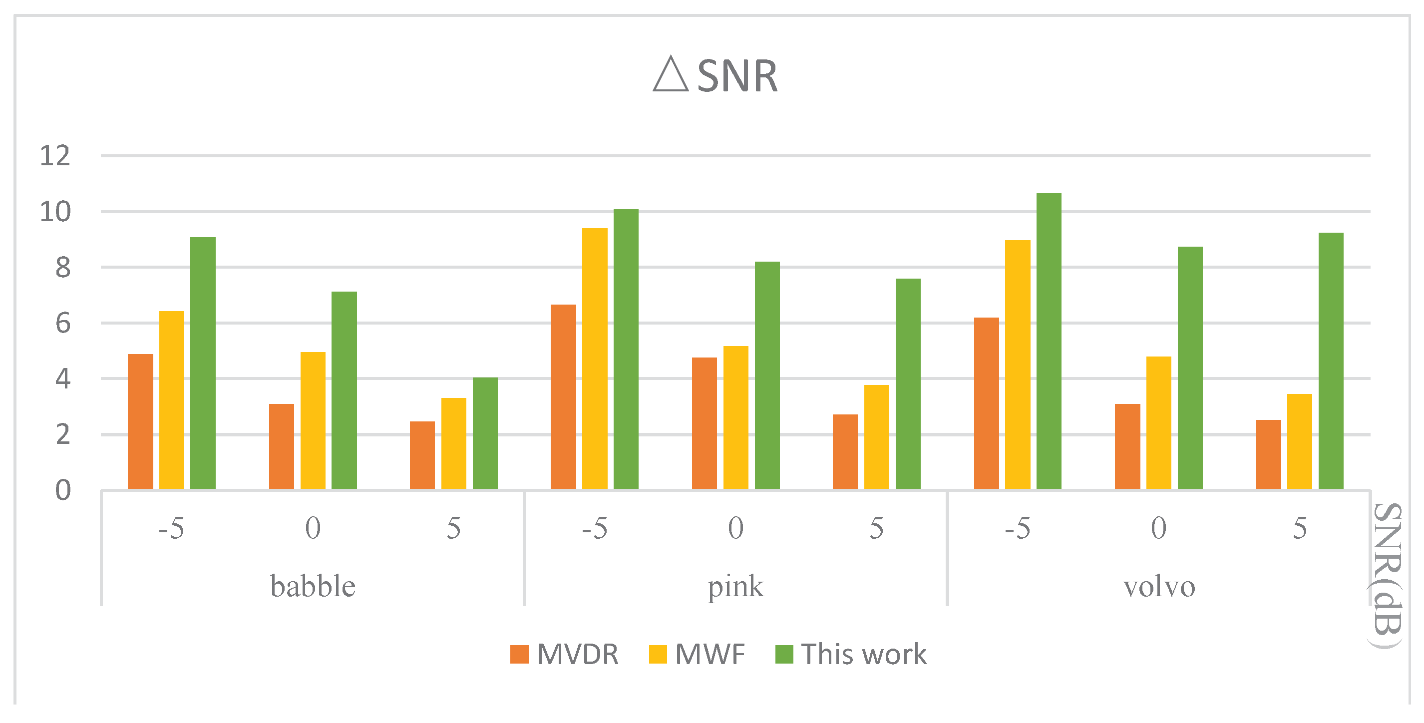
Adaptive speech-enhancement algorithms for different acoustic environments are applied to improve the subjective experience of hearing. Sound features like binaural cues (such as interaural level and time differences) can be used to determine the localization of the sound source. After locating the target sound source, the noise-reduction algorithms are applied, and the Signal-to-Noise Ratio (SNR) can be increased to improve the speech intelligibility. Considering the users’ experience of HA, the cancellation of the echo suppression feedback is important for preventing whistling and gaining sufficient sound compensation.
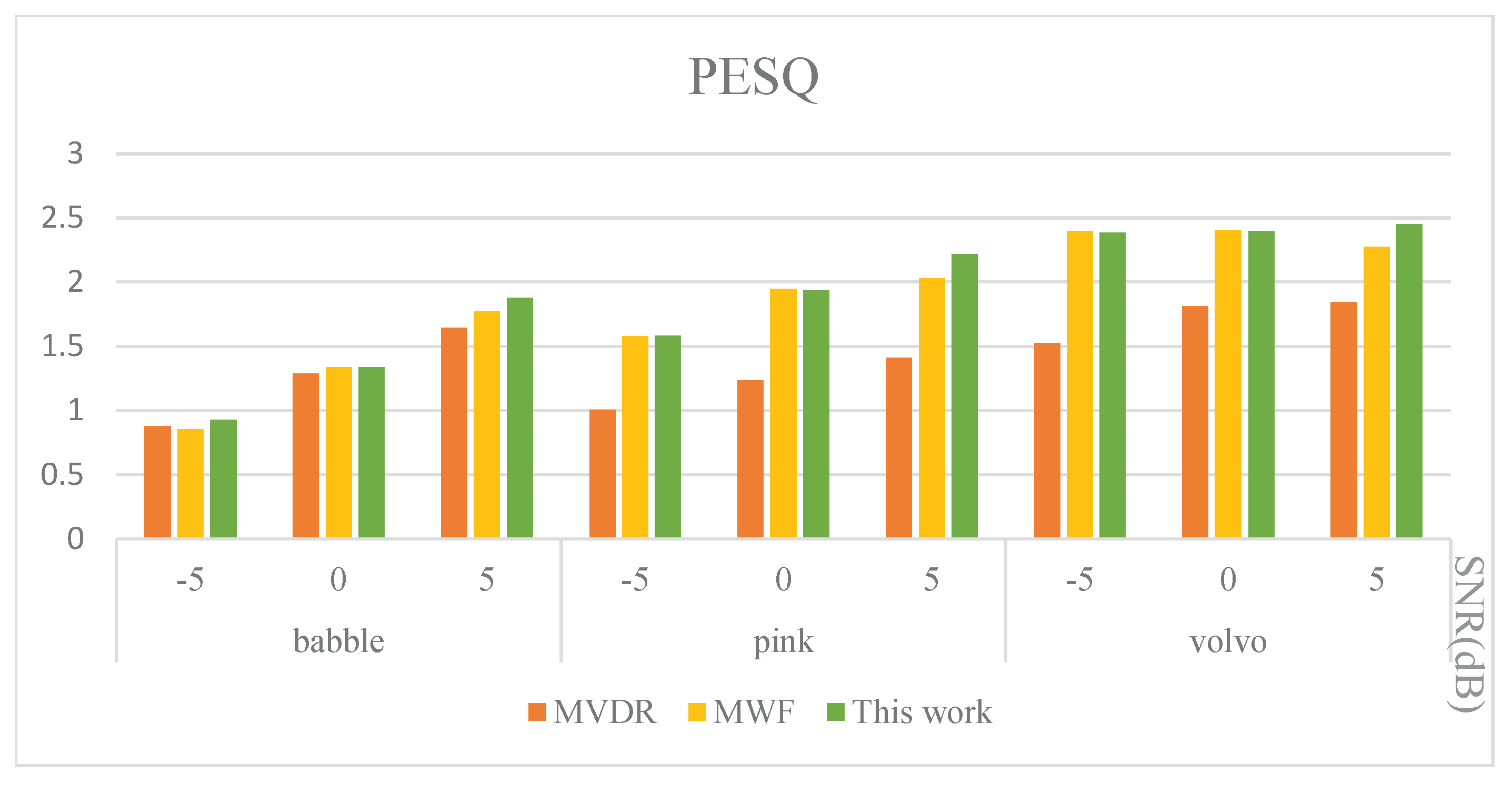
After achieving a relatively clean sound signal, acoustic compensation is used to restore the hearing abilities for patients with hearing loss. On the basis of the results of patients’ audiometry, gain calibration and frequency compression can be precisely calculated and compensated in each frequency band. The processed signal outputs to the stereo signal after passing through the synthesis filter banks back to the right and left ear. The algorithm used in the verification system was published in [
27].
4. Hardware Implementation
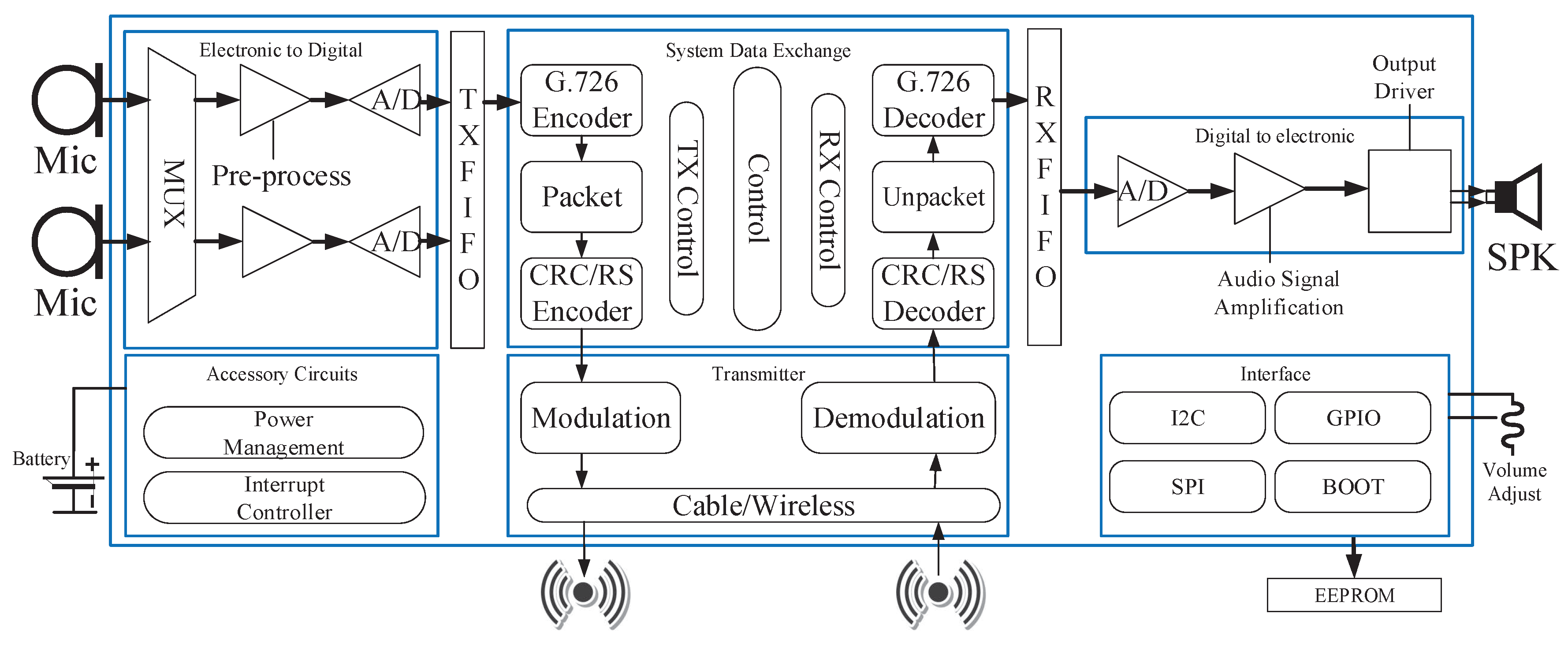
The block diagram of the earpieces is shown in
Figure 9. It mainly includes the following modules: electronic to digital, system data exchange, digital to electronic, accessory circuits, transmitter, interface, First In, First Out (FIFO) buffer, FIFO for processing input, output, and intermediate data. Accessory circuits include power management and the interrupt controller. The transmitter is used mainly for cable/wireless transmission. The interface supports various types of external communications. In the following subsections, we introduce the remaining modules separately.
4.1. The Electronic to Digital
The electronic to digital signal module comprises a pre-process and the 16-bit, 2-MHz A/D. The pre-process amplifies and adjusts the signal from the microphones to meet the requirements of the A/D, which converts the analog data to digital data and then outputs them for further processing.
4.2. The Signal Data Exchange
The system data exchange module controls data flow. Firstly, the frame structure is introduced. Then, the circuit design of the data exchange module implementation is presented. Finally, the optimized operating scheme for reducing power consumption is discussed. There are two separate controllers: one is for the transmitter, which sends a control signal to start the transmission process, while the other is for the receiver, which receives “to_do” signals if it detects a packet in the receiver FIFO.
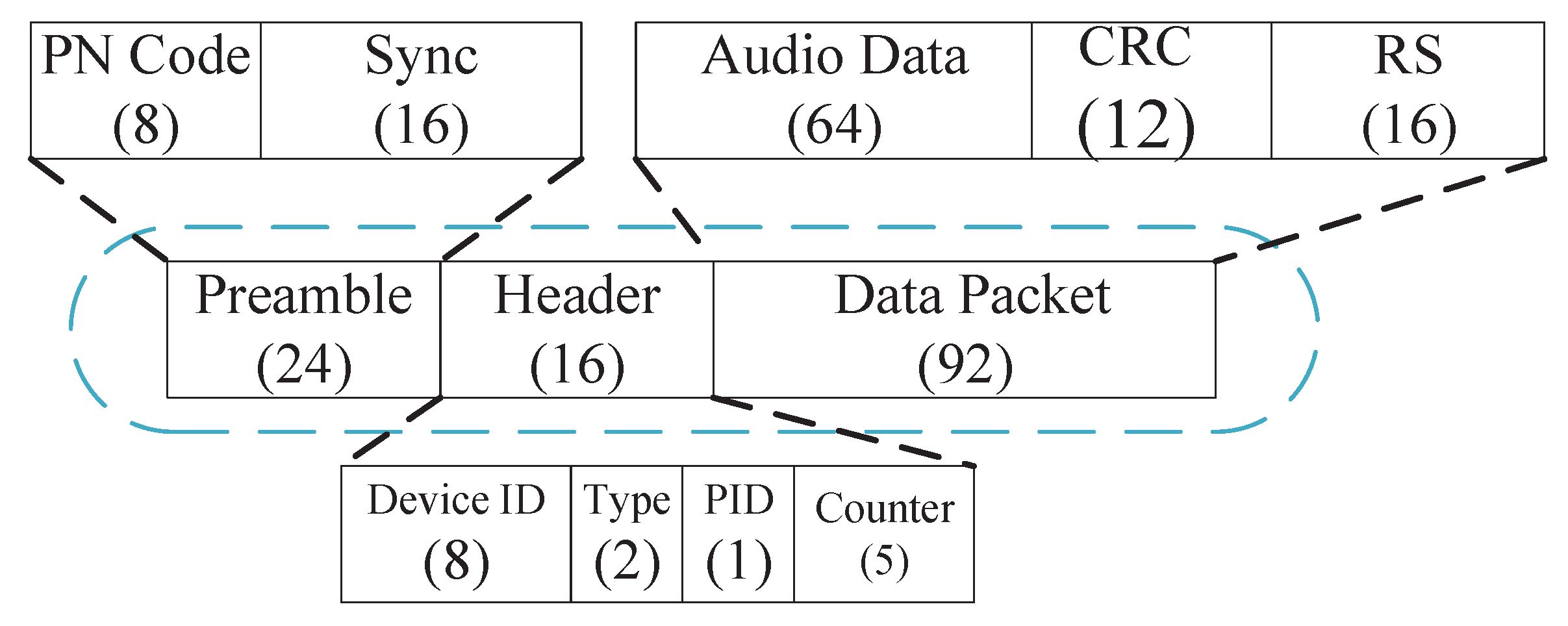
4.2.1. The Packet Definition
The packet definition has been designed for minimum delay with excellent detection error abilities, as shown in
Figure 10. A complete packet consists of three parts: the packet preamble, the packet header, and packet data. The same data structure is used in both systems, i.e., from the earpiece side to the MCP and from the computing side to the earpiece side. In order to increase the effective data rate, the packet preamble and the packet header are both as small as possible.
The packet preamble mainly contains two parts: the PNcode and sync. The purpose of the PN code is frequency offset estimation and automatic gain control during receiver demodulation, and the PN code is the 8-bit content sequence. Sync provides receiver clock synchronization, and the receiver uses the correlator to perform correlation matching according to the 16-bit synchronization judgment word defined in the register in advance. When the matched bit number is greater than a certain set value (such as seven), it is considered during synchronization and starts receiving a packet.
The packet header consists of the device ID, the type, the Packet Identification (PID), and the counter. The Device ID is a unique 8-bit code that identifies the individual HA and MCP. The type indicates the type of packet that is sent, such as control data or audio data. The PID is a single bit that normally alternates with each new packet sent, but it only appears if the previous packet header was received correctly and its PID bit has the expected value. If the received PID bit is the same as that in the previously-received packet, retransmission is required. The counter is the easiest and fastest way to judge whether to lose packets.
Packet data contain user data, the Cyclic Redundancy Code (CRC), and Reed–Solomon (RS) code. User data are loaded by the audio data. A 12-bit CRC (polynomial X+X+X+X + X + 1) is adopted to detect errors in each user data block (the user data and the CRC) protected by an RS error-correcting code.
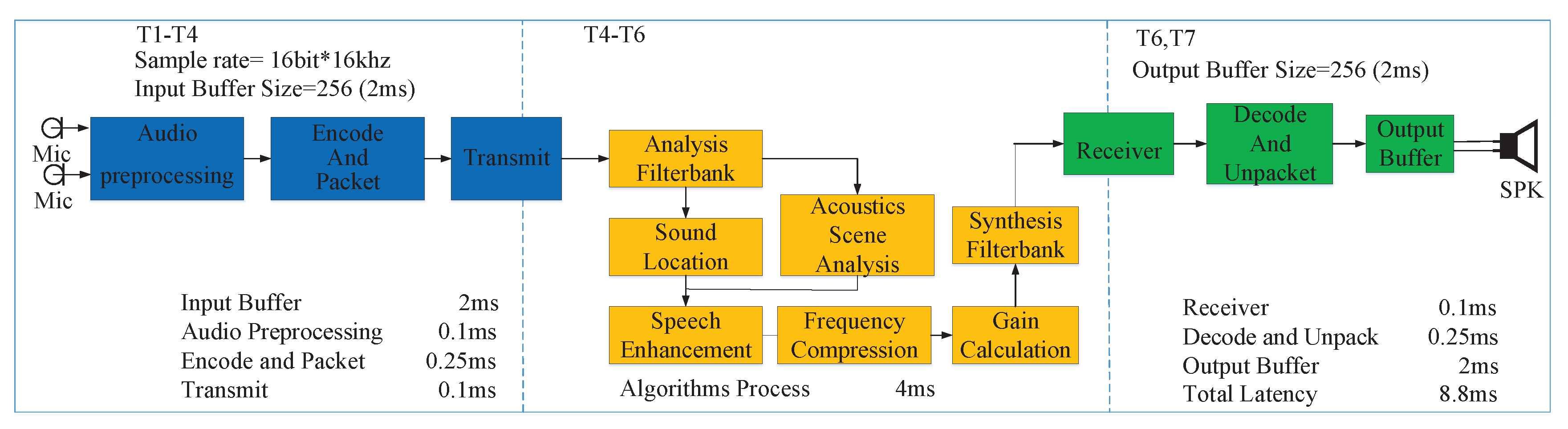
Whenever there is active voice data of 2 ms in the TX_FIFO, “TX_data_already”, a packet is automatically constructed with the preamble and the header. After a complete packet has been successfully constructed and transmitted, this process will be performed continuously and automatically.
4.2.2. Transmit Processing
As shown in
Figure 11a, transmission processing is mainly composed of the following steps: First, the audio data from “TX_fifo” is compressed by the G.726 encoder to reduce the data rate. Then, the controller constructs a data packet whenever there is more than one block of data from Step 1. Finally, A CRC and RS are joined to the data. In this way, a complete data transmission package is constructed and sent to the transmitter device. There are two paths: the first path is to generate the packet preamble and the packet header, while the second path decodes the audio data and CRC RS operations that are required before transmission.
4.2.3. Receive Processing
As shown in
Figure 11b, I and Q signals are received through timing sync and de-shape, while the BADDidentifies the relevant word indicating the start of the packet. De-mapper processing starts after receiving this. The RS decoder performs forward error correction on the entire packet. After error correction, the CRC decodes the data and identifies uncorrectable errors. Data are discarded or retransmitted according to the rules we have established. If the data packet has no wrong block, the restored data of G.726 are stored in “RX_FIFO” for further processing.
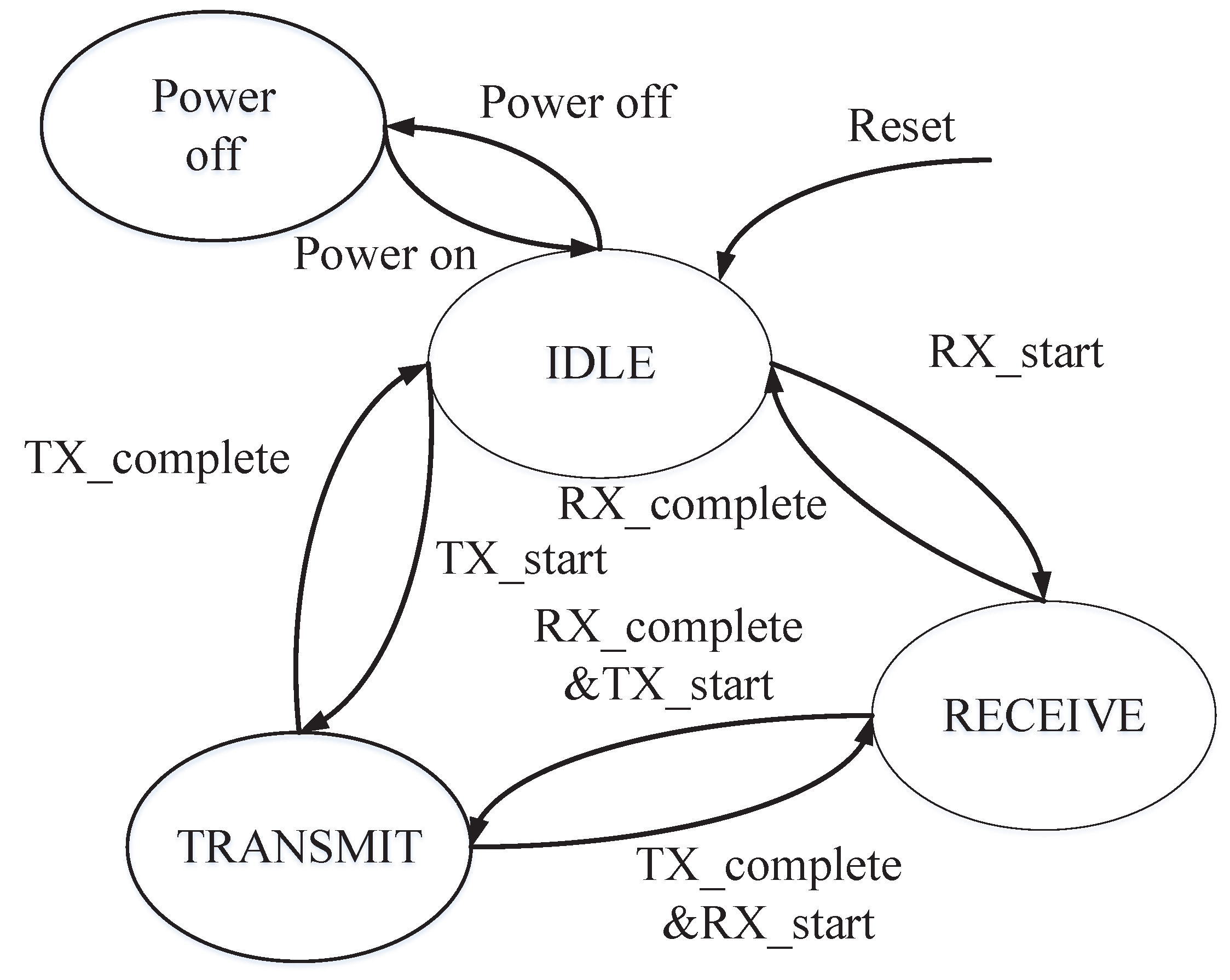
4.2.4. The Operating Scheme
We designed the system as a memory-mapped hardware state machine, which can reduce power consumption. The signal data exchange module control state machine is shown in
Figure 12.
We optimized the operation scheme to reduce the power consumption. Clock gating was used to reduce system power. There are four states: powering off, idling, transmitting, and receiving. In the powering off state, the whole system power is shut down, and there is no power consumption. In the idle state, there is only the controller with the clock, while the other blocks are turned off. In the transmitting and receiving states, the uncorrelated clock of blocks is turned off.
The system default state is power off. When there is power supply and the command “power on” is detected, the idle state appears. The powering off instruction is to close the controller. In the idle state, “TX_start” and “RX_start” refer to entering the transmitting or receiving state, while “TX_complete” and “RX_complete” refer to entering the idle state. In the transmitting state, the instructions “Tx_complete” and “RX_start” are detected simultaneously, and then, it directly jumps to the receiving state. Similarly, in the receiving state, it can jump directly to the Transmitting state.
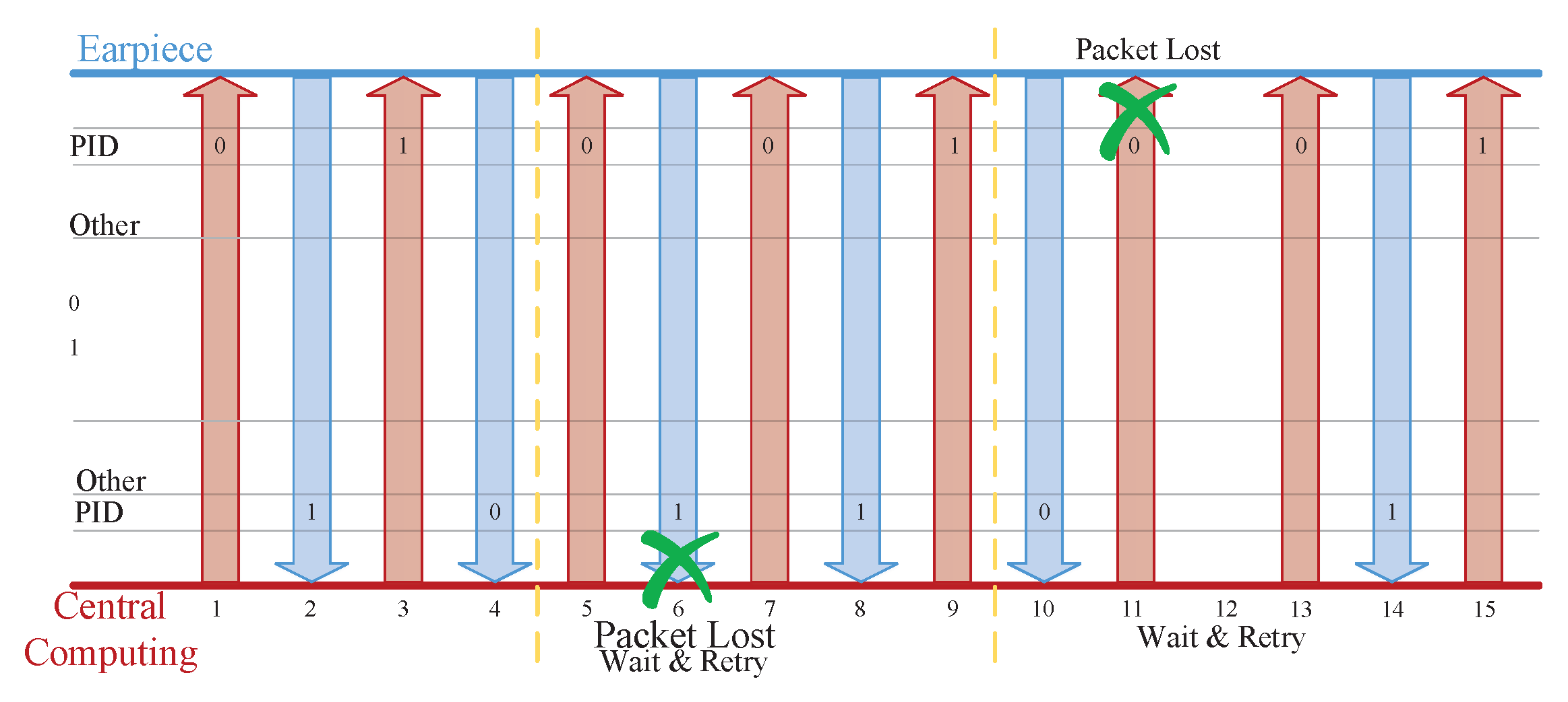
4.2.5. Packet Exchange
As already described in the packet structure definition, we define whether a bit is a Packet Identification (PID), and the role of this bit is mainly to detect whether there is packet loss. When the previous packet header is correctly received and its PID bit has the expected value, this bit will be inverted when the next transmission is performed. If the received PID bit is not expected, this may also be considered as packet loss. As shown in
Figure 13, T (Time)1–T4 show the normal packet exchange, where the PID bits sent in each direction alternate between zero and one. T5–T9 show one of two ways of losing packets, whereby the earpiece has received a packet from the MCP with the same PID as that in the previously-received packet. This PID shows that the MCP did not receive the last packet. Another way of losing packets is shown in T10–T15, whereby the MCP has not received a response packet from the earpiece within the configured timeout (the adjustable preset value in the register). Then, the MCP will repeat the last sent packet without changing the PID bit, until receiving the response from the earpiece.
4.3. Digital to Electronic Module
The digital-to-analog converter and the up-sampling and output driver constitute the digital-to-electronic module, which converts digital pure audio data to analog signals; the housing speaker regenerates the voice playback.

 ,
, 


