Article

Dynamic Rotated Angular Beamforming Using Frequency Diverse Phased-Array for Secure MmWave Wireless Communications

1
Key Laboratory of Trustworthy Distributed Computing and Service (BUPT), Ministry of Education, and School of Information and Communication Engineering, Beijing University of Posts and Telecommunications, Beijing 100876, China
2
School of Physics and Mechanical and Electrical Engineering, Shaoguan University, Shaoguan 512005, China
*
Author to whom correspondence should be addressed.
Electronics 2020, 9(1), 10; https://doi.org/10.3390/electronics9010010
Submission received: 21 November 2019 / Revised: 15 December 2019 / Accepted: 18 December 2019 / Published: 21 December 2019
(This article belongs to the Section Microwave and Wireless Communications)

Abstract

:
In this paper, we propose a new secure millimeter-wave wireless communication architecture called dynamic rotated angular beamforming (DRAB), to address the physical layer security (PLS) challenge for aligned transmitter, eavesdropper and target receiver in the mainlobe path, where the conventional angular beamforming (CAB) fails to provide satisfactory PLS performance. The proposed DRAB consists of a conventional phased-array and a set of frequency offset modulator. A frequency offset increment (FOI) set is intentionally introduced to control the dynamic rotation of DRAB’s mainlobe around the target user in the angle-range space. Thus, the average sidelobe of DRAB outside the target region is suppressed dramatically while the mainlobe inside the target region is a constant. We consider two cases of interests, i.e., with/without the location information of eavesdropping. For the known eavesdropping case, DRAB steer the zero gain sidelobes towards eavesdropper. The secrecy rate maximization problem is simplified to a form only depending on the FOI. As for the unknown eavesdropping case, we mainly depends on the beam rotating dynamically and randomly to hide the mainlobe path. Moreover, we propose inverted antenna subset technique to further randomize the sidelobes against sensitive eavesdropping. Numerical simulations demonstrate that the proposed DRAB can provide superior PLS performance over the existing CAB.

1. Introduction

The broadcast nature of wireless medium makes wireless systems vulnerable to eavesdropping. Recently, physical layer security (PLS) technique which is an information theoretic method to achieving secure wireless communications without upper-layer encryptions has received more and more attentions [1,2,3,4]. Sidelobe suppression and sidelobe randomization are the popular PLS approaches [5,6,7,8] in transmit beamforming, which provide satisfactory secure performance by decreasing and jamming eavesdropper’s reception while keeping target user’s (Bob’s) reception constant. If an eavesdropper (Eve) locates in the sidelobe angle sector, PLS can be achieved easily. Especially in band above millimeter-wave (mmWave), the highly directional transmit beamforming makes information leakage in the sidelobe region almost negligible. However, as conventional angular beamforming (CAB) is only angle-dependent beampattern, the transmitter (Alice) can not discriminate Bob and Eve with different range in the same target direction. Thus, these PLS approaches may fail in the challenge scenario where the channels of Eve and Bob are highly correlated and the path-loss of Eve is weaker than Bob. As shown in Figure 1, only if Eve captures the fixed mainlobe direction of CAB and moves in the beam direction, confidential information leakage is inevitable.
In recent years, the research on solving mainlobe path threat for PLS has ramped up markedly. The work in [9] develops an intelligent reflecting surface (IRS)-aided secure wireless communication system, where the extra IRS is deployed in the vicinity of Bob and Eve. By jointly optimizing the active transmit beamforming of Alice and the passive reflect beamforming at the IRS, the secrecy rate for Bob can be maximized. In order to achieve PLS for directionally-aligned Alice, Eve and Bob in the mainlobe path, some angle-range-dependent transmit beamforming schemes [10,11,12,13] are proposed to discriminate Bob and Eve in the target direction. The work in [10] proposes a location-based PLS technique for vehicular networks in mmWave communication by exploiting the large dimensional antenna arrays and the ground-reflected path to achieve angle-range-dependent transmission and sidelobe randomization. The works in [11,12] propose a frequency diverse phased-array (FDPA) beamforming approach to achieve PLS for proximal or aligned target user and well-localization eavesdropper. The work in [13] proposes an optimal FDPA directional modulation with artificial noise (AN) scheme to decouple the angle-range correlation and maximize the secrecy rate (SR) of Bob.
In this paper, we propose a novel dynamic rotated angular beamforming (DRAB) to address the challenge of PLS in the CAB by exploiting the frequency degree of freedom (DoF) of FDPA. As shown in Figure 1, we consider the secure communication from Alice to Bob, and Eve maybe locate in any region except target region ( θ T , R T ) , including the challenging scenarios of aligned Alice, Eve and Bob, or proximal Bob and Eve. By elaborately calculating the set of frequency offset increment (FOI) across FDPA antennas, DRAB can steer the minimum sidelobes towards a well-localization eavesdropper. Moreover, the mainlobe path can randomly rotate around the target user against the unlocalization eavesdropper. The sidelobe randomization technique of inverted antenna subset dynamic rotated angular beamforming (IAS-DRAB) is further proposed to tackle the sensitive eavesdropping. Thus, no matter whether Alice has the eavesdropping location information or not, DRAB can address conventional PLS challenge and provide satisfactory PLS performance.
Compared with the existing works of solving the security threat on the mainlobe path, our proposed DRAB highlights itself in two aspects, i.e., the system method and the application scenarios, as illustrated in Table 1. Firstly, we only need design the transmit beamforming to achieve secure secure communication. The target receiver is transparent to our proposed DRAB as it is not affected by the techniques of beampattern rotation and sidelobe randomization. While the existing work in [9] needs add an extra auxiliary equipment of IRS, and the receiver in [10] needs conjugate the reflected signal to demodulate the secure information. Secondly, our proposed DRAB consider both scenarios with and without eavesdropping location information. While the existing FDPA-based transmission beamforming in [11,12,13] mainly consider the case with eavesdropping location information. More explicitly, the main contributions and new features of this paper are summarized as follows.
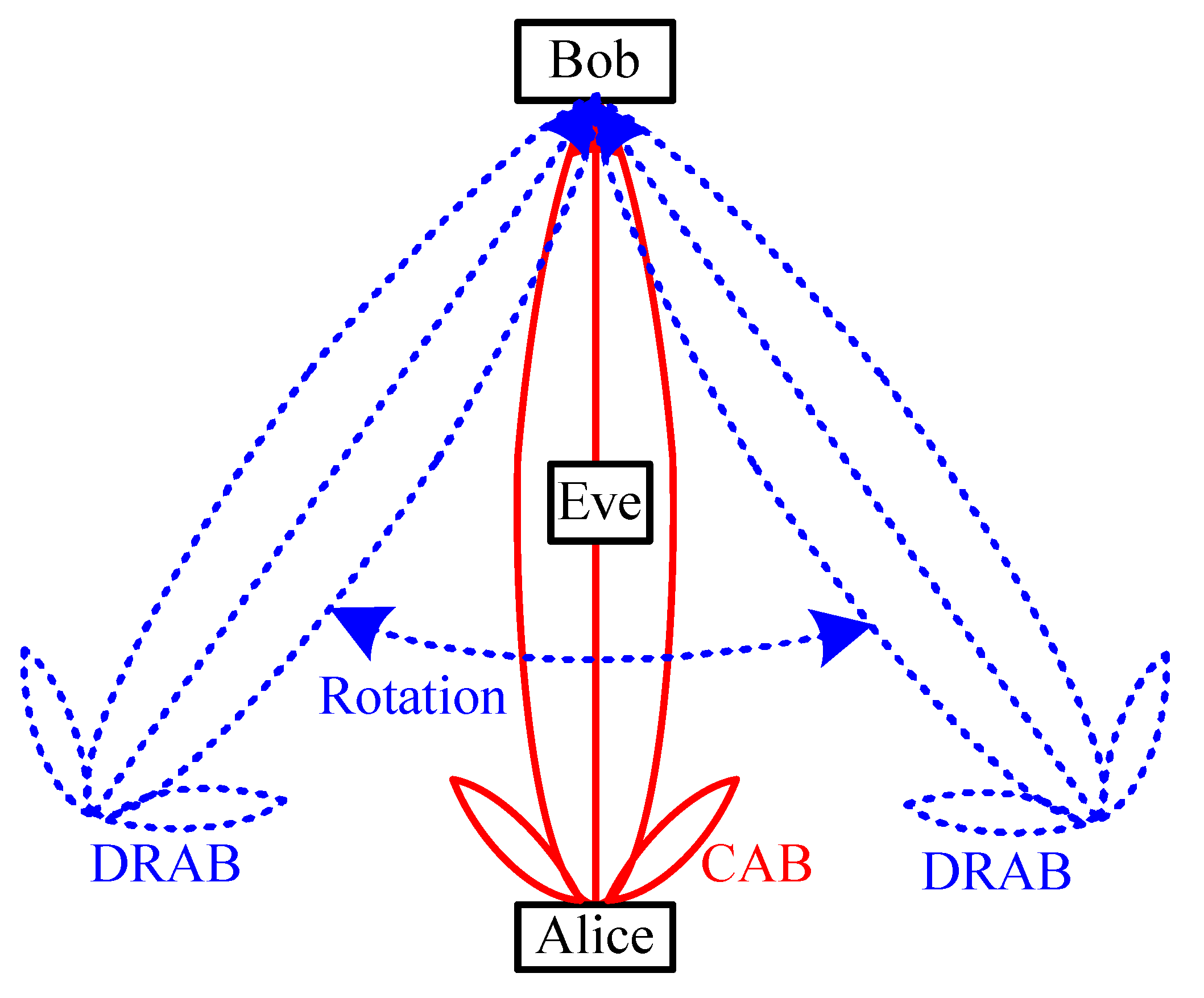
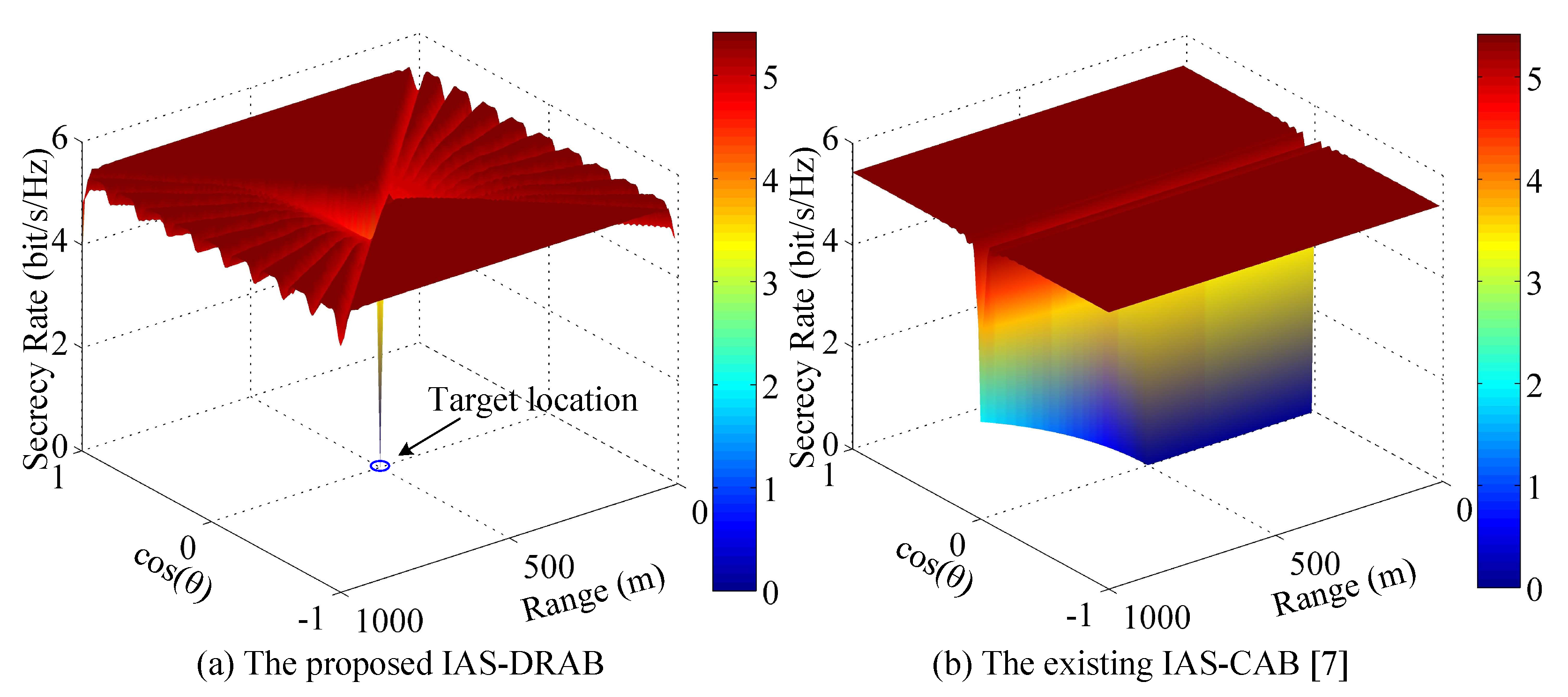
  • We propose a novel FDPA-based DRAB transmission scheme to address the secure problem of mainlobe path. Compared with the existing CAB that can not discriminate, the eavesdropper in the target direction, our proposed DRAB is an angle-and-range double confined beam, which can circumvent the eavesdropper to steer the mainlobe by exploiting the DoF of frequency. Especially, the well-localization eavesdropper can be pointed by the zero gain sidelobe through an elaborate FOI across the FDPA.
  • In order to avoid the rotatable mainlobe path being captured by the unlocalization eavesdropper, we propose a random dynamic rotation method of beampattern. The average beampattern of DRAB is derived as a function of FOI. The average mainlobe is only focused on the target region and the average sidelobes outside the target region are suppressed remarkably. As a beneficial result, the security threat in the mainlobe path of CAB can be alleviated.
  • We also propose a DRAB-based IAS scheme to further randomize the sidelobe against sensitive eavesdropper by exploiting the DoF of digital phase shifter in FDPA, where some elements of beam steering weight vector are randomly selected with same probability to shift an extra phase π . Thus, in the sidelobe region, the AN is produced to interfere with the sensitive eavesdropper and the PLS performance is improved.
Organization: the remainder of this paper is organized as follows. The elements of the proposed DRAB transmission is introduced in Section 2. In Section 3, we analyze the PLS performance of DRAB. The simulation results are given in Section 4. Finally, we conclude our works in Section 5.
Notation: boldface uppercase and lowercase letters denote matrices and vectors, respectively. The parameter a i represents the i-th element of the vector a, ab indicates Hadamard product of two vector a and b, N ( μ , σ 2 ) / CN ( μ , σ 2 ) is the real/complex Gaussian random distribution with mean μ and variance σ 2 . [ · ] T is transpose, [ · ] * is conjugate and transpose. N , Z , R and C denote natural, integer, real and complex numbers, respectively, E [ · ] and var [ · ] denote expectation and variance, respectively. · and · round the argument to the nearest integer towards and ∞, respectively. [ · ] + denotes max ( 0 , [ · ] ) .

2. DRAB Transmission Technique

2.1. System Model

As shown in Figure 2, DRAB consists of a N-antenna conventional phased-array (CPA) plus a frequency offset modulator at each branch. The bits of secret information are modulated in the baseband domain. Then the baseband signal is up-converted by f c through the radio frequency mixer, and divided into N signal copies. Each copy is converted again by an extra tiny frequency offset before phase shifting. Finally, the phase shifted signal is amplified by a power amplifier and loaded to the antenna.
For simplicity, we consider a multiple-input single-output (MISO) mmWave wireless communication system with a N-antenna transmitter and a single antenna receiver in the line-of-sight (LoS) environment. N-antenna is deployed to a uniform linear array with an inter-element space of d 0.5 λ , and λ is the wavelength. The receiver can only distinguish the azimuth angle θ . Alice knows the exact locations ( θ T , R T ) of Bob. We only consider the directional LoS channel since the multi-path components are very few and relatively weak in mmWave transmission [14,15,16], which can be ignored.
The received signal at any location ( θ , R ) is written as
y ( θ , R ) = P T P L G R h * w ( θ T , R T ) x + η = P T P L G R B ( θ , R ) x + η ,
where P T , P L and G R are the transmission power, path-loss factor and received power factor, respectively, h C N × 1 is the channel vector, w C L × 1 is the transmit beamforming vector, B = h * w denotes the array factor at location ( θ , R ) , x is the modulated transmit signal with E [ | x | 2 ] = 1 , and η is the additive white Gaussian noise (AWGN) with zero mean and σ 2 variance, i.e., η N ( 0 , σ 2 ) .

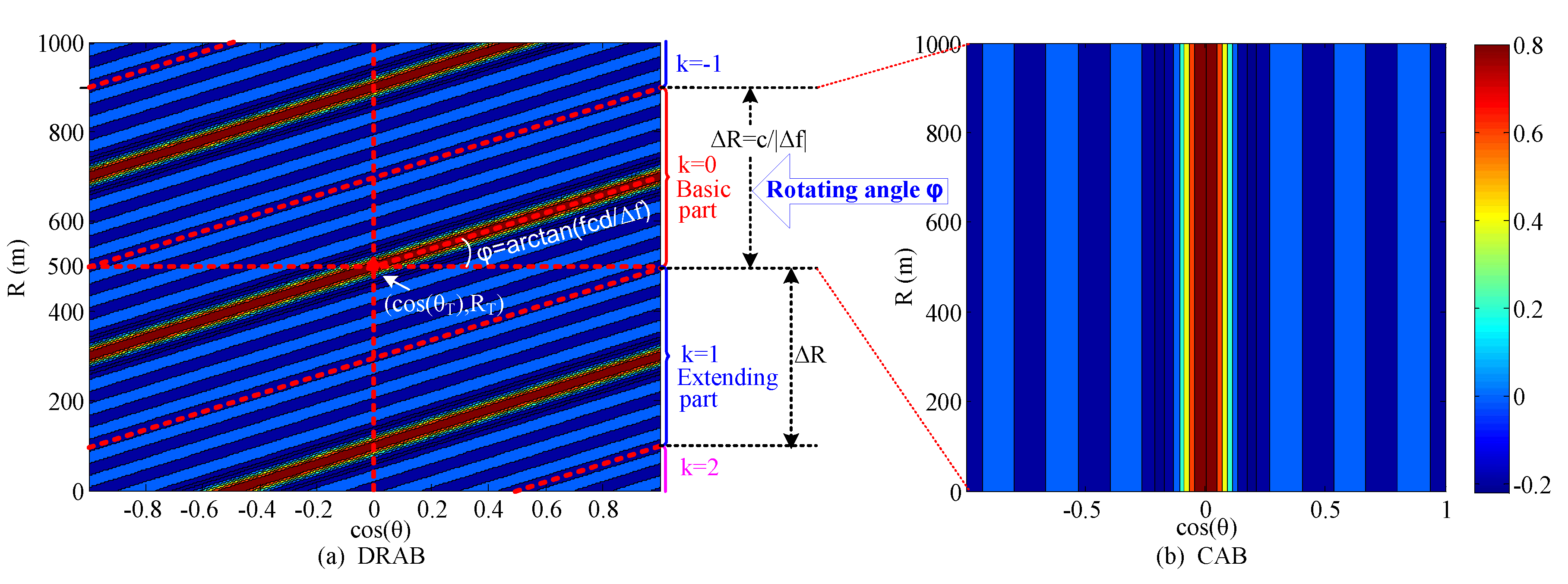
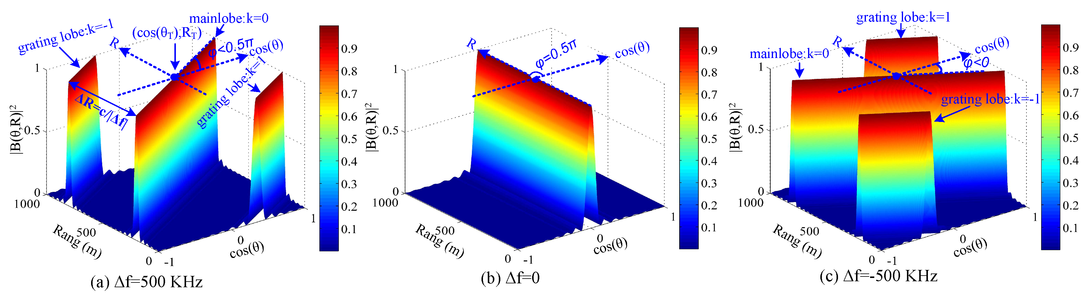
2.2. Dynamic Rotated Angular Beamforming

In Figure 2, the frequency offset increment (FOI) Δ f is the frequency difference between the ( n + 1 )th element and the nth element, i.e., Δ f = f n + 1 f n , n . Thus, the radiated frequency of the nth antenna in the FDPA is expressed as
f n = f c 0.5 ( N 1 2 n ) Δ f , n = 0 , 1 , , N 1 ,
where f c and Δ f denote the carrier frequency. In the special case of Δ f = 0 , the FDPA becomes a single frequency phased-array, i.e., f n = f c , n , and the proposed DRAB is degraded to the conventional angular beamforming.
Assume ( θ , R ) is a far-field location far away from the array center. The propagation range from the n-th element to the location ( θ , R ) is expressed as
R n = R + 0.5 ( N 1 2 n ) d cos θ .
The phase difference between the nth element and the reference is written as
Δ Φ n = 2 π f n R n c 2 π f c R c = 2 π ( N 1 2 n ) f c d cos θ c 2 π ( N 1 2 n ) R Δ f c 2 π ( N 1 2 n ) 2 Δ f d cos θ c ,
where c is the speed of light. Note that on the right hand side of (4), the first term is angle-dependent, the second term represents the range-dependent feature of DRAB and the third term can be neglected when 0.5 ( N 1 ) Δ f f c [17]. The channel vector of DRAB is denoted as
h * ( θ , R ) = e j ( N 1 ) π c ( f c d cos θ R Δ f ) , e j ( N 3 ) π c ( f c d cos θ R Δ f ) , , e j ( N 1 ) π c ( f c d cos θ R Δ f ) .
Then, the array factor of FDPA-based DRAB is expressed as
B ( θ , R ) = h * ( θ , R ) w ( θ T , R T ) = n = 0 N 1 e j ( N 1 2 n ) π c ( f c d ( cos θ cos θ T ) Δ f ( R R T ) ) N = sin N π f c d ( cos θ cos θ T ) c N π Δ f ( R R T ) c N sin π f c d ( cos θ cos θ T ) c π Δ f ( R R T ) c = sin ( N x ) N sin ( x ) ,
where x = π f c d ( cos θ cos θ T ) c π Δ f ( R R T ) c , w ( θ T , R T ) = h ( θ T , R T ) N is the steering weight vector, and ( θ T , R T ) denotes the target location. Notice that FDPA-based DRAB can be simplified to the CPA-based CAB by setting Δ f = 0 . Thus, the array factor of CPA-based CAB is denoted as
B ( θ ) = sin N π f c d ( cos θ cos θ T ) c N sin π f c d ( cos θ cos θ T ) c .
From the Equations (6) and (7), we know that the beampattern of DRAB is angle-range-dependent while the CAB is angle-dependent but range-independent. The distribution feature of DRAB beampattern is demonstrated in Figure 3 and summarized in Lemma 1.
Lemma 1.
Assume ( θ T , R T ) is the origin of the cos θ -R plane. The beampattern of FDPA-based DRAB derives from the CAB’s beampattern rotated an angle φ and then periodically extended along the R-axis. The beampattern path of DRAB corresponding to the beampattern | B ( θ C A B ) | of CAB is expressed as
R = R T + f c d ( cos θ cos θ C A B ) Δ f + k c Δ f , k Z .
The rotated angle φ between the beampattern path of DRAB and the cos θ -axis is formulated as
φ = arctan f c d Δ f .
The range difference between the mainlobe and the most adjacent grating lobe is expressed as
Δ R = c | Δ f | .
Proof. 
See Appendix A. □
As shown in Figure 3a, the beampattern of DRAB consists of the basic part and the extending part, corresponding to k = 0 and k 0 , respectively. The basic part is the beampattern of CAB in Figure 3b after rotation by an angle φ along the line R = R T , and the extending part is the periodic copy of the basic part.
Based on the Lemma 1, we have some interesting observations which are summarized by the following corollaries.
Corollary 1.
The beampattern | B ( θ , R ) | is a periodic function along the R-axis in the cos θ -R plane, expressed as
| B D R A B ( θ , R + c Δ f ) | = | B D R A B ( θ , R ) | .
Proof. 
See Appendix B. □
Corollary 2.
In the cos θ -R plane, only the mainlobe path of DRAB traverses the target location ( θ T , R T ) , which is formulated as
R = R T + f c d Δ f ( cos θ cos θ T ) .
The grating lobe paths of DRAB parallel with the mainlobe path, denoted as
R = R T + f c d Δ f ( cos θ cos θ T ) + k c Δ f , k Z , k 0 .
The zero gain sidelobe path of DRAB is expressed as
R = R T + f c d Δ f ( cos θ cos θ T ) + k c N Δ f , k N Z , k Z .
Proof. 
See Appendix C. □
As shown in Figure 4, DRAB can generate countless grating lobes along the R-axis as R increases, which may bring new secure communication problem. However, in practice, the impact of grating lobes, especially the grating lobes of large | k | , can be neglected considering the severe path-loss of mmWave. As shown in Table 2, the path-loss P L ( R ) (According the NYC experimental result [18] in mmWave communications, the path-loss can be modeled with a log-distance model, which is denoted as P L ( R ) = 69.8 + 20 log 10 ( R ) [dB].) of the grating lobes increases more than 20 dB when | k | increases from 0 to 5.
Therefore, the impact of grating lobe of DRAB for secure communication is controllable. The security threat of the grating lobes can be relieved by setting Δ R R T .
Corollary 3.
Assume { | Δ f | c 2 R T , d 0.5 λ , θ T = 90 0 } or { | Δ f | c 2 R T , d 0.25 λ } , then, Δ R 2 R T . Only the mainlobe of DRAB emerges inside the region of 0 θ 180 0 and 0 < R < 2 R T , and the grating lobes emerge outside this region.
Proof. 
See Appendix D. □
Remark 1.
According to the above lemma and corollaries, the beampattern of DRAB can be rotated flexibly around the target receiver by adjusting Δ f . For well-localization eavesdropping, DRAB can steer zero gain sidelobe towards the eavesdropper to improve the secure performance. Thus, the mainlobe of DRAB circumvents the known eavesdropper and the PLS achieves.
However, DRAB still confronts another security threat as the mainlobe or grating lobe is only rotated to another direction which may be captured by another eavesdropper. To this end, we further study the method of hiding the mainlobe and grating lobes with multiple FOIs.

2.3. Average Beampattern of DRAB

Assume Δ f m a x and Δ f m i n denote the maximum FOI and minimum FOI of DRAB, respectively, i.e., Δ f m i n Δ f Δ f m a x . Dividing the interval [ Δ f m i n , Δ f m a x ] into ( M 1 ) parts with equal intervals δ , we get the FOI set Ω Δ f = { Δ f m i n , Δ f m i n + δ , , Δ f m i n + ( M 1 ) δ } , and Δ f m a x = Δ f m i n + ( M 1 ) δ . Then, Δ f Ω Δ f . The intervals δ is expressed as
δ = Δ f m a x Δ f m i n M 1 .
The rotation angle φ of DRAB jumps randomly when the FOI Δ f is selected from the set Ω Δ f with same probability, which is called as dynamic rotated angle beamforming. The average beampattern of DRAB at any location ( θ , R ) is expressed as
| B ¯ ( θ , R ) | 2 = m = 0 M 1 | B ( θ , R ) | 2 M = m = 0 M 1 sin 2 N π f c d ( cos θ cos θ T ) c N π ( Δ f m i n + m δ ) ( R R T ) c M N 2 sin 2 π f c d ( cos θ cos θ T ) c π ( Δ f m i n + m δ ) ( R R T ) c .
According to Corollary 2, only the mainlobe path of DRAB traverses the target location ( θ T , R T ). Then, the average beampattern inside the target location is enhanced to 1 as | B ( θ T , R T ) | = 1 , m , in (16). While the average beampattern outside the target is suppressed to less than 1 since | B ( θ , R ) | 1 .
Obviously, increasing M deceases the average beampattern outside the target location and increases the randomness of rotation angle φ . Thus, the security threat of mainlobe or grating lobe path is relieved. As the beampattern | B ( θ , R ) | 2 is a continuous function in the interval [ Δ f m i n , Δ f m a x ] , the average beampattern converges when M tends to infinity, denoted as follows,
| B ¯ ( θ , R ) | 2 = lim M m = 0 M 1 | B ( θ , R ) | 2 M = lim M δ 0 1 M δ m = 0 M 1 | B ( θ , R ) | 2 δ = 1 Δ f m a x Δ f m i n Δ f m i n Δ f m a x sin 2 N π f c d ( cos θ cos θ T ) c N π Δ f ( R R T ) c N 2 sin 2 π f c d ( cos θ cos θ T ) c π Δ f ( R R T ) c d Δ f = 1 Δ f m a x Δ f m i n Δ f m i n Δ f m a x | B ( θ , R ) | 2 d Δ f .
As shown in Figure 5, DRAB generates very low average sidelobes outside the target location ( cos θ T , R T ) , and the average mainlobe only focuses on the target location. Thus, the mainlobe path security problem that is inherent in the CAB can be solved.
Remark 2.
As the mainlobe path is rotated dynamically and randomly around the target receiver, it is impossible that an eavesdropper outside the target location always can capture each mainlobe path. However, an sensitive eavesdropper with very high receiver gain can still intercept the confidential information through nonzero gain sidelobes. Thus, we further propose IAS-aided sidelobe randomization technique against sensitive eavesdropping.

2.4. IAS-Based Sidelobe Randomization

In Figure 2, let Υ π be a random subset of N 1 antenna used to shift an extra phase π , Υ 0 be a subset that contains the remaining ( N N 1 ) antennas whose phase is not extra changed [16]. Thus, the nth element of steering weight vector in (6) is denoted as
w n = e j π c ( N 1 2 n ) ( f c d cos θ T R T Δ f ) + π N 2 N 1 e j π c ( N 1 2 n ) ( f c d cos θ T R T Δ f ) N 2 N 1 = e j π c ( N 1 2 n ) ( f c d cos θ T R T Δ f ) N 2 N 1 , n Υ π e j π c ( N 1 2 n ) ( f c d cos θ T R T Δ f ) N 2 N 1 , n Υ 0 .
Then, the steering weight vector w of IAS-based DRAB can be denoted as w = 1 N 2 N 1 [ b h ( θ T , R T ) ] , n . b B is a N × 1 vector with element b n { 1 , 1 } , and B is the set of all possible antenna subset combinations. The nth element b n of b is a Bernoulli random variable, denoted as
b n Bern N 1 N = 1 w . p . N 1 N 1 w . p . N N 1 N , n = 0 , 1 , , N 1 .
Then, E [ B n ] = N 2 N 1 N , E [ B n 2 ] = 1 , var [ b n ] = E [ B n 2 ] | E [ B n ] | 2 = 4 N 1 N 4 N 1 2 N 2 . The array factor of IAS-based DRAB is a random variable, denoted as
B I A S ( θ , R ) = h * ( θ , R ) [ b h ( θ T , R T ) ] N 2 N 1 = 1 N 2 N 1 n = 0 N 1 b n e j π ( N 1 2 n ) ( f c d ( cos θ cos θ T ) Δ f ( R R T ) ) c = 1 N 2 N 1 n = 0 N 1 b n e j ( N 1 2 n ) x .
Lemma 2.
For a large number N and R R + f c d Δ f ( cos θ cos θ T ) + k c Δ f , k Z , B I A S ( θ , R ) converges to a complex Gaussian random variable with mean
E [ B I A S ( θ , R ) ] = sin ( N x ) N sin ( x ) = B ( θ , R ) ,
and variance
var [ B I A S ( θ , R ) ] = 4 N 1 ( N N 1 ) N ( N 2 N 1 ) 2 .
Proof. 
See Appendix E. □
According to Equation (1) and Lemma 2, the noise-free received signal y ( θ , R ) of IAS-based DRAB is also a complex random variable with mean E [ y ( θ , R ) ] = P T P L G R B ( θ , R ) and variance var [ y ( θ , R ) ] = P T P L G R var [ B I A S ( θ , R ) ] . Thus, the artificial noise (AN) power P A N generated by IAS is expressed as
P A N = 0 , if R = R T + f c d Δ f ( cos θ cos θ T ) + k c Δ f , k Z P T P L G R 4 N 1 ( N N 1 ) N ( N 2 N 1 ) 2 , otherwise .
Since the proposed IAS-based DRAB randomizes the sidelobes and produces AN to interfere with the eavesdropper in the sidelobe region, the sensitive eavesdropping problem is solved. Thus, the PLS performance is further improved.

3. PLS Performance Analysis

In this section, we analyze the PLS performance of the proposed DRAB scheme in mmWave wireless communications focusing on two cases of interests, namely with/without the location information of eavesdropping.

3.1. Secrecy Rate

The signal-to-noise ratio (SNR) of DRAB at any region is defined as
S N R ( θ , R ) = P T P L G R | B ( θ , R ) | 2 σ 2 = r | B ( θ , R ) | 2 ,
where r = P T P L G R σ 2 is the SNR without considering the beamforming factor.
The SR is the achievable rate difference between Bob and Eve, denoted as
R S ( θ , R ) = log ( 1 + S N R ( θ T , R T ) ) log ( 1 + S N R ( θ , R ) ) + = log 1 + r T | B ( θ T , R T ) | 2 1 + r E | B ( θ , R ) | 2 + .
In the proposed DRAB transmission scheme, the average beampattern gain is mainly determined by the FOI Δ f and the array parameters. We assume that Bob can be located accurately and the signal energy of the confidential information is intentionally focused on Bob’s location. Then, the average beampattern gain of Bob is a constant. Thus, the PLS problem boils down to steer minimum sidelobe resultant gain towards Eve by selecting the FOI Δ f and generate AN against sensitive eavesdropping.
Our target is to achieve optimal SR for Bob with the proposed DRAB under two cases of interests of with/without location information of eavesdropping, which is expressed as follows.

3.2. Case 1: With Eavesdropping Location Information

If Alice gets the exact information of eavesdropping location ( θ E , R E ) , she can steer minimum gain sidelobes towards the well-localization eavesdropper, which is expressed as
Δ f * = arg min | B ( θ E , R E ) | 2 , s . t . ( θ , R ) ( θ T , R T ) .
According to the zero sidelobe path of Equation (14) in Lemma 2, we have
Δ f k * = f c d ( cos θ E cos θ T ) R E R T + k c N ( R E R T ) , s . t . ( θ E , R E ) ( θ T , R T ) , k Z , k N Z , Δ f m i n Δ f k * Δ f m a x .
Then, we get the FOI set of zero sidelobe on the location ( θ E , R E ) , which is denoted as
Ω 0 = { Δ f k * | k Z , K m i n k K m a x } ,
K m i n = N ( R E R T ) c Δ f m a x f c d ( cos θ E cos θ T ) R E R T , R E < R T N ( R E R T ) c Δ f m i n f c d ( cos θ E cos θ T ) R E R T , R E > R T ,
K m a x = N ( R E R T ) c Δ f m i n f c d ( cos θ E cos θ T ) R E R T , R E < R T N ( R E R T ) c Δ f m a x f c d ( cos θ E cos θ T ) R E R T , R E > R T .
As B ( θ E , R E ) | Δ f Ω 0 = 0 , then, S N R ( θ E , R E ) = 0 and the SR is maximum.
Define secure critical range (SCR) R s c r as the range difference between the target location and the most adjacent zero sidelobe in the target direction θ = θ T . According to (14) in Corollary 2, we can derive the expression of SCR as follows,
R s c r = min | R z e r o R T | = c N | Δ f | ,
where R z e r o is the range on the zero gain sidelobe in (14). R s c r decreases as | Δ f | and N increase. Therefore, the proposed DRAB can maintain maximum SR when | R R T | R s c r .

3.3. Case 2: Without Eavesdropping Location Information

In this case, the position of eavesdropper with a high gain receiver is unknown. In order to provide robust PLS performance against the sensitive eavesdropper without eavesdropping location information, we further propose inverted antenna subset of dynamic rotated angular beamforming (IAS-DRAB) technique to randomize the sidelobe and hide the mainlobe path. IAS-DRAB selects the FOI Δ f m from M-element set Ω Δ f = { Δ f 0 , Δ f 1 , , Δ f M 1 } with same probability.
According to Equations (16) and (21), the average beampattern power of IAS-DRAB is denotes as
| B ¯ I A S D R A B ( θ , R ) | 2 = m = 0 M 1 | E [ B I A S ( θ , R , Δ f m ) ] | 2 M = m = 0 M 1 | B ( θ , R , Δ f m ) | 2 M 1 ,
where B ( θ , R , Δ f m ) = B ( θ , R ) | Δ f = Δ f m in (6). The average power of IAS-DRAB-based AN is expressed as
P ¯ A N = P T P L G R m = 0 M 1 4 N 1 ( N N 1 ) ϵ m M N ( N 2 N 1 ) 2 = 0 , if ( θ , R ) = ( θ T , R T ) P T P L G R 4 N 1 ( N N 1 ) N ( N 2 N 1 ) 2 , else if R R T + f c d Δ f m ( cos θ cos θ T + k c Δ f m ) , k Z , m P T P L G R 4 N 1 ( N N 1 ) ( M 1 ) M N ( N 2 N 1 ) 2 , otherwise ,
where ϵ m = 1 when ( θ , R ) belongs to the sidelobe of Δ f m -DRAB or ϵ m = 0 when ( θ , R ) belongs to the mainlobe or grating lobe of Δ f m -DRAB. According to Corollary 2, if ( θ , R ) = ( θ T , R T ) , then ϵ m = 0 , m . If ( θ , R ) ( θ T , R T ) , the eavesdropper locates on at most one of the mainlobe or grating lobe path. In the sidelobe region, ϵ m = 1 , m .
The average signal-to-interference-plus-noise ratio (SINR) of IAS-DRAB is derived as
S I N R ¯ ( θ , R ) = P T P L G R | B ¯ I A S D R A B ( θ , R ) | 2 P ¯ A N + σ 2 = r E | B ¯ I A S D R A B ( θ , R ) | 2 1 + r E m = 0 M 1 4 N 1 ( N N 1 ) ϵ m M N ( N 2 N 1 ) 2 ,
where r E = P T P L G R σ 2 is Eve’s SNR without considering the beamforming factor. For a sensitive eavesdropper with r E , we have
lim r E S I N R ¯ ( θ , R ) = | B ¯ I A S D R A B ( θ , R ) | 2 m = 0 M 1 4 N 1 ( N N 1 ) ϵ m M N ( N 2 N 1 ) 2 .
Remark 3.
The average SINR of IAS-DRAB outside the target region tends to converge when a sensitive eavesdropper increases the SNR r E to infinity. Thus, the SCR may approach zero for larger number N, and the proposed IAS-DRAB can provide robust PLS performance against sensitive eavesdropping.

4. Simulation Results

In this section, we highlight the advantages of the proposed DRAB scheme by comparing the SR performance with the existing CAB scheme through numerical simulation.
Unless otherwise specified, all simulations consider the uniform linear array, the channel model follows Section 2, and the location of Bob is ( θ T , R T ) = ( 90 0 , 500 m ) . We consider a LoS mmWave wireless communication system operating at f c = 73 GHz. We adopt a log-distance model [18] to model the path-loss as
P L ( R ) = α + 10 n log 10 ( R ) [ dB ] ,
where α = 69.8 , n = 2 , R denotes propagation distance in meter.

4.1. DRAB with Eavesdropping Location

In Figure 6, we plot the SR using the PLS scheme with our proposed DRAB and the existing CAB [5,6,7], respectively. We observe that the SR performance of our proposed DRAB is superior to the CAB. The SR of our proposed DRAB almost equals to SR upper bound except that Eve is adjacent to the target location. However, the SR of the CAB deteriorates remarkably when Eve closes to the target direction. Especially, in the mainlobe direction θ = θ T , the SR drops to zero. The reason for these is that the CAB is only angle-dependent beampattern which results in a constant radiation pattern in the angle domain. Thus, Eve can locate in the non-zero sidelobe or mainlobe to wiretap the confidential information. While our proposed DRAB generates angle-range-dependent beampattern by exploiting the frequency DoF to rotate the beampattern. As DRAB can always steer the zero sidelobe towards a well-localization eavesdropper, the high SR performance is achieved.

4.2. IAS-DRAB without Eavesdropping Location

In practice, a vicious eavesdropper can always hide himself to wiretap the confidential information. As Eve’s location is unknown, we use the IAS-based DRAB methods of sidelobe randomization, sidelobe suppression and beampattern rotation to transmit confidential information. In Figure 7a,b, we plot the average SR of the proposed IAS-DRAB and the existing IAS-CAB [7], respectively. We observe that the average SR of our proposed IAS-DRAB always keeps very high level in angle-range space. Only when Eve co-locates with Bob, the SR drops to zero, which is generally not the case in practice. while the existing IAS-CAB has a long zero SR path along target direction where the PLS performance is the worst. The reason for these is that the existing IAS-CAB is only angle-dependent beam which can not discriminate the eavesdropper in the mainlobe direction. Furthermore, the PLS enhancement techniques of sidelobe randomization and sidelobe suppression are invalid in the mainlobe path. Thus, the fixed mainlobe path of IAS-CAB brings serious security threat. However, the mainlobe path of our proposed IAS-DRAB is rotatable and can be hopped randomly, it is almost impossible for eavesdropper to capture the mainlobe. Therefore, the SR performance of our proposed IAS-DRAB is superior to the existing IAS-CAB.

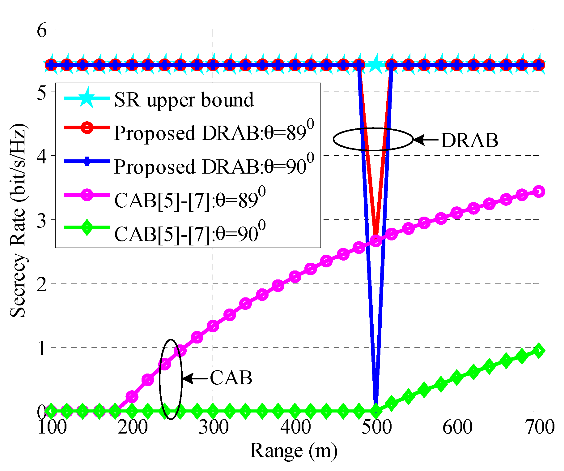
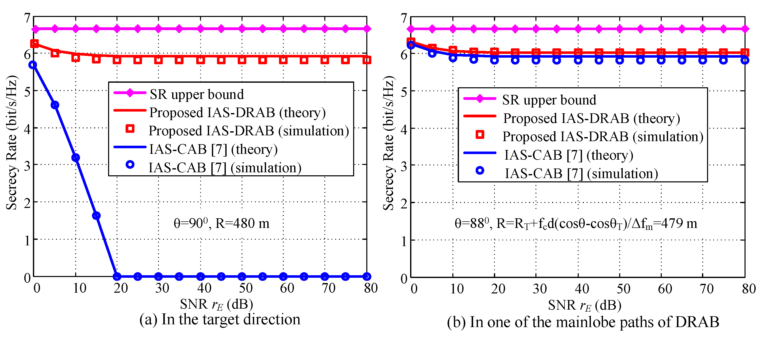
4.3. Robust SR Performance

Assume a sensitive unlocalization eavesdropper can improve the SNR r E defined in (34) to infinity. Figure 8 demonstrates the robustness of SR against sensitive eavesdropping when Bob’s SNR is fixed to r B = 20 dB. In Figure 8a, we firstly select the observation location ( 90 0 , 480 m ) , which is the challenging scenario of θ = θ T and R < R T for PLS in the CAB. The SRs of our proposed IAS-DRAB can keep robust and close to upper bound performance against the increasing of Eve’s SNR. As expected, the SRs of the IAS-CAB drop to zero after r E r B since the sidelobe suppression and sidelobe randomization are useless in this challenging scenario. Then, in Figure 8b, we choose the observation location ( 88 0 , 479 m ) , which is adjacent to Bob and also is in one of the mainlobe path of DRAB. Since IAS-DRAB generates very low average sidelobes and produces AN to disturb eavesdropper outside the target region, the SRs keep high and robust with the increasing of r E , which approximate the SRs of IAS-CAB. Therefore, our proposed IAS-DRAB scheme can provide robust SR performance against sensitive eavesdropping, even in the challenge’s eavesdropping scenario of mainlobe path.

5. Conclusions

This paper proposes a novel DRAB scheme to improve PLS by exploiting the DoF of frequency in mmWave band to hide the mainlobe path, and randomizing the sidelobe to generate AN. The beampattern can be rotated around the target user by adjusting single FOI Δ f . For the case of with eavesdropping location information, DRAB can rotate a zero sidelobe towards the well-localization eavesdropper to achieve secure communication. For the case of without eavesdropping location information and sensitive eavesdropping, DRAB uses a random beampattern rotation method to avoid the mainlobe being captured by eavesdropper, adopts a sidelobe randomization technique of IAS to interfere with potential eavesdropper. The proposed scheme is shown by simulation able to provide high and robust SR performance for known/unknown eavesdropper. Especially in the challenging scenario where the SR of existing CAB drops to zero, the proposed IAS-DRAB can still eliminate zero SR threat and improve PLS performance significantly. Therefore, our proposed scheme can address the challenging problem of PLS for aligned Alice, Eve and Bob.

Author Contributions

Conceptualization, Y.H. (Yuanquan Hong) and X.J.; methodology, Y.H. (Yuanquan Hong) and X.J.; validation, Y.H. (Yuan He), X.J. and J.M.; formal analysis, Y.H. (Yuan He) and J.M.; writing—original draft preparation, Y.H. (Yuanquan Hong); writing—review and editing, Y.H. (Yuanquan Hong), Y.H. (Yuan He) and J.M. All authors have read and agreed to the published version of the manuscript.

Funding

This research was funded by the National Natural Science Foundation of China under Grant 61901049 and the BUPT Basic Research Funding 500419757.

Conflicts of Interest

The authors declare no conflict of interest.

Appendix A

Proof of Lemma 1.
As d 0.5 λ , | Δ f | f c and Δ f 0 , and R > 0 , we have
π f c d ( cos θ cos θ T ) c π ,
and
π Δ f ( R R T ) c < .
Then, we can find an integer k to satisfy the following expression
π f c d ( cos θ cos θ T ) c π Δ f ( R R T ) c k π π .
Thus, in cos θ -R plane, for any constant angle θ C A B , the beampattern path of DRAB which meets | B ( θ , R ) | = | B ( θ C A B ) | is denoted as
π f c d ( cos θ cos θ T ) c π Δ f ( R R T ) c k π = π f c d ( cos θ C B A cos θ T ) c
Simplify Equation (A4), we have
R R T = f c d ( cos θ cos θ C A B ) Δ f + k c Δ f , k Z .
Obviously, Equation (A5) denotes a cluster of lines with the slope f c d Δ f and the intercepts k c Δ f . The beampattern path of k = 0 denotes the basic part of DRAB derived from the rotated beampattern of CAB while k 0 indicates the extension part with period c | Δ f | along R-axis. □

Appendix B

Proof of Corollary 1.
According to Equation (6), we have
B θ , R + c Δ f = sin N π f c d ( cos θ cos θ T ) c N π Δ f ( R + c Δ f R T ) c N sin π f c d ( cos θ cos θ T ) c π Δ f ( R + c Δ f R T ) c = sin N π f c d ( cos θ cos θ T ) c N π Δ f ( R R T ) c N π N sin π f c d ( cos θ cos θ T ) c π Δ f ( R R T ) c π = | B ( θ , R ) | .
Then, the proof of Corollary 1 is finished. □

Appendix C

Proof of Corollary 2.
According to the Lemma 1, substituting the conditions θ C A B = θ T and k = 0 into Equation (A5), the mainlobe path of DRAB is denoted as follows
R = R T + f c d ( cos θ cos θ T ) Δ f .
When θ = θ T , Equation (A7) has a unique solution R = R T . Thus, the mainlobe path traverses the target location ( θ T , R T ) .
When θ C A B = θ T and k 0 , Equation (A5) becomes the grating paths expressed as
R = R T + f c d ( cos θ cos θ T ) Δ f + k c Δ f , k Z , k 0 .
According to Equation (7), if B ( θ C A B ) = 0 and d 0.5 λ , we have
N π f c d ( cos θ C A B cos θ T ) c = n π π f c d ( cos θ C A B cos θ T ) c n π , n Z .
Then, we get the angle of zero beampattern of CAB as follow,
cos θ C A B = cos θ T + n c N f c d , 1 N n 1 , 1 n N 1 , n Z .
Substituting Equation (A10) into Equation (8), we have the zero beampattern path as
R = R T + f c d cos θ cos θ T n c N f c d Δ f + k c Δ f , 1 N n 1 , 1 n N 1 , n Z , k Z = R T + f c d ( cos θ cos θ T ) Δ f + ( N k n ) c N Δ f , N k n N Z , n Z , k Z = R T + f c d ( cos θ cos θ T ) Δ f + k c N Δ f , k N Z , k Z .
Then the proof of Corollary 2 is finished. □

Appendix D

Proof of Corollsry 3.
As { | Δ f | c 2 R T , d 0.5 λ , θ T = 90 ° } or { | Δ f | c 2 R T , d 0.25 λ } , for 0 θ 180 ° and 0 < R < 2 R T we have
π f c d | cos θ cos θ T | c 0.5 π π | Δ f ( R R T ) | c < 0.5 π .
Substituting Equation (A12) into Equation (A3), we get k = 0 . Therefore, only mainlobe of DRAB emerges in the region of 0 θ 180 ° and 0 < R < 2 R T .
The proof of Corollary 3 is finished. □

Appendix E

Proof of Lemma 2.
From Equation (20), we know that B I A S ( θ , R ) is a sum of N independent and identically distributed complex random variables. According to the central limit theorem, B I A S ( θ , R ) converges to a complex Gaussian random variable with mean E [ B I A S ( θ , R ) ] and variance var [ B I A S ( θ , R ) ] .
The mean of B I A S ( θ , R ) is derived as follows
E [ B I A S ( θ , R ) ] = n = 0 N 1 E [ b n ] e j ( N 1 2 n ) x N 2 N 1 = n = 0 N 1 e j ( N 1 2 n ) x N = B ( θ , R ) ,
where E [ b n ] = N 2 N 1 N . The variance of B I A S ( θ , R ) is derived as follows
var [ B I A S ( θ , R ) ] = var n = 0 N 1 b n e j ( N 1 2 n ) x N 2 N 1 = var [ b n ] n = 0 N 1 e j ( N 1 2 n ) x N 2 N 1 2 = 4 N 1 ( N N 1 ) N ( N 2 N 1 ) 2 ,
where var [ b n ] = 4 N 1 N 4 N 1 2 N 2 .
Then, the proof of Lemma 2 is finished. □

References

  1. Liu, Y.; Chen, H.H.; Wang, L. Physical Layer Security for Next Generation Wireless Networks: Theories, Technologies, and Challenges. IEEE Commun. Surv. Tut. 2017, 19, 347–376. [Google Scholar] [CrossRef]
  2. Wu, Y.; Khisti, A.; Xiao, C.; Caire, G.; Wong, K.; Gao, X. A Survey of Physical Layer Security Techniques for 5G Wireless Networks and Challenges Ahead. IEEE J. Sel. Areas Commun. 2018, 36, 679–695. [Google Scholar] [CrossRef] [Green Version]
  3. Althunibat, S.; Sucasas, V.; Rodriguez, J. A Physical-Layer Security Scheme by Phase-Based Adaptive Modulation. IEEE Trans. Veh. Technol. 2017, 66, 9931–9942. [Google Scholar] [CrossRef]
  4. Chen, X.; Ng, D.W.K.; Gerstacker, W.H.; Chen, H. A Survey on Multiple-Antenna Techniques for Physical Layer Security. IEEE Commun. Surv. Tuts. 2017, 19, 1027–1053. [Google Scholar] [CrossRef]
  5. Valliappan, N.; Lozano, A.; Heath, R.W. Antenna Subset Modulation for Secure Millimeter-Wave Wireless Communication. IEEE Trans. Commun. 2013, 61, 3231–3245. [Google Scholar] [CrossRef] [Green Version]
  6. Alotaibi, N.N.; Hamdi, K.A. Switched Phased-Array Transmission Architecture for Secure Millimeter-Wave Wireless Communication. IEEE Trans. Commun. 2016, 64, 1303–1312. [Google Scholar] [CrossRef]
  7. Hong, Y.; Jing, X.; Gao, H. Programmable Weight Phased-Array Transmission for Secure Millimeter-Wave Wireless Communications. IEEE J. Sel. Top. Signal Process. 2018, 12, 399–413. [Google Scholar] [CrossRef]
  8. Ma, J.; Shrestha, R.; Adelberg, J.; Yeh, C.Y.; Hossain, Z.; Knightly, E.; Jornet, J.M.; Mittleman, D.M. Security and Eavesdropping in Terahertz Wireless Links. Nature 2018, 563, 89–93. [Google Scholar] [CrossRef] [PubMed]
  9. Cui, M.; Zhang, G.; Zhang, R. Secure Wireless Communication via Intelligent Reflecting Surface. IEEE Wirel. Commun. Lett. 2019, 8, 1410–1414. [Google Scholar] [CrossRef] [Green Version]
  10. Eltayeb, M.E.; Heath, R.W. Securing mmWave Vehicular Communication Links with Multiple Transmit Antennas. In Proceedings of the 2018 IEEE International Conference on Communications Workshops (ICC Workshops), Kansas City, MO, USA, 20–24 May 2018; pp. 1–6. [Google Scholar]
  11. Lin, J.; Li, Q.; Yang, J.; Shao, H.; Wang, W. Physical-Layer Security for Proximal Legitimate User and Eavesdropper: A Frequency Diverse Array Beamforming Approach. IEEE Trans. Inf. Forens. Secur. 2018, 13, 671–684. [Google Scholar] [CrossRef]
  12. Lin, J.; Li, Q.; Yang, J. Frequency diverse array beamforming for physical-layer security with directionally-aligned legitimate user and eavesdropper. In Proceedings of the 2017 25th European Signal Processing Conference (EUSIPCO), Kos, Greece, 28 August–2 September 2017; pp. 2166–2170. [Google Scholar]
  13. Qiu, B.; Xie, J.; Wang, L.; Wang, Y. Artificial-Noise-Aided Secure Transmission for Proximal Legitimate User and Eavesdropper Based on Frequency Diverse Arrays. IEEE Access 2018, 6, 52531–52543. [Google Scholar] [CrossRef]
  14. Smulders, P.F.M. Deterministic modelling of indoor radio propagation at 40–60 GHz. Wirel. Pers. Commun. 1994, 1, 127–135. [Google Scholar] [CrossRef]
  15. Maltsev, A.; Pudeyev, A.; Bolotin, I.; Morozov, G.; Karls, I.; Faerber, M.; Siaud, I.; Ulmer-Moll, A.M.; Conrat, J.M.; Weiler, R.J.; et al. Millimetre-Wave Evolution for Backhaul and Access; Tech. rep. fp7-ict 368721/d5.1; MiWEBA: Breitengüßbach, Germany, 2014. [Google Scholar]
  16. Eltayeb, M.E.; Choi, J.; Al-Naffouri, T.Y.; Heath, R.W. Enhancing Secrecy with Multi-Antenna Transmission in Millimeter Wave Vehicular Communication Systems. IEEE Trans. Veh. Technol. 2017, 66, 8139–8151. [Google Scholar] [CrossRef] [Green Version]
  17. Xu, Y.; Shi, X.; Xu, J.; Huang, L.; Li, W. Range-angle-decoupled beampattern synthesis with subarray-based frequency diverse array. Digit. Signal Process. 2017, 64, 49–59. [Google Scholar] [CrossRef]
  18. Akdeniz, M.R.; Liu, Y.; Sun, S.; Rangan, S.; Rappaport, T.S.; Erkip, E. Millimeter Wave Channel Modeling and Cellular Capacity Evaluation. IEEE J. Sel. Areas Commun. 2014, 32, 1164–1179. [Google Scholar] [CrossRef]
Figure 1. Conventional angular beamforming (CAB)’s physical layer security (PLS) fails for aligned Alice, Eve and Bob.
Electronics 09 00010 g001
Figure 2. The proposed frequency diverse phased-array (FDPA)-based dynamic rotated angular beamforming (DRAB) architecture. It consists of a conventional phased-array and N frequency offset modulators.
Electronics 09 00010 g002
Figure 3. Typical beampattern distributions of RAB and CAB with f c = 60 GHz, θ T = 90 ° , R T = 500 m, N = 15 and d = 0.5 λ , Δ f = 750 KHz. (a) DRAB, (b) CAB.
Electronics 09 00010 g003
Figure 4. Typical beampatterns of DRAB with f c = 60 GHz, θ T = 90 ° , R T = 500 m, N = 15 and d = 0.5 λ . (a) Δ f = 500 KHz. (b) Δ f = 0 . (c) Δ f = 500 KHz.
Electronics 09 00010 g004
Figure 5. Average beampattern of DRAB with f c = 60 GHz, θ T = 90 ° , R T = 500 m, N = 15 and d = 0.5 λ . Δ f m i n = 300 KHz, Δ f m a x = 300 KHz.
Electronics 09 00010 g005
Figure 6. Secrecy rate (SR) performance comparison with eavesdropping location information. θ T = 90 ° , R T = 500 m, N = 80 , P T = 40 dBm, σ 2 = 100 dBm, Δ f m a x 10 4 f c .
Electronics 09 00010 g006
Figure 7. SR performance comparison without eavesdropping location information. θ T = 90 ° , R T = 500 m, N = 30 , N 1 = 10 , M = 10 , P T = 40 dBm, σ 2 = 100 dBm, | Δ f m a x | c 2 R T . (a) The proposed IAS-DRAB, (b) The existing IAS-CAB [7].
Electronics 09 00010 g007
Figure 8. The robustness of SR against sensitive eavesdropping with N = 21 , N 1 = 9 , M = 10 , r B = 20 dB, θ T = 90 ° , R T = 500 m. (a) In the target direction. (b) In one of the mainlobe paths of RAB.
Electronics 09 00010 g008
Table 1. Comparison of related works in solving the security threat of mainlobe path.
WorkTarget ReceiverAuxiliary EquipmentScenarioPLS Countermeasure
[9]UntransparentUnneededKnown eavesdropperAN
[10]TransparentNeededKnown eavesdropperAN
[11,12]TransparentUnneededKnown eavesdropperBeampattern Rotation
[13]TransparentUnneededKnown eavesdropperAN
ProposedTransparentUnneededKnown Eavesdropper
Unknown eavesdropper
Beampattern rotation
AN
Table 2. The path-loss on gating lobes with θ = θ T = 90 ° , R T = 500 m, f c = 60 GHz, d = 0.5 λ , | Δ f | = 300 KHz, R = R T + f c d ( cos θ cos θ T ) + k c | Δ f | .
| k | 012345678910
R (m)50015002500350045005500650075008500950010,500
P L ( R ) (dB)123.8133.3137.8140.7142.9144.6146.1147.3148.4149.4150.2

