Article

Receiving and Assessing L1C Signal for In-Orbit GPS III and QZSS Transmissions Using a Software-Defined Receiver

1
National Time Service Center, Chinese Academy of Sciences, Xi’an 710600, China
2
School of Electronic and Communication Engineering, University of Chinese Academy of Sciences, Beijing 101408, China
3
Key Laboratory of Precision Navigation, Positioning and Timing Technology, Chinese Academy of Sciences, Xi’an 710600, China
*
Author to whom correspondence should be addressed.
Electronics 2020, 9(1), 11; https://doi.org/10.3390/electronics9010011
Submission received: 2 December 2019 / Revised: 17 December 2019 / Accepted: 19 December 2019 / Published: 21 December 2019
(This article belongs to the Section Microwave and Wireless Communications)

Abstract

:
To avoid signal interference in L1 frequency and provide various services, GPS has updated a modern signal, called L1C, which has been tested with three QZSS satellites launched in 2017. In December 2018, the first GPS III satellite was launched, which implies improved joint positioning using GPS and QZSS L1C signal. The L1C signal offers a series of advanced designs in signal modulation, message structure and coding. We present complete methodologies for joint L1C signal receiving and processing. For the transmitted signals, we present a methodology and results from collecting and assessing Binary Offset Carrier (BOC) modulation and time-multiplexed BOC (TMBOC) modulation used in the L1C signal. Using the same omnidirectional antenna and test equipment, we collected the L1C signal in Xi’an and Sanya, China, respectively. The experiments in Xi’an verify the joint positioning method to complement the GPS III and QZSS satellite constellations. Our methodology evaluates the ranging difference and positioning error of BOC and TMBOC modulation under the same environment and satellite constellation configuration in Sanya. It is also verified that the joint positioning error is less than the QZSS-only positioning due to the optimization of the satellite constellation.

1. Introduction

The Global Positioning System (GPS) uses radio waves to provide users with positioning, navigation, and timing (PNT) services. GPS navigation signals have numerous applications in space weather, biology, and everyday life [1]. GPS is one of several Global Navigation Satellite Systems (GNSS), which include the Russian Global Navigation Satellite System (GLONASS), the European Galileo, and the Chinese BeiDou systems (BDS) [2]. IS-GPS-200 [3] illustrates receivers could solely use legacy L1C/A signals for positioning before GPS modernization. The modernization of GPS brings quite a few benefits to civil GPS users. The first IIR-M satellite launched in 2005 brought a new civil signal L2C that was primarily to meet commercial use and was open to civilians. Thereafter, all satellites launched by GPS would transmit L2C [4]. Subsequently, the third generation civil signal of GPS, the L5 signal started broadcasting in a protected aeronautical radio navigation service band that was mainly for safety-of-life transportation. The full L5 signal has been implemented with the launch of the first block IIF in May 2010 [5].
Despite the unprecedented success of GPS, this planning and technical foundation from the 1970s has its own shortcomings in terms of anti-interference, safety and rapid response to constellation abnormal time. Hegarty and Chatre [6] reports that the US Congress approved a plan in 2000 to establish a new GPS, called GPS III, which would greatly improve civilian and military navigation capabilities. GPS III deploys a signal compatible with other GNSS such as Galileo and BDS at the L1 frequency and is also the fourth generation civil signal, called L1C [7]. The first satellite of the GPS III was launched in December 2018.
The Quasi-Zenith Satellite System (QZSS) is a Japanese regional satellite positioning system operated by the Japan Aerospace Exploration Agency (JAXA). Take advantage of the high elevation of a highly elliptical orbit, QZSS has been developed as a GPS-complementary system to increase the availability, reliability, integrity and accuracy of positioning performance in the Asia-Oceania region, especially in urban canyons and mountainous areas [8]. QZS-1, the first satellite of QZSS, is in orbit since 2010. In 2017, Japan launched three satellites to join QZSS, including QZS-2, QZS-3 and QZS-4 [9,10], which indicates that it is now feasible to carry out positioning based on QZSS. These four satellites transmit all GPS civil signals since the modernization of GPS, including L1C/A, L1C, L2C and L5 [11].
IS-GPS-800 [12] illustrates the L1C signal consisting of data (L1CD) and pilot (L1CP). They are unequally distributed power in 1:3. The novel BOC modulation and TMBOC modulation are used in the GPS III L1C signal, which is virtually seamless interoperability with L1C from QZSS. The navigation message modulated on the L1C signal uses advanced Low Density Parity Check (LDPC) coding, Bose, Chaudhuri, and Hocquenghem (BCH) coding and interleaving to reduce the bit error rate caused by L1CD accounting for 25% of the signal power [13,14]. A theoretical research [15] reports that the new spread spectrum modulation in the pilot component improve the acquisition and tracking performance, especially against interference and noise.
As of May 2019, there are a total of five satellites broadcasting L1C signal in orbit, one of which belongs to GPS III and four of which belong to QZSS. A GPS III satellite with a code number of 4 is called Vespucci. The other four satellites of QZSS called QZS-1, QZS-2, QZS-3, QZS-4 use the code number 193, 194, 199, 195 respectively. It should be noted that QZS-1, the first satellite launched by QZSS, differs from GPS III when it comes to modulation and phase. QZS-1 uses BOC(1,1) modulation for both data and pilot, and its pilot advances data by 90 degrees (in phase quadrature). In GPS III and three other QZSS satellites, L1CD uses BOC(1,1) modulation, and L1CP uses TMBOC(6,1,4/33) modulation. And they are in the same phase. A binary offset carrier modulation with 1.023 MHz spreading code chipping rate and 1.023 MHz square wave subcarrier frequency, sine phased, which is denoted as BOC(1,1). TMBOC(6,1,4/33) is produced by replacing four of each 33 spreading symbols in the pilot component with BOC(6,1) spreading symbols, while retaining BOC(1,1) for all other spreading symbols in the pilot and also for all of the data spreading symbols [15]. With respect to the satellite orbit, GPS III and QZSS are also different. QZS-1, QZS-2, QZS-4 belong to inclined geo-synchronous satellite orbit (IGSO) satellites, QZS-3 belongs to geostationary Earth orbit (GEO) satellites, and GPS III belongs to medium Earth orbit (MEO) satellites.
The anti-noise, anti-interference and multipath performance of Binary Phase Shifted Keyed (BPSK) and BOC modulation have been evaluated theoretically [16,17]. Chen et al. [18] have verified the ranging performance of BPSK and BOC modulated signal in the open sky and other situations and the results of the evaluation were given. Combined with GPS, Lee et al. [19] verify that the BOC modulated signal broadcast by QZS-1 has better performance than the BPSK modulated signal in the positioning error. The positioning performance of the Software-defined Receiver (SDR) by means of QZSS has been reported in the literature [10,20]. Many studies [21,22,23,24,25,26] use Precise Point Positioning (PPP) for GNSS such as GPS and GLONASS, and analyze the QZSS observations and the positioning effect. However, the effect of the latest L1C signals on positioning results is still lacking. The first satellite launched by GPS III in December 2018 has already broadcast the L1C signal with TMBOC modulation. While the anti-interference, anti-noise and other benefits of the TMBOC over the BOC have been theoretically assessed [15], no in-orbit, operational assessments have been published.
We have developed methods to make a direct comparison of the ranging difference of TMBOC(6,1,4/33) and BOC(1,1) from GPS III and QZSS. In view of the fact that there is barely one satellite in the current GPS III constellation, we propose a joint positioning method to use GPS III for positioning service, and verify its feasibility by means of the experiment in Xi’an. The ideal way to make a direct comparison of anti-interference and anti-noise performance is to use TMBOC(6,1,4/33) and BOC(1,1)-modulated signals emanating from the same constellation geometry. The use of satellites of the same time period rather than the two periods of close proximity is the key to accurate comparison as the ranging and positioning results are sensitive to the slightest difference in the constellation geometry. Therefore, the experiments in Sanya made a detailed comparison of positioning error between the TMBOC(6,1,4/33) and BOC(1,1) modulated signals of GPS III + QZSS and QZSS-only.

2. Receiving and Evaluation Methodology

We used static test equipment shown in Figure 1 to collect signals in Xi’an and Sanya, China, which will be introduced later. The extremely high sampling rate of 250 MHz and the 80MHz bandwidth of the front-end filter meet the ultra-narrow correlation proposed by Liu and Amin [27]. Based on the SDR designed by Kai Borre [28], we designed a new SDR, called GNSS Receiver, uses the L1C signal transmitted on GPS III and QZSS to processing off-line and takes into account multiple differences in their signal structure defined in these documents [3,11,12]. Figure 2 is the flow chart of tracking algorithm in GNSS Receiver. Many of its receive-related parameters are flexible and adjustable, including correlator spacing, bandwidth and damping factor for Delay Lock Loop (DLL) and Phase Lock Loop (PLL). The local signal generated by GNSS Receiver for tracking is full bandwidth unfiltered. The tracking method of GNSS Receiver uses Bump-Jump proposed by Fine and Wilson [29], and the five pairs of correlators independently demodulate the data component and the pilot component by a coherent integration of 1 ms. The squaring operation of the non-coherent integration destroys the zero-mean of the thermal noise and brings about the squaring loss, so it is not used. Continuously tracking the carrier frequency and code phase of the L1CD demodulates the navigation massage bit stream, and GNSS Receiver demodulates the overlay code by tracking L1CP. GNSS Receiver uses the overlay code to complete the frame synchronization of the navigation message [30,31]. Pseudorange measurements of GNSS Receiver can be selected in TMBOC(6,1,4/33) ranging and BOC(1,1) ranging. Figure 3 is the flow chart of the ranging and positioning after tracking algorithm. For joint positioning, the ephemeris needs to be modified in the algorithm to ensure that the orbit is correctly calculated.
Concerning the reception performance, the BOC(1,1) and TMBOC(6,1,4/33) modulations used in the L1C signal are better improved [32,33]. Their auto-correlation function is shown in Figure 4. The auto-correlation function of TMBOC(6,1,4/33) is sharper than BOC(1,1) in several intervals, including 0–1/12 chips, 1/6–1/4 chips which is helpful to improve the reception of TMBOC (6,1,4/33). Therefore, the choice of correlator spacing is considered when using a software-defined receiver for ranging and positioning, which will be discussed later.
Chen et al. [18] have demonstrated that setting different correlator spacing has different effects on tracking accuracy. A non-coherent early–late discriminator is used in GNSS Receiver. Assuming the use of a locally generated replica is identical to the unfiltered received signal, the theoretical code-tracking error variance caused by thermal noise [34,35] is given by:
σ t D L L = c · B L ( 1 0.5 B L T P ) B f / 2 B f / 2 G L ( f ) sin 2 ( π f d T c ) d f ( 2 π ) 2 · ( C / N 0 ) · [ B f / 2 B f / 2 f G L , R ( f ) sin 2 ( π f d T c ) d f ] 2 · 1 + 1 T P B L ( 1 0.5 B L T P ) B f / 2 B f / 2 G L ( f ) cos 2 ( π f d T c ) d f ( C / N 0 ) · [ B f / 2 B f / 2 G L , R ( f ) cos 2 ( π f d T c ) d f ] 2
where the meaning of all symbols is shown in Table A1.
The code-tracking error for BOC(1,1) and TMBOC(6,1,4/33) using different correlator spacing is shown in Figure 5. Theoretically, the loop tracking error of BOC(1,1) increases with the correlator spacing. In the sharper range of the TMBOC(6,1,4/33) autocorrelation function reflected in Figure 1, TMBOC(6,1,4/33) tracking is more accurate than BOC(1,1).
Since the signal is processed off-line, the time when GNSS Receiver acquires the satellites cannot be obtained. Therefore, the duration of satellites signals transmission cannot be calculated by GNSS Receiver. So the pseudorange is obtained by the relative measurement between satellites. GNSS Receiver takes the reception time of the common frame as a reference edge without considering the satellite clock error.
Δ ρ n = c · ( t n min n ( t n ) )
where the meaning of all symbols is shown in Table A2.
Considering the satellite clock error decoded from the message, the pseudorange equation of a single satellite in a single frequency SDR [36] is written as
ρ = Δ ρ + c · ( t + δ t ) = r + I ρ + T ρ + ε ρ + M P ρ + S D M ρ + c · δ t
where the meaning of all symbols is shown in Table A3.
For a single satellite, single frequency, zero baseline differential receiver, the pseudorange difference equation is
ρ n = ρ n ρ r e f = ε ρ , n ε ρ , r e f + M P ρ , n M P ρ , r e f + S D M ρ , n S D M ρ , r e f
where the meaning of all symbols is shown in Table A4.
For each channel where the correlator spacing is fixed, the clock error, ionosphere and tropospheric error are a common mode in the pseudorange difference equation and are therefore removed in the equation. The noise can be effectively removed with an average. In the experimental situation below, the main residual multipath, signal nominal deformation and DLL noise are all relevant to the correlation spacing. The user receivers use different correlator spacing, including 0.125 chips, 0.15 chips, 0.175chips, 0.2 chips, 0.25 chips, 0.3 chips, 0.35 chips, 0.4 chips, which are differentiated from reference receiver with a correlator spacing of 0.05 chips. The correlator spacing dependent errors were obtained for all the satellites.
We use zero baseline proposed by de Bakker et al. [37] difference to illustrate the positioning errors of the user receivers from the reference receiver.
( x n , y n , z n ) = f ( ρ n 1 , ρ n 2 , , ρ n M )
( x n , y n , z n ) = ( x n , y n , z n ) ( x r e f , y r e f , z r e f )
where the meaning of all symbols is shown in Table A5.
Under some preconditions, the zero baseline difference can reflect the error caused by the user receiver using different correlator spacing. First, the user receivers and the reference receiver use the same satellite constellation. Second, they must use the same satellites signals. Third, their positioning algorithm must be the same. Provided that the above necessary conditions are met, the zero baseline difference can reflect the positioning error associated with the correlator spacing as same as the ranging difference. The quantitative expression of ranging difference and positioning error is as follows
σ 2 = ( ρ ) 2 n
where the meaning of all symbols is shown in Table A6.

3. Measurement Campaign

QZSS satellites have an elliptical geosynchronous orbit which allows them to spend a significant portion of their orbital period visible to East Asia. They provide ever-present high elevation navigation signals for places such as Japan, Korea, Australia or eastern China. As of May 2019, Vespucci is in medium earth orbit and its surrounding cycle is about 12 h, making it not visible at any time in the collection site. In southern China, Vespucci can be observed at a higher elevation.
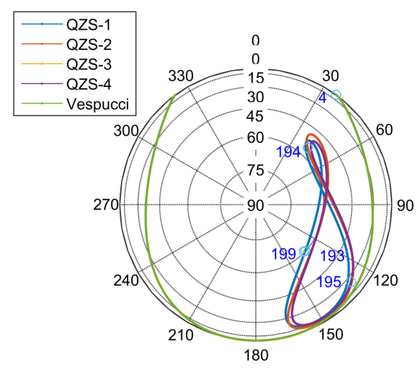
The skyplot for a user in Xi’an (34°8′ N, 108°59′ E), China is shown in Figure 6. In Xi’an, the elevations of QZS-1, QZS-2, QZS-4 are sometimes less than 10 degrees or even invisible. The elevation of each satellite is greater than 10 degrees for some duration, which is approximately 18 h. Meanwhile, QZS-3 is always at about 46 degrees. Vespucci has a total of 8 h of elevation above 10 degrees for two periods. The trend of the elevation of Vespucci is always opposite to that of a satellite in QZSS. It should be noted that the SDR cannot use the constellation with less than four visible satellites for positioning measurement.
The signal collection site is located on the 1st-floor roof of the National Time Service Center (NTSC) of the Chinese Academy of Sciences. The position where the omnidirectional antenna was placed is shown in Figure 7. Although only four satellites are visible in Xi’an, they can be used to verify the optimization of joint positioning on GPS III + QZSS constellations.
Since Sanya is in southern China, the elevation of satellites of QZSS and Vespucci of GPS III are several degrees higher than those of Xi’an. The skyplot for a user in Sanya (18°18′ N, 109°15′ E), China observing GPS III and QZSS orbits is shown in Figure 8. At Sanya, the satellites of QZSS is always visible and always significantly above 10 degrees elevation. Vespucci of GPS III is greater than 0 degrees about 12 h. As shown in Figure 8, most of the dwell time, QZSS is at high elevation that greater than 45 degrees (~15 h). But the trend of the elevation of Vespucci is always opposite to that of a satellite in QZSS, which is the same as in the Xi’an constellation. The signal collected in Sanya also using the test equipment. If the constellation contains satellites with an elevation below 10 degrees, the positioning results will get tremendous deterioration [38]. So satellites collected below 10 degrees should be avoided.
The location at the hotel building by the sea was used for the signal collection. To receive GPS III and QZSS satellites signals, an omnidirectional antenna was placed on the third-floor balcony, as shown in Figure 9. We analyze the signal collected in Sanya at UTC 12:08:10, 13 April 2019. The skyplot of the satellites visible in the course of the signal collection is shown in Figure 10. As seen in the skyplot, GPS III and QZSS satellites are at high elevation and their direct signals could be visible at the balcony location.

4. Results and Discussion

In this section, we give the carrier-to-noise ratio of the L1C signal. We used the data collected in Sanya to investigate the ranging difference of the two components of the L1C signal at different correlation spacing. Next, we verify the performance of the joint positioning of GNSS Receiver using the data collected in Xi’an. Under this premise, we investigate the position error of the two components of the L1C signal. It should be noted that the data length analyzed in this section is 60 s, which is enough to verify the performance of GNSS Receiver and the performance of the L1C signal.

4.1. C/N0 of L1C Observables

This section presents the noise characteristics of L1C observables based on the observed carrier-to-noise-density ratio (C/N0). The C/N0 was carried out using signal collected in Sanya, China. Figure 11 depicts the observed C/N0 of L1C signal transmitted on Vespucci which includes both L1CD and L1CP. The trends of C/N0 of L1CD and L1CP transmitted by the same satellite are identical. On L1C signal, the pilot occupies 75% of the signal power. So, the C/N0 of L1CP is more than L1CD approximately 5 dB. Hence, the L1CP has better tracking performance than L1CD, and the tracking results of L1CP are more accurate than L1CD considering the influence of noise. Moreover, the C/N0 of the enhanced signal transmitted by QZSS is greater than that of GPS III.

4.2. Performance of Ranging and Positioning

The signal collected in Sanya, China was processed off-line used GNSS Receiver to analyze the ranging difference. This signal yielded the most consistent results as to all five satellites are visible for a significant time. Respectively, Figure 12 and Figure 13 depict the ranging difference from 0.05 chips correlator spacing of L1CP transmitted by QZS-1 and Vespucci for several correlator spacing. The ranging difference is averaged by 2000 pseudorange samples. As expected, the ranging difference of L1CD using BOC(1,1) are similar for different correlator spacing and increases with correlator spacing. Nevertheless, the ranging difference of TMBOC(6,1,4/33) vary significantly with different correlator spacing. The worst ranging difference of L1CP using TMBOC(6,1,4/33) is 0.25 chips correlator spacing in various correlator spacing, followed by 0.2 chips and 0.3 chips.
As shown in Figure 14 and Figure 15, the ranging fluctuations of the difference of L1CP and L1CD transmitted by each satellite are calculated by (7). For Vespucci (green line), regardless of whether Gaussian noise is removed or not, the ranging difference of L1CP using 0.2 chips, 0.25 chips and 0.3 chips is worse than L1CD, but it is superior to L1CD using the other correlator spacing. This phenomenon is repeated in the other three QZSS satellites. But there is a downward trend from 0.125 chips to 0.15 chips, which indicates that multipath and interference affect the signal at 0.125 chips. By comparing the ranging difference, it is proved that the resistance to complex environments of TMBOC(6,1,4/33) outperforms that of BOC(1,1).
As shown in Figure 14, for QZS-1 (blue line), although both L1CD and L1CP use BOC (1,1) modulation, L1CP ranging is more accurate due to higher C/N0. However, after removing Gaussian noise in Figure 15, this phenomenon becomes less obvious. Referring to Table 1, it is worth noting that satellites with higher C/N0 produce a little difference in ranging for both BOC(1,1) and TMBOC(6,1,4/33). But after smoothing in Figure 15, the ranging difference of each satellite has been independent of the C/N0.
Since the constellation of GPS III is under development, the L1C signal transmitted by GPS III is merely available in the segment of the period. As a consequence of using joint positioning, the complementary effects between the constellations will be demonstrated using the signal collected in Xi’an. In order to illustrate the influence of the geometry of the satellite constellation, the positioning results of Xi’an are shown in the topocentric coordinate system. Succeedingly, the advantages of joint positioning using the L1C signal will be demonstrated using the signal collected in Sanya. In order to make a fair comparison, the same segment of the period is used in each comparison to ensure that the positioning results are in the same constellation geometry. However, the positioning error of Sanya is expressed in the WGS-84 coordinate system for the purpose of clearly comparing the error.
Table 2 lists tow periods of QZSS and GPS III satellites visible in Xi’an. With the elevation of QZS-1 reduced to almost 10 degrees, L1C of the QZSS-only can still be used for autonomous positioning at 8:34, as shown in Figure 16. It can be seen from the skyplot that the QZSS satellites are generally concentrated in the southeast direction of the observation site. Influenced by the geometric configuration of the constellation, the positioning error is gigantic in the east (E) direction. Soon after, GNSS Receiver using L1C signal lost its positioning ability because barely the remaining 3 satellites were visible in the QZSS-only constellation. GNSS Receiver using the GPS III + QZSS L1C joint positioning method restored the positioning capability at 11:02, although the PDOP value became worse than at 8:34, as shown in Figure 17. Since the satellites are generally concentrated at a higher elevation, the positioning results show a large deviation in the up (U) direction.
The signal collected in Sanya when five satellites are simultaneously visible is used to compare the positioning performance of GPS III + QZSS and QZSS-only. By use of the same correlator spacing (0.1 chips), the three-dimensional positioning error of TMBOC(6,1,4/33) and BOC(1,1) is given in Figure 18 and Figure 19, respectively using the constellations of GPS III + QZSS or QZSS-only. The positioning error is averaged by 2000 positioning samples. Whether using joint positioning or QZSS-only positioning, the positioning error of TMBOC(6,1,4/33) is generally superior to BOC(1,1) in three dimensions. At 15 s, the positioning performance of the signal is affected by the environment which may include multipath and signal distortion. It can be seen that TMBOC(6,1,4/33) shows better resistance at this time. Regardless of whether TMBOC(6,1,4/33) or BOC(1,1) is used, the positioning error of joint positioning is little than that of QZSS-only in three dimensions. This is the result of joint positioning optimizing the constellation composition while reducing the PDOP from 11.22 to 6.45. Since a priori position information cannot be obtained by GNSS Receiver, the position coordinates must be zeroed at the initial of regression, which results in a large positioning error in the initial stage.
The joint positioning error using 0.15 chips and 0.2 chips correlator spacing is shown in Figure 20 and Figure 21. The enormous ranging difference from Figure 13 of TMBOC(6,1,4/33) at 0.2 chips is reflected in the three-dimensional positioning error. In this case, the positioning error of TMBOC(6,1,4/33) deteriorates drastically compared to that of BOC(1,1), referring to Figure 20, and its resistance to interference is worse than BOC(1,1) at about 15 s.
The 0.175 chips spacing is selected here for clear contrast with other correlator spacing. Although the positioning error of TMBOC(6,1,4/33) also deteriorated at 0.175 chips, the positioning error at 0.4 chips was significantly restored, as shown in Figure 22. As shown in Figure 23, the positioning error increases with the correlator spacing for BOC (1,1). These phenomena agree with the variation of the ranging difference.

5. Conclusions

The transmission of the new navigation signal leads to the need to verify its performance in ranging and positioning. We propose a method for SDR to use L1C signal for ranging and joint positioning. The evaluation methodology is also proposed for the results using in-orbit signals. The comparison of ranging difference between BOC(1,1) and TMBOC(6,1,4/33) transmitted by GPS III and QZSS is given. The results from GPS III and QZSS demonstrate that the ranging performance of TMBOC(6,1,4/33) has better than BOC(1,1) but the choice of correlator spacing needs to be considered. The poor selection of correlator spacing will result in worse ranging performance for TMBOC(6,1,4/33).
The experiment of Xi’an adopted the L1C signal transmitted by the first GPS III satellite, Vespucci, to verify the positioning performance. The joint positioning results prove that the QZSS L1C signal has the claimed enhancement and supplement effect on GPS. We give a direct comparison of GPS III + QZSS joint positioning vs. QZSS-only using in-orbit signals collected in Sanya. Due to the optimization of the constellation configuration, the positioning error of joint positioning is reduced. Meanwhile, the positioning results using different correlator spacing verify that the ranging difference of TMBOC(6,1,4/33) caused by the poor correlator spacing will affect the positioning result. But properly selecting the correlator spacing allows the positioning performance of TMBOC(6,1,4/33) outperforms that of BOC(1,1).

Author Contributions

X.H. conceived and wrote the paper; X.W. supervised the paper and suggested modifications; S.W. and X.C. analyzed the data; G.Z. and X.L. collected the data. All authors have read and agreed to the published version of the manuscript.

Funding

This research received no external funding.

Conflicts of Interest

The authors declare no conflict of interest.

Appendix A

Table A1. Symbols in (1) and their meanings.
SymbolMeaning
c Speed of light in m/s
B L One-sided equivalent rectangular bandwidth of the code-tracking loop in Hz
T P Integration time used by the discriminator in seconds
B f Precorrelation filter bandwidth in Hz
G L ( f ) Power spectral density of the local reference signal in W/Hz
G L , R ( f ) Power spectral density of the received signal in W/Hz
d Correlator spacing in seconds
T c Pseudo-code period in seconds
C / N 0 Carrier-to-noise-density ratio in Hz
Table A2. Symbols in (2) and their meanings.
SymbolMeaning
Δ ρ n Pseudorange difference between the nth satellite and the reference satellite
t n Start time of the common frame of the nth satellite
Table A3. Symbols in (3) and their meanings.
SymbolMeaning
c Speed of light in m/s
δ t Clock error in seconds
r Tange in meters
I ρ Ionospheric error in meters
T ρ Tropospheric error in meters
ε ρ Receiver thermal noise error in meters
M P ρ Multipath error in meters
S D M ρ Nominal signal deformation in meters
Table A4. Symbols in (4) and their meanings.
SymbolMeaning
ρ n Ranging difference in meters
ρ n Pseudorange of the user receiver in meters
ρ r e f Pseudorange of the reference receiver in meters
ε ρ , n Correlator-spacing dependent error at user receiver in meters
ε ρ , r e f Correlator-spacing dependent error at the reference receiver in meters
M P ρ , n The multipath error at user receiver in meters
M P ρ , r e f Multipath error at the reference receiver in meters
S D M ρ , n Nominal signal deformation error at user receiver in meters
S D M ρ , r e f Nominal signal deformation error at the reference receiver in meters
Table A5. Symbols in (5) and (6) and their meanings.
SymbolMeaning
{ ρ n j , j = 1 , , M } A set of satellite pseudorange observed by the nth user receiver
( x n , y n , z n ) Three-dimensional coordinates of the nth user receiver
( x r e f , y r e f , z r e f ) Three-dimensional coordinates of the reference receiver
( x n , y n , z n ) Positioning error of the nth user receiver
Table A6. Symbols in (7) and their meanings.
SymbolMeaning
ρ Ranging difference or positioning error
n Length of ranging difference or positioning error

References

  1. Voosen, P. GPS Satellites Yield Space Weather Data. Science 2017, 355, 443. [Google Scholar] [CrossRef] [PubMed]
  2. Flynn, C.D.; McCaffrey, A.M.; Jayachandran, P.T.; Langley, R.B. Discovery of New Code Interference Phenomenon in GPS Observables. GPS Solut. 2019, 23, 65. [Google Scholar] [CrossRef]
  3. U.S. National Coordination Office for Space-Based Positioning Navigation and Timing. Global Positioning System Directorate Systems Engineering & Integration Interfaces Specification IS-GPS-200J NAVSTAR GPS Space Segment/Navigation User Segment Interfaces; U.S. National Coordination Office for Space-Based Positioning Navigation and Timing: Washington, DC, USA, 2018.
  4. Marques, H.A.S.; Monico, J.F.G.; Marques, H.A. Performance of the L2c Civil GPS Signal under Various Ionospheric Scintillation Effects. GPS Solut. 2016, 20, 139–149. [Google Scholar] [CrossRef] [Green Version]
  5. Nadarajah, N.; Khodabandeh, A.; Teunissen, P.J.G. Assessing the Irnss L5-Signal in Combination with GPS, Galileo, and QZSS L5/E5a-Signals for Positioning and Navigation. GPS Solut. 2016, 20, 289–297. [Google Scholar] [CrossRef]
  6. Hegarty, C.J.; Chatre, E. Evolution of the Global Navigation Satellitesystem (GNSS). Proc. IEEE 2008, 96, 1902–1917. [Google Scholar] [CrossRef]
  7. Shim, D.-S.; Jeon, J.-S. An Unambiguous Delay-and-Multiply Acquisition Scheme for GPS L1c Signals. Sensors 2018, 18, 1739. [Google Scholar] [CrossRef] [Green Version]
  8. Choy, S.; Harima, K.; Li, Y.; Choudhury, M.; Rizos, C.; Wakabayashi, Y.; Kogure, S. GPS Precise Point Positioning with the Japanese Quasi-Zenith Satellite System Lex Augmentation Corrections. J. Navig. 2015, 68, 769–783. [Google Scholar] [CrossRef] [Green Version]
  9. Namie, H.; Okamoto, O.; Kubo, N.; Yasuda, A. Initial Performance Evaluation of Centimeter-Class Augmentation System Using Quasi-Zenith Satellite System. Electron. Commun. Jpn. 2018, 101, 3–10. [Google Scholar] [CrossRef]
  10. Zaminpardaz, S.; Wang, K.; Teunissen, P.J.G. Australia-First High-Precision Positioning Results with New Japanese Qzss Regional Satellite System. GPS Solut. 2018, 22, 101. [Google Scholar] [CrossRef] [Green Version]
  11. Japan Aerospace Exploration Agency. Interface Specification for QZSS (IS-QZSS-PNT-002); Japan Aerospace Exploration Agency: Tokyo, Japan, 2018. [Google Scholar]
  12. U.S. National Coordination Office for Space-Based Positioning Navigation and Timing. Global Positioning System Directorate Systems Engineering & Integration Interfaces Specification IS-GPS-800E NAVSTAR GPS Space Segment/User Segment L1C Interface; U.S. National Coordination Office for Space-Based Positioning Navigation and Timing: Washington, DC, USA, 2018.
  13. Nguyen, D.T.; Park, Y. Performance Analysis of Interleaved LDPC for Optical Satellite Communications. Opt. Commun. 2019, 442, 13–18. [Google Scholar] [CrossRef]
  14. Suls, A.; Lefevre, Y.; Hecke, J.V.; Guenach, M.; Moeneclaey, M. Error Performance Prediction of Randomly Shortened and Punctured LDPC Codes. IEEE Commun. Lett. 2019, 23, 560–563. [Google Scholar] [CrossRef]
  15. Rushanan, J.J. The Spreading and Overlay Codes for the L1c Signal. Navigation 2007, 54, 43–51. [Google Scholar] [CrossRef]
  16. Sun, C.; Zhao, H.; Feng, W.; Du, S. A Frequency-Domain Multipath Parameter Estimation and Mitigation Method for Boc-Modulated GNSS Signals. Sensors 2018, 18, 721. [Google Scholar]
  17. Yan, T.; Wei, J.; Tang, Z.; Qu, B.; Zhou, Z. Unambiguous Combined Correlation Functions for Sine-BOC Signal Tracking. GPS Solut. 2015, 19, 623–638. [Google Scholar] [CrossRef]
  18. Chen, Y.H.; Lo, S.; Enge, P.; Akos, D. Direct Comparison of the Multipath Performance of L1 BOC and L1 C/A Using On-Air Galileo and Quasi-Zenith Satellite System (QZSS) Transmissions. In Proceedings of the 2014 IEEE/ION Position, Location and Navigation Symposium—PLANS 2014, Monterey, CA, USA, 5–8 May 2014; pp. 823–832. [Google Scholar]
  19. Lee, C.; Chen, Y.-H.; Wong, G.; Lo, S.; Enge, P. Multipath Benefits of BOC vs. BPSK Modulated Signals Using On-Air Measurements. In Proceedings of the 2013 International Technical Meeting of The Institute of Navigation, San Diego, CA, USA, 27–29 January 2013; pp. 742–751. [Google Scholar]
  20. Wang, K.; Chen, P.; Zaminpardaz, S.; Teunissen, P.J.G. Precise Regional L5 Positioning with IRNSS and QZSS: Stand-Alone and Combined. GPS Solut. 2018, 23, 10. [Google Scholar] [CrossRef] [Green Version]
  21. Kuzin, S.; Mitrikas, V.; Revnivykh, S.; Tatevyan, S. On the Role of Glonass for the Development of the Russian Geodetic Reference Network. Artif. Satell. 2007, 42, 113–120. [Google Scholar]
  22. Soycan, M. A Quality Evaluation of Precise Point Positioning within the Bernese GPS Software Version 5.0. Arab. J. Sci. Eng. 2012, 37, 147–162. [Google Scholar] [CrossRef]
  23. Nistor, S.; Buda, A. High Rate 30 Seconds Vs Clock Interpolation in Precise Point Positioning (PPP). Geod. Vestn. 2016, 60, 483–494. [Google Scholar] [CrossRef]
  24. Rabah, M.; Elmewafey, M.; Farahan, M.H. Datum Maintenance of the Main Egyptian Geodetic Control Networks by Utilizing Precise Point Positioning “PPP” Technique. NRIAG J. Astron. Geophys. 2016, 5, 96–105. [Google Scholar] [CrossRef]
  25. Maciuk, K. GPS-Only, GLONASS-Only and Combined GPS+GLONASS Absolute Positioning under Different Sky View Conditions. Tehnički Vjesnik 2018, 25, 933–939. [Google Scholar]
  26. Ashraf, F. Variation of Static-PPP Positioning Accuracy Using GPS-Single Frequency Observations (Aswan, Egypt). Artif. Satell. 2017, 52, 19–26. [Google Scholar]
  27. Liu, L.; Amin, M.G. Performance Analysis of GPS Receivers in Non-Gaussian Noise Incorporating Precorrelation Filter and Sampling Rate. IEEE Trans. Signal Process. 2008, 56, 990–1004. [Google Scholar] [CrossRef]
  28. Borre, K. The GPS Easy Suite–MATLAB Code for the GPS Newcomer. GPS Solut. 2003, 7, 47–51. [Google Scholar] [CrossRef]
  29. Fine, P.; Wilson, W. Tracking Algorithm for GPS Offset Carrier Signals. In Proceedings of the 1999 National Technical Meeting of the Institute of Navigation, San Diego, CA, USA, 25–27 January 1999; pp. 671–676. [Google Scholar]
  30. Betz, J.; Blanco, M.A.; Cahn, C.R.; Dafesh, P.A.; Hegarty, C.J.; Hudnut, K.W.; Kasemsri, V.; Keegan, R.; Kovach, K.; Lenahan, L.S.; et al. Description of the L1C Signal. In Proceedings of the 19th International Technical Meeting of the Satellite Division of the Institute of Navigation (ION GNSS 2006), Fort Worth, TX, USA, 26–29 September 2006; pp. 2080–2091. [Google Scholar]
  31. Progri, I.F.; Bromberg, M.C.; Michalson, W.R.; Wang, J. A Theoretical Survey of the Spreading Modulation of the New GPS Signals (L1C, L2C, and L5). In Proceedings of the 2007 National Technical Meeting of the Institute of Navigation, San Diego, CA, USA, 22–24 January 2007; pp. 561–569. [Google Scholar]
  32. Julien, O.; Macabiau, C.; Issler, J.-L.; Ries, L. 1-Bit Processing of Composite BOC (CBOC) Signals and Extension to Time-Multiplexed BOC (TMBOC) Signals. In Proceedings of the 2007 National Technical Meeting of The Institute of Navigation, San Diego, CA, USA, 22–24 January 2007; pp. 227–239. [Google Scholar]
  33. Mattos, P.G.; Pisoni, F. GPS-III L1C Signal Reception Demonstrated on QZSS. In Proceedings of the 2012 IEEE/ION Position, Location and Navigation Symposium, Myrtle Beach, SC, USA, 23–26 April 2012; pp. 1162–1168. [Google Scholar]
  34. Betz, J.W.; Kolodziejski, K.R. Generalized Theory of Code Tracking with an Early-Late Discriminator Part I: Lower Bound and Coherent Processing. IEEE Trans. Aerosp. Electron. Syst. 2009, 45, 1538–1556. [Google Scholar] [CrossRef]
  35. Betz, J.W.; Kolodziejski, K.R. Generalized Theory of Code Tracking with an Early-Late Discriminator Part II: Noncoherent Processing and Numerical Results. IEEE Trans. Aerosp. Electron. Syst. 2009, 45, 1557–1564. [Google Scholar] [CrossRef]
  36. Wong, G.; Chen, Y.-H.; Phelts, R.E.; Walter, T.; Enge, P. Measuring Code-Phase Differences due to Inter-Satellite Hardware Differences. In Proceedings of the 25th International Technical Meeting of the Satellite Division of The Institute of Navigation (ION GNSS 2012), Nashville, TN, USA, 17–21 September 2012; pp. 2150–2158. [Google Scholar]
  37. De Bakker, P.F.; Tiberius, C.C.J.M.; van der Marel, H.; van Bree, R.J.P. Short and Zero Baseline Analysis of GPS L1 C/A, L5Q, GIOVE E1B, and E5aQ Signals. GPS Solut. 2012, 16, 53–64. [Google Scholar] [CrossRef] [Green Version]
  38. Wang, K.; Chen, P.; Teunissen, J.P. Single-Epoch, Single-Frequency Multi-GNSS L5 RTK under High-Elevation Masking. Sensors 2019, 19, 1066. [Google Scholar] [CrossRef] [Green Version]
Figure 1. The test equipment for collecting signals.
Electronics 09 00011 g001
Figure 2. Flow chart of DLL (Bump-Jump) and PLL used by tracking algorithm in the GNSS Receiver.
Electronics 09 00011 g002
Figure 3. Flow chart of the ranging and positioning after tracking algorithm.
Electronics 09 00011 g003
Figure 4. Autocorrelation Function for TMBOC(6,1,4/33) and BOC(1,1).
Electronics 09 00011 g004
Figure 5. Code-tracking error with different correlator spacing. (a) Overall view; (b) Close-up view.
Electronics 09 00011 g005aElectronics 09 00011 g005b
Figure 6. Skyplot of GPS III and QZSS satellites with L1C observed at Xi’an (34°8′ N, 108°59′ E), China, on 25 January 2019, with 0° elevation cutoff.
Electronics 09 00011 g006
Figure 7. Signal collection site at NTSC roof.
Electronics 09 00011 g007
Figure 8. Skyplot of GPS III and QZSS satellites with L1C observed at Sanya (18°18′ N, 109°15′ E), China, on 13 April 2019, with 0° elevation cutoff.
Electronics 09 00011 g008
Figure 9. Signal collection site at the hotel balcony.
Electronics 09 00011 g009
Figure 10. Skyplot of satellites visible during GPS III + QZSS signal collection (PRN number is shown).
Electronics 09 00011 g010
Figure 11. Carrier-to-noise-density ratio (C/N0) of L1C transmitting on Vespucci tracked by GNSS Receiver.
Electronics 09 00011 g011
Figure 12. Ranging difference from reference 0.05 chips spacing for QZS-1 L1CP (BOC).
Electronics 09 00011 g012
Figure 13. Ranging difference from reference 0.05 chips spacing for Vespucci L1CP (TMBOC).
Electronics 09 00011 g013
Figure 14. Ranging difference of L1CD (solid line) and L1CP (dashed line) transmitted in each satellite with different correlator spacing without smoothing.
Electronics 09 00011 g014
Figure 15. Ranging difference of L1CD (solid line) and L1CP (dashed line) transmitted in each satellite with different correlator spacing after smoothing.
Electronics 09 00011 g015
Figure 16. Positioning results of data collected in Xi’an at 8:34:28 (PDOP = 9.604). (a) Skyplot; (b) Variation in East (E), North (N) and Up (U); (c) Positioning result in the 3D map.
Electronics 09 00011 g016
Figure 17. Positioning results of data collected in Xi’an at 11:02:33 (PDOP = 13.848). (a) Skyplot; (b) Variation in East (E), North (N) and Up (U); (c) Positioning result in the 3D map.
Electronics 09 00011 g017
Figure 18. Position error from GPS III + QZSS (PDOP = 6.45, correlator spacing = 0.1 chips).
Electronics 09 00011 g018
Figure 19. Position error from QZSS-only (PDOP = 11.22, correlator spacing = 0.1 chips).
Electronics 09 00011 g019
Figure 20. Position error from GPS III + QZSS (correlator spacing = 0.15 chips).
Electronics 09 00011 g020
Figure 21. Position error from GPS III + QZSS (correlator spacing = 0.2 chips).
Electronics 09 00011 g021
Figure 22. Position error from L1CP when using different correlator spacing.
Electronics 09 00011 g022
Figure 23. Position error from L1CD when using different correlator spacing.
Electronics 09 00011 g023
Table 1. Average C/N0 of each satellite in 1 min (dB-Hz).
Component of L1CQZS-1QZS-2QZS-3QZS-4Vespucci
L1CD44.943.441.445.240.3
L1CP49.948.846.550.845.5
Table 2. Satellites visibility during two acquisition periods on January 25 2019.
Period (UTC)VisibleInvisible
8:34:28–8:35:28QZS-1, QZS-2, QZS-3, QZS-4Vespucci
11:02:33–11:03:33QZS-2, QZS-3, QZS-4, VespucciQZS-1

