Article

Smart Public Lighting Control and Measurement System Using LoRa Network

by
F. Sánchez Sutil
* and
Antonio Cano-Ortega
*
Department of Electrical Engineering, University of Jaen, 23071 EPS Jaen, Spain
*
Authors to whom correspondence should be addressed.
Electronics 2020, 9(1), 124; https://doi.org/10.3390/electronics9010124
Submission received: 12 December 2019 / Revised: 29 December 2019 / Accepted: 7 January 2020 / Published: 9 January 2020
(This article belongs to the Special Issue IoT and Its Applications in Electric Energy Systems)

Abstract

:
The installation of smart meters in smart cities to monitor streetlights (SLs) provides easy access to measurements of electrical variables and lighting levels, which improves the operation of installation. The use of smart meters in cities requires temporary high-resolution data to improve the energy efficiency (EE) of SLs. Long range (LoRa) is an ideal wireless protocol for use in smart cities due to its low energy consumption, secure communications, and long range indoors and outdoors. For this purpose, we developed a low-cost new system and successfully evaluated it by developing three devices, namely the measure and control device for street lights (MCDSL), lighting level measurement device (LLMD) and gateway LoRa network (GWLN), based on the Arduino open-source electronic platform. This paper describes the hardware and software design and its implementation. Further, an algorithm has been developed to enhance the energy efficiency of public lights using MCDSL, the energy efficiency for street lights (EESL) algorithm, that use the illumination level measured on the same set of SLs with a dynamic control, which assumed different lighting levels throughout the night, and adjusted luminous flux based on the traffic intensity of pedestrians. It sends the acquired data through the LoRa low-power wide-area-network (LPWAN) to the cloud.

1. Introduction

Nowadays, the energy crisis and environment pollution have become a global problem, and the increasing use of energy has caused climate change. In order to minimize electricity consumption, new technology has to be implemented for street lighting systems. This energy consumption can be reduced considerably by applying new communication and control technologies. Power is required for most of the services to be implemented in smart cities, among which street lighting demands higher power consumption.
Kabalci et al. [1] presented the smart infrastructure system that includes a smart energy system as well as smart communication and smart information systems. In this way, the paper [2] provided a classification of technical and regulatory characteristics of IoT services for smart cities which are mapped to corresponding roles in the IoT value chain, and characterize and identify specific requirements for several smart city services, namely, smart metering, smart parking, smart street lighting and MCS.
In order to make the environment safe, its illumination has to comply with lighting norms, and in this context, a comparative study of differences in energy consumption while applying 2004 and 2014 releases of the CEN/TR 13201 standard for lighting designs was analysed in [3]. Also, Ref. [4] offered a set of the most important recommendations regarding the relevant influencing factors for energy savings in street lighting.
Furthermore, Sedziwy et al. [5] allows obtaining power saving not only by replacing high pressure lamps with LEDs, but also by improving a design quality and by introducing a dynamic street lighting control. In addition to the paper [6] the authors improved the energy efficiency and quality of street lighting by applying two different solutions to achieve energy saving in street lighting design: the installation of luminous flux regulators and the replacement of existing luminaires with LED. Also, a study has been done to analyse the different devices which influence energy consumption with the intention of better understanding their behaviour and performance in [7], in which the authors improve the effectiveness of these regulations and therefore to optimize energy consumption.
Carli et al. [8] studied a multi-criteria decision-making tool to support the public decision maker in optimizing energy retrofit interventions on existing public street lighting systems. Further, a method of determining the power losses occurring in a lighting system, depending on the power supply conditions and the dimming level is described in [9], wherein the authors determined that loss is dependent on the configuration of the supply network, that is, whether it is single-phase or three-phase. The paper [10] focused on providing a formal basis to incorporate knowledge regarding multiple sensors into the lighting control model by introducing the dual graph grammar concept.
On the other hand, the hybrid poles group based on renewable energy, street lighting, and EV charging, which can realize fast charging and slow charging based on DC micro-grid with help of energy storage device is proposed in [11].
The bibliographical revision realized for the energy efficiency of SLs with wireless technologies has been elaborated on the basis of the measured parameters, wireless technology, sensors, and the base platform. Table 1 shows the results of the review:
LPWAN is a generic term for a group of technologies that enable wide area communications at lower cost points and better power consumption are developed in [28,29]. LoRa is particularly interesting due to the openness of its higher layer specifications LoRaWAN, and for the wide availability of low-cost devices. LoRa in [30] was also the only technology allowing construction of private LPWAN networks. As described in the research [28], the last years have seen the widespread diffusion of novel LPWAN technologies, which are gaining momentum and commercial interest, as technologies for the Internet of Things (IoT) are enabled. Finally, the paper [31] discussed some of the most interesting LPWAN solutions, focusing in particular on LoRa, one of the last born and most promising technologies for the wide-area IoT.
There are some applications about LoRa such as in the research [32] studied the concept of a vision system that monitors sag and temperature of overhead transmission lines using LoRa wireless communication and data transmission, the developed system consists of a camera and a microcomputer equipped with LoRa communication module. Also, in the paper [33] presented the development of relays that communicate with each other using LoRa allows for the combination of the cost-effectiveness and ease of installation of wireless networks with long-range coverage and reliability. In this way, Paredes-Parra et al. [34] proposed a wireless low-cost solution based on LoRa technology able to communicate with remote PV power plants, covering long distances with minimum power consumption and maintenance. Finally, the paper [35] presented a LoRa network for monitoring and enhancing of efficient energy of inductions motors.
In the literature reviewed, most authors do not design measuring devices for use in street lighting, instead, they use commercially available equipment already designed, and the transmission network has not been analysed. Therefore, in this work the authors have designed a measurement system for public lighting that allows to improve the energy efficiency of the SLs by means of monitoring and control equipment. In addition, the LoRa network has been designed to obtain the measured data in real time, to optimize the installation by means of a developed algorithm. This system allows to reduce the energy consumption of the campus.
In this paper, the authors propose a system to improve the efficient energy of SL using algorithm developed. Therefore, the authors present a number of novel contributions from our previous work and the state-of-the-art:
-
Design of our own system to improve energy efficiency in public lighting. Three device, namely the MCDSL, LLMD, and GWLN, have been developed.
-
These devices are low cost and open source, and were evaluated successfully.
-
Monitoring and control of a public lighting system using the EESL algorithm implemented in MCDSL, with communication via a LoRa network controlled by GWLN.
This paper is structured as follows. Section 2 presents the diverse requirements of street lighting from different road users’ perspectives and describes the LoRa network used. Subsequently, Section 3 presents the details of MCDSL, LLMD, and GWLN systems to manage SLs and minimise energy consumption using the EESL algorithm. Section 4 details the lamp tests done, and parameters adopted in this paper, and also presents the performance of the proposed lighting scheme in terms of the achieved SLs utility and consumed energy.

2. Theory Description

2.1. System Requirements

The main requirement to be taken into account in the design of the lighting of the proposed system is the fulfilment of mandatory standards defined for various areas such as streets, sidewalks, users, etc. For each of them, an appropriate lighting class is assigned according to the characteristics of the traffic: types of users, traffic intensity, average speed, etc.
The European standard EN 13201-1 [36] and Table 2 of the European standard EN 13201-2 [37] shows lighting classes for pedestrians and cyclists that set lighting levels for pedestrians use.
The proposed system takes into account the level of lighting required at any given moment, which is modified if pedestrians are present. Figure 1 shows the scheme of the system developed in this research.

2.2. LoRa Network

LoRa LPWAN networks composed of end-device, gateway device, and network server are organized in a star topology. End-devices send data to gateways over a single wireless hop and gateways relay messages to/from central network servers through a non-LoRa LPWAN network. Noreen et al. [38] provides in depth analysis of the impact of these three parameters on the data rate and time on air, and the paper [39] offers an in-depth analysis and assessment of LoRa LPWAN functional components: its capabilities (total traffic load, packet delivery quality) versus its efficiency (collision and frequency usage).
The LoRa radio has different configuration parameters: the carrier frequency (CF), spreading factor (SF), bandwidth (BW) and code rate (CR) [40,41,42,43]. The combination of these parameters provides different energy values and transmission ranges:
  • CF is the centre frequency used for the transmission band. For the SX1276/SX1276 transceiver, and is in the range of 433 MHz in Asia, 868 MHz in Europe, and 915 MHz in North America.
  • SF provides a trade-off between data rate and range. The choice of higher spreading factor can increase the range but decreases the data rate and vice versa. LoRa employs multiple orthogonal spreading factors (between 7 to 12).
  • BW: Transmitter sends the widespread data at a chip rate equal to the system bandwidth in chips per-second-per-Hertz. LoRa can only be chosen among three options: 125, 250, or 500 kHz.
  • CR: Forward error correction (FEC) techniques are used in Lora to further increase the receiver sensitivity. Code rate defines the amount of FEC. The coding rate expression is CR = 4 4 + n , n is from 1 to 4. It denotes that every four useful bits are encoded by 5, 6, 7, or 8 transmission bits.
The nominal bit-rate (in bits per second), is obtained taking into account these parameters. Moreover, the expression of the bit-rate is given in Equation (1):
R b   =   SF × B W 2 S F × C R
For LoRa, the actual time on the air for a packet can be defined as the duration of uplink and downlink transmissions. Further, tpk depends on parameters of LoRa modulation, such as SF, BW, CR, and can be expressed as the sum of the time needed to transmit the preamble and the physical message.
t p k = t p + t P H Y
Equations (3) and (4) represent how these two terms have been calculated, where Np is the number of symbols used by the radio transceiver as the physical preamble of the message and NPHY indicates the number of symbols transmitted in the physical message and can be determined as shown in Equation (6). Equation (5) defines tsym as the duration (in seconds) of a symbol which depends on SF and BW:
t p = t s y m × N p + 4.25
t P H Y = t s y m × N P H Y
t s y m = 2 S F B W
N P H Y = 8 + m a x [ c e i l ( 28 + 8 × P L + 16 × C R C 4 × S F 4 × ( S F 2 × D E ) ) × ( C R + 4 ) ,   0 ]
To calculate the time on air (or packet duration), first calculate the payload symbol. For a given payload denoted by PL (in bytes), a spreading factor (SF) and a coding rate (CR), the number of symbols NPHY used to transmit the payload can be calculated. CRC (cyclic redundancy check) indicates the presence (value 1) or not (value 0) of the CRC field in the physical message and DE indicates if the mechanism to prevent issues about the clock drift of the crystal reference oscillator is used (value 1 for SF12 and SF11, 0 for others).

2.3. EESL Algorithm

The algorithm has two paths: (i) hourly regulation; (ii) regulation by adaptation to the illumination level. Each of them has a different function in relation to time and pedestrian flow. The goal is to achieve the best adjustment of the luminous flux of the lamp, and therefore the optimization of electricity consumption. Thus, the algorithm dynamically adapts the luminous flux to the necessary conditions, so that the lamp does not always operate at 100% of the luminous flux.
The total energy saved Esav is given by:
E s a v = i = 1 n ( P b ( i ) × h b ( i ) P r ( i ) × h p e ( i ) )
where n is the number of lamps, Pb the total installed power in the baseline scenario in kW, hb the number of operating hours in the baseline scenario, Pr the reduced power in kW, and hpe the number of equivalent operating hours.
The regulation percentage %Reg is given by the following Equation (8)
% R e g ( t ) = ( R e g m a x L c u r ( t ) L m i n ( t ) L t h r e ( t ) L m i n ( t ) ) × 100
where Lcur is the current level, Lmax the maximum level, Lmin the minimum level, Lthre the threshold level, and Regmax is the maximum regulation allowed by the lamp.

3. Street Lights System Design

3.1. Hardware

This research approaches from zero the design and development of a SL control system to be used in a smart city with communication based on LoRa protocol and data storage in the cloud.
The system consists of three devices: (i) GWLN (gateway to LoRa network) to centralize communications and upload data to the cloud; (ii) MCDSL to control the SLs, make measurements of electrical variables and position with GPS, communicating through LoRa LPWAN with the GWLN; (iii) LLMD (light level measure device) to measure the lighting level and send the data to the GWLN.

3.1.1. GWLN Design

The core of the GWLN (Figure 2) is the AUR3 board [44] microcontroller on which DLS (Dragino LoRa shield) [45] version without GPS (global positioning system) is assembled, that centralizes communications under the LoRa protocol. The modular design allows the GWLN to be scalable and easy to replace components when one of them fails, so that it does not affect the operation of the equipment.
Figure 2 shows the GWLN block diagram and the relationship between the components used and the other components of the lighting system.
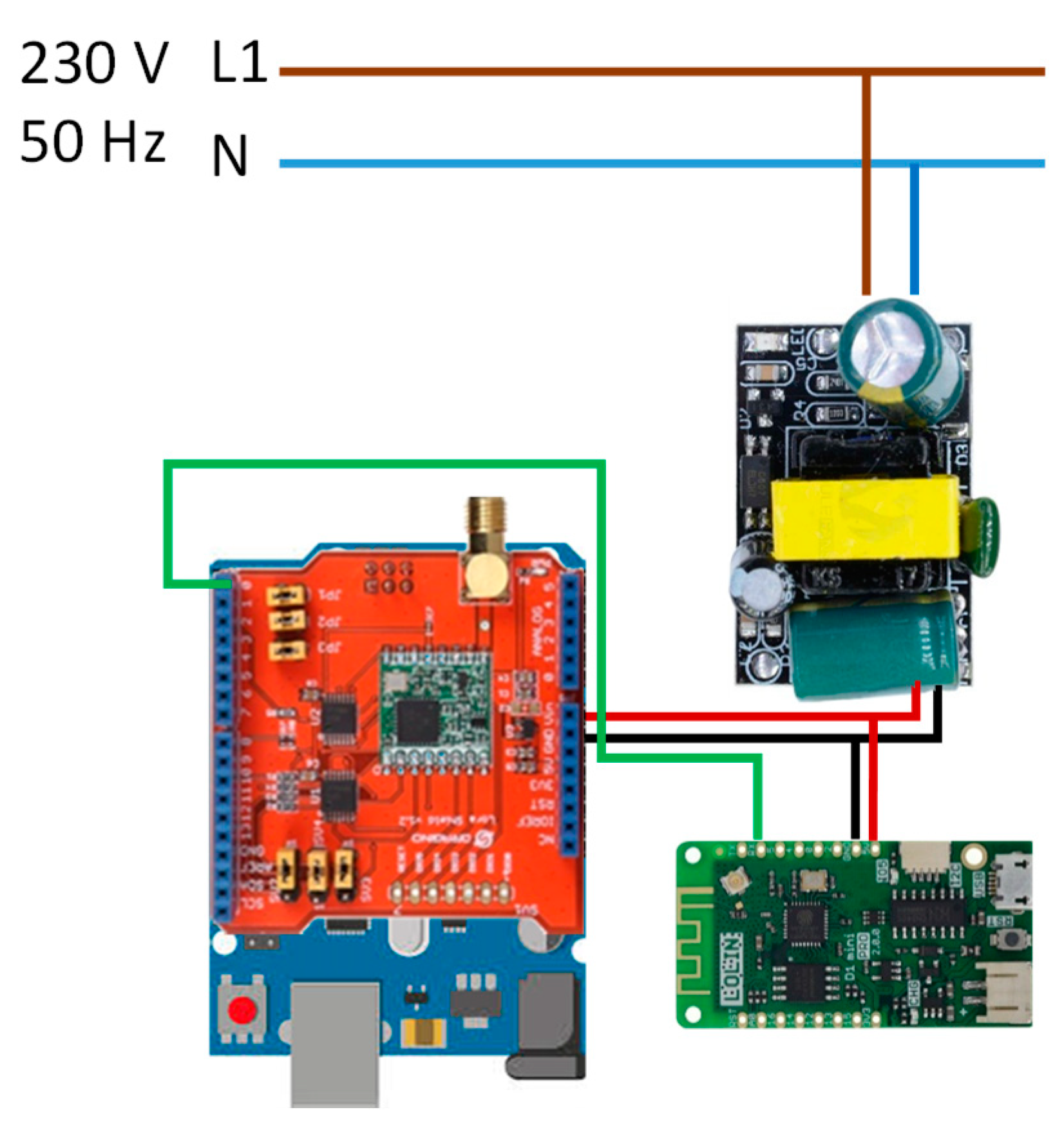
GWLN uses the serial port to perform programming with the computer. Once programmed, the serial port serves as a communication with WMP [46] board for uploading data to the cloud. DLS acts as GW (Gateway) for the LoRa system composed of MCDSL#1 … MCDSL#n and LLMD, all these components compose the LoRa LPWAN network used in this research. GWLN is powered by a power supply unit connected to the 230 V AC electrical network with 5 V DC output accepted by the AUR3 and WMP boards. Figure 3 shows the wiring diagram for GWLN.
Table 3 shows the cost of the components used in GWLN, and as can be seen it is a very small, very interesting feature for SL implementation in smart city.

3.1.2. MCDSL Design

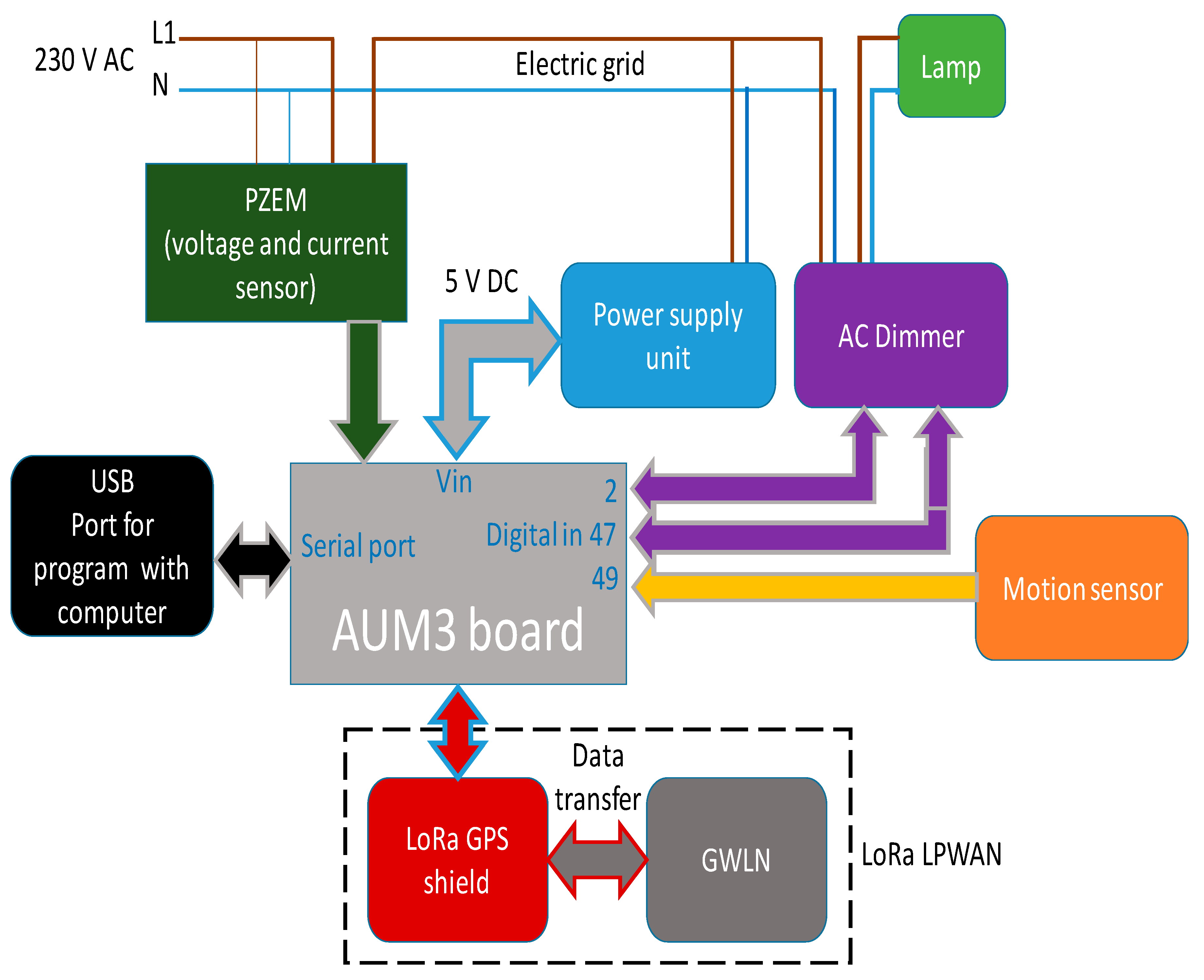
It is very useful to locate the SLs using GPS. Thus, in the design of MCDSL (Figure 4) the DLGS (Dragino LoRa GPS Shield) [47] has been used, which, in addition to the LoRa features, adds global positioning.
DLGS uses most of the AUR3 digital outputs for its operation and the GPS position is read by means of a serial port, in addition it makes incompatible the reading of the electric variable meter PZEM-004t (PZEM) [48] with digital inputs and it is necessary to use a serial port for its reading. From the above, it follows that at least two serial ports are needed in MCDSL. AUR3 only has one, so it is necessary to use AMR3 [49] as a microcontroller that has four serial ports.
The design of MCDSL is modular, as with GWLN, to provide fault tolerance, and to affect as little as possible the operation of the equipment. The MCDSL block diagram, together with the relationship between the components used and the LoRa LPWAN network are shown in Figure 4.
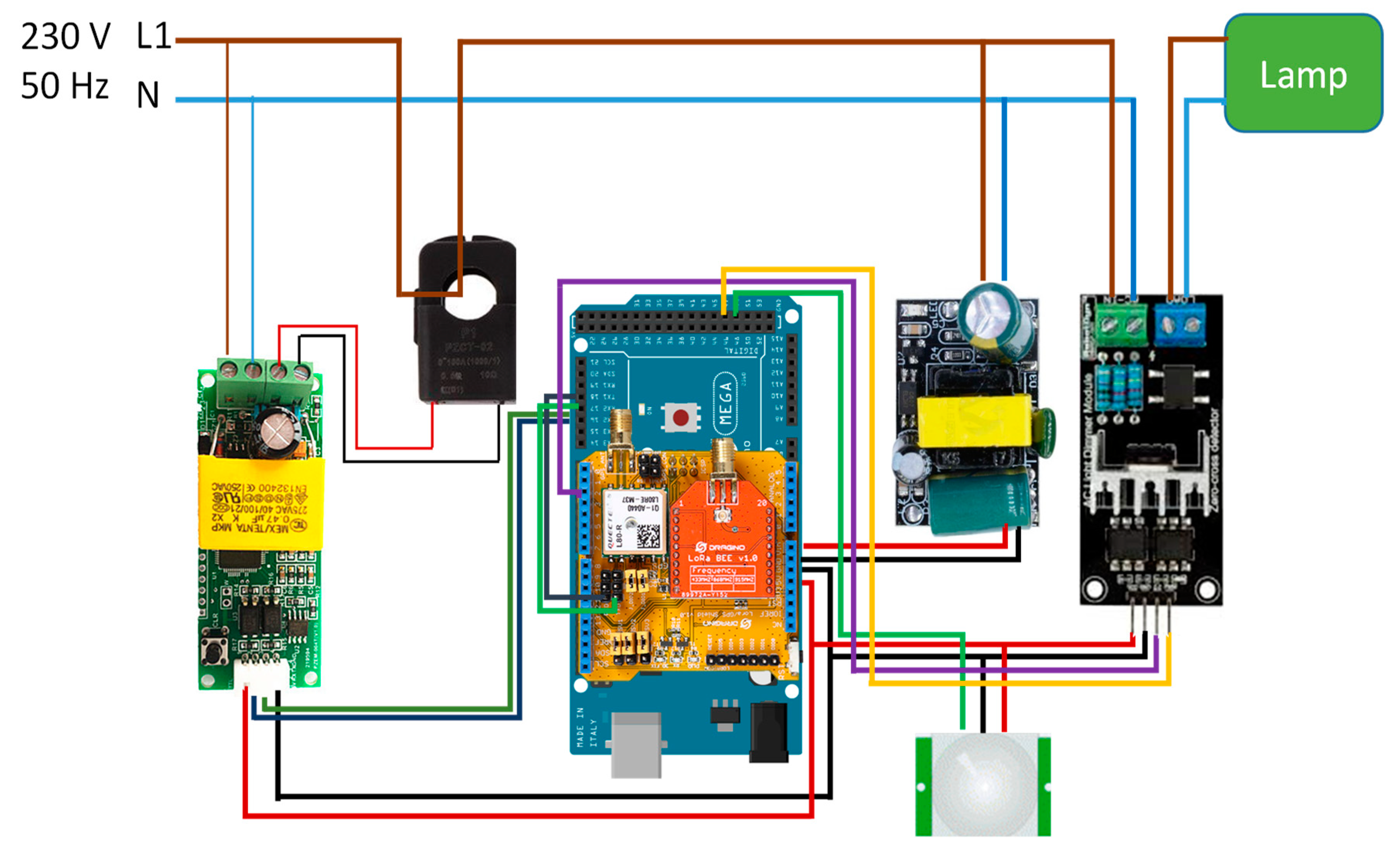
The distribution of AMR3 ports and signals for MCDSL is: (i) Serial1 port has been assigned the function of reading position data with GPS; (ii) serial2 performs the function of acquiring electrical variables v, i and p from the PZEM sensor; (iii) digital inputs 2 and 47 perform the task of communication with the AC Dimmer [50]; (iv) digital input 49 reads the data from the motion sensor to detect the presence of people. Figure 5 shows the wiring diagram for GWLN.
Table 4 shows the cost of the components used in GWLN, which is very small, and is especially interesting to use in the SL system in a smart city.

3.1.3. LLMD Design

To measure the level of illumination in each SL would lead to error, since when being placed in each one of them, mistakes can be made due to the fact that it would take the illumination that this providing the lamp and not the one that really there is in every moment.
For this purpose, a device has been designed that measures the actual level of illumination at a high point without being affected by the light from the lamps and provides a real measure of the illumination to be provided by the SL. The measurement times is 1 s. In case of a change in the lighting level, the measurement made by the LLMD (Figure 6) is sent by the LoRa LPWAN network to the GWLN. GWLN performs the necessary calculations by applying the EESL algorithm. It then sends the new regulation obtained to each of the SLs installed in the network.
LLMD has been implemented based on AUR3 supplemented with DLS and a TSL2561 [51] lighting meter connected to the AUR3 I2C (Inter-Integrated Circuit) bus. As for GWLN and MCDSL, a modular design is carried out that makes it more tolerant to faults. The LLMD block diagram, along with the relationship between the components used and the LoRa LPWAN network are shown in Figure 6.
LLMD uses the serial port of AUR3 for computer programming. Analog inputs 4 and 5 are used to work with the I2C bus in AUR3, in the case of LLMD to read the illumination level measured by TSL2561. Figure 7 shows the wiring diagram for LLMD.
Table 5 shows the cost of components used in LLMD, which is very small, following the low-cost design philosophy that is intended to be achieved with the system object of this research.

3.1.4. Components

1. Microcontroller
A microcontroller is a small computer integrated into a simple integrated circuit, containing at least one processing core, plus memory, and programmable inputs/outputs for use with peripherals. Microcontrollers are widely used in the construction of equipment for industrial and residential environments due to their control and processing capabilities.
The advances made in electronic devices have made it possible to develop very powerful hardware equipment at a low cost, which makes them ideal for use in a multitude of devices such as those developed in this research.
In this paper, three microcontrollers have been used:
  • AUR3 in GWLN and LLMD: the AUR3 development board, used in GWLN and LLMD, is based on the ATmega328P microcontroller, equipped with an open-source platform for electronic prototypes. The characteristics of AUR3 board are presented in [44].
  • AMR3 in MCDSL: in MCDSL has been chosen as the core with the development board AMR3, which is based on the ATmega2560 microcontroller, which like ATmega328P has open-source platform for developing electronic prototypes. The characteristics of DLS can be seen in [49].
  • WMP in GWLN: cloud access GWLN uses WMP based on the ESP-8266X microcontroller that allows access to the Wi-Fi network. The microcontroller is compatible with the Arduino development environment, with the open-source possibilities it offers. The characteristics of DLS are available in [46].
GWLN and LLMD only use the serial port for programming, since GWLN takes care of all the control functions and data traffic of the LoRa LPWAN and LLMD network reads the lighting measurement data via the I2C bus, and it is possible to use AUR3. In contrast, MCDSL uses two serial ports, one to read the position data with GPS and the other to read the electrical variables coming from the PZEM sensor and it is necessary to use AMR3 which has up to four serial ports available.
2. Wireless communication access. LoRa Shield
In order to implement the LoRa LPWAN network of the SL control system developed in this research, there are different options, among which we can highlight: (i) Arduino MKR WAN 1300 [52]; (ii) Monteino [53]; (iii) Lopy4 [54]; (iv) Libelium [55]; (v) Dragino [56]. The LoRa components used in this equipment are:
  • (i) uses the CMWX1ZZABZ chip [57] of the Murata brand.
  • (ii) uses the HOPERF chip RFM95/96/97/98 [58].
  • (iii) and (v) implement the Semtech SX1276/SX1278 [59] chip.
  • (iv) is based on the SX1272 [60] chip of the Semtech brand.
The components used in each platform have similar features. Therefore, the decision to use one or another platform depends on the added values that each one of them offers. The system developed uses the Dragino platform, which works with the Arduino family, benefiting from the great versatility that Arduino offers thanks to the large number of devices that can complement the LoRa LPWAN network. In this research, components such as GPS positioning, reading of electrical variables, presence detection, and measurement of the lighting level have been added. As a complement, it is very easy to program with the Arduino development environment, and being an open source platform, the reproduction of the system developed is possible by any researcher.
The LoRa SX1276/SX1278 chip developed for use in professional network environments with installed sensors is the core of DLS. The sensors that can be integrated have different uses such as irrigation systems, intelligent cities and houses, intelligent meters and industrial automation, etc.
With DLS data can be sent over long distances with different transmission frequencies. An added advantage is the minimal energy consumption thanks to the use of the ultra-long range extended spectrum, coupled with a high immunity to interference. The characteristics of DLS are in [45].
3. Wireless communication access. LoRa GPS Shield
The chosen manufacturer (Dragino) produces another model of Arduino Shield with LoRa System, to which it adds a GPS global positioning system that allows georeferencing the monitored equipment, which gives the system an added feature to the system that provides great versatility.
DLGS, like DLS uses the SX1276/SX1278 chip, to which is added the GPS system based on the MTK MT3339 chip. DLGS features are exposed in [47].
4. Electric power meter
To measure voltage and current, there are different techniques available on the market, which use different measurement techniques.
As for current sensors, there are invasive and non-invasive, the first ones need to modify the installation they monitor. The measurement techniques used are current transformers and Hall effect sensors. Both techniques convert the electrical current into a voltage signal proportional to the measured current. Examples of current sensors are the ACS712 [61] which is invasive and the STC-013 [62] which is non-invasive and is manufactured by the YHDC brand.
Various techniques can be used to measure voltage: (i) 230/12 or 24 V transformer, AC/DC rectifier and voltage divider; (ii) 230/24 V transformer, AC/DC rectifier, and FZ0430 [63] meter; (iii) ZMPT101b [64] voltage transformer from 230 to 5 V.
For the sensors mentioned in the previous paragraphs, in order to obtain RMS values of v, i, p, q, and PF, it is necessary to perform the corresponding calculation process. The PZEM sensor, chosen in this investigation, measures v, i, and p in a single sensor and offers the measured RMS values without additional calculations. In the paper [65], the authors developed and successfully calibrated a new prototype for an accurate low-cost on-time single-phase power smart meter and is based on the Arduino open-source electronic platform. Another example of the use of smart meters is in Reference [66], which presents a PF compensation system using a TLBO algorithm for optimization.
5. Illumination sensor
There are several options on the market to use as a lighting meter in combination with the Arduino platform: (i) sensor BH1750 [67]; (ii) sensor TSL2561.
The TSL2561 has been chosen for installation in LLMD because it is an advanced digital lighting sensor with applications in a wide range of devices. The sensor is very accurate, and allows you to select different operating modes by changing the gain and timing, with measurement range from 0.1 … 40,000+ lux. The sensor is composed of two diodes, one for the infrared part of the spectrum and the other for the rest of the spectrum, allowing for the separate measurement of both areas of the light spectrum.
The communication between the sensor and the Arduino is via the I2C bus, and three different directions can be selected for the sensor, ensuring that it can work with other devices connected to the bus without causing addressing problems. The features of the TSL2561 can be found at [51].
6. AC light dimmer
The dimmer used is from RobotDyn brand, which can control equipment up to 600 V and 16 A. Lighting control can be used to control fans, pumps and so on.
Arduino interruptions are used to control the dimmer, which reduces the wiring between the dimmer and the microcontroller. The dimmer is based on the triac BTA16-600B [68], with optocoupler insulation. The characteristics of the dimmer can be seen in [50].
7. Motion sensor
The sensor used is the PIR (passive infrared) type, with two separate detector elements, the signal that activates the motion alarm is the differential signal between the two detectors. The HC-SR501 model with the PIR LHI778 [69] sensor controlled by the BISS0001 [70] integrated circuit was chosen as the sensor to be installed in MCDSL.
It is possible to select the motion detection range with openings between 90° and 110°, and distance ranges between 3 and 7 m. It can be installed on the floor, on the wall or on the roof according to the needs of the detection to be carried out. It uses two potentiometers and a bridge to adapt detection sensitivity, activation time and response to repetitive actions. In [71], the characteristics of the sensor can be consulted.

3.2. Software Design

3.2.1. GWLN Program

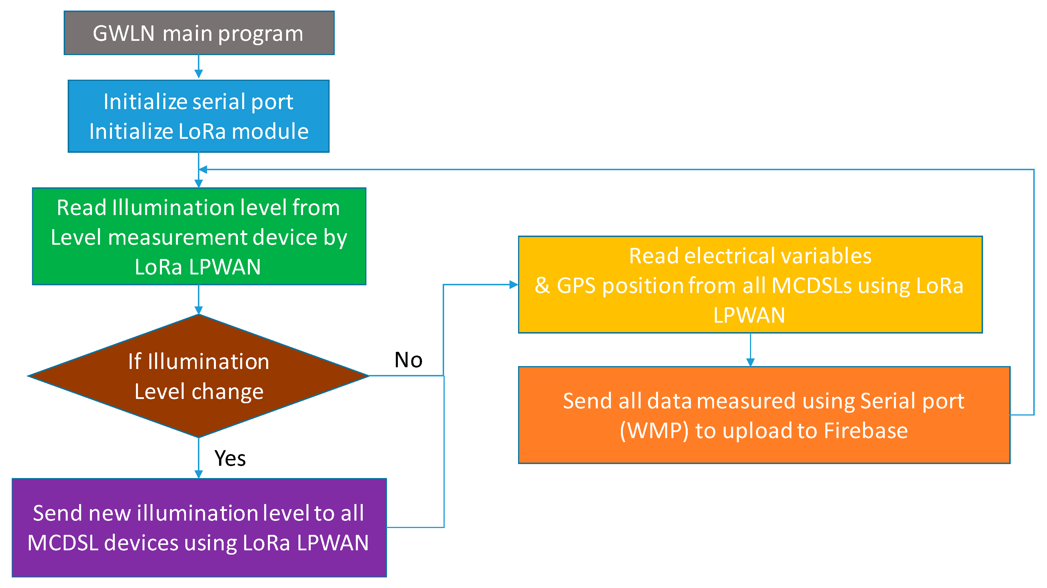
The AUR3 microcontroller manages the LoRa LPWAN network, receiving and sending information from LLMD and MCDSLs. It is also responsible for sending measurement data of electrical variables and GPS position to WMP to send to the cloud (Firebase).
The first working phase of the program is carried out when GWLN is connected, or a reset of the equipment is carried out. In this phase the following processes are developed: (i) enable and initialize the serial port for communications; (ii) configure and start the LoRa LPWAN network.
Once the first phase is done, the microcontroller must perform cyclically while the system is connected the reading of the lighting level from LLMD, if there is any change must send the information to all MCDSLs that are part of the LoRa LPWAN network, then must read the electrical variables and GPS position of all ESLs and send them to WMP for upload to the cloud (Firebase).
The flowchart for GWLN is shown in Figure 8.
Communication in the LoRa LPWAN network is bi-directional between GWLN, MCDSLs, and LLMD with a constant exchange of information between the teams involved in the network.

3.2.2. MCDSL Program

As the GWLN microcontroller, the MCDSL must perform the system initialization tasks when connecting or resetting the equipment. These tasks are distributed in the following sequence: (i) prepare the serial ports #1 and #2 to obtain data; (ii) start the PZEM sensor to measure electrical variables; (iii) turn on and prepare the AC dimmer for lamp regulation; (iv) start the HC-SR501 motion sensor; (v) configure and initialize DLGS for access to the LoRa LPWAN network.
Then, and continuously while MCDSL is connected, the following processes are carried out: (i) read the lighting level from the LoRa LPWAN network; (ii) run EESL algorithm; (iii) measure electrical variables and position with GPS and sending data to GWLN using the LoRa LPWAN network to upload to the cloud.
Figure 9 shows the flowchart for MCDSL.
The EESL algorithm proposed in this research and described in Section 2.3 has to be executed by MCDSL and adjust in real time the luminous flux that each lamp must emit according to the data of the level of illumination received in each instant from the LoRa LPWAN network, in addition to the detection of the presence of people through the motion sensor.
Figure 10 shows the flow diagram of the proposed EESL algorithm.

3.2.3. LLMD Program

The function of LLMD is to measure the lighting level for adjustment of all MCDSLs installed in the system. Therefore, the cyclic tasks you must perform once connected must be: (i) read the lighting level; (ii) send the measurement to GWLN using the LoRa LPWAN network.
As for the tasks of device initiation in case of connection or restart are: (i) configure and start DLS for access to the LoRa LPWAN network; (ii) initialize the TSL2561 lighting meter.
The LLMD flowchart is shown in Figure 11.

3.2.4. WMP Program

Finally, the program for WMP, which is responsible for uploading data to the cloud, is exposed. Remember that WMP is installed inside GWLN. The initialization tasks for this microcontroller are: (i) start the serial port for reading information from AUR3; (ii) configure and start the Wi-Fi system for Internet access; (iii) start Firebase to upload data to the cloud.
As for the tasks that you must perform cyclically you have: (i) data reading from AUR3; (ii) data upload to Firebase; (iii) data upload confirmation to the cloud.
Figure 12 illustrates the flow diagram for WMP.

4. Result and Discussion

To validate the system developed in this research, part of the campus exterior lighting equipped with High Pressure Sodium lamps was used. Specifically, there is a sector composed of 29 SLs in the administrative area of the campus. The purpose of the test is to study the reduction of energy consumption by applying the proposed EESL algorithm.

4.1. Test Equipment

It has been assumed that in the supply network, according to EN 50160, the value of the phase voltage will remain in the range of 230 V ± 10%, i.e., from 207 V to 253 V. Measurements have been made for voltages of 207, 210, 215, 220, 225, 230, 235, 240, 245, 250 and 253 V, based on the assumption that the supply voltage is pure and sinusoidal (no distortions).
The study was performed with 3 types of lamps: (i) Ceramic metal halide Philips model MASTER CityWhite CDO-TT Plus 70W/828, luminous flux 7500 Lm (luminous efficacy of 103 Lm/W); (ii) High Pressure Sodium Philips model SON-T 150W E40 1SL/12, luminous flux 15000 lm (luminous efficacy of 98 Lm/W); (iii) High Pressure Mercury Philips model HPL-N 125W E27 SG 1CT/24, luminous flux 6200 Lm (luminous efficacy of 50 Lm/W).
Figure 13, Figure 14 and Figure 15 show the regulation study carried out with electromagnetic ballast included. The lighting values were obtained in the laboratory on a surface of 1 m2.
In order to evaluate the accuracy of the LLMD lighting measurements, a comparison was made with a Konica Minolta LS150 luxmeter. Measurements were taken at 1, 2, 3, 4, 5, 6, and 7 m from the light source. The data obtained are shown in Figure 16 and Table 6.
LLMD equipment has a measurement error of less than 1% in the measurements done with different lamps. It can be observed that, as we move away from the lamp, the error decreases considerably, and for a near distance, it grows.

4.2. Measurement Level Illumination

In this section, tests have been carried out during the year in order to obtain measurements of the lighting levels on different days in order to observe the behaviour of the proposed system during the different lighting hours and their variations in the different seasons of the year.
In summary, Figure 17 shows the results obtained for a cloudy and sunny summer and winter day.

4.3. Development of Energy Saving Strategies

The regulation period runs from 17:00 to 8:00, a time frame that covers lighting needs every day of the year.
On the other hand, the academic activity extends until 22:00, from this time until 7:00 two levels of flow reduction are established: (i) from 23:00 to 0:00 and from 6:00 to 7:00 with a reduction of 20%; (ii) from 00:00 to 06:00 with a reduction of 40%. Flow regulation percentages vary depending on the lamp used. In this case a Philips High Pressure Sodium lamp model SON-T 150W E40 1SL/12 was used.
Between 17:00 and 23:00 and between 07:00 and 08:00, the proposed EESL algorithm is applied, which regulates the luminous flux according to the level of illumination measured by LLMD. The illumination data is taken every 5 s (time that can be modified) and sent to GWLN which distributes them to the 29 MCSDL to act in the regulation of each of the SLs.
Using the data obtained, a detailed analysis has been performed, which has made it possible to configure all the parameters of importance for the system, as they can be: (i) the minimum and maximum levels that will define the regulation of the luminaires; (ii) the duration of the time range of these levels; (iii) measurement time.
When these limits are exceeded, or the presence of pedestrians is detected, the system acts appropriately, regulating the lighting level of each lamp. The final objective is the reduction of energy consumption in each SL, and therefore of the whole. This is done through an intelligent and efficient management of the luminous flux by means of the proposed EESL algorithm.

Pedestrian Distribution

The distribution of pedestrians in the study area is related to the period of academic activity, which is between 08:00 and 22:00. Outside this time zone, pedestrian traffic is residual, and practically non-existent, except for security personnel.
As can be seen, the academic activity is between the hours of operation of the EESL algorithm, and outside these hours, the algorithm proceeds to the chosen flow reduction, which can be changed if necessary. If a pedestrian is detected within the flow reduction zone, the flow reduction is eliminated in the coverage area of each SL, returning later to the previous level.
Figure 18 shows the variation in the distribution of pedestrians per day in relation to the minimum flow, which is detected during night hours.
Variations in the flow of pedestrians lead to great energy savings through the use of the proposed system. The main objective is to reduce the luminous flux as much as possible and, therefore, the energy consumption produced. The maximum luminous flux will only be maintained when necessary or depending on the presence of pedestrians, so that regulatory requirements are always met.

4.4. LoRa System Performance

The equipment used are MCDSL and LLMD, which are located in the adminastrative zone of the campus, in different places according to zone distribution. The parameters assigned to the LoRa network are BW = 250 kHz, CR = 6, SF = 8.
The objective of this section is to evaluate the functioning of the LoRa LPWAN Network. In this sense, the parameters to be evaluated will be: (i) received signal strength indicator (RSSI); (ii) time on air (ToA); (iii) packet lost rate (PLR). Measurements have been made with a frequency of 20 s.
The PayLoad used is in CayenneLPP format, with a length of 27 bytes distributed as follows: (i) 4 bytes for MCDSL number; (ii) 4 bytes for voltage; (iii) 4 bytes for current; (iv) 4 bytes for active power; (v) 11 bytes for GPS position.
Table 7 shows the location of the equipment used in the test.
Figure 19 shows the result of the measurements made on the LoRa LPWAN network during a full week of measurement. Enough time to evaluate the behavior of the network and be able to perform a detailed analysis of the performance.
Figure 19a shows the evolution of RSSI, which can be seen to be stable with mean values around −73.43 dBm for MCDSL #1, −94.85 dBm for MCDSL #2, −102.94 dBm for MCDSL #3 and −101.42 dBm for ILD. Values that are within the range as a function of distance to GWLN.
ToA parameters are shown in Figure 19b, and they have an average time for all devices around 35 ms. Finally, Figure 19c shows the most critical measured parameter, PLR, which alludes to the amount of information lost within the LoRa LPWAN network. This parameter determines the transmission quality within the network. It is possible to observe in Figure 19c, that the PLR is quite small, with a maximum around 4% maximum, which ensures the quality of communication.
In order to describe the behaviour of the LoRa network, the authors have obtained the statistical distribution of the measured parameters, which are shown in Table 8 and Table 9.

4.5. Dayly Electrical Variables

The MCDSL device is equipped, in addition to the regulation equipment and the PZEM variable measurement sensor, which allows the electrical variables to be obtained at any time. Subsequently, the electrical data of each of the installed MCDSLs are uploaded to the cloud.
The electrical variables measured with the MCDSL equipment for one day of operation are shown in Figure 20.

4.6. Annual Energy Saving of Street Lights

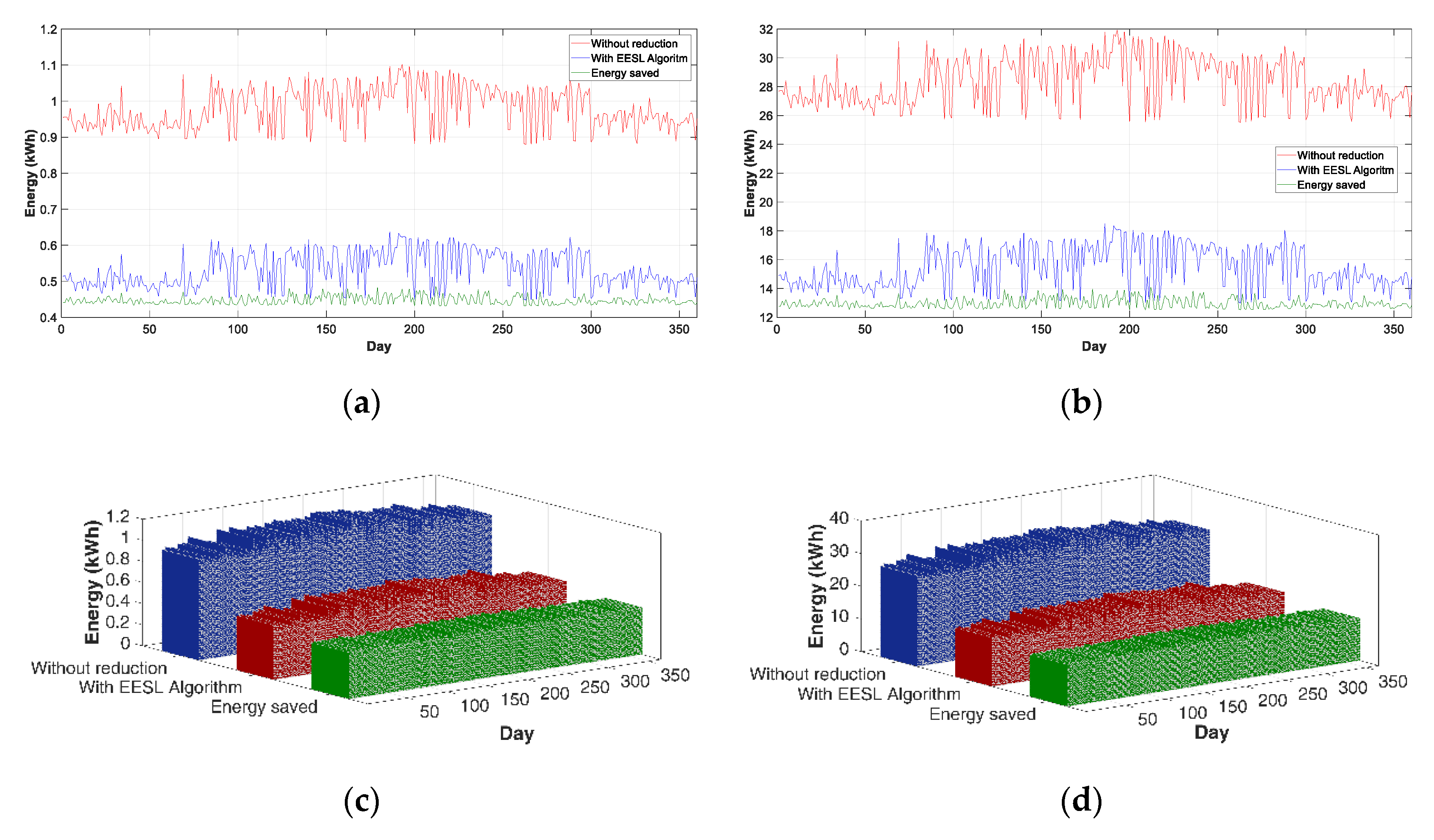
The annual study has been done in order to determine the operation of the system over an extended period of time, including all seasons of the year. The study was done from 1 September 2018 to 1 September 2019. Figure 21 shows the result of the study performed.
In Table 10, the energy saved obtained by each MCDSL can be observed, with the two proposed flow reduction levels and through the application of the EESL algorithm. The last column of the table reflects the energy savings in the total MCDSLs installed.

5. Conclusions

This study developed and successfully evaluated a new system for real-world SL facilities that is both accurate and low-cost. This system is based on the Arduino open-source electronic platform. Input data were gathered with a set of sensors based on Arduino components.
This system has a number of advantages. In fact, MCDSL is able to perform real-time monitoring with high resolution time data, every 5 s, and able to be modified depending on the resolution of the monitoring. Evidently, this real-time calculation capability and the support of large data in the cloud have applications in real systems.
Three devices have been developed for the GWLN, MCDSL, and LLMD units, which allow the configuration of a complete monitoring and control system of the SLs, and achieve energy savings in the control of the SL. It can also be adapted to other types of luminaires with different regulations within the same system.
The developed system allows to control the SLs and to monitor the electrical variables (MCDSL), and also measures the levels of illumination (LLMD). The devices are located on the campus of the administrative area.
This research provided a new EESL algorithm to improve the energy efficiency of SLs, with data collection in real public lighting installations with high temporal resolution.
The results obtained show that the GWLN has a lower rate of lost packages, with a PLR of less than 4%, and ToA parameters have an average time for all devices around 35 ms. The data sent to the cloud with Firebase has an upload rate of 5 s. Firebase allows an upload speed of 200 ms, a characteristic that makes it possible to adapt the time for sending packets on the LoRa network, with shorter time intervals.
The system developed makes it possible to obtain satisfactory energy savings, improving the energy efficiency of the SL installation, and increasing the energy sustainability of the whole.
The proposed system can accommodate many different realities of other installations, ensuring scalability, interoperability, and accessibility (in the sense that the system is accessible from multiple platforms: mobile phone, PC, tablet), and its ease of deployment, with the case study of its implementation in a section of SLs in smart cities.

Author Contributions

All authors have contributed actively and fundamentally to the development of the presented work. And A.C.-O. and F.S.S. have developed the hardware and software design, assembled the prototypes and have designed and carried out the tests. The writing of the paper has been done by each author attending to their corresponding part of the development of the work. All authors have read and agreed to the published version of the manuscript.

Funding

This research received no external funding.

Acknowledgments

The authors would like to thank the Department of Electrical Engineering of the University of Jaén. for allowing the use of their laboratories and material in the development of this research.

Conflicts of Interest

The authors declare no conflict of interest.

Abbreviations

The following abbreviations are used in this manuscript:
AMR3Arduino Mega R3
AUR3Arduino Uno R3
BWBandwidth
CFCarrier Frequency
CRCode Rate
CRCCyclic Redundancy Check
DLSDragino LoRa Shield
DLGSDragino LoRa GPS Shield
EActive energy
EEEnergy Efficiency
EESLEnergy Efficiency for Street Lights
FECForward error correction
GPSGlobal Positioning System
GWLNGateWay LoRa Network
LLMDLighting Level Measurement Device
I2CInter-Integrated Circuit
IoTInternet of Things
LLevel
LEDLight Emitting Diode
LLMDLighting Level Measurement Device
LoRaLong Range
LoRaWANLong Range Wide Area Network
LPWANLow Power Wide Area Network
MCDSLMeasure and Control Device for Street Lights
NNumber
PActive power
PIRPassive infrared
PFPower factor
PLPayLoad
PLRPacket Lost Rate
PZEMPZEM-004t
RMSRoot Mean Square
RSSIReceived Signal Strength Indicator
SFSpreading Factor
SLStreet Light
SNRSignal-to-Noise Ratio
tTime
ToATime on Air
Wi-FiWireless Fidelity
WMPArduino Wemos Mini Pro
WNSWireless Sensor Networks
Greek symbols
εMeasuring error
µmean
σstandard deviation
Subscripts
bbaseline
curactual
levlevel
minminimum
maxmaximum
ppreamble
peoperation equivalent
PHYsymbols transmitted in the physical message
pkpacket
rreduced
savsaved
symsymbol
threthreshold

References

  1. Kabalci, Y.; Ersan Kabalci, E.; Padmanaban, S.; Holm-Nielsen, J.B.; Blaabjerg, F. Internet of Things Applications as Energy Internet in Smart Grids and Smart Environments. Electronics 2019, 8, 972. [Google Scholar] [CrossRef] [Green Version]
  2. Weber, M.; Podnar Žarko, I. A Regulatory View on Smart City Services. Sensors 2019, 19, 415. [Google Scholar] [CrossRef] [PubMed] [Green Version]
  3. Wojnicki, I.; Komnata, K.; Kotulski, L. Comparative Study of Road Lighting Efficiency in the Context of CEN/TR 13201 2004 and 2014 Lighting Standards and Dynamic Control. Energies 2019, 12, 1524. [Google Scholar] [CrossRef] [Green Version]
  4. Kostic, M.; Djokic, L. Recommendations for energy efficient and visually acceptable street lighting. Energy 2009, 34, 1565–1572. [Google Scholar] [CrossRef]
  5. Sedziwy, A.; Kotulski, L. Towards Highly Energy-Efficient Roadway Lighting. Energies 2016, 9, 263. [Google Scholar] [CrossRef]
  6. Beccali, M.; Bonomolo, M.; Ciulla, G.; Galatioto, A.; Lo Brano, V. Improvement of energy efficiency and quality of street lighting in South Italy as an action of Sustainable Energy Action Plans. The case study of Comiso (RG). Energy 2015, 92, 394–408. [Google Scholar] [CrossRef] [Green Version]
  7. Gutierrez-Escolar, A.; Castillo-Martinez, A.; Gomez-Pulido, J.M.; Gutierrez-Martinez, J.M.; Stapic, Z.; Medina-Merodio, J.A. A Study to Improve the Quality of Street Lighting in Spain. Energies 2015, 8, 976–994. [Google Scholar] [CrossRef] [Green Version]
  8. Carli, R.; Dotoli, M.; Pellegrino, R. A decision-making tool for energy efficiency optimization of street lighting. Comput. Oper. Res. 2018, 96, 222–234. [Google Scholar] [CrossRef]
  9. Sikora, R.; Markiewicz, P.; Pabjanczyk, W. Computing Active Power Losses Using a Mathematical Model of a Regulated Street Luminaire. Energies 2018, 11, 1386. [Google Scholar] [CrossRef] [Green Version]
  10. Djuretic, A.; Kostic, M. Actual energy savings when replacing high-pressure sodium with LED luminaires in street lighting. Energy 2018, 157, 367–378. [Google Scholar] [CrossRef]
  11. Yao, J.; Zhang, Y.; Yan, Z.; Li, L. A Group Approach of Smart Hybrid Poles with Renewable Energy, Street Lighting and EV Charging Based on DC Micro-Grid. Energies 2018, 11, 3445. [Google Scholar] [CrossRef] [Green Version]
  12. Bellido-Outeiriño, F.J.; Quiles-Latorre, F.J.; Moreno-Moreno, C.D.; Flores-Arias, J.M.; Moreno-García, I.; Ortiz-López, M. Streetlight Control System Based on Wireless Communication over DALI Protocol. Sensors 2016, 16, 597. [Google Scholar] [CrossRef] [PubMed] [Green Version]
  13. Hadipour, M.; Farrokhi Derakhshandehb, J.; Aghazadeh Shiranc, M.; Rezaei, R. Automatic washing system of LED street lighting via Internet of Things. Internet Things 2018, 1, 74–80. [Google Scholar] [CrossRef]
  14. Mohandasa, P.; Sheebha, J.; Dhanarajb, A.; Xiao-Zhi, G. Artificial Neural Network based Smart and Energy Efficient Street Lighting System: A Case Study for Residential area in Hosur. Sustain. Cities Soc. 2019, 48, 101499. [Google Scholar] [CrossRef]
  15. Mumtaz, Z.; Ullah, S.; Ilyas, Z.; Aslam, N. An Automation System for Controlling Streetlights and Monitoring Objects Using Arduino. Sensors 2018, 18, 3178. [Google Scholar] [CrossRef] [Green Version]
  16. Kaminska, A.; Ozadowicz, A. Lighting Control Including Daylight and Energy Efficiency Improvements Analysis. Energies 2018, 11, 2166. [Google Scholar] [CrossRef] [Green Version]
  17. Castillo-Martinez, A.; Medina-Merodio, J.A.; Gutierrez-Martinez, J.M.; Aguado-Delgado, J.; de-Pablos-Heredero, C.; Otón, S. Evaluation and Improvement of Lighting Efficiency in Working Spaces. Sustainability 2018, 10, 1110. [Google Scholar] [CrossRef] [Green Version]
  18. Ping Lau, S.; Merrett, G.V.; Weddell, A.S.; Neil, M. White A traffic-aware street lighting scheme for Smart Cities using autonomous networked sensors. Comput. Electr. Eng. 2015, 45, 192–207. [Google Scholar]
  19. Jagadeesha, Y.M.; Akilesha, S.; Karthika, S. Prasantha Intelligent Street Lights. Procedia Technol. 2015, 21, 547–551. [Google Scholar] [CrossRef] [Green Version]
  20. Sánchez, L.; Elicegui, I.; Cuesta, J.; Muñoz, L.; Lanza, J. Integration of Utilities Infrastructures in a Future Internet Enabled Smart City Framework. Sensors 2013, 13, 14438–14465. [Google Scholar] [CrossRef] [Green Version]
  21. Wojnicki, I.; Kotulski, L. Improving Control Efficiency of Dynamic Street Lighting by Utilizing the Dual Graph Grammar Concept. Energies 2018, 11, 402. [Google Scholar] [CrossRef] [Green Version]
  22. Kovacs, A.; Batai, R.; Csan, B.; Dudas, P.; Haya, B.; Pedone, G.; Revesz, T.; Vancza, J. Intelligent control for energy-positive street lighting. Energy 2016, 114, 40–51. [Google Scholar] [CrossRef] [Green Version]
  23. Elejoste, P.; Angulo, I.; Perallos, A.; Chertudi, A.; García Zuazola, I.J. An Easy to Deploy Street Light Control System Based on Wireless Communication and LED Technology. Sensors 2013, 13, 6492–6523. [Google Scholar] [CrossRef] [PubMed]
  24. Ożadowicz, A.; Grela, J. Energy saving in the street lighting control system—A new approach based on the EN-15232 standard. Energy Effic. 2017, 10, 563–576. [Google Scholar] [CrossRef] [Green Version]
  25. Leccese, F.; Cagnetti, M.; Trinca, D. A Smart City Application: A Fully Controlled Street Lighting Isle Based on Raspberry-Pi Card, a ZigBee Sensor Network and WiMAX. Sensors 2014, 14, 24408–24424. [Google Scholar] [CrossRef] [Green Version]
  26. Rabaza, O.; Molero-Mesa, E.; Aznar-Dols, F.; Gómez-Lorente, D. Experimental Study of the Levels of Street Lighting Using Aerial Imagery and Energy Efficiency Calculation. Sustainability 2018, 10, 4365. [Google Scholar] [CrossRef] [Green Version]
  27. Pasolini, G.; Buratti, C.; Feltrin, L.; Flavio Zabini, F.; De Castro, C.; Verdone, R.; Andrisano, O. Smart City Pilot Projects Using LoRa and IEEE802.15.4 Technologies. Sensors 2018, 18, 1118. [Google Scholar] [CrossRef] [Green Version]
  28. LPWA Technologies Unlock New IoT Market Potential. Machina Research. Nov. 2015. Available online: https://www.lora-alliance.org/portals/0/documents/whitepapers/LoRa-Alliance-Whitepaper-LPWA-Technologies.pdf (accessed on 10 December 2019).
  29. Vangelista, L.; Zanella, A.; Zorzi, M. Long-Range IoT Technologies: The Dawn of LoRa. Future Access Enablers of Ubiquitous and Intelligent Infrastructures; Springer: Berlin/Heidelberg, Germany, 2015; pp. 51–58. [Google Scholar]
  30. LoRa Alliance. Available online: https://lora-alliance.org (accessed on 10 December 2019).
  31. De Carvalho Silva, J.; Rodrigues, J.J.P.C.; Alberti, A.M.; Solic, P.; Aquino, A.L.L. LoRaWAN—A Low Power WAN Protocol for Internet of Things: A Review and Opportunities. In Proceedings of the 2nd International Multidisciplinary Conference on Computer and Energy Science (SpliTech), Split, Croatia, 12–14 July 2017. [Google Scholar]
  32. Wydra, M.; Kubaczynski, P.; Mazur, K.; Ksiezopolski, B. Time-Aware Monitoring of Overhead Transmission Line Sag and Temperature with LoRa Communication. Energies 2019, 12, 505. [Google Scholar] [CrossRef] [Green Version]
  33. Angrisani, L.; Bonavolontà, F.; Liccardo, A.; Schiano, R. On the Use of LoRa Technology for Logic Selectivity in MV Distribution Networks. Energies 2018, 11, 3079. [Google Scholar] [CrossRef] [Green Version]
  34. Paredes-Parra, J.M.; García-Sánchez, A.J.; Mateo-Aroca, A.; Molina-García, A. An Alternative Internet-of-Things Solution Based on LoRa for PV Power Plants: Data Monitoring and Management. Energies 2019, 12, 881. [Google Scholar] [CrossRef] [Green Version]
  35. Cano-Ortega, A.; Sánchez-Sutil, F.J. Monitoring of the Efficiency and Conditions of Induction Motor Operations by Smart Meter Prototype Based on a LoRa Wireless Network. Electronics 2019, 8, 1040. [Google Scholar] [CrossRef] [Green Version]
  36. CEN/TR 13201e1:2014, Light and Lighting, Road Lighting e Part 1: Performance Requirements. Available online: https://www.en-standard.eu/csn-en-13201-1-4-road-lighting/ (accessed on 10 December 2019).
  37. DIN EN 13201-2: 2016—Road Lighting—Part 2: Performance Requirement. Available online: https://www.en-standard.eu/csn-en-13201-1-4-road-lighting/ (accessed on 10 December 2019).
  38. Noreen, U.; Bounceur, A.; Clavier, L. A Study of LoRa Low Power and Wide Area Network Technology. In Proceedings of the International Conference on Advanced Technologies for Signal and Image Processing (ATSIP), Fez, Morocco, 22–24 May 2017. [Google Scholar]
  39. Phung, K.H.; Hieu Tran, H.; Nguyen, Q. Analysis and Assessment of LoRaWAN. In Proceedings of the 2nd International Conference on Recent Advances in Signal Processing, Telecommunications & Computing (SigTelCom), Ho Chi Minh, Vietnam, 29–31 January 2018. [Google Scholar]
  40. Bouguera, T.; Diouris, J.F.; Chaillout, J.J.; Jaouadi, R.; Andrieux, G. Energy Consumption Model for Sensor Nodes Based on LoRa and LoRaWAN. Sensors 2018, 18, 2104. [Google Scholar] [CrossRef] [PubMed] [Green Version]
  41. Polonelli, T.; Brunelli, D.; Marzocchi, A.; Benini, L. Slotted ALOHA on LoRaWAN-Design. Analysis and Deployment. Sensors 2019, 19, 838. [Google Scholar] [CrossRef] [Green Version]
  42. Sornin, N.; Yegin, A. LoRaWANTM 1.1 Specification. 2017. Available online: https://lora-alliance.org/sites/default/files/2018-04/lorawantm_specification_-v1.1.pdf (accessed on 10 December 2019).
  43. LoRa Alliance Technical Committee Regional Parameters Workgroup. LoRaWANTM 1.1 Regional Parameters. 2018. Available online: https://lora-alliance.org/sites/default/files/2018-04/lorawantm_regional_parameters_v1.1rb_-_final.pdf (accessed on 10 December 2019).
  44. Arduino Home. Available online: https://store.arduino.cc/arduino-uno-rev3 (accessed on 15 October 2019).
  45. Dragino LoRa Shield for Arduino. Available online: https://www.dragino.com/products/module/item/102-lora-shield.html (accessed on 10 December 2019).
  46. Wemos Electronics. Available online: https://wiki.wemos.cc/products:d1:d1_mini_pro (accessed on 10 December 2019).
  47. Dragino LoRa GPS Shield for Arduino. Available online: http://www.dragino.com/products/lora/item/108-lora-gps-shield.html (accessed on 10 December 2019).
  48. Ningbo Peacefair Electronic Co., Ltd. Available online: https://peacefair.en.made-in-china.com (accessed on 10 December 2019).
  49. Arduino Mega Rev3. Available online: https://store.arduino.cc/mega-2560-r3 (accessed on 10 December 2019).
  50. RobotDyn AC Dimmer. Available online: https://robotdyn.com/ac-light-dimmer-module-1-channel-3-3v-5v-logic-ac-50-60hz-220v-110v.html (accessed on 10 December 2019).
  51. Adafruit TSL2561. Available online: https://www.adafruit.com/product/439 (accessed on 10 December 2019).
  52. Arduino MKR WAN 1300. Available online: https://store.arduino.cc/mkr-wan-1300 (accessed on 10 December 2019).
  53. Monteino. Available online: https://lowpowerlab.com/guide/moteino/ (accessed on 10 December 2019).
  54. Lopy4. Available online: https://docs.pycom.io/gettingstarted/connection/lopy4/ (accessed on 10 December 2019).
  55. Libelium. Available online: http://www.libelium.com/extreme-range-wireless-sensors-connectivity-through-buLLMDings-in-city-lora-868mhz-915mhz/ (accessed on 10 December 2019).
  56. Dragino LoRa Products. Available online: http://www.dragino.com/products/lora.html (accessed on 22 June 2019).
  57. Murata Electronics. Available online: https://wireless.murata.com/pub/RFM/data/type_abz.pdf (accessed on 10 December 2019).
  58. HOPERF Chip RFM95/96/97/98. Available online: https://cdn.sparkfun.com/assets/learn_tutorials/8/0/4/RFM95_96_97_98W.pdf (accessed on 10 December 2019).
  59. Semtech SX1276. Available online: https://www.semtech.com/products/wireless-rf/lora-transceivers/sx1276 (accessed on 10 December 2019).
  60. Semtech SX1272. Available online: https://www.semtech.com/products/wireless-rf/lora-transceivers/sx1272 (accessed on 10 December 2019).
  61. ACS712. Available online: https://www.sparkfun.com/datasheets/BreakoutBoards/0712.pdf (accessed on 10 December 2019).
  62. STC013 Dechang Electronics Co. Ltd. Available online: http://en.yhdc.com/product/SCT013-401.html (accessed on 10 December 2019).
  63. FZ0430 Voltage Sensor. Available online: http://www.ekt2.com/pdf/412_ARDUINO_SENSOR_VOLTAGE_DETECTOR.pdf (accessed on 10 December 2019).
  64. ZMPT101B Voltage Sensor. Available online: https://www.datasheet4u.com/datasheet-pdf/ETC/ZMPT101B/pdf.php?id=1031464 (accessed on 10 December 2019).
  65. Sánchez-Sutil, F.; Cano-Ortega, A.; Hernández, J.C.; Rus-Casas, C. Development and calibration of an open source, low-cost power smart meter prototype for PV household-prosumers. Electronics 2019, 8, 878. [Google Scholar] [CrossRef] [Green Version]
  66. Cano-Ortega, A.; Sánchez-Sutil, F.J.; Hernández, J.C. Power Factor Compensation using Teaching Learning Based Optimization and Monitoring System by Cloud Data Logger. Sensors 2019, 19, 2172. [Google Scholar] [CrossRef] [PubMed] [Green Version]
  67. BH1750 Illumination Sensor. Available online: http://rohmfs.rohm.com/en/products/databook/datasheet/ic/sensor/light/bh1721fvc-e.pdf (accessed on 10 December 2019).
  68. BTA16-600B Triac. Available online: https://www.alldatasheet.com/datasheet-pdf/pdf/440942/ISC/BTA16-600B.html (accessed on 10 December 2019).
  69. PIR Sensor LHI1778. Available online: https://www.alldatasheet.com/datasheet-pdf/pdf/14901/PERKINELMER/LHI778.html (accessed on 10 December 2019).
  70. BISS0001 Integrated Circuit. Available online: https://www.alldatasheet.com/datasheet-pdf/pdf/88732/ETC/BISS0001.html (accessed on 10 December 2019).
  71. HC-SR501 Motion Sensor. Available online: https://www.mpja.com/download/31227sc.pdf (accessed on 10 December 2019).
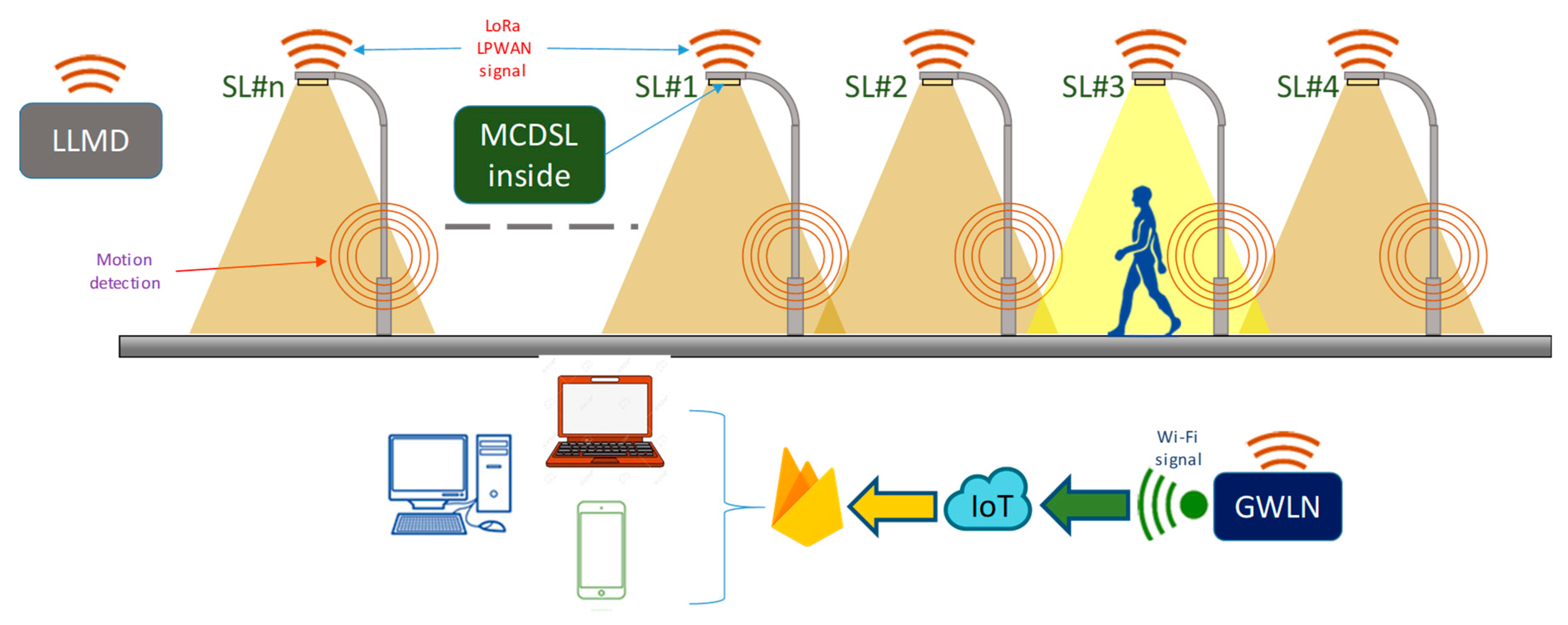
Figure 1. Architecture of SLs in campus.
Electronics 09 00124 g001
Figure 2. Hardware block diagram of GWLN.
Electronics 09 00124 g002
Figure 3. Wiring diagram of GWLN.
Electronics 09 00124 g003
Figure 4. Hardware block diagram of MCDSL.
Electronics 09 00124 g004
Figure 5. Wiring diagram of MCDSL.
Electronics 09 00124 g005
Figure 6. Hardware block diagram of LLMD.
Electronics 09 00124 g006
Figure 7. Wiring diagram of LLMD.
Electronics 09 00124 g007
Figure 8. GWLN main program.
Electronics 09 00124 g008
Figure 9. GWLN main program.
Electronics 09 00124 g009
Figure 10. Energy efficient street lights algorithm flow chart.
Electronics 09 00124 g010
Figure 11. LLMD main program.
Electronics 09 00124 g011
Figure 12. LLMD main program.
Electronics 09 00124 g012
Figure 13. CDO Lamp regulation: (a) Illumination; (b) Current; (c) Active power.
Electronics 09 00124 g013
Figure 14. SON Lamp regulation: (a) Illumination; (b) Current; (c) Active power.
Electronics 09 00124 g014aElectronics 09 00124 g014b
Figure 15. HPL Lamp regulation: (a) Illumination; (b) Current; (c) Active power.
Electronics 09 00124 g015
Figure 16. Illumination level test. (a) Comparison between luxmeter and LLMD with CDO lamp; (b) Luxmeter vs. LLMD; (c) Comparison between luxmeter and LLMD with SON lamp; (d) Luxmeter vs. LLMD; (e) Comparison between luxmeter and LLMD with HPL lamp; (f) Luxmeter vs. LLMD.
Electronics 09 00124 g016
Figure 17. Study of lighting levels: (a) Summer sunny day; (b) Winter sunny day; (c) Summer cloudy day; (d) Winter cloudy day.
Electronics 09 00124 g017
Figure 18. Pedestrian flow distribution.
Electronics 09 00124 g018
Figure 19. LoRa characteristic: (a) RSSI; (b) ToA; (c) PLR.
Electronics 09 00124 g019
Figure 20. Electrical variables. (a) Voltage; (b) Current; (c) Active power.
Electronics 09 00124 g020
Figure 21. Annual energy saved: (a) Active energy per lamp (kWh) 2D; (b) Total active energy (kWh) 2D; (c) Active energy per lamp (kWh) 3D; (d) Total active energy (kWh) 3D.
Electronics 09 00124 g021
Table 1. Analysis of wireless technologies used in SLs monitoring and control.
BibliographyParameters MeasuredNetwork TechnologiesSensorsBased on
[12]Electrical parametersWi-FiNot providedCC2530OEM module
[13]Weather parameters, Object detectionSIM900/GSM/SMSPIR Sensor
Dust Sensor
Rain Sensor
Arduino
[14]Light intensity,Not providedLighting Sensor
Motion Sensor
PIR Sensor
Not provided
[15]Object detection, Light intensityNot providedIR Sensor
LDR
Arduino Uno
[16]Illumination levelNot providedKNX Basic weather stationNot provided
[17]Illumination levelNot providedAmbient light sensorNot provided
[18]Local presenceLPWANRoad-user sensorNot provided
[19]Light intensityNot providedIR sensor, PIR sensorsAtmega128
[20]Presence detector, Light intensityLPWANPIR sensors, LDR, ISL76671, RADAR sensorWestermo GDW-11 485 GSM
[21]Electric parameters, Light intensityZigBeeMAVOLUX 5032 BNot provided
[22]Electric and weather parameters, Ambient lightLPWANNot providedPLC
[23]Humidity, temperature, light and infrared sensorLPWAN808H5V5, MCP9700A, EKMC, LDRATmega1281
[24]Lux and Temp sensorL-INXNot provided PLC
[25]Presence sensor WiMAXNot providedRaspberry-Pi
[26]Electrical parameters, LuminanceNot providedOrthoimagesGIS
[27]Illumination levelLPWANNot providedEMB-LR1272
Table 2. P lighting classes from EN 13201-2 [37].
ClassHorizontal IlluminanceAdditional Requirements
Horizontal Illuminance E (lux)Minimum Horizontal Illuminance Emin (lux)Minimum Vertical Illuminance Ev,min (lux)Minimum Semicylindrical Illuminance Esc,min (lux)
P115.03.005.005.00
P210.02.003.002.00
P37.501.502.501.50
P45.001.001.501.00
P53.000.601.000.60
P62.000.400.600.20
Table 3. GWLN components cost.
DescriptionNumberUnit Price (€)Total Price (€)
Microcontroller AUR3120.0020.00
Lora shield for Arduino DLS122.9122.91
Microcontroller WMP14.614.61
Power supply unit11.781.78
Box container16.986.98
auxiliary material and wiring11.451.45
Total cost 57.63
Table 4. MCDSL components cost.
DescriptionNumberUnit Price (€)Total Price (€)
Microcontroller AUM3128.0028.00
Lora GPS shield for Arduino DLGS135.9035.90
PZEM-004t110.0810.08
AC Dimmer13.223.22
Motion sensor HC SR50111.531.53
Power supply unit11.781.78
Box container16.986.98
auxiliary material and wiring12.032.03
Total cost 89.52
Table 5. LLMD components cost.
DescriptionNumberUnit Price (€)Total Price (€)
Microcontroller AUR3120.0020.00
Lora shield for Arduino DLS122.9122.91
Illumination sensor TSL256113.763.76
Power supply unit11.781.78
Box container16.986.98
auxiliary material and wiring11.051.05
Total cost 56.48
Table 6. Comparative measurements lighting level.
Distance (m)LLMDKonica MinoltaMeasuring Error (ε)
CDO (lx)SON (lx)HPS (lx)CDO (lx)SON (lx)HPS (lx)CDO (%)SON (%)HPS (%)
11024.5642196.874675.3041026.7192203.661675.4080.2160.0100.679
2830.000719.511195.838822.829720.931197.0470.7170.1210.142
3294.286408.264108.038294.916408.671107.9930.0630.0400.041
4158.018278.45170.670158.352279.26771.0060.0330.0340.082
5103.313211.02660.251102.827210.65361.0240.0490.0770.037
668.429172.41648.83068.322171.60848.6030.0110.0230.081
746.000130.90132.27246.236131.43732.0930.0240.0180.054
Table 7. Location of test devices.
DevicePlaceUTM Coordinates Zone 30
X (m) Y (m)
MCDSL #1SL #1431,3004,182,653
MCDSL #2SL #9431,4084,182,749
MCDSL #3SL #23431,3204,182,808
LLMDTerrace of administration building431,3084,182,777
Table 8. Transmission statistics.
DeviceRSSI (dBm)Time on Air (ms)Packets Lost Rate (%)
µσµσµσ
MCDSL #1−73.4301.51134.9892.9911.3520.235
MCDSL #2−94.8531.67934.9973.0072.0290.393
MCDSL #3−102.9362.99034.9832.9983.1580.958
LLMD−101.4173.89235.0013.0203.7501.967
Table 9. Packet transmission.
DevicePacket SendPacket DeliveryPacket LostPackets Delivery Rate (%)
MCDSL #1302402983140998.65
MCDSL #2302402962661497.97
MCDSL #3302402928595596.84
LLMD3024029106113496.25
Table 10. Energy saved (kWh).
TypeNSLESLEsav
EESL Algorithm296.126117.654
Flow reduction 40% (0:00–6:00)134.6853436.587
Flow reduction 20% (23:00–0:00, 6:00–7:00)22.265645.685
Total 4259.926