Abstract
The latest IEEE 802.11ax protocol has been launched to provide efficient services by adopting multi-user (MU) transmission technology. However, the MU transmissions in the aggregation-enabled wireless local area networks (WLANs) face two drawbacks when adopting the existing automatic repeat request (ARQ) schemes. (1) The failed packets caused by the channel noise can block the submission of subsequent packets and the transmission of queued ones. (2) When the lengths of aggregate media access control protocol data units (A-MPDU) transmitted by different users are varied, dummy bits should be added to the shorter frames to align the transmission duration. These drawbacks degrade the quality of service (QoS) performances, such as throughput, latency, and packet loss rate. In this paper, a novel QoS-aware backup padding ARQ (BP-ARQ) scheme for MU transmissions in the IEEE802.11ax WLANs is proposed to address these problems. The proposed scheme utilizes backups of selected packets instead of dummy bits to align the duration and to supress the influence of channel noise. An optimization problem that aims to improve the blocking problem of the failed packets is derived to determine the selection of packets. The promotion of the proposed scheme is well demonstrated by the simulations in NS-3.
1. Introduction
Recently, the wireless local area network (WLAN) has experienced rapid development and has become a popular wireless network access technique. With the vigorous development of Internet technology, constantly emerging applications and scenarios, such as cloud computing, industrial automation, smart healthcare, and ultra-high-definition live broadcast, necessitate stricter quality of service (QoS) requirements, such as higher throughput, lower latency, and less packet loss. The latest IEEE 802.11ax protocol was officially launched to conquer these bottlenecks [1,2]. In IEEE802.11ax WLANs, the transmission efficiency of the media access control (MAC) layer and the QoS performance are enhanced via the multi-user (MU) transmission technology, i.e., Orthogonal Frequency Division Multiple Access (OFDMA) and multi-user multi-input multi-output (MU-MIMO). The MU transmission technology enables the access point (AP) to distribute frames to multiple stations simultaneously (for downlink) and supports the concurrent transmission of frames from different stations to the AP (for uplink).
When scheduling the MU transmissions, the IEEE802.11ax WLANs adopt the aggregate MAC protocol data unit (A-MPDU) aggregation and block acknowledgment (BlockACK) for each user to reduce the MAC layer overhead. Under the error-prone channels, some sub-frames in the A-MPDU frame may be lost due to channel noise. Different automatic repeat request (ARQ) schemes ensure the reliability of transmission for aggregation-enabled WLANs. However, the MU transmissions face two drawbacks which degrade the performances of throughput, latency, and packet loss rate when the existing ARQ schemes schedule the retransmission of the lost packets indicated by the BlockACK/ACK frame:
(1) Since the WLANs maintain that packets are submitted to the upper layer in order, the lost packets can block the sliding of the aggregation window as described in [3]. That is, those successfully transmitted packets whose sequence numbers are greater than the smallest one among the lost packets should wait in the reordering buffer. Moreover, the queued packets cannot be served until their sequence numbers fall within the aggregation window. Because the originator has to wait for a new transmission opportunity to retransmit the lost packets and multiple retransmissions may be required when the channel quality is poor, the overall latency is increased.
(2) The lengths of A-MPDU frames transmitted by different users can be varied. One reason for this phenomenon is that the number and position of the lost packets in each A-MPDU frame of the MU transmission are random when the channel noise is independent between different users. In IEEE802.11ax WLANs, all users in the same MU transmission should have an identical transmission duration. When the transmission time requested by a user is less than the scheduled duration of the MU transmission, the user should add dummy bits called padding bits to the frame to make the transmission time equal to others. The transmission of the padding bits causes the loss of channel resources [4]. Consequently, the efficiency of the MU transmission decreases.
In this article, a novel backup padding ARQ (BP-ARQ) scheme for MU transmissions in IEEE802.11ax WLANs is presented to address the above problems. The key aspect of the proposed scheme is to utilize the remaining duration to transmit backups of selected packets from the A-MPDU when the scheduled duration is longer than the transmission time of the user. In the proposed scheme, an optimization problem is derived from the sliding of the aggregation window to determine the selected set of backups. A greedy algorithm is recommended to solve the optimization problem by searching for a sub-optimal solution considering the computational complexity and the processing time. The results in Section 4 illustrate that the performances of throughput, latency, and packet loss rate are all improved under the error-prone channels when the proposed scheme is adopted. The major contributions of this article are listed below:
- A novel ARQ scheme for the MU transmission in the aggregation-enabled WLANs is discussed.
- The proposed scheme is QoS-aware and protocol-friendly.
- The full utilization of the channel resource originally used for padding bits and the adequate sliding of the aggregation window are considered together in the proposed scheme.
- The measures to reduce the computational load and processing time are given to guarantee timely processing when the algorithm is implemented.
The remainder of the paper is organized as follows. In Section 2, the background and related work are introduced. In Section 3, we present the BP-ARQ scheme for MU transmissions in IEEE802.11ax WLANs. In Section 4, we illustrate the progress of the proposed scheme through a comparison with other schemes. We conclude the paper in Section 5.
2. Background and Related Works
2.1. The MU Transmission in the IEEE802.11ax WLANs
The IEEE802.11ax WLANs separate the channel bandwidth into resource units (RUs) that consist of multiple subcarriers for OFDMA operation. The frame exchange procedure of the downlink (DL) MU transmission in IEEE802.11ax WLANs is shown in Figure 1. For the DL MU transmission, the AP transmits an MU physical layer protocol data unit (PPDU) after the back-off procedure. The transmission time of different users in the MU PPDU is aligned by appending padding bits to the shorter A-MPDU frames. The RU allocation information of the MU PPDU is indicated in the HE-SIG-B subfield of the preamble. The scheduled stations can receive the A-MPDU frames in respective RUs according to the RU allocation information. After the transmission of the whole MU PPDU is finished, those stations can send the BlockACK/ACK frames to the AP in corresponding RUs.
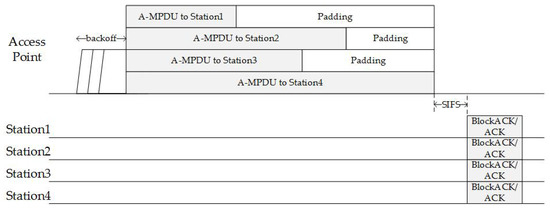
Figure 1.
The frame exchange procedure of the downlink (DL) multi-user (MU) transmission in IEEE802.11ax WLANs. A-MPDU (aggregate MAC protocol data unit). BlockACK (block acknowledgment). ACK (acknowledgment).
The frame exchange procedure of the uplink (UL) MU transmission is shown in Figure 2. For the UL MU transmission, the AP is responsible for the back-off procedure. The AP then transmits the buffer status report poll (BSRP) trigger frame to scheduled stations to collect the buffer status reports (BSR). The scheduled stations respond with the BSRs to indicate the amount of data waiting for transmission and to help the AP estimate the transmission time for them. The AP can allocate the transmission duration and RUs in the basic trigger frame according to the estimations. After receiving the basic trigger frame, each scheduled station can construct its A-MPDU frame and padding bits to stuff the transmission duration in the corresponding RU. After the reception of the trigger-based PPDU, the AP sends the BlockACK/ACK frames to those stations in corresponding RUs.
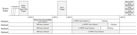
Figure 2.
The frame exchange procedure of the uplink (UL) MU transmission in IEEE802.11ax WLANs.
2.2. The ARQ Scheme in the Aggregation-Enabled WLANs
The ARQ scheme is one of the most important techniques to ensure the reliability of WLANs. For the aggregation-enabled WLANs, the BlockACK agreement should first be established to allow the A-MPDU transmissions via the add BlockACK (ADDBA) handshake. The BlockACK agreement maintains an aggregation window by the starting sequence number (SSN) and the window size, W. The aggregation window slides when the received packets are forwarded to the upper layer. The submission of the received packets follows the order of sequence numbers. If some packets are lost due to the channel noise, those successfully transmitted packets whose sequence numbers are greater than the failed packets should also wait in the reordering buffer for the retransmission of the failed packets. There are two typical ARQ schemes for aggregation-enabled WLANs, i.e., aggregation selective repeat ARQ (ASR-ARQ) [5,6,7,8] and block Acknowledgement window ARQ (BAW-ARQ) [3,9]. The ASR-ARQ aggregates the retransmitted packets and the queued packets, respectively. In the BAW-ARQ, the packets whose sequence numbers are in the window are allowed to be aggregated into an A-MPDU. Figure 3 and Figure 4 show the examples of the ASR-ARQ and the BAW-ARQ, respectively.
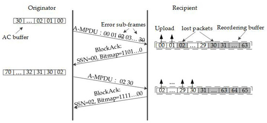
Figure 3.
An example of the A-MPDU transmission using the aggregation selective repeat automatic repeat request (ASR-ARQ) scheme where W = 64.
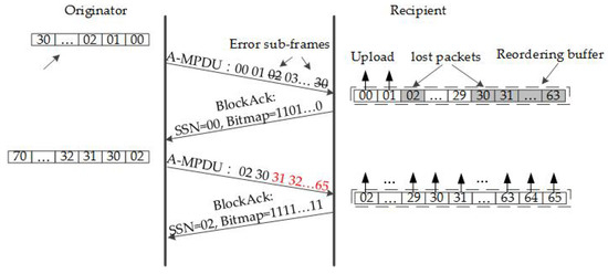
Figure 4.
An example of the A-MPDU transmission using the block Acknowledgement window automatic repeat request (BAW-ARQ) scheme where W = 64.
2.3. Related Works
A large number of published papers have shown that MU transmission performance has been enhanced via user scheduling and resource allocation. Bankov et al. [10] minimized the average upload time for unsaturated and UL scenarios by developing an algorithm to search for the best way to allocate the RUs. In [11], a set of the classic user schedulers was extended for UL OFDMA transmissions in IEEE802.11ax by adopting a general scheduling algorithm so that the performances of average upload time and throughput were improved. The control-aware low-latency scheduling algorithm in [12] supported more time-sensitive devices, with the latency constrained by allocating the radio resource based on the stability-inducing Lyapunov function. An adaptive-learning-based approach for a joint MU-MIMO user group and dynamic link configuration parameter selection was introduced to improve network performance in [13]. Bhattarai et al. [14] analyzed the influence of distributions of RA-RU and SA-RU on throughput and BSR delivery rate and maximized the throughput by optimally allocating the two kinds of RUs. In [15], a scheduler was proposed to increase RU allocation efficiency based on the information of QoS and buffered data. Bai et al. [16] proposed an adaptive grouping scheme to achieve the optimal efficiency of BSR delivery and improved the throughput when the Uplink OFDMA Random Access (UORA) mechanism was used.
Several works in the literature have been dedicated to the padding problem of MU transmissions. Some of them researched the duration allocation to improve the padding problem. In [17], two algorithms that determined the scheduled duration for the UL transmission were introduced. One algorithm fixed the scheduled duration, and the other considered padding overhead, energy, and fairness based on the queue sizes and channel conditions of users when the scheduled duration was allocated. Moriyama et al. [18] proposed a novel method that decided the frame aggregation size in MU-MIMO data to improve channel utilization at the cost of a certain delay performance. In [4], a novel data frame construction scheme for MU transmissions was proposed to maximize the transmission efficiency by calculating the optimal length according to the status of buffers and transmission rates. Others broke the rules of MU transmissions to enhance transmission efficiency. Lin et al. modified the structure of DL MU-MIMO and increased the efficiency by splicing frames from different users in one stream to stuff the channel time, which is called frame padding [19,20]. Wang et al. [21] characterized the frame padding problem as a multi-stream knapsack model and derived the optimal padding scheduler by investigating the inter-stream interference based on the model.
Some existing papers focused on the ARQ schemes of the aggregation-enabled WLANs. In [5] and [6], the ASR-ARQ scheme and the aggregated hybrid ARQ were proposed and the models of service time distribution were derived for them. In [7], the impacts of the ASR-ARQ scheme on MAC access delay and throughput were analyzed based on the proposed model for unsaturated networks. Hajlaoui et al. [8] expounded a mathematical model to investigate the saturated throughput using the ASR-ARQ scheme. Zhu et al. [22] enhanced the ASR-ARQ scheme via a method that aggregated the lost packets and their duplicates in the retransmitted A-MPDU when the number of lost packets was small. A throughput model of single-user transmissions was introduced to determine the execution threshold and the general duplicate times. Seytnazarov et al. [3] provided a theoretical model to evaluate the influence of the BAW-ARQ scheme on aggregation size and derived the access delay and the throughput under the saturated settings. In [9], an analytical model that conformed to the BAW-ARQ scheme was introduced to investigate the impact on saturation throughput.
Although all the above proposals investigated the performances of MU transmissions, or the aggregation-enabled ARQ schemes from different perspectives, none of them analyzed the performance of aggregation-enabled ARQ schemes together with MU transmissions, considered the full utilization of the channel resource originally used for padding bits in a protocol-friendly way or improved the blocking problem when the aggregation window slides. Therefore, we propose a novel QoS-aware BP-ARQ scheme to overcome these problems for MU transmissions in IEEE802.11ax WLANs.
3. Methods
3.1. The Architecture of the BP-ARQ Scheme
In this section, we design a novel BP-ARQ scheme for MU transmissions in IEEE802.11ax WLANs. The BP-ARQ scheme is extended from the BAW-ARQ because the BAW-ARQ is superior to the ASR-ARQ for MU transmissions according to the comparison in Section 4. Similar to the BAW-ARQ, the proposed scheme prepares the packets that satisfy the limitations of the duration, size, and aggregation window to be aggregated in the A-MPDU for each user in the MU transmission. These packets are called the prepared packets in the following analysis. The prepared packets in each A-MPDU have different sequence numbers and are arranged in order of sequence number. The sequence number of the l-th packet is defined as , where , and L donates the number of prepared packets in the A-MPDU.
The proposed scheme lengthens the A-MPDU of a user by attaching replicates of packets selected from the prepared ones instead of padding bits to align with the scheduled duration of the MU transmission when constructing the A-MPDU. The replicate of a packet is called the backup. In the proposed scheme, the number of backups for each packet can vary, so that the backups can fill as much of the remaining duration as possible.
The IEEE802.11ax devices that construct A-MPDUs according to the procedure of the BP-ARQ scheme are treated as the enhanced devices in this article. The BP-ARQ scheme is considered protocol-friendly because the enhanced devices can communicate with the traditional IEEE802.11ax ones normally. In the BP-ARQ scheme, the major modification of the protocol is to include backups in the A-MPDU, and other designs follow the rules of the MU transmission and A-MPDU aggregation. The modification can be implemented only in the originator of the A-MPDU, and the BP-ARQ scheme does not need to modify the procedure of receiving an A-MPDU in the recipient. The recipient can handle the A-MPDU as usual. Each sub-frame of the A-MPDU is processed independently. The order of received packets can be rearranged by the reordering buffer. The ability to detect and filter out a repeated frame is also mandatory in the IEEE802.11ax protocol because the successfully received packets are also retransmitted when the BlockACK/ACK frame is lost. Therefore, the traditional devices are equipped with the ability to receive and handle backups normally.
When the original sub-frame fails, the backup sub-frames in the same A-MPDU can act as if the packet is retransmitted. Consequently, the replicated packet is lost only when errors caused by the channel noise occur in both the original sub-frame and its backups simultaneously. The equivalent packet error rate (PER) of the l-th packet that is replicated for times is shown as follows:
where e represents the sub-frame error rate and is derived by
where is the length of the MPDU header, and is the length of the average payload. The is the bit error rate (BER), which reflects the characteristics of the physical channel occupied by the user. Thus, the proposed scheme enhances the successfully delivered possibility of the replicated packets under the error-prone channels.
Moreover, the higher successfully transmitted probability of the replicated packets also alleviates the blocking problem of the reordering buffer because the possibility that the replicated packets block the sliding procedure is also reduced. Figure 5 depicts an example of the BP-ARQ scheme where the remaining duration is enough for four backups in the first transmission. The BP-ARQ scheme utilizes the remaining duration of the user to transmit backups. Even if the BP-ARQ scheme is not implemented, the originator transmits the padding bits in the remaining duration. Therefore, the transmission of backups does not consume extra energy. On the other hand, when the original sub-frame fails and the packet is received via the backup ones, the energy of retransmitting the packet in a new transmission can be saved.
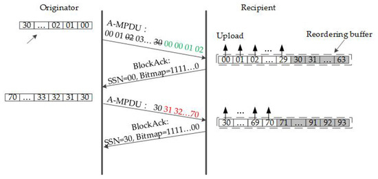
Figure 5.
An example of the A-MPDU transmission using the backup padding ARQ (BP-ARQ) scheme where W = 64.
3.2. The Formulation of the Optimization Problem Based on the Sliding of the Aggregation Window
Due to the limited remaining duration, increasing the number of backups for one packet means that the backups of others are reduced. As a result, the sliding of the aggregation window differs when different backup parameters are applied. Therefore, it is important to develop an algorithm that can adaptively determine the number of backups for each packet to achieve the best performance with the limited remaining duration. The proposed algorithm aims to find a group of backup parameters under the constraints so that the fastest sliding of the aggregation window, i.e., the maximum number of the uploaded packets, is expected after the transmission.
To estimate the number of uploaded packets after the transmission, the originator should obtain the status of the reordering buffer, i.e., the holes in the reordering buffer, and the number of successfully transmitted packets between two adjacent holes.
The sequence number of transmitted packets is assigned cyclically from 0 to 4095 by the originator. The originator is informed of the status of the reordering buffer by the BlockACK/ACK frame. The originator updates the aggregation window according to the bitmap and the starting sequence number in the BlockACK/ACK frame to ensure that there are holes in the reordering buffer ready for the prepared packets. Thus, the originator can calculate the number of successfully transmitted packets between two adjacent holes according to the sequence numbers of prepared packets.
Therefore, the number of successfully transmitted packets between the packet and the packet and that behind the last prepared packet are obtained by
where is the latest sequence number assigned by the originator. can be obtained from the sequence number assignment function.
The number of packets uploaded at the end of the transmission is defined as S. S depends on the transmission status of the prepared packets. Based on the upload patterns, three categories can be differentiated.
Category 1:
There are no packets uploaded.
As depicted in Figure 6, this category happens when the first packet in the A-MPDU fails, regardless of other packets. The probability distribution of the category is given by
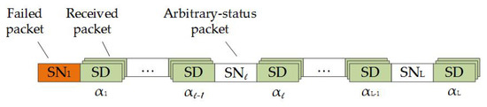
Figure 6.
The status of the reordering buffer after the transmission in Category 1. SD represents the successfully delivered packets in previous transmissions.
Category 2:
Some packets in the reordering buffer are uploaded, while other packets are still buffered, as shown in Figure 7.
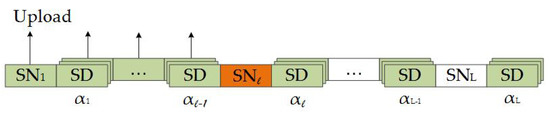
Figure 7.
The status of the reordering buffer after the transmission in Category 2.
A major requirement for this category is that packet failure occurs among the prepared packets, except for the first one. Therefore, those before the first failed packet can be uploaded, while others are not allowed. The probability distribution of the category when the first failed packet is the packet in the A-MPDU is calculated by:
Category 3:
All packets in the reordering buffer are uploaded. Figure 8 illustrates the status in the category.
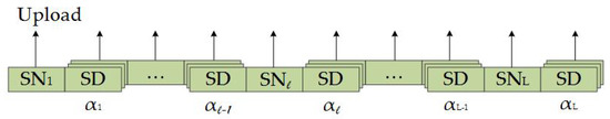
Figure 8.
The status of the reordering buffer after the transmission in Category 3.
This category is possible if all the packets in the A-MPDU are successfully transmitted. The probability distribution of the category is derived by
According to the architecture of the BP-ARQ scheme, the number of backups for each packet is described by a vector :
The expected number of packets uploaded at the end of the transmission is calculated by
Consequently, the optimization problem and the constraints that are derived according to the length limitation of the A-MPDU and the scheduled duration are formulated below:
The parameters are defined as follows: is the maximum length of the A-MPDU frame. is the physical data transmission rate of the user. is the scheduled duration of the MU transmission.
According to Equation (8), there is an upper bound on the objective function and the upper bound is calculated by
Because the domain of is discrete, the difference function is derived for the k-th dimension in . When is increased by 1, the difference of the objective functions is calculated by
Since the is positive and k is arbitrary, the objective function increases monotonically in every dimension of . Therefore, the objective function converges to when all the elements in approach infinity. However, the condition of converging to the upper bound is difficult to satisfy in the optimization problem because of the constraints. Therefore, the objective value is considered to converge to the upper bound when the difference between the upper bound and the objective value is smaller than the convergence accuracy, C.
The optimization problem described in Equation (9) is non-linear integer programming. Although the optimal solution can be obtained by verifying all the feasible solutions, it is difficult to enumerate all of them in a tolerable time because the number of feasible solutions explodes in some cases [23]. The number of feasible solutions is when the scheduled duration can contain N sub-frames in the A-MPDU frame. For example, when N is 64 and L is 32, there are more than feasible solutions. The time complexity of enumerating all the feasible solutions is and the space complexity is .
3.3. The Greedy Algorithm
Because the frame transmissions in the WLANs demand a timely response according to the scheduling mechanism of WLANs, a greedy algorithm [24], which searches for a sub-optimal solution but largely shortens the processing time, is recommended here. Moreover, three methods are adopted in the algorithm to further reduce the processing time by considering the computation load, the range of candidates, and parallel processing.
The greedy algorithm divides the original optimization problem into multiple steps, and there is a sub-problem in each step. For each sub-problem, the precondition is the result of previous steps. When the objective value does not converge to the upper bound, and the A-MPDU can contain another sub-frame according to the constraints, the sub-problem searches for one packet that achieves the best performance under the precondition and increases the number of backups for the packet by 1. In each step, the number of backups for each packet determined by the previous steps is defined as
and the initial status used in the first step is . Thus, the number of backups for each packet updated in the current step when the l-th packet is chosen is described as
The selection of packet in each step is based on the following equation:
After the optimal solutions in all sub-problems are found, the backup status updated in the last step is considered the sub-optimal solution of Equation (9). The time complexity of the greedy algorithm is , and the space complexity is .
To find the optimal solution for the sub-problem, we compare the objective values when two different solutions are applied, i.e., two different packets are selected, respectively. In each comparison, the candidate with a smaller sequence number is called the u-th packet, and another one is called the v-th packet. The difference between the two expected number of uploaded packets is derived as follows:
We define A as the sliding parameter between the u-th and v-th packets, and B as the sliding parameter behind the v-th packet. They are calculated by
so Equation (15) can be re-described as below:
Because other factors in Equation (18) are always positive, whether or not the result is positive, is determined by the decision function, which is given by
The decision function only depends on parameters of the prepared packets whose sequence number is greater than the smaller candidate between the two, so the computation load is reduced. In each comparison, the u-th packet is selected if is greater than zero; otherwise, the v-th packet is better. After all the candidates are compared, the optimal solution of the sub-problem is achieved.
For each sub-problem, the range of candidates can also be narrowed in advance according to the decision function. Because is definitely positive when is equal to , i.e., is equal to , the packet with the smallest sequence number is always selected among the packets that have the same number of backups in the precondition. Consequently, we can classify those packets into a group, and the comparisons are performed among packets whose sequence number is the smallest in their respective groups. As a result, the range of candidates in each step is dramatically narrowed.
Moreover, parallel processing is available thanks to the characteristics of the greedy algorithm. One of the characteristics is that the result of each step is part of the final solution for the optimization problem, and the result of each step is not changed by those obtained in the subsequent steps. According to the characteristic, the result of each step can be conveyed to the aggregation mechanism step by step. Consequently, the selection of the subsequent backups and the aggregation of the obtained backups can be conducted in parallel so that the overall processing time is shortened. Figure 9 illustrates the sequence diagrams without or with parallel processing.
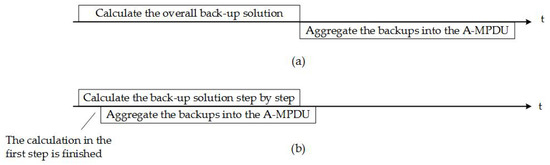
Figure 9.
The sequence diagrams of the calculation of the backup solution and the aggregation of the backups. (a) The sequence diagram without parallel processing. (b) The sequence diagram with parallel processing.
The BP-ARQ scheme introduces the modification to contain backups in the A-MPDU and the selection algorithm to determine which packets are replicated. The algorithm and the aggregation of backups are both implemented in the originator of A-MPDUs. The originator is AP in the DL MU transmissions, and the station acts as the originator in the UL MU ones. The procedure of the BP-ARQ scheme in the originator is shown in Figure 10. The sub-frame error rate is calculated according to the estimation of SNR and BER when the BlockACK/ACK frames are received. When a user is scheduled to transmit, the originator first tries to aggregate the packets from the AC buffer for the user based on the limitations of duration, frame size, and aggregation window. The parameters used in the backup procedure are then prepared. After the prepared packets are determined, the status of the reordering buffer is established according to Equation (3). The scheduled duration is equal to the maximum duration among the users for the downlink or the transmission duration indicated in the basic trigger frame for the uplink. After that, the greedy algorithm is conducted to solve the optimization problem step by step until there is not enough space or duration left to contain a sub-frame in the A-MPDU, or the objective value is considered to converge to the upper bound. At the end of each step, the replication of the selected packet and the aggregation of the backup are executed in the aggregation mechanism.
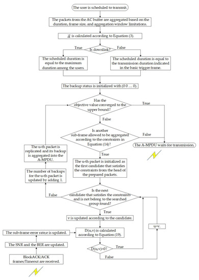
Figure 10.
The procedure of the BP-ARQ scheme.
The pseudo-code of the algorithm (Algorithm 1) is as follows.
| Algorithm 1 A greedy algorithm searching for the sub-optimal solution of the proposed scheme. |
|
4. Performance Evaluation
In this section, we evaluated the performances of the proposed scheme in the NS-3 simulator [25]. MU transmission was not supported by NS-3 when this paper was written. We extended the Wi-Fi modules of NS-3 to support the OFDMA-based MU transmission on the basis of the implementation in [26] and the description in the latest TGax documents.
An IEEE802.11ax WLAN was established for evaluation in the following experiments, as shown in Figure 11. There were uplink or downlink user datagram protocol (UDP) streams transmitted between all stations and the Access Point (AP). Consequently, only the transmission path in the WLAN was of concern here.
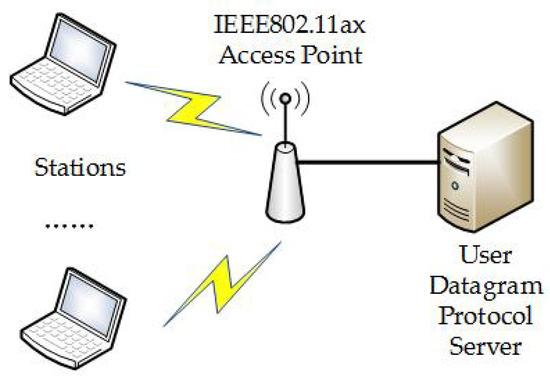
Figure 11.
The topology of the experimental network.
In the established WLAN, the bandwidth was 80 MHz, the PHY rate of the data frame was the Modulation and Coding Scheme (MCS) 9, the PHY rate of the control frame was MCS 0, and the number of spatial streams was 4. The packet lifetime in the WLAN was set to 500 ms, and the buffer size was adequate to accommodate the arrived packets. In the OFDMA scheduler, the size of RU is 106-tones, and the number of users at each round is 8. All the RUs are scheduled by AP in the UL MU transmission without adopting the optional UORA. Other settings of the MAC layer are listed in Table 1. The set of BER evaluated in the experiments is .

Table 1.
Parameters for the WLAN system.
The evaluation was conducted by comparing the proposed BP-ARQ scheme with the ASR-ARQ [5,6,7,8] and the BAW-ARQ [3,9] in the existing literature. The error bar in the following figures indicated the standard deviation of the simulation results.
The performance was compared via throughput, end-to-end delay, and packet loss rate. The throughput indicates the amount of data received by the UDP layer of the recipient per second and is calculated by
where is the number of received packets and represents the simulation time. The saturated throughput is measured under the saturated condition and the saturated condition is performed by offering excessive load. The end-to-end delay, , is defined as the time interval between when a packet is generated and when it reaches the UDP layer of the recipient and is given as
where is the moment when a packet is generated and is the instant of time when it reaches the UDP layer of the recipient. The packet loss rate (PLR) is the ratio between the number of packets that do not reach the destination and the number of offered packets and is derived as
where is the number of packets that do not reach the destination and is counted according to the UDP serial numbers of the received packets.
4.1. The Saturated Throughput
First, we investigated the saturated throughput of each station under different BERs. The number of stations was 20, and the access category of streams was identical. Figure 12a,b depict the throughput of each station against BERs for the downlink and the uplink, respectively. In both figures, the ASR-ARQ provides the lowest throughput because its aggregation efficiency and transmission efficiency are the lowest among the three. The ASR-ARQ only aggregates the failed packets in the retransmitted A-MPDUs so that the size of those A-MPDUs is relatively small and more padding bits should be added to align with other users. The BAW-ARQ is superior to the ASR-ARQ because the BAW-ARQ can aggregate the retransmitted and queued packet into an A-MPDU to lengthen the A-MPDU frame and increase the efficiency. The BP-ARQ outperforms the other two because the BP-ARQ fully utilizes the remaining duration to ensure that more packets are successfully transmitted. Moreover, the BP-ARQ also improves the blocking problem of the aggregation window so that more queued packets can be included in the next transmission.
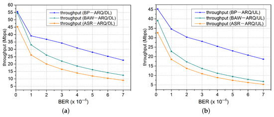
Figure 12.
The throughput of each station vs. the bit error rate (BER). (a) downlink. (b) uplink.
The performances in the downlink are better than those in the uplink because the AP needs extra overhead to gather the buffer information from scheduled stations to help allocate the duration in the uplink. Moreover, the buffer status report cannot reflect the blocking of the aggregation window. For the saturated condition, the buffer size in each station is much longer than the size of the aggregation window. When the AP allocates the duration based on the buffer status report, the remaining duration in the uplink is longer than that in the downlink.
In the downlink, the BP-ARQ improves the throughput by up to 82% compared to the BAW-ARQ and 151% compared to the ASR-ARQ. In the uplink, the two values are expanded to 171% and 250%, respectively. The promotion in the uplink is greater than that in the downlink because the remaining duration is longer in the uplink. This fact degrades the transmission efficiency of the ASR-ARQ and the BAW-ARQ, while provides more space to enhance the sliding of the aggregation window in the BP-ARQ.
In general, the BP-ARQ maintains the highest transmission efficiency and improves the throughput greatly under the error-prone channels.
4.2. The Latency and the Packet Loss Rate
We then studied the end-to-end delay and the packet loss rate under the error-prone channels when the data rate of the UDP stream was 20 Mbps. The number of stations was 20, and the access category of the streams was identical. Figure 13 illustrates the end-to-end delay and the packet loss rate in the uplink and downlink when the BER is varied. Due to the large range of the experimental results, the ordinate is plotted logarithmically in Figure 13.
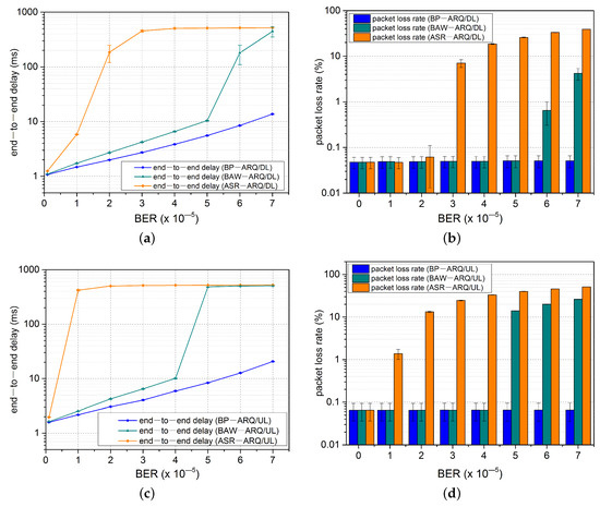
Figure 13.
The end-to-end delay and packet loss rate vs. the BER. (a) The end-to-end delay in the downlink. (b) The packet loss rate in the downlink. (c) The end-to-end delay in the uplink. (d) The packet loss rate in the uplink.
According to Figure 13, the performances of the end-to-end delay and the packet loss rate can be classified into two stages: the stable stage and the overload stage. At the stable stage, when the BER increases, the end-to-end delay follows a steadily increasing tendency with the degradation of the transmission capacity and the packet loss rarely occurs. At the overload stage, the transmission capacity is inferior to the arrival rate of the offered stream, so more and more packets accumulate in the AC buffer and the queuing delay is dramatically increased. Because the packets that exceed the lifetime limitation in the WLAN are dropped, the end-to-end delay is around 500 ms, while the explosion occurs in the packet loss rate at this stage.
In Figure 13a,b, when the BER is , the end-to-end delay of the three schemes is around 1 ms and the packet loss rates of them are around 0.05%. However, they follow different tendencies with the increase in the BER. The delay of the ASR-ARQ grows most rapidly when the BER is between and . The phenomenon is caused by the lowest transmission capacity because the padding problem is severe in the retransmitted A-MPDUs and the queued packets have to wait until the retransmissions of previous packets are finished before they can be transmitted in the ASR-ARQ. Due to it having the lowest transmission capacity, the ASR-ARQ enters the overload stage at a relatively small BER, and the packet loss rate of the ASR-ARQ is the highest among the three. As for the BAW-ARQ and the BP-ARQ, both experience the stable stage at a larger range of the BER because they can aggregate the retransmitted packets and the queued packets into an A-MPDU to enhance the transmission efficiency and reduce the queuing delay. When the BER is less than , the BP-ARQ outperforms the BAW-ARQ by up to 50% because the BP-ARQ accelerates the sliding of the aggregation window to reduce the waiting time in the reordering buffer. When the BER is further increased, the delay of BAW-ARQ also enters the overload stage, while that of the BP-ARQ is still stable and under 11 ms. Moreover, the packet loss rate of the BAW-ARQ also faces a tremendous increase to 4.2%, while that of the BP-ARQ is still around 0.05%. The reason for the differences is that accelerating the sliding of the aggregation window also enhances the transmission capacity of the BP-ARQ.
The tendencies in Figure 13c,d are similar to those in the downlink. However, the performances in the uplink are inferior to those in the downlink because more scheduled overhead reduces the transmission capacity in the uplink. As a result, the ASR-ARQ and the BAW-ARQ enter the overload stage at thresholds, which are lower than those in the downlink. Their packet loss rates are also much higher than those in the downlink. In contrast, the BP-ARQ can still maintain the stable stage for given BERs in the uplink.
Consequently, compared to the ASR-ARQ and the BAW-ARQ, the BP-ARQ shows the strongest tolerance of channel noise and provides stable end-to-end delay and a low packet loss rate for any given BER in the experiments.
4.3. Priority-Based Network Performance
Finally, the performance of the priority-based network was evaluated. Because we confirmed that the ASR-ARQ is inferior to the BAW-ARQ for the multi-user transmissions in Section 4.1 and Section 4.2, the BP-ARQ was compared with the BAW-ARQ in this subsection.
The number of stations in the network was 10. There were three streams whose access categories were AC_VO (voice), AC_VI (video), and AC_BE (best effort) transmitting between the AP and each station. The data rate of each stream was 10 Mbps. We researched the end-to-end delay and packet loss rate for the AC_VO and AC_VI streams and the throughput for the AC_BE. The selection of served streams was conducted by the virtual back-off procedure based on the parameters in Table 2.
Table 2.
Parameters for the virtual back-off procedure.
Figure 14 shows the QoS performances in the downlink. The packet loss rates of the BP-ARQ and the BAW-ARQ are all around 0.04% for the AC_VO and AC_VI, while the BP-ARQ outperforms the BAW-ARQ in terms of the end-to-end delay. The reduction of the end-to-end delay for the AC_VI is up to 4 ms, and that for the AC_VO is up to 30 ms. The reduction for the AC_VO is greater because the streams with a lower priority wait longer to obtain a new transmission opportunity. The aggregation window slides more slowly for the lower-priority stream in the BAW-ARQ because the retransmission is scheduled in a new transmission opportunity, but the BP-ARQ improves the circumstance. For the AC_BE, the BP-ARQ has a greater throughput than the BAW-ARQ. In the BP-ARQ, low-priority streams have more chances to transmit because high-priority streams have a lower probability of contending for a new transmission opportunity in the case of retransmitted packets. On the other hand, lower-priority streams have fewer transmission opportunities, which causes the arrived packets to accumulate in the buffer. The BP-ARQ enhances the transmission efficiency for the AC_BE by including more new packets in the aggregation window.
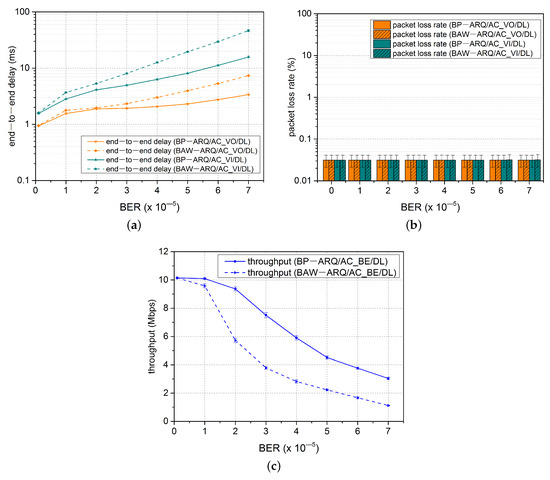
Figure 14.
The QoS performances vs. the BER in the downlink. (a) The end-to-end delay of the AC_VO (voice) and AC_VI (video) traffics. (b) The packet loss rates of the AC_VO and AC_VI traffics. (c) The throughput of the AC_BE (best effort) traffic in each station.
In Figure 15, the QoS performances for the uplink are illustrated. In the uplink, streams with different access categories tend to be transmitted in the same MU PPDU because the access category of the stream transmitted in each RU is determined by the station. Therefore, the higher-priority stream has more remaining duration that should be padded. The remaining duration reduces the transmission capacity in the BAW-ARQ, while it loosens the constraints to improve the sliding of the aggregation window in the BP-ARQ. Consequently, the end-to-end delay of the BP-ARQ is reduced by up to 90% compared to that of the BAW-ARQ for the AC_VO. Although the BAW-ARQ or the BP-ARQ cannot guarantee the low latency and packet loss rate for the AC_VI when the BER exceeds a threshold, the BP-ARQ shows a stronger tolerance of channel noise with a higher threshold. In terms of the throughput for the AC_BE, the difference between the BP-ARQ and BAW-ARQ is enlarged when the BER is less than and shrinks as the BER is increased. When the BER is increased, the retransmissions of high-priority streams are more frequent in the BP-ARQ and squeeze the transmission opportunities of low-priority streams. Consequently, the BP-ARQ improved the performance of the end-to-end delay and packet loss rate for the AC_VO and AC_VI streams and enhanced the throughput for the AV_BE compared to the BAW-ARQ.
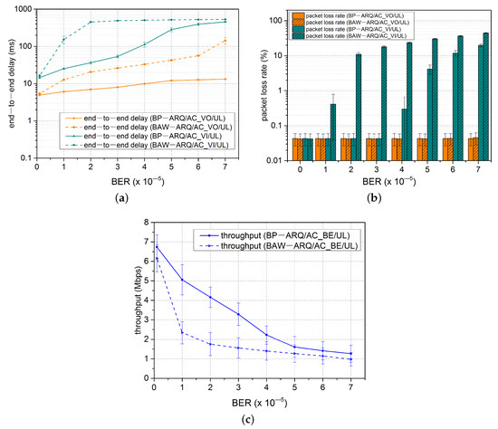
Figure 15.
The QoS performances vs. the BER in the uplink. (a) The end-to-end delay of the AC_VO and AC_VI traffics. (b) The packet loss rates of the AC_VO and AC_VI traffics. (c) The throughput of the AC_BE traffic in each station.
5. Conclusions
In this paper, a novel QoS-aware backup padding ARQ scheme for MU transmissions in IEEE802.11ax WLANs was proposed to enhance the transmission efficiency and the sliding of the aggregation window. The simulation results showed that the proposed scheme increased the throughput by up to 171% and 250%, reduced the latency by up to 98.2% and 98.9%, and increased the threshold of BER where the packet loss rate exceeded 0.1% by up to 60% and 700% compared to the BAW-ARQ and the ASR-ARQ, respectively. Moreover, the proposed scheme also enhanced the performance of traffic with different priorities in the priority-based network. Consequently, this work is critical for achieving low-latency and reliable communications and satisfying the QoS requirements of emerging applications. Nevertheless, the proposed scheme may suffer from frequent retransmissions when the BER is further increased. Hence, it is recommended to study the proposed scheme together with rate adaptation in the future.
Author Contributions
Conceptualization, C.L. and B.W.; Methodology, C.L., L.W., and Y.T.; Software, C.L. and Y.T.; Validation, C.L. and L.W.; Writing—original draft preparation, C.L.; Writing—review and editing, C.L., L.W., Z.W., Y.T., and B.W.; Project administration, L.W. and B.W.; Funding acquisition, B.W.; Supervision, B.W. All authors have read and agreed to the published version of the manuscript.
Funding
This research was funded by the National Major Science and Technology Program of China grant number 2013ZX03004007.
Conflicts of Interest
The authors declare that there is no conflict of interest.
References
- Part 11: Wireless LAN Medium Access Control (MAC) and Physical Layer (PHY) Specifications; Amendment 1: Enhancements For High Efficiency WLAN, IEEE P802.11ax Draft 6.0; IEEE: Piscataway, NJ, USA, 2019.
- IEEE Standard for Information Technology-Telecommunications and Information Exchange Between Systems Local and Metropolitan Networks-Specific Requirements, Part 11: Wireless LAN Medium Access Control (MAC) and Physical Layer (PHY) Specifications; IEEE: Piscataway, NJ, USA, 2016.
- Seytnazarov, S.; Choi, J.-G.; Kim, Y.-T. Enhanced Mathematical Modeling of Aggregation-Enabled WLANs with Compressed BlockACK. IEEE Trans. Mob. Comput. 2019, 18, 1260–1273. [Google Scholar] [CrossRef]
- Kim, S.; Yun, J. Efficient Frame Construction for Multi-User Transmission in IEEE 802.11 WLANs. IEEE Trans. Veh. Technol. 2019, 68, 5859–5870. [Google Scholar] [CrossRef]
- Feng, K.-T.; Huang, Y.-Z.; Lin, J.-S. Design of MAC-defined aggregated ARQ schemes for IEEE 802.11 n networks. Wirel. Netw. 2011, 17, 685–699. [Google Scholar] [CrossRef]
- Lin, J.-S.; Feng, K.-T.; Huang, Y.-Z.; Wang, L.-C. Novel design and analysis of aggregated ARQ protocols for IEEE 802.11n networks. IEEE Trans. Mobile Comput. 2013, 12, 556–570. [Google Scholar]
- Karmakar, R.; Swain, P.; Chattopadhyay, S.; Chakraborty, S. Performance modeling and analysis of high throughput wireless media access with QoS in noisy channel for different traffic conditions. In Proceedings of the IEEE International Conference on Communication Systems and Networks (COMSNETS), Bangalore, India, 5–10 January 2016; pp. 1–8. [Google Scholar]
- Hajlaoui, N.; Jabri, I.; Ben Jemaa, M. An accurate two dimensional Markov chain model for IEEE 802.11n DCF. Wirel. Netw. 2018, 24, 1019–1031. [Google Scholar] [CrossRef]
- Mansour, K.; Jabri, I.; Ezzedine, T. Revisiting the IEEE 802.11n A-MPDU Retransmission Scheme. IEEE Commun. Lett. 2019, 23, 1097–1100. [Google Scholar] [CrossRef]
- Bankov, D.; Didenko, A.; Khorov, E.; Loginov, V.; Lyakhov, A. IEEE 802.11ax uplink scheduler to minimize, delay: A classic problem with new constraints. In Proceedings of the IEEE 28th Annual International Symposium on Personal, Indoor, and Mobile Radio Communications (PIMRC), Montreal, QC, Canada, 8–13 October 2017; pp. 1–5. [Google Scholar]
- Bankov, D.; Didenko, A.; Khorov, E.; Lyakhov, A. OFDMA Uplink Scheduling in IEEE 802.11ax Networks. In Proceedings of the 2018 IEEE International Conference on Communications (ICC), Kansas City, MO, USA, 19–25 May 2018; pp. 1–6. [Google Scholar]
- Eisen, M.; Rashid, M.M.; Gatsis, K.; Cavalcanti, D.; Himayat, N.; Ribeiro, A. Control Aware Radio Resource Allocation in Low Latency Wireless Control Systems. IEEE Internet Things J. 2019, 6, 7878–7890. [Google Scholar] [CrossRef]
- Karmakar, R.; Chattopadhyay, S.; Chakraborty, S. Intelligent MU-MIMO User Selection With Dynamic Link Adaptation in IEEE 802.11ax. IEEE Trans. Wirel. Commun. 2019, 18, 1155–1165. [Google Scholar] [CrossRef]
- Bhattarai, S.; Naik, G.; Park, J.J. Uplink Resource Allocation in IEEE 802.11ax. In Proceedings of the 2019 IEEE International Conference on Communications (ICC), Shanghai, China, 20–24 May 2019; pp. 1–6. [Google Scholar]
- Filoso, D.G.; Kubo, R.; Hara, K.; Tamaki, S.; Minami, K.; Tsuji, K. Proportional-based Resource Allocation Control with QoS Adaptation for IEEE 802.11ax. In Proceedings of the 2020 IEEE International Conference on Communications (ICC), Dublin, Ireland, 7–11 June 2020; pp. 1–6. [Google Scholar]
- Bai, J.; Fang, H.; Suh, J.; Aboul-Magd, O.; Au, E.; Wang, X. An adaptive grouping scheme in ultra-dense IEEE 802.11ax network using buffer state report based two-stage mechanism. China Commun. 2019, 16, 31–44. [Google Scholar] [CrossRef]
- Karaca, M.; Bastani, S.; Priyanto, B.E.; Safavi, M.; Landfeldt, B. Resource management for OFDMA based next generation 802.11 WLANs. In Proceedings of the 2016 9th IFIP Wireless and Mobile Networking Conference (WMNC), Colmar, France, 11–13 July 2016; pp. 57–64. [Google Scholar]
- Moriyama, T.; Yamamoto, R.; Ohzahata, S.; Kato, T. Frame Aggregation Size Determination for IEEE 802.11ac WLAN Considering Channel Utilization and Transfer Delay. In Proceedings of the 14th International Joint Conference on e-Business and Telecommunications, Madrid, Spain, 24–26 July 2017; Volume 6, pp. 89–94. [Google Scholar]
- Lin, C.; Chen, Y.; Lin, K.C.; Chen, W. acPad: Enhancing channel utilization for 802.11ac using packet padding. In Proceedings of the IEEE INFOCOM 2017—IEEE Conference on Computer Communications, Atlanta, GA, USA, 1–4 May 2017; pp. 1–9. [Google Scholar]
- Lin, C.; Chen, Y.; Lin, K.C.; Chen, W. FDoF: Enhancing Channel Utilization for 802.11ac. IEEE-ACM Trans. Netw. 2018, 26, 465–477. [Google Scholar] [CrossRef]
- Wang, S.; Huang, J.; Zhou, A. KPad: Maximizing Channel Utilization for MU-MIMO Systems Using Knapsack Padding. In Proceedings of the IEEE International Conference on Communications 2018, Kansas City, MO, USA, 20–24 May 2018; pp. 1–6. [Google Scholar]
- Zhu, L.; Wu, B.; Ye, T. An Enhanced ARQ Scheme for A-MPDU Transmission Under Error-Prone WLANs. IEEE Commun. Lett. 2019, 23, 580–583. [Google Scholar] [CrossRef]
- Li, D.; Sun, X. Nonlinear Integer Programming; International Series in Operations Research and Management Science; Springer: Berlin/Heisenberg, Germany, 2006. [Google Scholar]
- Cormen, T.H.; Leiserson, C.E.; Rivest, R.L.; Stein, C. Introduction to Algorithms, 3rd ed.; MIT Press and McGraw-Hill: London, UK, 2001. [Google Scholar]
- NS-3 Network Simulator. Available online: http://www.nsnam.org/ (accessed on 18 October 2020).
- NS3-802.11ax-Simulator. Available online: http://www.github.com/cisco/ns3-802.11ax-simulator/ (accessed on 18 October 2020).


Publisher’s Note: MDPI stays neutral with regard to jurisdictional claims in published maps and institutional affiliations. |
© 2020 by the authors. Licensee MDPI, Basel, Switzerland. This article is an open access article distributed under the terms and conditions of the Creative Commons Attribution (CC BY) license (http://creativecommons.org/licenses/by/4.0/).