Article

A Novel Motion Intention Recognition Approach for Soft Exoskeleton via IMU

1
College of Electrical Engineering, University of South China, Hengyang 421001, China
2
CAS Key Laboratory of Human-Machine-Intelligence Synergic Systems, Shenzhen Institutes of Advanced Technology, Shenzhen 518055, China
3
Guangdong Provincial Key Lab of Robotics and Intelligent System, Shenzhen Institutes of Advanced Technology, Chinese Academy of Sciences, Shenzhen 518055, China
4
School of Mechanical Engineering and Automation, Harbin Institute of Technology, Shenzhen 518055, China
5
Shenzhen College of Advanced Technology, University of Chinese Academy of Sciences, Shenzhen 518055, China
*
Author to whom correspondence should be addressed.
Electronics 2020, 9(12), 2176; https://doi.org/10.3390/electronics9122176
Submission received: 9 November 2020 / Revised: 4 December 2020 / Accepted: 8 December 2020 / Published: 18 December 2020
(This article belongs to the Special Issue Human Computer Interaction and Its Future)

Abstract

:
To solve the complexity of the traditional motion intention recognition method using a multi-mode sensor signal and the lag of the recognition process, in this paper, an inertial sensor-based motion intention recognition method for a soft exoskeleton is proposed. Compared with traditional motion recognition, in addition to the classic five kinds of terrain, the recognition of transformed terrain is also added. In the mode acquisition, the sensors’ data in the thigh and calf in different motion modes are collected. After a series of data preprocessing, such as data filtering and normalization, the sliding window is used to enhance the data, so that each frame of inertial measurement unit (IMU) data keeps the last half of the previous frame’s historical information. Finally, we designed a deep convolution neural network which can learn to extract discriminant features from temporal gait period to classify different terrain. The experimental results show that the proposed method can recognize the pose of the soft exoskeleton in different terrain, including walking on flat ground, going up and downstairs, and up and down slopes. The recognition accuracy rate can reach 97.64%. In addition, the recognition delay of the conversion pattern, which is converted between the five modes, only accounts for 23.97% of a gait cycle. Finally, the oxygen consumption was measured by the wearable metabolic system (COSMED K5, The Metabolic Company, Rome, Italy), and compared with that without an identification method; the net metabolism was reduced by 5.79%. The method in this paper can greatly improve the control performance of the flexible lower extremity exoskeleton system and realize the natural and seamless state switching of the exoskeleton between multiple motion modes according to the human motion intention.

1. Introduction

The soft suit exoskeleton robot has drawn wide attention in recent years. It has widely used in fields of both military and civil life to enhance people’s walking ability and relieve people’s fatigue under the condition of heavy load and long-time walking [1]. In the control system of the soft suit exoskeleton, human motion intention recognition plays an important role [2,3,4,5]. However, recognition delay is still one of the greatest challenges in the sense system soft exoskeleton, particularly in the recognition of different terrain. Furthermore, the great majority of soft exoskeletons are only made available for single locomotion mode, which makes the wearer uncomfortable when walking on stairs and ramps. A kind of active adaptation for different terrains and movement transformation greatly improves the accuracy of control and helps the wearer walk more naturally, smoothly and stably. Therefore, in the control of the soft exoskeleton robot, it is necessary to recognize the motion pattern under different terrain.
The recognition of locomotion patterns in different terrains is a base for soft exoskeleton to achieve precise control. Several motion recognition methods have been proposed for different types of signals [6]. Electromyography (EMG) is one of the most important signals in motor pattern recognition [6,7]. Based on the EMG signal controller, Michael et al. [8] proposed a recognition method for walking on flat ground, ramps up and downhill. Joshi et al. [6] present a classification method to recognize walking on ground, ascending stairs and the transition between these motions using the spectrogram of EMG signal. Another accessible signal is ground reaction force (GRF), usually collected by a plantar pressure sensor on insole [9,10,11]. Duc Nguyen et al. [12] extracted plantar pressure data as input features, and proposed five classical motion pattern recognition methods by using the K-nearest neighbor (KNN) classification method. Chen et al. [13] identified different motion patterns through wearable capacitance sensors without requiring real-time gait conversion. Li et al. [14] used the threshold method based on inertial measurement unit (IMU) to identify horizontal ground, staircase rise/fall and slope rise/fall, which required only a few sensors and low computation. However, there is a phase delay in the transition to identification. Multi-sensor fusion, which is able to enhance system performance and robustness, has been widely used in recent years [15,16,17]. In [18], a neural muscle mechanical fusion motion pattern recognition algorithm combining EMG and GRF is proposed, which involves installing seven or more electrodes in the extremities and an insole with a pressure sensor at the foot of a healthy limb. Ma et al. [19] proposed a kernel recursive least-squares method (KRLS) to show the model generalization abilities. It was used to build a gait phase classification model which has good performance, stability and robustness. Ren et al. [20] proposed a new automatic intelligent gait planning method, which takes the finite state machine (FSM) model as the basis and generates a gait generation model on the exoskeleton system. Its parameters include step length and step speed, and the shape of gait can be adjusted according to the requirements of the exoskeleton wearer. A vision-assisted VALOR prototype autonomous gait pattern planning was proposed and validated in [2], with the aim of improving the exoskeleton’s adaptability to complex environments. The disadvantage is that this method cannot detect the ground environment in real time. Wu et al. [21] proposed the multi-layer perceptron neural network (MLPNN) to identify a gait task. Liu et al. [15] used inertial sensors and two pressure sensors to collect real-time motion data, calculated the group correlation coefficient of motion data and template data, used a hidden Markov model (HMM) to identify the final motion state, and realized five steady-state motion modes under three different speeds: walking on flat ground, going up and down stairs, and up and down slopes. The recognition rate is 95.8%, but this method does not involve transformation pattern recognition.
To sum up, a lot of work has been done in the field of motion pattern recognition. However, there are many limitations and challenges [7]. First, as mentioned earlier, EMG is often used to recognize biological signals of motion patterns. However, the electrode of the EMG signal must stick to the surface of the human skin. Once the human body perspires, the wire will fall off, which brings a lot of trouble to practical application [22]. Second, GRF is ineffective on uneven ground where the swing phase and the pressure sensor are not in full contact, even though it is readily available [23]. Last but not least, most of the existing classification algorithms are based on the characteristics of the current time, except long short-term memory (LSTM), such as LDA, Bayesian network, SVM, boosting, C4.5 decision trees and random forests.
Taking these problems into account, a motion recognition method based on a single sensor is proposed. By using neural networks with historical information, it avoids the complexity of data fusion and simplifies the process of data analysis. Moreover, the recognition of the transformation pattern is added, which will recognize human motion intention before the emergence of the latter mode to change the control strategy of the flexible exoskeleton. In this way, unnecessary accidents such as shaking and falling caused by untimely change of power parameters can be avoided. The major contributions of this paper are as follows:
  • We propose a recognition method with historical information based on neural network to recognize different terrain, which solves the problem of the single control of the current single terrain of the soft exoskeleton. This method enables the exoskeleton to adapt to different terrain and achieve better human–computer cooperation.
  • We add the pattern transformation recognition, trying to predict the next motion mode in advance. The results of the experiments show that the recognition delay rate is about 23.97% in a gait cycle.
The structure of the paper is as follows: the system design of the soft exoskeleton and its motion characteristics are described in detail in Section 2. Gait data processing and motion recognition algorithms are explained in detail in Section 3. The experiment results with detailed analysis are given in Section 4. The comparison of methods is presented in Section 5. Finally, we arrive at a conclusion in Section 6.

2. The Structure of Exoskeleton and Analysis of Motion Characteristics

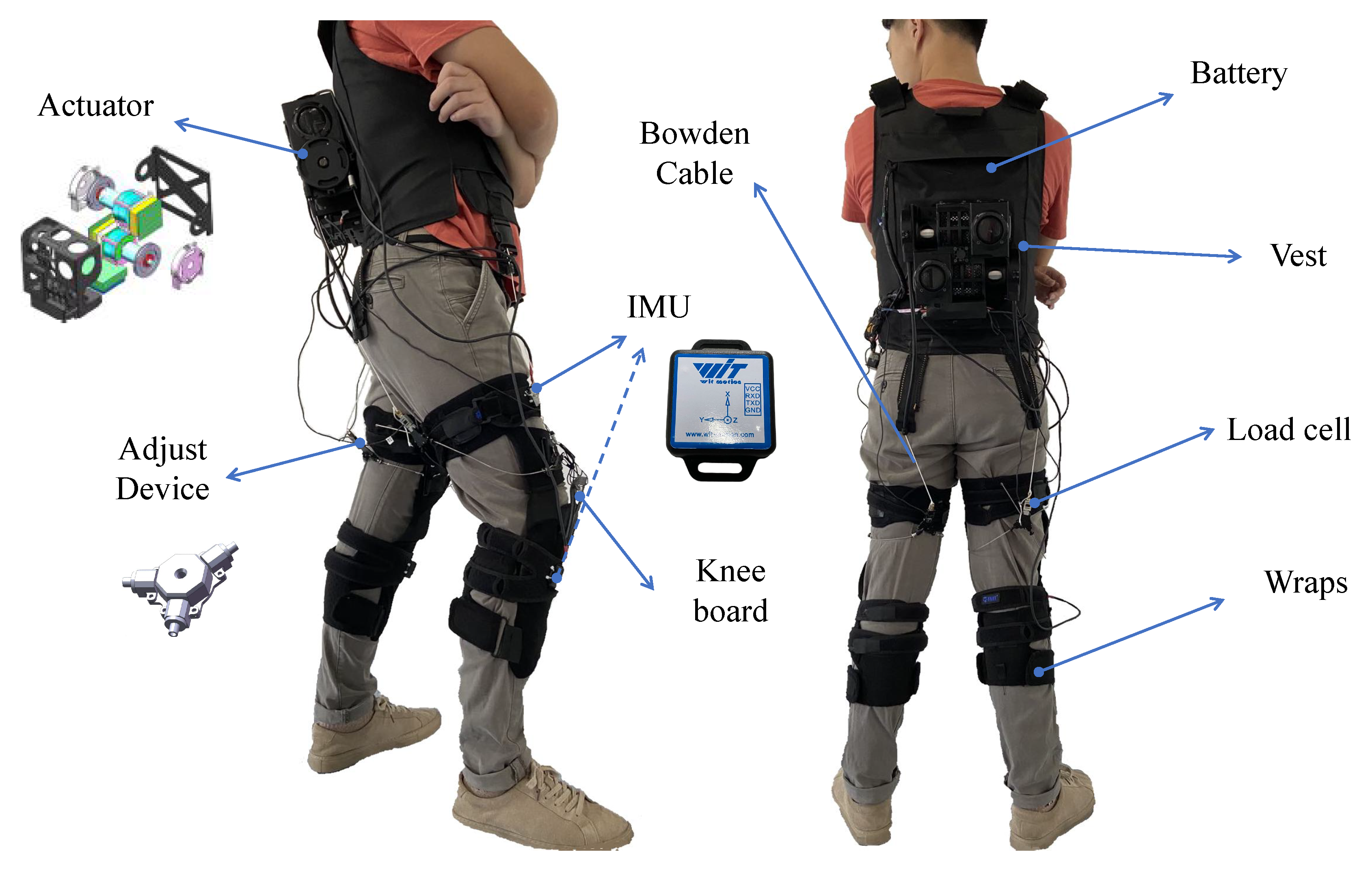
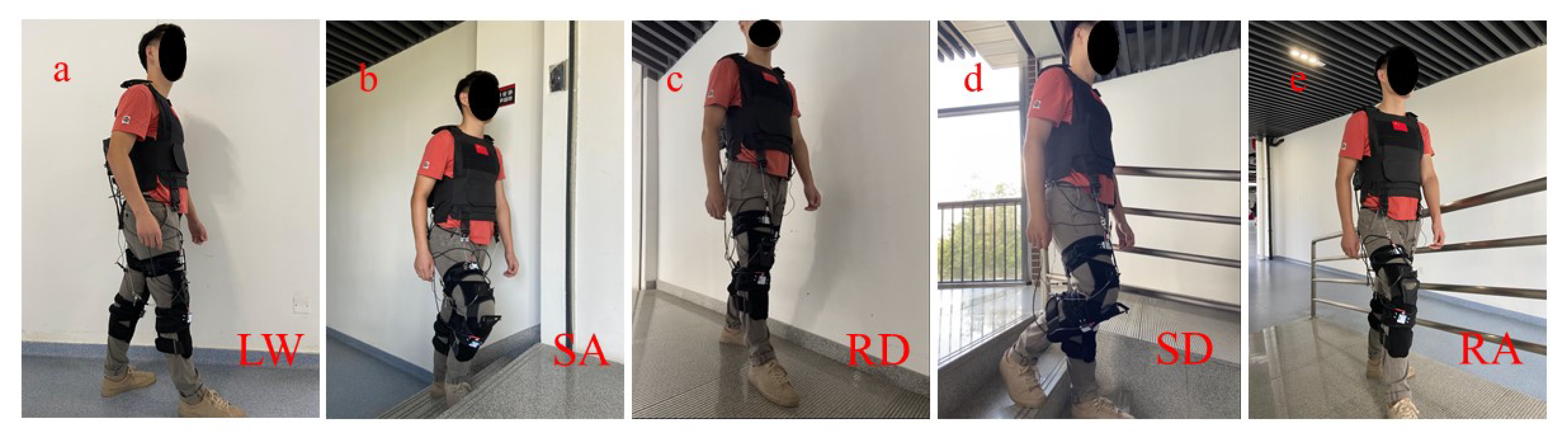
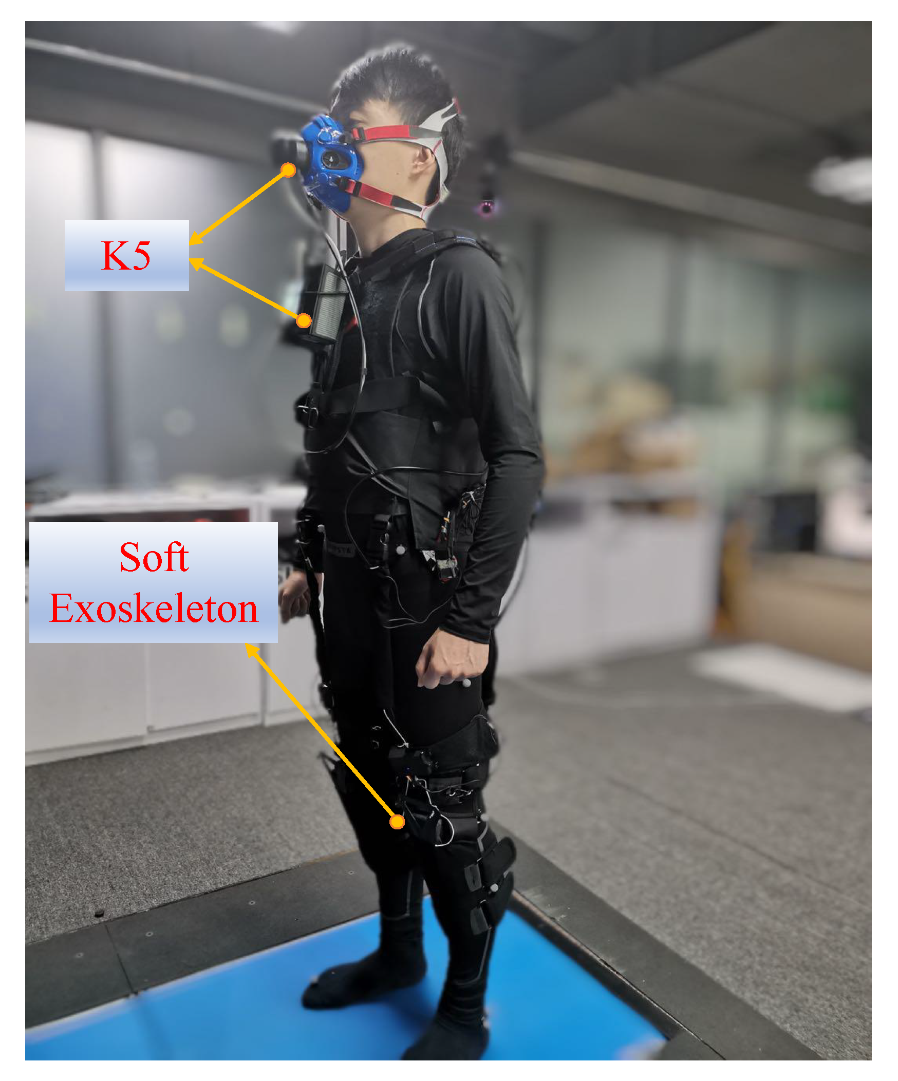
2.1. The Structure of Soft Exoskeleton

In this article, the Shenzhen Institutes of Advanced Technology (SIAT) soft lower limb exoskeleton robot as the research object. It is independently developed by the Shenzhen Institute of Advanced Technology, Chinese Academy of Sciences. Our soft exoskeleton system is composed of six components which are the actuation module, Bowden cable, a Bowden cable adjusting unit, load cells, IMU sensor, and soft wraps (see Figure 1).
The overview of our exoskeleton is shown in Figure 1. The actuator, fixed in the back of the human through a belt, contains the motor, microprocessor, and switch. The end of the Bowden cable is connected to the load cell (GJBLS-WS, Bengbu Zhongcheng Sensor, Bengbu, China), and the other end of the load cell is connected to the wraps through an elastic material. The soft exoskeleton is not interfering with the wearer’s movement when the Bowden cable is slack. The real-time assistance force can be measured by the load cell. The elastic material between the load cell and wraps is used to counteract the significant changes of the force in Bowden cable, and increase the comfort of the soft exoskeleton. The wraps are fixed in the knee joint, which helps to avoid the problem of wraps slapping with assistance. In each leg, the IMU (BWT901CL, Shenzhen wit-motion Technology Co. Ltd., Shenzhen, China, Integrated high-precision Kalman filter attitude fusion algorithm to reduce measurement noise and improve measurement accuracy) and the microprocessor are fixed in the thigh through wraps. The state of the lower limb can be obtained through IMU, and the information of IMU and load cell is transmitted to the main controller through Bluetooth.
As shown in Figure 1, the entire drive module is fixed to the vest. The Bowden cable relates to the leg cover of each leg through the fixed point on the vest, which transmits the force from the motor system to the protective clothing. When the motor rotates inward, the distance between the connection points will be shortened, producing tension on the Bowden cable and acting on the whole protective clothing. Moreover, the initial length of the Bolton cable is adjustable for different wearers. IMU is used to collect real-time motion data of the wearer, such as angle, angular acceleration, and angular velocity. On each leg, two IMUs are respectively installed in the front of the thigh and shin. A load sensor is defined between the anchor cable and the anchor point to monitor force change in real time and return the force data to supply the microcontroller [24]. The exoskeleton consists of a nylon vest with a traction train, two belts wrapped around the test object, and two scaffolds (carbon fiber plate) which transmit traction torque to the knee and femoral joints.
We use two driving modules ADM-15D80-CALT (ADM-15D80-CALT, Techservo, Shenzhen, China). Each driving module includes a brushless motor (MG-1/S 6010, DJI, Shenzhen, China). There are microprocessors (STM32F407, STMicroelectronics, Milano, Italy) that connect the microprocessor with the CAN communication protocol to process IMU and load sensor data, and send the command from the position required for the engine drive device. The system is supplied by a battery of lithium ions capable of 48V and 3ah. As shown in Figure 2, the control system is divided into three parts: perception layer, conversion layer and execution layer. The perception layer mainly receives signals from various mechanical sensors and identifies the human motion intention according to the intention recognition algorithm. In the conversion layer, a parameter optimal iterative learning control (POILC) method proposed by Chen et al. [24] is adopted, which maps the generated motion intention into the corresponding force generation trajectory. Finally, the executive layer controls and drives the flexible exoskeleton according to the force generation trajectory. Therefore, in the control system of flexible lower limb exoskeleton, human motion intention recognition plays an important role.

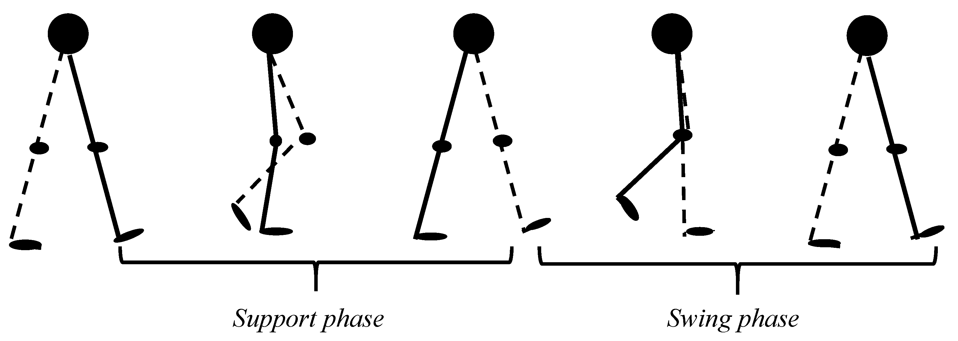
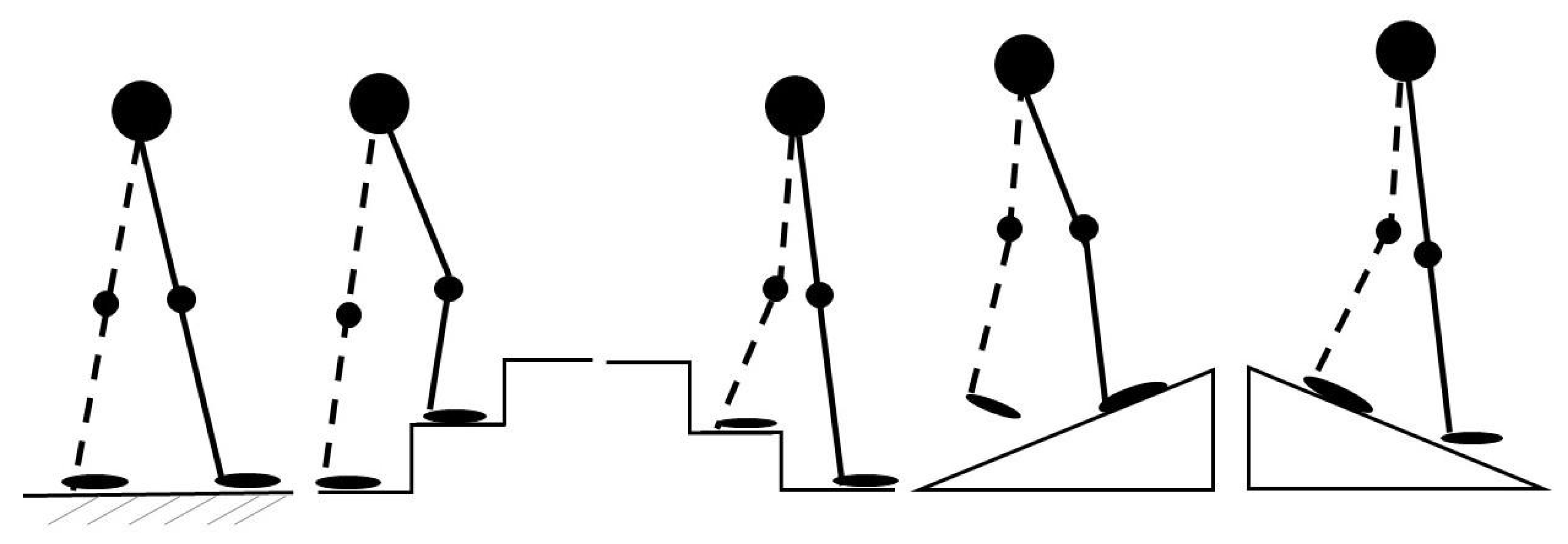
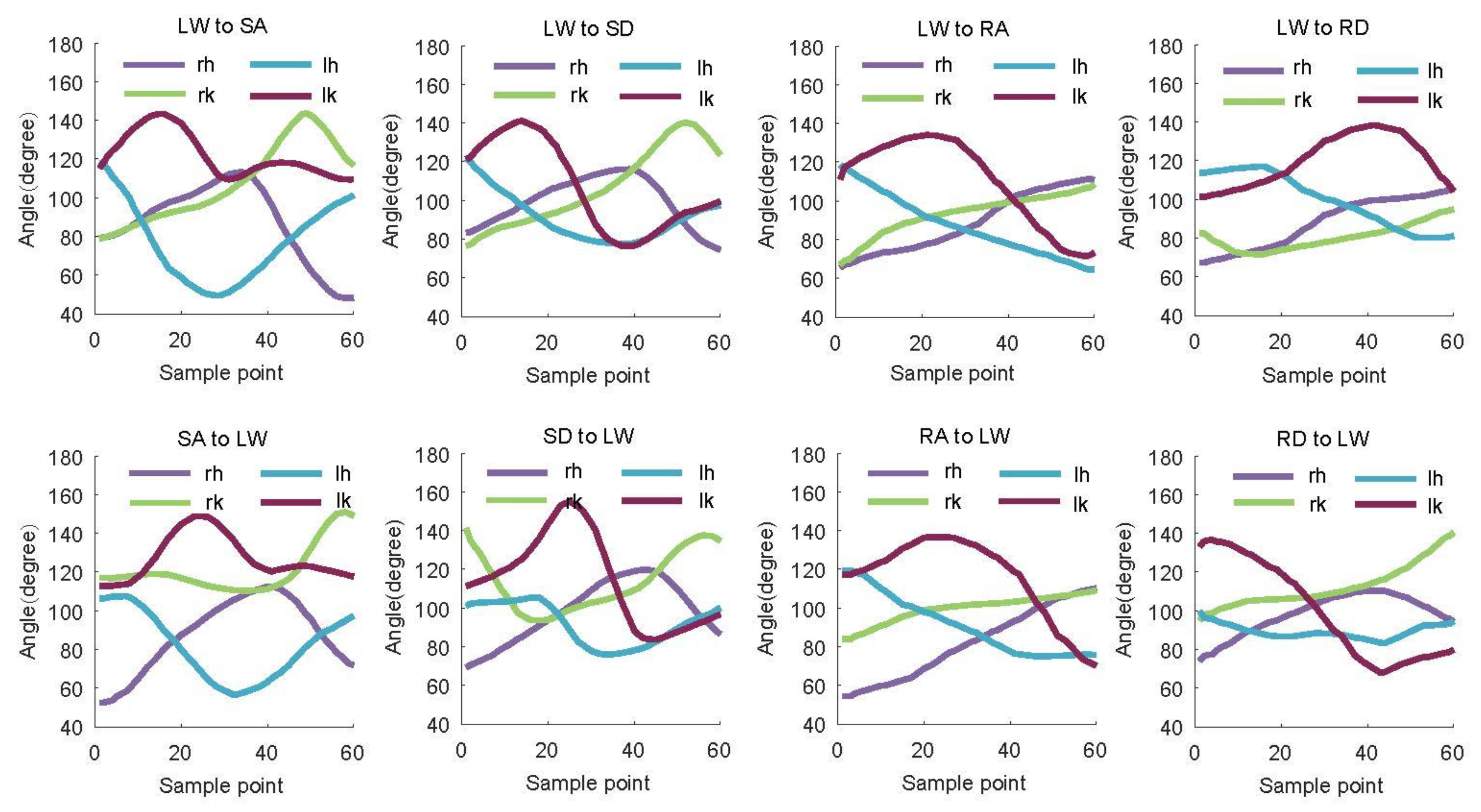
2.2. Analysis of Motion Characteristics

The lower limb movement of the human body has periodicity and regularity. Therefore, the cycle can be defined under flat conditions, starting from the foot impact of a foot to the end of the next foot of the same foot. [12]. Thus, the gait can be divided into support phase and swing phase (see Figure 3).
In this paper, four inertial sensors in front of the big and small legs are installed, as shown in Figure 1. We calibrate the x-axis of the sensors uniformly and horizontally to the left. The angle analysis of hip and knee joints in different terrains is mainly based on the angle of these two joints, relative to the x-axis.
In our daily life, besides walking on the ground, stairs and ramps are the most common terrains. Five kinds of terrains are studied (see Figure 4). In different terrains, the motion information of the hip joint and knee joint is different. While walking on flat ground, the left and right legs regularly switch between the two major phases. The angle and angular velocity of the hip and knee joints change periodically. The process of walking up and downstairs is similar to walking on flat ground, which also has periodicity. In the process of going upstairs, the hip and knee joints are in a state of flexion. With lifting the leg, the flexion angles of the hip joint and knee joint gradually increase. The maximum value of the flexion angle appears in the later stage of the swing phase. While going downstairs, the flexion angle of the knee joint gradually increases in the support phase, reaches the maximum flexion angle in the early swing phase, and gradually extends in the second half of the swing phase. Different terrain can be identified by motion information. Figure 5 shows the changes in hip and knee joint angles in diverse terrain.
When the human body is standing still, the starting angle of the hip and knee joints is about 90 degrees, which may vary slightly from person to person. From standing to walking on the horizontal ground, the first time you lift the right foot, then you start to enter the support phase. The angle of the right leg’s hip joint increases slowly to the peak value and reaches the middle stage of the support phase. At the end of the support phase, the angle of the right leg’s hip joint fell back to the standing state. After that, the right leg’s hip joint angle began to decrease to the minimum value, reached the middle swing phase, and finally returned to 90 degrees in the late swing phase. The whole process is a gait cycle. The hip joint angle of the left leg is a mirror image to the right leg. The angle change of the knee joint will not be described in detail. The gait change of walking on flat ground can be clearly seen from Figure 5.
The change of gait on stairs is similar to that on flat ground, especially the hip joint change, but its peak value is different. The maximum amount of going upstairs is about 110 degrees, while walking on flat ground is about 120 degrees. The curve of the hip joint angle is sinusoidal. However, the knee joint has a small increase in the early stage of swing, and then falls back to the minimum value. For downstairs, the range of knee joint swing is more wider, the hip joint mainly plays a role of supporting body balance, and its swing range is tiny, between 70 and 95 degrees.
It is not difficult to find that the angle change trend of uphill and upstairs is very similar. The difference is that the knee joint drops sharply from the middle stage of support phase to the intermediate stage of swing phase during the uphill process. In contrast, the knee joint first drops to the later stage of support phase, and then goes through a small increase and then decreases until the later stage of the swing phase. During the ascent, the angle of hip and knee joint changes greatly. The knee joint has a broader range of change, while the hip joint is not apparent. Except for the joint angle which is able to be used as a recognition feature, in order to find more in-depth representation by deep learning, we also add angular acceleration and angular velocity as input data.
The angle information used in this paper is directly output by IMU, and there is a 90-degree difference with the actual hip posture angle. Therefore, 90 degrees should be subtracted from the original angle information when compared with the attitude angle obtained by Vicon system dynamic capture in [25]. One-way ANOVA showed that there was no significant difference in F value at the level of a = 0.01. Therefore, the inertial measurement system used in this paper is reliable.
To solve severe delays in the flexible exoskeleton control, we also studied the conversion modes between the five topologies. Continuously moving on the same terrain is defined as steady-state model, and all five types of terrain mentioned above belong to the steady-state model. The motion mode from the initial terrain to another terrain is called the transition mode. The sliding window is used to extract the data corresponding to the steady-state mode, i.e., 100 data points are extracted from the toe off the ground. For the eight transition modes, several frame data are extracted from the conversion step. Figure 6 shows the angle signals of both legs’ sensors with eight transition modes.

3. Identification Method

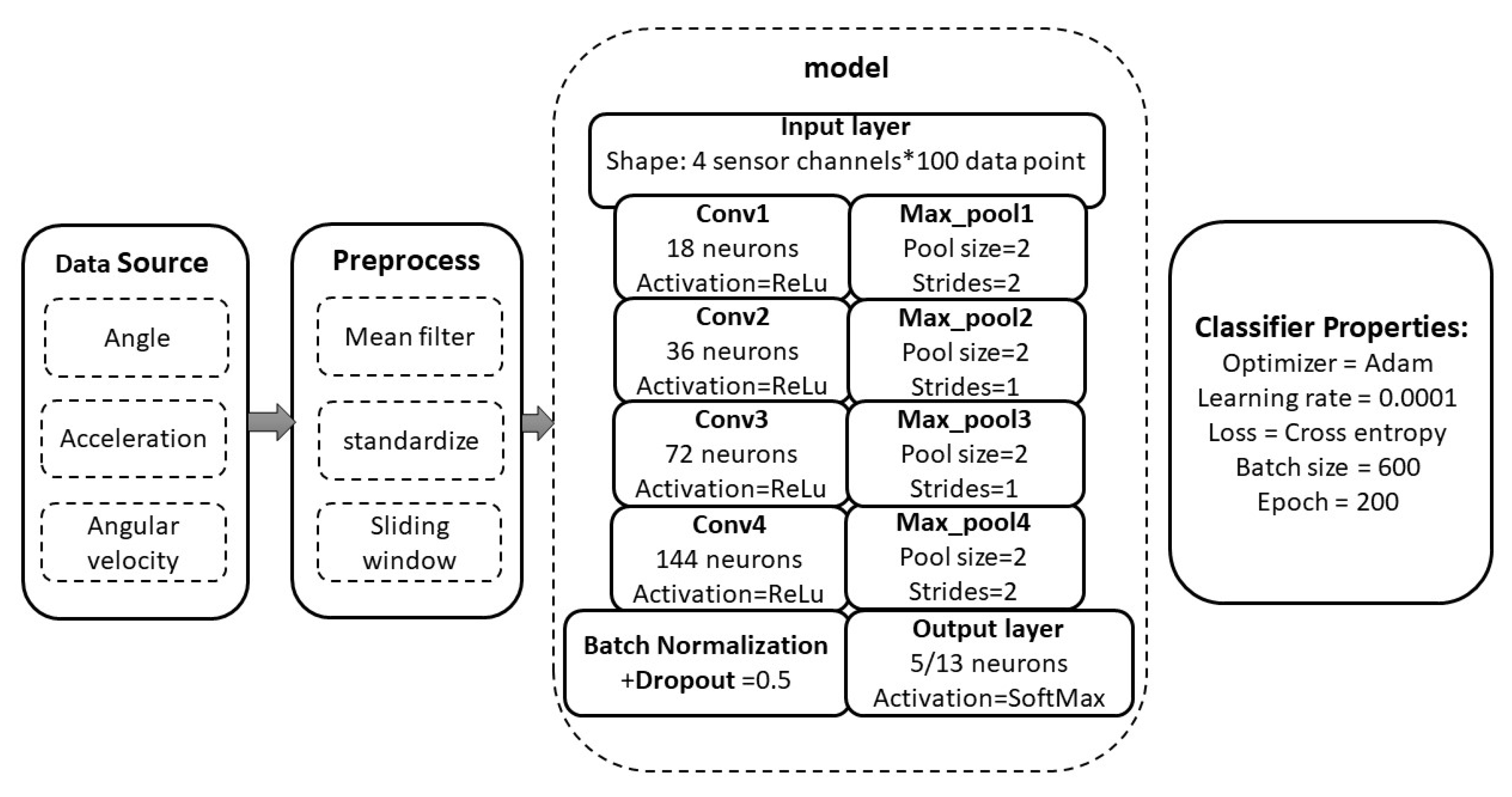
3.1. Gait Data Process

Considering that data loss is inevitable in data acquisition, we first replace the data loss with the values of the previous moment to ensure that the subsequent data are correctly transmitted to the network. We use mean filter with a window length of three for the random noise processing of the original data according to Equation (1).
θ i ( t j ) = 1 3 1 1 θ i ( t j ) , a i ( t j ) = 1 3 1 1 a i ( t j ) , i = r h , l h , r k , l k w i ( t j ) = 1 3 1 1 w i ( t j )
where θ is the joint angle at time t before filtering and θ is the corresponding joint angle after filtering. In the same way, a, a , w, w . Here, i denotes one of the six joints, and j is the tag of a window.
Therefore, the characteristics of the DDLMI model are characterized according to Equation (2):
x = θ i , a i , w i T , i = r h , l h , r k , l k
To make the neural network produce a better effect, we use the following formula to standardize the input vector elements to the range of [ 1 , 1 ] , according to Equation (3):
X θ i = y m a x y m i n X θ i X θ m i n X θ m a x X θ m i n + y m i n X a i = y m a x y m i n X a i X a m i n X a m a x X a m i n + y m i n X w i = y m a x y m i n X w i X w m i n X w m a x X w m i n + y m i n
We normalize the angle, acceleration, and angular velocity, and set y m i n the lower limit to 1 and the upper limit to 1. X θ m i n and X θ m a x represent the minimum and maximum values of the input angle vector, respectively. X a m i n , X a m a x , X w m i n and X w m i n are set in the same way.
Next, we use a sliding window with an overlap of fixed length to segment the data. We move the sliding window from one sampling point to another, then keep a certain proportion of the previous window and move forward the same length. Each window sequence is a training sample. Moreover, each sample carries the history information of the previous sample. In this paper, the window size is set to 100, and the step size is 50.
Concerning labeling, we adopt the method of “one-hot”, that is, in each column vector, except one is 1, the others are 0. All the locomotion modes as expressed by Equation (4).
Level   ground   walking 1 0 0 0 0 , Stair   ascent 0 1 0 0 0 , Stair   descent 0 0 1 0 0 , Ramp   ascent 0 0 0 1 0 , Ramp   descent 0 0 0 0 1 .

3.2. DNN-Based Deep Locomotion Mode Identification Model

In order to obtain a strong correlation between different signal features of four IMUs at different positions, from the perspective of time, a motion pattern recognition method based on deep learning with historical information is proposed. M. Zeng et al. [26] proposed the first important work of human activity recognition using a convolutional neural network. In this paper, the author develops a simple CNN model for accelerometer data. Accelerometer data of each axis of accelerometer data are input into a separate convolution layer, pooling layer, and then connected before the hidden full connection layer is interpreted. With the rise of deep learning networks, many researchers have begun to use a neural network to recognize human movement [27,28,29], which provides a new idea for improving the pose recognition of flexible lower limb exoskeleton.
Since sensor activity data are recorded in time series, it is important to prepare training data according to the request for neural network convolution (CNN). In our proposed DNN-based deep location mode identification model(DDLMI), the data input includes four multi-dimensional channels, including an axis angle (x), two axes (XY) acceleration and two axes (YZ) angular velocity. Before transmitting to the network, we generally perform a series of preprocessing on the original data. Firstly, average filtering is performed for noise filtering, and then the data are normalized to eliminate the adverse effects of singular sampling data, and data is expanded by sliding window algorithm. Finally, data from parallel one-dimensional time series need to be reconstructed in the three-dimensional structure required by DDLMI, including the specific number of one-dimensional neurons, storing the number of memory steps to be processed for each time step and representing different sensor channels. For the architecture shown in Figure 7, we prepared a reformatted matrix of shape: No. of data rows × 100 samples/sequence × 20 features.
The network architecture of this paper is composed of four convolution layers and one layer of full connection. Since Relu activation function can alleviate the problem of overfitting, we add Relu to each layer of the convolution network. In the last full connection layer, we use a dropout layer to randomly discard some neural network units according to the probability of 0.5.
Therefore, the evidence for a locomotion mode is expressed by Equation (5).
f x = w h x t + b h , j = 1 , 2 , 3 N
where x t is the input feature, w h is the weights, b h is the bias, and N is the total number of all motion modes. In this paper, we discuss five classical steady-state modes, eight transition modes, a total of 13 motion modes, so N = 13 .
Finally, we use SoftMax function to calculate the probability of the model; the SoftMax function as expressed by Equation (6).
y i = softmax   f x = e f x j = 0 N e f x
In the process of training the model, we must give the definition of error, namely loss function. “Cross-entropy” is used for calculating the loss in this paper. Furthermore, it is defined by Equation (7).
l o s s = 1 N i = 1 N 1 2 e x p ( l o g ( σ 2 ) ) y i y i 2 + 1 2 l o g ( σ 2 ( x i ) )
where y i is our predicted value, and y i is the true value. In the loss function, this σ 2 ( x i ) describes the accidental uncertainty of the model on the data x i , that is, the variance of the data.
Finally, Adam optimization algorithm is selected to adjust the network parameters to minimize the loss and improve network performance.

3.3. Performance Evaluation

To verify our proposed DDLMI method’s performance, we need to determine an evaluation index. In this paper, the locomotion period was divided into a steady locomotion period and a locomotion transition period. For the steady-state mode, the critical point is to identify the target terrain. As for the transition mode, we are more concerned about whether it can be recognized earlier. As a result, they were assessed separately.
1.
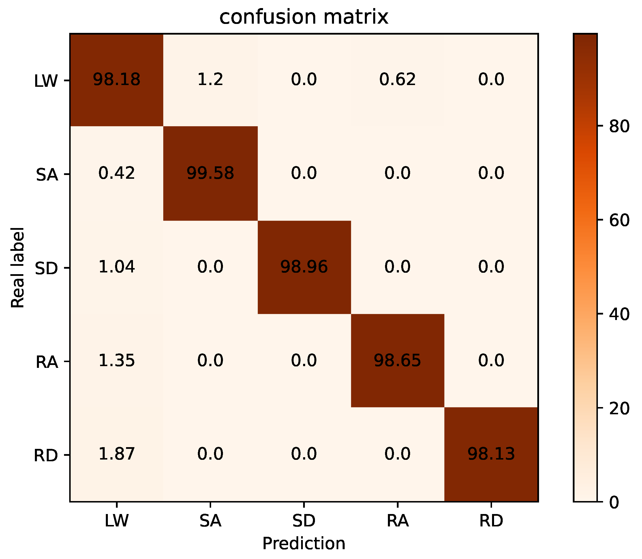
Steady Locomotion Period: Normally, the identification success rate (ISR) is used for evaluating the accuracy of a classification [7], which is given Equation (8).
ISR = N correct N total
where N correct is the number of correct identification data while N total is the total number of test events in the experiment.
To better illustrate the identification performance and quantify the error distribution, the confusion matrix is defined Equation (9).
C M = c 11 c 12 c 13 c 14 c 15 c 21 c 22 c 23 c 24 c 25 c 31 c 32 c 33 c 34 c 35 c 41 c 42 c 43 44 c 45 c 51 c 52 c 53 c 54 c 55
The element of the confusion matrix is expressed by Equation (10).
c i j = N i j N i
where N i j is the number of samples that terrain i wrongly recognized as terrain j, and N i is the total number of terrains i. The elements on the diagonal of the confusion matrix are the recognition accuracy. At the same time, those elements on the non-diagonal refer to the error rates.
2.
Locomotion Transition Period: In order to judge whether the conversion pattern recognition is timely, we adopt the critical moment of [7] proposed, which refers to the moment when the user starts to change the current locomotion mode. The identification delay can be expressed by Equation (11).
D I = T i T c T 100 %
where T i is the moment when locomotion transition is identified, T c is the critical moment, and T is the average time of a gait cycle.

4. Experiments Results and Analysis

4.1. Model Validation

4.1.1. Subjects and Experiment Protocol

Seven healthy subjects in the experiments (six males and one female, 24 ± 5 years old, 62 ± 9 kg weight, and 172 ± 8 cm height) were provided with informed consent. According to the guidelines, all participants wore the flexible lower limb exoskeleton system and then performed the experiment according to the requirements.
The experiment consists of three parts. Firstly, in order to train the model, we need to collect sensor data. Through the second part of the feature analysis, we use four inertial sensors to place the subjects’ left and right thighs and the center of the shin to collect data. The data are recorded at a sampling frequency of 50 Hz, including accelerometer and gyroscope measurements. Each subject was required to repeat the steady-state movement mode at a steady speed 30 times, including eight switching modes: LW to SA, LW to SD, SA to LW, SD to LW, LW to RA, LW to RD, RA to LW and RD to LW. The experimenter is responsible for collecting and recording the time series data generated by the sensor. Each subject’s data are recorded separately, and each different gait behavior needs to be labeled correspondingly. In the second part, the model parameters are determined by training the model. In the process of model training, the test set is completely separated from the training data set. In addition, to avoid using training data to overfit the model, 20% of the training data set is reserved as the verification set [30]. When training the model, we set batch size = 600, epoch = 200, and each training epoch takes 1.26 ms. When the epoch is about 130, the train loss tends to be balanced. Using the TensorFlow framework, the system runs on a laptop with a processor of 1.8 GHz and a memory size of 8 GB. The compiler environment is Python 3.7. In the last part, the accuracy and real-time performance of the model are verified. The subjects were asked to walk at a uniform speed on different terrains, including all-terrain and movement transitions shown in Figure 8. The height of the stairs in the experimental scene is 16 cm, while the slope angle of the ramp is 10 degrees.

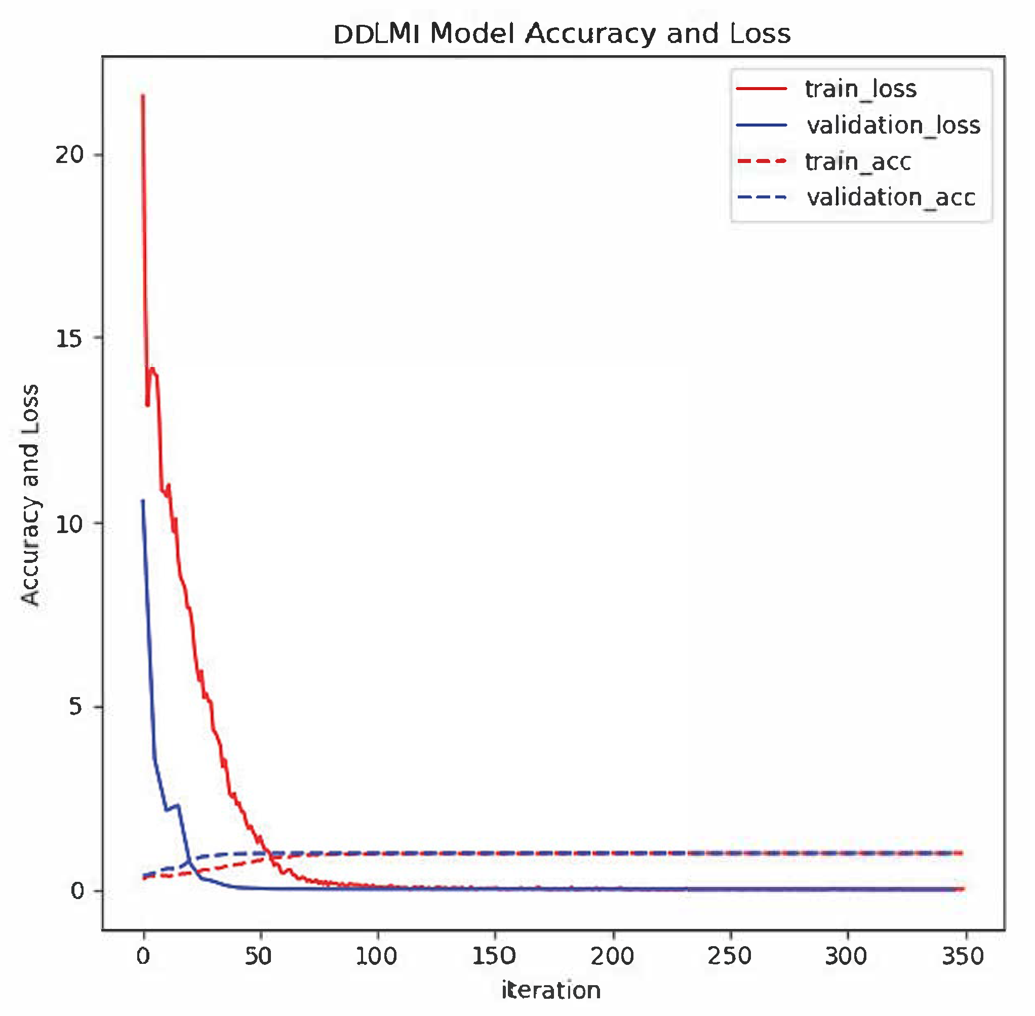
4.1.2. DDLMI Identification Performance

In the model training stage, the loss and accuracy of network training and verification can be obtained from Figure 9. After about 50 iterations, the loss functions of training and verification are infinitely close to zero, and the accuracy of both approaches 100%. This shows that the model has a good fitting effect. In the offline testing phase, the recognition accuracy of 7 subjects under different terrain conditions is shown in Table 1. The lowest recognition rate is 96.07%, and the highest is 100%. In the five terrains, ascending stairs and descending stairs have the best recognition rate. In these two cases, the hip and knee of both legs extend more widely, different from other terrains. The recognition of flat ground is the worst. The average classification rate of the five terrains is as high as 98.96%, which is in line with the actual requirements. Moreover, the five steady states confusion matrix is given in Figure 10. From the confusion matrix, it is not difficult to find that walking up and down the slope is easy to be confused with walking on the ground. The main reason is that walking upslope and walking downslope are similar, especially when the angle of slope is small. The second point is that on the initial uphill and downhill, the smaller the stride, the easier it is to be recognized as walking on flat ground. In addition, during the conversion, the last step is to walk on the ground, which may also be inaccurate. Generally speaking, the probability of confusion is within the acceptable range, which is in line with the actual situation, so the probability of correct identification is still satisfying.
In this paper, we consider eight conversion modes among five kinds of terrain: LW to SA, LW to SD, SA to LW, SD to LW, LW to RA, LW to RD, RA to LW and RD to LW. The average delay rates of these transition modes are listed in Table 2. The DDLMI method can identify the next motion mode before the forelegs touch the ground. According to the definition, the results show that the recognition delay rate is relatively small in horizontal ground walking and uphill and downhill, because the gait curves of uphill and downhill are similar to that of horizontal walking. However, for the conversion between walking up and down stairs and walking horizontally, the recognition delay rate is low, which shows that this method has a significant recognition effect for up and down stairs and horizontal walking.

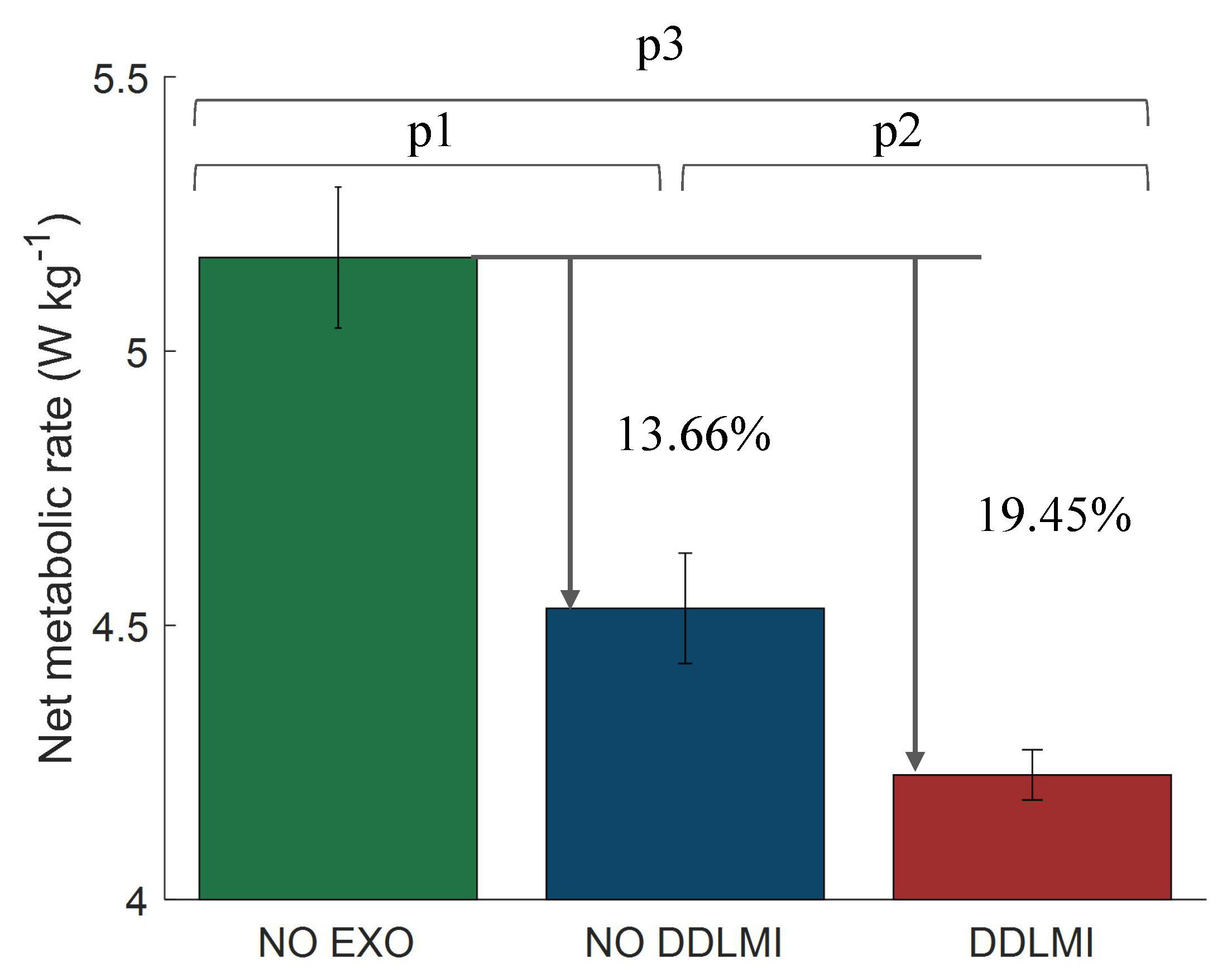
4.2. Metabolic Cost Test

4.2.1. Experimental Setup and Protocol

In the field of exoskeleton, net metabolic costs are often used to support its efficiency to evaluate. Six healthy adult males (24 ± 5 years old, 68 ± 8 kg weight, and 177 ± 6 cm height) participated in the experiment for metabolic rate. We conducted the experiment indoors at a speed of 4 km/h and temperature of 26 C. To measure the metabolism, concentration and volume of expired lung gas were measured using a gas analyser (COSMED K5, Rome, Italy) to record the concentration and volume of the exhaled pulmonary gas, which is mainly composed of carbon dioxide and oxygen. The metabolic rate can also be calculated using with Brockway equation modified [31]. For example, Equation (12).
Δ H = c 1 V O 2 + c 2 V C O 2
where coefficients c 1 and c 2 are 16.89 kJ/L and 4.84 kJ/L, respectively, and Δ H is the energy rate (kJ/s). During the migration process, carbon dioxide and oxygen sacrifice data were collected during the stabilisation phase.
It is more beneficial to reduce oxygen consumption by exerting different forces according to different terrains [24]. In [24], the experimental methods and steps of applying different forces to different terrains are introduced in detail. This paper will not repeat the steps of the experiment, the only thing that needs to be explained is that in the whole experiment process, the terrain recognition method proposed in this paper is added in this experiment, and the fixed terrain in [24] is changed into randomly switching terrain. The experimental progress is shown in Figure 11.

4.2.2. Metabolic Reduction by DDLMI

By adding the method of terrain recognition, the exoskeleton can give more accurate assistance in different terrain, and the assist performance of exoskeleton is improved. A comparative experiment was carried out on different terrains. The effect of DDLMI method on metabolic rate reduction is shown in Figure 12. The results show that the algorithm improves the flexible exoskeleton through adaptive terrain. After applying the DDLMI method, the net metabolism is reduced greatly. The net metabolism was reduced by 13.66% without DDLMI and 19.45% without DDLMI. Compared with the unrecognized method, the net metabolism was reduced by 5.79%, which improved the auxiliary effect of the flexible lower extremity exoskeleton.

5. Discussion

This article first introduces the basic structure of the SIAT flexible exoskeleton and its control strategy, and then determines the characteristics of the motion mode by analyzing the gait in five different motion modes. Finally, a novel DDLMI method is proposed to identify the movement intention of the flexible exoskeleton. This method can transfer parameters before the next movement mode is switched, so that the exoskeleton can change the state parameters in advance to adapt to the new mode. Thereby, the control performance of the flexible lower extremity exoskeleton system is greatly improved, and the exoskeleton can switch naturally and seamlessly between multiple movement modes according to the human movement intention.
In terms of time, the method in this paper attempts to predict the next movement mode before the movement mode has occurred, so as to better realize the recognition of the intention. The comparative experiment and analysis are shown in Table 3.
When only five steady-state modes are considered, the recognition rate of the method in this paper is as high as 97.64%, which is slightly higher than the literature [15,32]. In addition, most literature [15,32,34] uses multiple types of sensors, which need to solve the problem of data fusion. For example, inertial measurement unit plus pressure sensor, etc. In this paper, a single sensor is used. Before the mode conversion, the timing sequence of the two-side sensor is collected for recognition, and the recognition result reaches 97.64%. Therefore, the method in this paper does not need to consider the fusion of various types of sensors, such as mechanical sensors, pressure sensors and multimodal data signals, reducing the complexity of the algorithm, and achieves recognition accuracy, that is not lower than, or is even better than traditional methods. Research studies [7] including this paper use a single sensor IMU, but the number of sensors is more than this paper. In terms of recognition rate, this article is second only to literature [7], but the delay rate of the DDLMI recognition method proposed in this article is the lowest overall. However, in [33], which also uses convolutional neural network for gait recognition, it is still slightly lower in recognition accuracy than the method in this paper, and it uses more IMUs. It can be seen that this method is not only better than traditional machine learning (SVM, HMM) methods, but also slightly better than similar neural networks. In [35], fixed cameras were used to capture the sequence image of human body movement, and a neural network was finally used for recognition, with the recognition accuracy up to 95%, slightly lower than the method in this paper. Compared with the recognition of gait by optical system which is confined to indoor sports, the method in this paper is applied to a wider range of scenarios, and can be recognized even in outdoor sports. In order to further verify the performance and effectiveness of our system, we compared the precision with the dynamic capture system in Table 4.
Although our recognition accuracy is slightly lower than that of the motion capture system, we used the minimum number of IMUs based on the minimum rule, and did not use the information of foot pressure, and obtained the recognition effect of 97.64%. In addition, fewer sensors are more suitable for wearable flexible exoskeletons. Therefore, all in all, the accuracy and robustness of the method in this paper are relatively good, and it has engineering application value in exoskeleton and prosthesis.

6. Conclusions

In this paper, the DDLMI method for real-time terrain recognition based on a single sensor is proposed. With the input of the original data of accelerometer and gyroscope, the average recognition accuracy of the five typical motion patterns was 97.64%, and the average recognition delay was 23.97% of a gait cycle. The results of continuous terrain recognition show that this method can run online in real time. Moreover, it is proven that the net metabolism of walking on different terrains is reduced by 5.79% compared with that without the recognition method, which can improve the assist effect of the flexible lower limb exoskeleton. Therefore, the parameters can be transferred in advance before the motion mode is converted, so as to adjust the control parameters of the flexible exoskeleton in time and recognize the human motion intention better. Using a single sensor can reduce the complexity of data processing to a certain extent. Compared with the traditional intention recognition methods, we use a deep learning model, which can directly extract deeper features from the original data without manual intervention. This study’s significance is that it can make the flexible exoskeleton control system change the related parameters of the lower limbs in advance and switch to different terrain modes seamlessly, which helps the wearer achieve more stable and smooth walking. This provides a new idea for the prediction and recognition of the movement intention of a flexible exoskeleton.

Author Contributions

Conceptualization, L.Z. and Z.W; methodology, L.Z.; software, L.Z.; validation, L.Z., Z.W. and Y.Z.; formal analysis, L.Z., Z.N. and W.C.; investigation, L.Z. and C.C.; resources, C.C.; data curation, L.Z. and Y.Z; writing—original draft preparation, L.Z.; writing—review and editing, Y.L., L.Z. and Z.W.; visualization L.Z., Z.W. and Y.Z.; supervision, X.W. and C.C.; project administration, X.W. and C.C.; funding acquisition, X.W. and C.C. All authors have read and agreed to the published version of the manuscript.

Funding

This research was funded by the Natural Science Foundation of China (U1913207), the Natural Science Foundation of Guangdong Province, China (2019A1515010782), Science Technology and Innovation Committee of Shenzhen Municipality (SZSTI) Fundamental Research Project under Grant (JCYJ20180302145539583), Shenzhen Technology Research Project (JSGG20180507182901552), Guangdong Basic and Applied Basic Research Foundation (2019A1515110576), Shandong Province Science and Technology Projects (2018CXGC0909), Jinan Science and Technology Project (2019GXRC048).

Acknowledgments

The authors would like to thank all subjects who participated in experiments and the members of SIAT exoskeleton team.

Conflicts of Interest

The authors declare no conflict of interest.

Abbreviations

The following abbreviations are used in this manuscript:
IMUInertial measurement unit
DDLMIDNN-based deep locomotion mode identification
ISRIdentification success rate
LWLevel-ground walking
SAStair ascent
SDStair decent
RARamp ascent
RDRamp decent

References

  1. Chen, C.; Zheng, D.; Peng, A.; Wang, C.; Wu, X. Flexible design of a wearable lower limb exoskeleton robot. In Proceedings of the 2013 IEEE International Conference on Robotics and Biomimetics (ROBIO), Shenzhen, China, 12–14 December 2013. [Google Scholar]
  2. Viteckova, S.; Kutilek, P.; Jirina, M. Wearable lower limb robotics: A review. Biocybern. Biomed. Eng. 2013, 33, 96–105. [Google Scholar] [CrossRef]
  3. Xu, T.; Guan, Y.; Liu, J. Image-Based Visual Servoing of Helical Microswimmers for Planar Path Following. IEEE Trans. Autom. Sci. Eng. 2020, 17, 325–333. [Google Scholar] [CrossRef]
  4. Xu, T.; Yu, J.; Vong, C. Dynamic Morphology and Swimming Properties of Rotating Miniature Swimmers with Soft Tails. IEEE ASME Trans. Mechatron. 2019, 24, 924–934. [Google Scholar] [CrossRef]
  5. Wu, X.; Liu, J.; Huang, C. 3-D Path Following of Helical Microswimmers With an Adaptive Orientation Compensation Model. IEEE Trans. Autom. Sci. Eng. 2020, 17, 823–832. [Google Scholar] [CrossRef]
  6. Joshi, D.; Nakamura, B.H.; Hahn, M.E. High energy spectrogram with integrated prior knowledge for EMG-based locomotion classification. Med. Eng. Phys. 2015, 37, 518–524. [Google Scholar] [CrossRef] [PubMed]
  7. Wang, C.; Wu, X.; Ma, Y.; Wu, G.; Luo, Y. A Flexible Lower Extremity Exoskeleton Robot with Deep Locomotion Mode Identification. Complexity 2018, 2018, 5712108. [Google Scholar] [CrossRef]
  8. Eilenberg, M.F.; Geyer, H.; Herr, H. Control of a Powered Ankle–Foot Prosthesis Based on a Neuromuscular Model. IEEE Trans. Neural Syst. Rehabil. Eng. 2010, 18, 164–173. [Google Scholar] [CrossRef]
  9. Peng, Z.; Cao, C.; Huang, J.; Pan, W. Human Moving Pattern Recognition toward Channel Number Reduction Based on Multipressure Sensor Network. Int. J. Distrib. Sens. Netw. 2013, 9, 510917. [Google Scholar] [CrossRef] [Green Version]
  10. Long, Y.; Du, Z.J.; Wang, W.D.; Zhao, G.Y.; Xu, G.Q.; He, L.; Mao, X.W.; Dong, W. PSO-SVM-Based Online Locomotion Mode Identification for Rehabilitation Robotic Exoskeletons. Sensors 2016, 16, 1408. [Google Scholar] [CrossRef] [Green Version]
  11. Shen, B.; Li, J.; Bai, F.; Chew, C.M. Motion intent recognition for control of a lower extremity assistive device (LEAD). In Proceedings of the IEEE International Conference on Mechatronics & Automation, Takamatsu, Japan, 4–7 August 2013. [Google Scholar]
  12. Duc, N.N.; Trong, B.D.; Huu, T.P.; Gu-Min, J. Classification of Five Ambulatory Activities Regarding Stair and Incline Walking Using Smart Shoes. IEEE Sens. J. 2018, 18, 5422–5428. [Google Scholar]
  13. Chen, B.; Zheng, E.; Fan, X.; Liang, T. Locomotion mode classification using a wearable capacitive sensing system. IEEE Trans. Neural Syst. Rehabil. Eng. 2013, 21, 744–755. [Google Scholar] [CrossRef] [PubMed]
  14. David Li, Y.; Hsiaowecksler, E.T. Gait mode recognition and control for a portable-powered ankle-foot orthosis. In Proceedings of the 2013 IEEE 13th International Conference on Rehabilitation Robotics (ICORR), Seattle, WA, USA, 24–26 June 2013. [Google Scholar]
  15. Liu, Z.; Lin, W.; Geng, Y.; Yang, P. Intent pattern recognition of lower-limb motion based on mechanical sensors. IEEE/CAA J. Autom. Sin. 2017, 4, 651–660. [Google Scholar] [CrossRef]
  16. Zhang, F.; Fang, Z.; Liu, M.; Huang, H. Preliminary design of a terrain recognition system. In Proceedings of the 2011 Annual International Conference of the IEEE Engineering in Medicine and Biology Society, Boston, MA, USA, 30 August–3 September 2011. [Google Scholar]
  17. Chen, B.; Zheng, E.; Wang, Q. A Locomotion Intent Prediction System Based on Multi-Sensor Fusion. Sensors 2014, 14, 12349–12369. [Google Scholar] [CrossRef] [PubMed] [Green Version]
  18. Huang, H.; Zhang, F.; Hargrove, L.J.; Dou, Z.; Rogers, D.R.; Englehart, K.B. Continuous Locomotion-Mode Identification for Prosthetic Legs Based on Neuromuscular–Mechanical Fusion. IEEE Trans. Biomed. Eng. 2011, 58, 2867–2875. [Google Scholar] [CrossRef] [PubMed] [Green Version]
  19. Ma, Y.; Wu, X.; Wang, C.; Yi, Z.; Liang, G. Gait Phase Classification and Assist Torque Prediction for a Lower LimbExoskeleton System Using Kernel Recursive Least-Squares Method. Sensors 2019, 19, 5449. [Google Scholar] [CrossRef] [PubMed] [Green Version]
  20. Ren, H.; Shang, W.; Li, N.; Wu, X. A fast parameterized gait planning method for a lower-limb exoskeleton robot. Int. J. Adv. Robot. Syst. 2020, 17. [Google Scholar] [CrossRef] [Green Version]
  21. Yuan, K.; Parri, A.; Yan, T.; Wang, L.; Vitiello, N. A realtime locomotion mode recognition method for an active pelvis orthosis. In Proceedings of the 2015 IEEE/RSJ International Conference on Intelligent Robots and Systems (IROS), Hamburg, Germany, 28 September–3 October 2015. [Google Scholar]
  22. Zheng, E.; Wang, L.; Wei, K.; Wang, Q. A Noncontact Capacitive Sensing System for Recognizing Locomotion Modes of Transtibial Amputees. IEEE Trans. Biomed. Eng. 2014, 61, 2911–2920. [Google Scholar] [CrossRef]
  23. Yuan, K.; Wang, Q.; Wang, L. Fuzzy-Logic-Based Terrain Identification with Multisensor Fusion for Transtibial Amputees. IEEE/ASME Trans. Mechatron. 2015, 20, 618–630. [Google Scholar] [CrossRef]
  24. Chen, C.; Zhang, Y.; Li, Y.; Wang, Z.; Wu, X. Iterative Learning Control for a Soft Exoskeleton with Hip and Knee Joint Assistance. Sensors 2020, 20, 4333. [Google Scholar] [CrossRef]
  25. Mcintosh, A.S.; Beatty, K.T.; Dwan, L.N.; Vickers, D.R. Gait dynamics on an inclined walkway. J. Biomech. 2006, 39, 2491–2502. [Google Scholar] [CrossRef]
  26. Ming, Z.; Le, T.N.; Bo, Y.; Mengshoel, O.J.; Zhang, J. Convolutional Neural Networks for Human Activity Recognition using Mobile Sensors. In Proceedings of the Sixth International Conference on Mobile Computing, Applications and Services (MobiCASE 2014), Austin, TX, USA, 6–7 November 2014. [Google Scholar]
  27. Lara, O.D.; Labrador, M.A. A Survey on Human Activity Recognition using Wearable Sensors. IEEE Commun. Surv. Tutor. 2013, 15, 1192–1209. [Google Scholar] [CrossRef]
  28. Ronao, C.A.; Cho, S.B. Human activity recognition with smartphone sensors using deep learning neural networks. Expert Syst. Appl. 2016, 59, 235–244. [Google Scholar] [CrossRef]
  29. Cho, H.; Sang, Y. Divide and Conquer-Based 1D CNN Human Activity Recognition Using Test Data Sharpening. Sensors 2018, 18, 1055. [Google Scholar]
  30. Zebin, T.; Sperrin, M.; Peek, N.; Casson, A.J. Human activity recognition from inertial sensor time-series using batch normalized deep LSTM recurrent networks. In Proceedings of the 2018 40th Annual International Conference of the IEEE Engineering in Medicine and Biology Society (EMBC), Honolulu, HI, USA, 17–21 July 2018; pp. 1–4. [Google Scholar]
  31. Brockway, J.M. Derivation of formulae used to calculate energy expenditure in man. Hum. Nutr. Clin. Nutr. 1987, 41, 463–471. [Google Scholar] [PubMed]
  32. Young, A.J.; Simon, A.M.; Fey, N.P.; Hargrove, L.J. Intent Recognition in a Powered Lower Limb Prosthesis Using Time History Information. Ann. Biomed. Eng. 2013, 42, 631–641. [Google Scholar] [CrossRef]
  33. Omid, D.; Mojtaba, T.; Raghvendar, C.V. IMU-Based Gait Recognition Using Convolutional Neural Networks and Multi-Sensor Fusion. Sensors 2017, 17, 2735. [Google Scholar]
  34. Zheng, E.; Wang, Q. Noncontact Capacitive Sensing-Based Locomotion Transition Recognition for Amputees With Robotic Transtibial Prostheses. IEEE Trans. Neural Syst. Rehabil. Eng. 2016, 25, 161–170. [Google Scholar] [CrossRef]
  35. Hawas, A.R.; El-Khobby, H.A.; Abd-Elnaby, M.; Abd El-Samie, F.E. Gait identification by convolutional neural networks and optical flow. Multimed. Tools Appl. 2019, 78, 25873–25888. [Google Scholar] [CrossRef]
  36. Yuan, Q.; Chen, I.M.; Lee, S.P. SLAC: 3D localization of human based on kinetic human movement capture. In Proceedings of the 2011 IEEE International Conference on Robotics and Automation (ICRA), Shanghai, China, 9–13 May 2011. [Google Scholar]
Figure 1. The system overview is showing the structure of the soft exoskeleton and the position of its every part.
Electronics 09 02176 g001
Figure 2. Control strategy of flexible exoskeleton.
Electronics 09 02176 g002
Figure 3. Gait cycle.
Electronics 09 02176 g003
Figure 4. Five classic terrains.
Electronics 09 02176 g004
Figure 5. The changes in hip and knee joint angles in diverse terrain. LW (Level ground walking), SA (Stair ascent), SD (Stair descent), RA (Ramp ascent), RD (Ramp descent). rh (right hip), rk (right knee), lh (left hip) and lk (left knee).
Electronics 09 02176 g005
Figure 6. The angle signals of both legs sensor with eight transition modes.
Electronics 09 02176 g006
Figure 7. The structure of the motion recognition method with historical information based on deep learning.
Electronics 09 02176 g007
Figure 8. The testers wear a flexible lower-limb exoskeleton to test the continuous terrain motion recognition. (a) LW (Level ground walking), (b) SA (Stair ascent), (c) SD (Stair descent), (d) RA (Ramp ascent), (e) RD (Ramp descent).
Electronics 09 02176 g008
Figure 9. Average training and validation set accuracy performance over 50 iterations for DDLMI model.
Electronics 09 02176 g009
Figure 10. Confusion matrix of the steady locomotion period.
Electronics 09 02176 g010
Figure 11. The subjects wore exoskeletons and walked on five different terrains. The Bowden cable driven by a motor assisted different forces in different terrain. The metabolic rate is measured through K5.
Electronics 09 02176 g011
Figure 12. The metabolic reduction when walking on different terrains. The NO EXO, NO DDLMI, and DDLMI present the case of not wearing soft exoskeleton, and wearing exoskeleton with and without the DDLMI method. p1, p2, and p3 are the results of two-side t-tests, which are 0.0015, 0.009, and 0.0002, respectively.
Electronics 09 02176 g012
Table 1. The recognition accuracy of five different terrains.
ExperimenterLWSASDRARD
Subject 196.14%98.15%99.03%97.20%97.03%
Subject 296.36%99.42%98.96%98.05%96.57%
Subject 396.78%96.98%99.24%97.78%98.05%
Subject 497.25%96.25%100%96.42%96.34%
Subject 596.22%100%97.89%96.78%96.27%
Subject 697.06%100%98.09%99.01%97.36%
Subject 796.21%99.86%99.56%96.34%96.07%
Average96.57%98.66%98.96%97.36%96.67%
Table 2. Identification delay of locomotion transition.
Conversion ModeIdentification Delay (Percent of One Gait Cycle)
LW to SA8.28%
LW to SD3.96%
LW to RA13.54%
LW to RD16.72%
SA to LW9.12%
SD to LW13.02%
RA to LW12.38%
RD to LW15.67%
Average23.97%
Table 3. Comparison of the methods and experimental results, where acc, gyr and pre represent accelerometer, gyroscope and pressure sensors, respectively.
ResearchSensorSignal CharacteristicsClassifier D I ISR
Liu [15]1 acc, 1 gyr, 2 preICCHMM 95.8%
Young [32]1 IMU, 1 preMean, Std, Max, MinDBN 94.7%
Wang [7]6 IMUICCLSTM30%98.3%
Zheng [22]2 acc, 2 gyr, 1 preMean, Std, etcSVM + QDA 94.9%
Omid [33]5 IMUICCDCNN 97.06%
This work4 IMUICCDDLMI23.97%97.64%
Table 4. Comparison with motion capture system
SystemNumber of IMUNumber of Plantar PressureISR
Kinetic Human Movement Capture [36]8298%
This work4097.64%
Publisher’s Note: MDPI stays neutral with regard to jurisdictional claims in published maps and institutional affiliations.

