Research on Simplified Model of AC/DC Hybrid Microgrid for Fault Analysis


Abstract
:1. Introduction
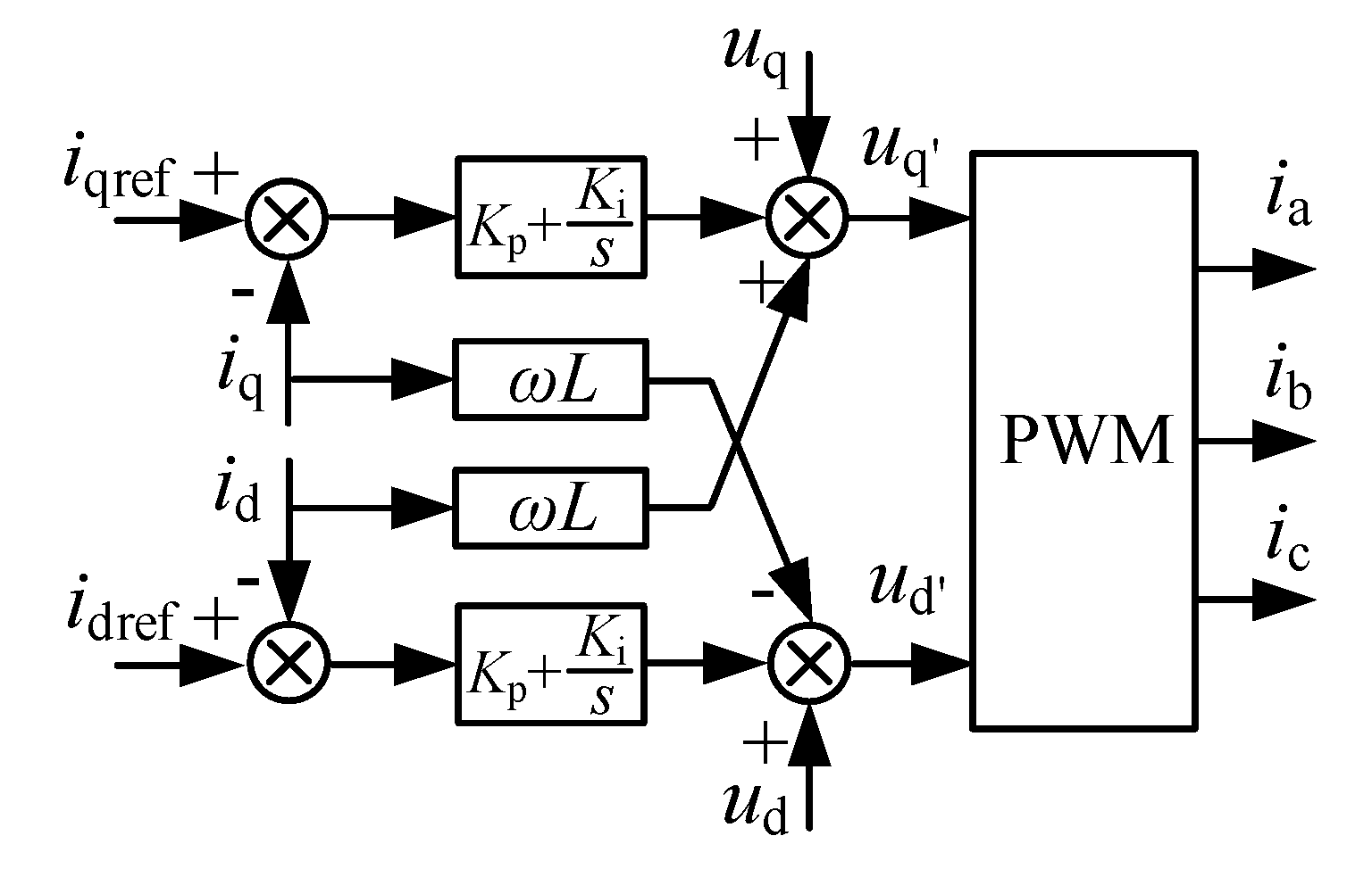
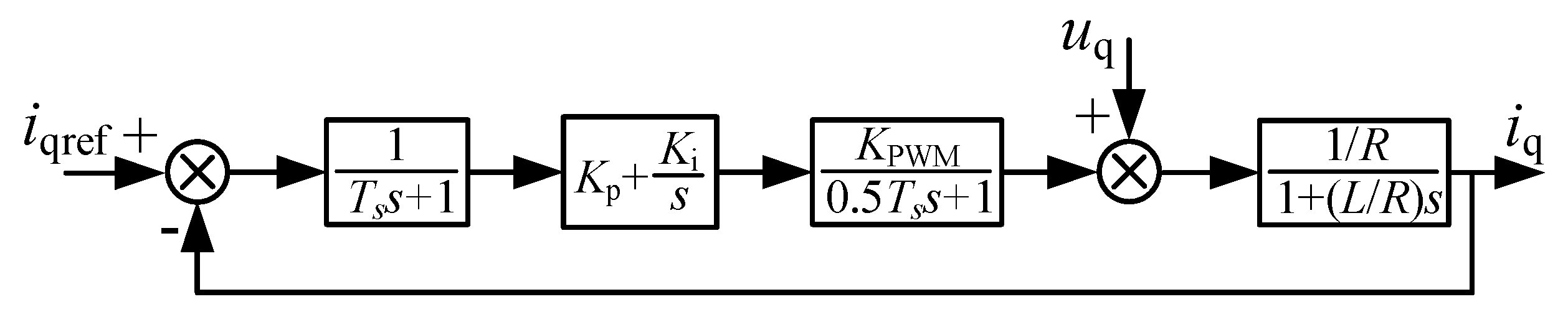
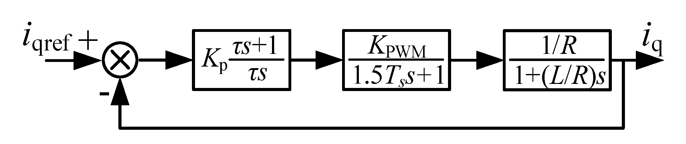
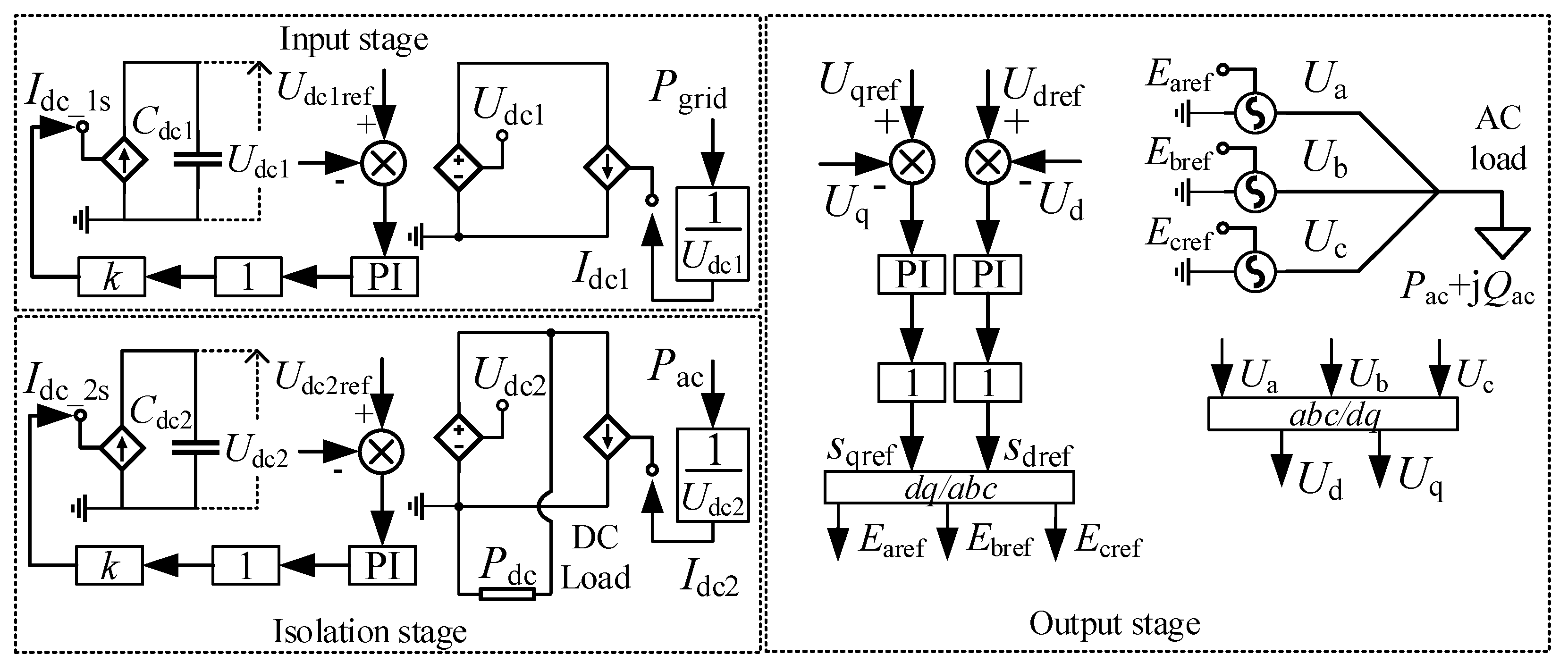
2. Methods
3. Results
3.1. Simulation Time and Accuracy Analysis
3.2. Characteristic Analysis under Fault Conditions
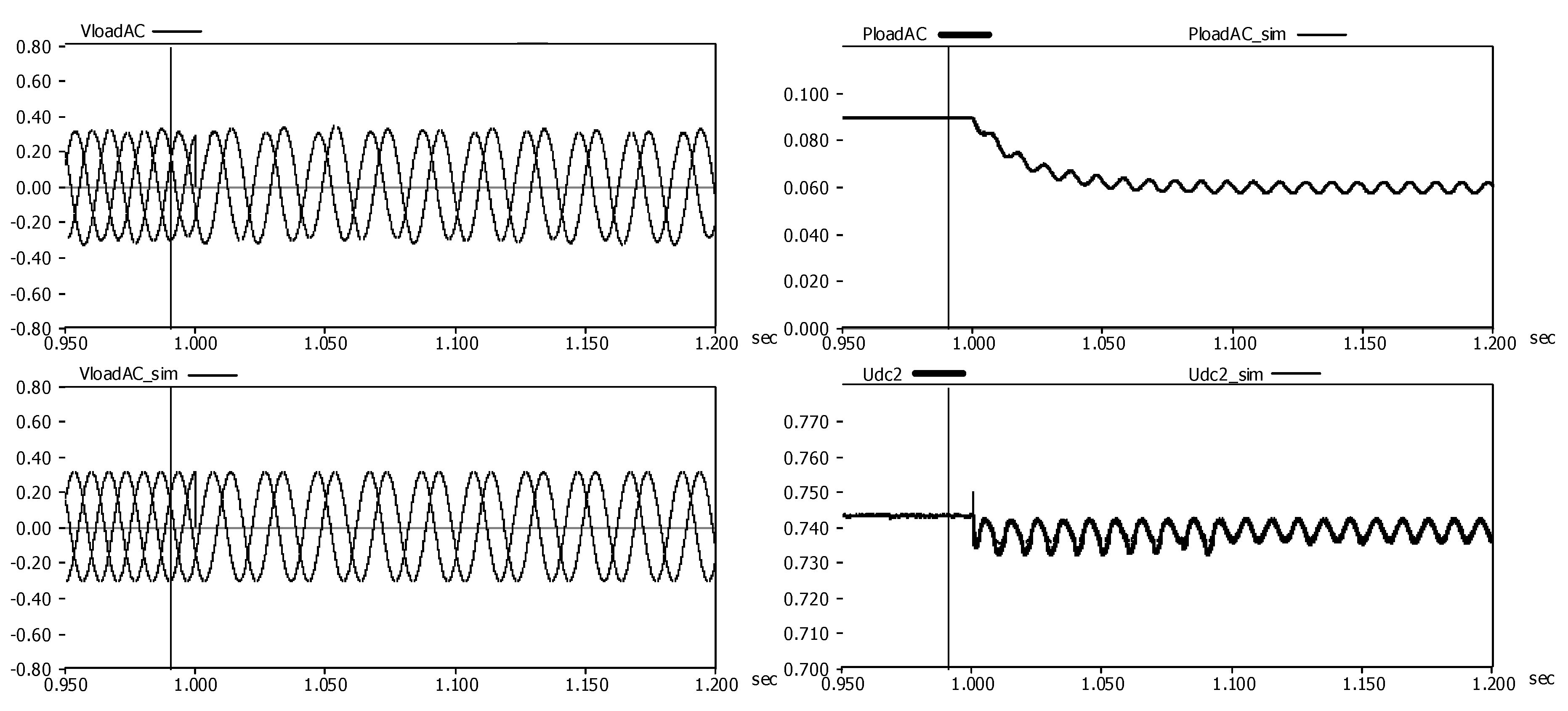
3.2.1. Characteristic Analysis under AC Load Side Fault Conditions
3.2.2. Characteristic Analysis under DC Load Side Fault Conditions
4. Conclusions
- In the AC/DC hybrid microgrid model, the microgrid network, except for the generators, was taken as the research object. This model transforms the response time scale to milliseconds, simplifies the converter and its control system, and applies controllable power sources to replace the converter.
- Through the mathematical model equivalent simplification method, there is no need to apply a new program or algorithm. The reduction of the amount of simulation data can reduce the dependence on the performance of the computer.
- The simplified model proposed in this paper improves the simulation efficiency, the output characteristics of which maintain good consistency with those of the detailed model under AC or DC load side fault conditions.
- The simplification of this paper is for each rectifier or inverter module connected by the power balance relationship. It could be applied to other more complex network topologies including more modules.
Author Contributions
Funding
Conflicts of Interest
References
- Zhao, G.; Wang, D. Comprehensive evaluation of AC/DC hybrid microgrid planning based on analytic hierarchy process and entropy weight method. Appl. Sci. 2019, 9, 3843. [Google Scholar] [CrossRef] [Green Version]
- Pan, H.; Ding, M.; Chen, A.; Bi, R.; Sun, L.; Shi, S. Research on distributed power capacity and site optimization planning of AC/DC hybrid micrograms considering line factors. Energies 2018, 11, 1930. [Google Scholar] [CrossRef] [Green Version]
- Gai, X.; Wang, Y.; Chen, R.; Zou, L. Research on hybrid microgrid based on simultaneous AC and DC distribution network and its power router. Energies 2019, 12, 1077. [Google Scholar] [CrossRef] [Green Version]
- Asghar, F.; Talha, M.; Kim, S.H. Robust frequency and voltage stability control strategy for standalone AC/DC hybrid microgrid. Energies 2017, 10, 760. [Google Scholar] [CrossRef] [Green Version]
- Baek, J.; Choi, W.; Chae, S. Distributed control strategy for autonomous operation of hybrid AC/DC microgrid. Energies 2017, 10, 373. [Google Scholar] [CrossRef] [Green Version]
- Brando, G.; Bova, B.; Cervone, A.; Dannier, A.; Del Pizzo, A. A distribution power electronic transformer with MMC. Appl. Sci. 2018, 8, 120. [Google Scholar] [CrossRef] [Green Version]
- Shi, S.M.; Wang, X.F.; Zhong, F. The research of typical control strategy of electronic power transformer in parallel operation. In Proceedings of the IEEE Advanced Information Management, Communicates, Electronic and Automation Control Conference (IMCEC), Xi’an, China, 3–5 October 2016. [Google Scholar]
- Duan, Q.; Wang, J.H.; Ma, C.Y. Flexible power distribution unit—A novel power electronic transformer development and demonstration for distribution system. In Proceedings of the IECON 41st Annual Conference of the IEEE Industrial Electronics Society, Yokohama, Japan, 9–12 November 2015. [Google Scholar]
- Zhu, M.L.; Geng, S.B.; Li, Y.G. Protected control strategies for voltage-source-converter (VSC) under grid faults in AC/DC hybrid grid. In Proceedings of the International Power Electronics and Application Conference and Exposition, Shanghai, China, 5–8 November 2014. [Google Scholar]
- Yang, J.; John, E.F.; John, O. Short-circuit and ground fault analyses and location in VSC-based DC network cables. IEEE Trans. Ind. Electron. 2012, 59, 3827–3837. [Google Scholar] [CrossRef] [Green Version]
- Dolara, A.; Ogliari, E.; Raboni, P. Ground fault analysis in a microgrid scenario. In Proceedings of the IEEE Milan PowerTech, Milan, Italy, 23–27 June 2019. [Google Scholar]
- Ramazan, B.; Erdal, I.; Fatih, I. Short-circuit fault analysis on microgrid. In Proceedings of the International Conference on Renewable Energy Research and Applications (ICRERA), Palermo, Italy, 22–25 November 2015. [Google Scholar]
- Zhao, M.; Zheng, X. Waveform characteristic analysis and recognition of short-circuit fault in grid-connected AC microgrid. In Proceedings of the 4th International Conference on Intelligent Green Building and Smart Grid (IGBSG), Yichang, China, 6–9 September 2019. [Google Scholar]
- Wang, Z.; Li, Y.; Li, Z.; Zhao, C.; Gao, F.; Wang, P. Reduced-order DC terminal dynamic model for multi-port AC-DC power electronic transformer. Energies 2019, 12, 2130. [Google Scholar] [CrossRef] [Green Version]
- Md, R.; Jacob, A.M.; Jonathan, W.K. Reduced-order small-signal model of microgrid systems. IEEE Trans. Sustain. Energy 2015, 6, 1292–1305. [Google Scholar]
- Petr, V.; Huang, P.H.; Mohamed, A.H. High-fidelity model order reduction for microgrids stability assessment. IEEE Trans. Power Syst. 2018, 33, 874–887. [Google Scholar]
- Valerio, M.; Francesco, V.; Juan, C.V. Model order reductions for stability analysis of islanded microgrids with droop control. IEEE Trans. Ind. Electron. 2015, 62, 4344–4354. [Google Scholar]
- Peng, Y.L.; Shuai, Z.K.; John, S. Reduced order modeling method of inverter-based microgrid for stability analysis. In Proceedings of the IEEE Applied Power Electronics Conference and Exposition (APEC), Tampa, FL, USA, 26–30 March 2017. [Google Scholar]
- Wang, Y.; Lu, Z.X.; Min, Y. Small signal analysis of microgrid with multiple micro sources based on reduced order model in islanding operation. In Proceedings of the IEEE Power and Energy Society General Meeting, Detroit, MI, USA, 24–28 July 2011. [Google Scholar]
- Alsseid, A.M.; Jovcic, D.; Starkey, A. Small signal modelling and stability analysis of multiterminal VSC-HVDC. In Proceedings of the 14th European Conference on Power Electronics and Applications, Birmingham, UK, 30 August–1 September 2011; pp. 1–10. [Google Scholar]
- Liu, X.J.; Guo, D. Study on equivalent simplified model of photovoltaic power generation system. Acta Energy Sol. Sin. 2016, 37, 759–764. [Google Scholar]
- Xu, K.; Wang, W.J.; Jia, L.H. Influence of AC unbalanced fault on DC side of hybrid AC/DC microgrid. Proc. CSEE. 2018, 38, 4429–4437. [Google Scholar]


| Type | Simulation Step Size/μs | Detailed Model | Simplified Model | Time-Consumption Ratio |
|---|---|---|---|---|
| Microgrid | 5 | 398 | 39 | 10.2 |
| 20 | 122 | 18 | 6.8 |
| Output Steady State Value | 0–1 s | 1–1.5 s | 1.5–2 s | |
|---|---|---|---|---|
| PloadAC /MW | Detailed model | 0.090 | 0.180 | 0.180 |
| Simplified model | 0.090 | 0.180 | 0.180 | |
| Error/% | 0.0 | 0.0 | 0.0 | |
| Udc2 /MW | Detailed model | 0.743 | 0.738 | 0.743 |
| Simplified model | 0.750 | 0.750 | 0.750 | |
| Error/% | 0.9 | 1.6 | 0.9 | |
| PloadDC /MW | Detailed model | 0.196 | 0.194 | 0.098 |
| Simplified model | 0.200 | 0.200 | 0.100 | |
| Error/% | 2.0 | 3.1 | 2.0 | |
| Pgrid /MW | Detailed model | 0.296 | 0.388 | 0.287 |
| Simplified model | 0.290 | 0.380 | 0.280 | |
| Error/% | 2.0 | 2.1 | 2.4 | |
© 2020 by the authors. Licensee MDPI, Basel, Switzerland. This article is an open access article distributed under the terms and conditions of the Creative Commons Attribution (CC BY) license (http://creativecommons.org/licenses/by/4.0/).
Share and Cite
Yao, T.; Li, Z.; Qu, J.; Li, Z.; Zhao, Q.; Zhao, G. Research on Simplified Model of AC/DC Hybrid Microgrid for Fault Analysis. Electronics 2020, 9, 358. https://doi.org/10.3390/electronics9020358
Yao T, Li Z, Qu J, Li Z, Zhao Q, Zhao G. Research on Simplified Model of AC/DC Hybrid Microgrid for Fault Analysis. Electronics. 2020; 9(2):358. https://doi.org/10.3390/electronics9020358
Chicago/Turabian StyleYao, Tianliang, Zhiwei Li, Jiping Qu, Zhaoxiong Li, Qi Zhao, and Guopeng Zhao. 2020. "Research on Simplified Model of AC/DC Hybrid Microgrid for Fault Analysis" Electronics 9, no. 2: 358. https://doi.org/10.3390/electronics9020358