1. Introduction
The Internet of Things paradigm has achieved an enormous integration level inside the technology distributed all around the world. It covers from consumer electronics, such as Wi-Fi controlled thermostats, to industrial or professional applications, such as a Wireless Sensor Network (WSN) registering data all along a whole forest. The future of communication protocols could also lead to bigger growths on new IoT system implementations, e.g., real-time systems collecting data from dozens of sensors around a fabric to optimize manufacturing operations dynamically. Therefore, the development of this kind of platforms looks promising.
The traditional hardware solutions that were used in Wireless Sensor Networks mostly relied on de-facto standard sensor motes, such as Micas and TelosB [
1], or similar approaches where 8-bit or 16-bit-based microcontrollers were integrated as the core of the wireless devices, to perform simple yet energy-efficient tasks for the target application. During the last decade tens of hardware platforms for the Extreme Edge [
2] of the IoT have appeared with different elements and focusing on aspects such as low power consumption, high processing capabilities or open HW philosophy, among others [
3]. Although these hardware platforms have been valid for many WSN application contexts, the ongoing revolution of IoT is pushing the hardware implementation towards the integration of more complex capabilities that allow tackling the challenges of smart and highly dynamic scenarios [
4], particularly concerning the arising end-to-end IoT security issues with such an amount of expected Edge devices in place. In this sense, the traditional behavior of a WSN, in which the devices remained in sleep modes for a very long period of time (thus the main consumption components to be considered were the deep power modes) and then wake up to transmit a sensing measurement to a root device, is changing to more active collaborations among participant sensors, in which the type of features they provide to the local or overall IoT Edge deployment becomes a key performance element of the system. In such scenarios, protecting the relationships among the nodes is crucial to assure data integrity and security on the Edge.
Nonetheless, it seems that practical implementation problems of IoT networks are always related to security and reliability issues. One of the many reasons is that those networks are usually built up from many nodes that have some restrictions on energy consumption and processing capabilities. Thus, they are often designed as tiny embedded systems with low-cost processors that do not have the enough computational power to implement security systems. However, if the problems associated with a lack of security capabilities are ignored, several disasters on the network and on the products related to it can indeed appeared. A common mistake on simple IoT products deployment is to think that data exchanged by the nodes on the Edge is not critical, as it does not contain private data about users, e.g., humidity sensors sensing moisture measurements to the central node that controls the overall climate of one house. However, since the security process is too simple or may not even exist on these nodes, an attacker could take control of one node and then scale privileges through upper layers of the network, reaching cloud server and the data located there.
The problem resides not only in the ability of the attacker to scale privileges in the network. Actions taken inside the nodes on the Edge might be also harmful for the system and for the users. Although many people might think that an attacker stealing data related to the temperature of their rooms is not a real threat, other systems may suffer from this uncontrolled access to the Edge. A good example of that is the research made by the authors in [
5], where they analyzed the security problems within the Philips Hue lamps. In this case, the authors were able to infer the key that protects the firmware updates of the lamps, by measuring the patterns on the power consumption of the main chip while making cryptographic tasks. Then, they could upload new custom versions of the firmware to the lamps by just requesting it to the chip, once a minimum distance from the node is reached. Upon this update being accepted, the new firmware can be programmed to request the same update to other lamps on the network, propagating itself such as an infection. The ability to change the software that controls the nodes is the key to allow the attackers to cause several problems to the users. Looking at those lamps, the authors remark the possibility of causing epileptic attacks to users by generating stroboscopic lights. In this context, some solutions are being proposed by the community [
6] in different ways, software-wise as well as hardware-wise. The security issue in IoT is certainly gaining more attention presently, and new approaches are being proposed to improve this aspect. For instance, some authors present testbeds to approach the difficult task of assessing security in IoT deployments [
7].
In this work, these main concerns related to the security on the Edge of IoT are addressed, by creating a hardware platform that combines a main processing core with a Hardware Security Module in a modular and flexible architecture, so as to foster protection strategies for current and future sensor network deployments. Different techniques are used to guarantee privacy and integrity in the data collected by sensor nodes, as well as mechanisms to join the network in a trustable manner. The design and implementation of the hardware layer have been conceived to produce a trade-off solution between computational performance, power consumption awareness and high degree of protection with dedicated hardware resources, particularly considering the increasingly importance of the active operations of the nodes in IoT dynamic contexts. The runtime self-diagnosis management of the Edge node by providing power and functional islands, real-time current consumption monitoring and an extended range of operational modes for advanced power profiles are key features that this work takes into account to provide dynamic adaptation for the target application scenarios.
Secondly, in order to validate and provide a baseline hardware and software platform for supporting distributed IoT Extreme Edge applications, a lightweight and robust multi-hop communication strategy for the Extreme Edge of IoT is proposed in this work (called Extreme-LT Routing) that allows verifying the dynamic deployment, discovery, data processing and dissemination of IoT devices in a reliable yet low-power resource-constrained fashion. The presented routing algorithm is based on the self-composition of the network topology based on the deployment conditions of the wireless nodes to find the best possible routes for the given circumstances, so as to achieve an optimized data delivery from the sensing nodes to the Edge of the IoT layers. The design and implementation of this technique is included as an embedded software component of the proposed IoT platform, and it has been used as the support communication capability to analyze its behavior and performance in real IoT Extreme Edge deployments, through the realization of intensive experimental tests, as shown in the outcomes of the work.
The main contributions of this work can be summarized as follows:
A modular hardware platform for the edge and extreme edge of the IoT, with HW enhancements for security, trustability and protection against hacking. It includes the implementation of enhanced low-power profiles to provide a trade-off solution between more demanding processing capabilities yet reduced energy consumption.
An extreme lightweight transmission protocol for multi-hop packet routing in resource-constrained IoT edge sensor networks. Its main features are simplicity, robustness, efficiency and hardware Independence.
A detailed and extensive set of real experimental tests to study the performance of the proposed solutions on the actual hardware implementation. The enhanced low-power profiles as well as the dynamics of the proposed transmission technique are deeply analyzed.
The rest of the article is organized as follows:
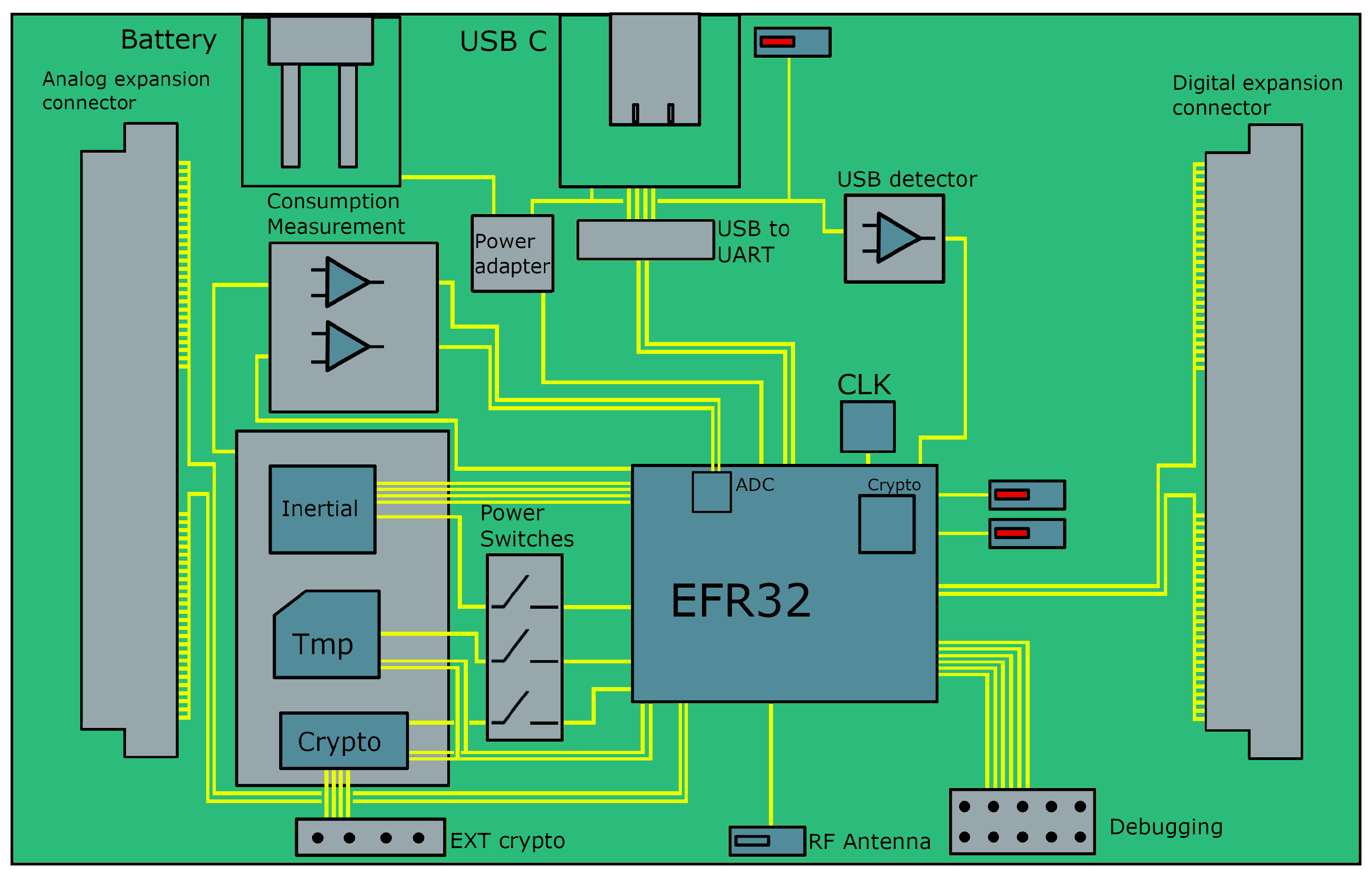
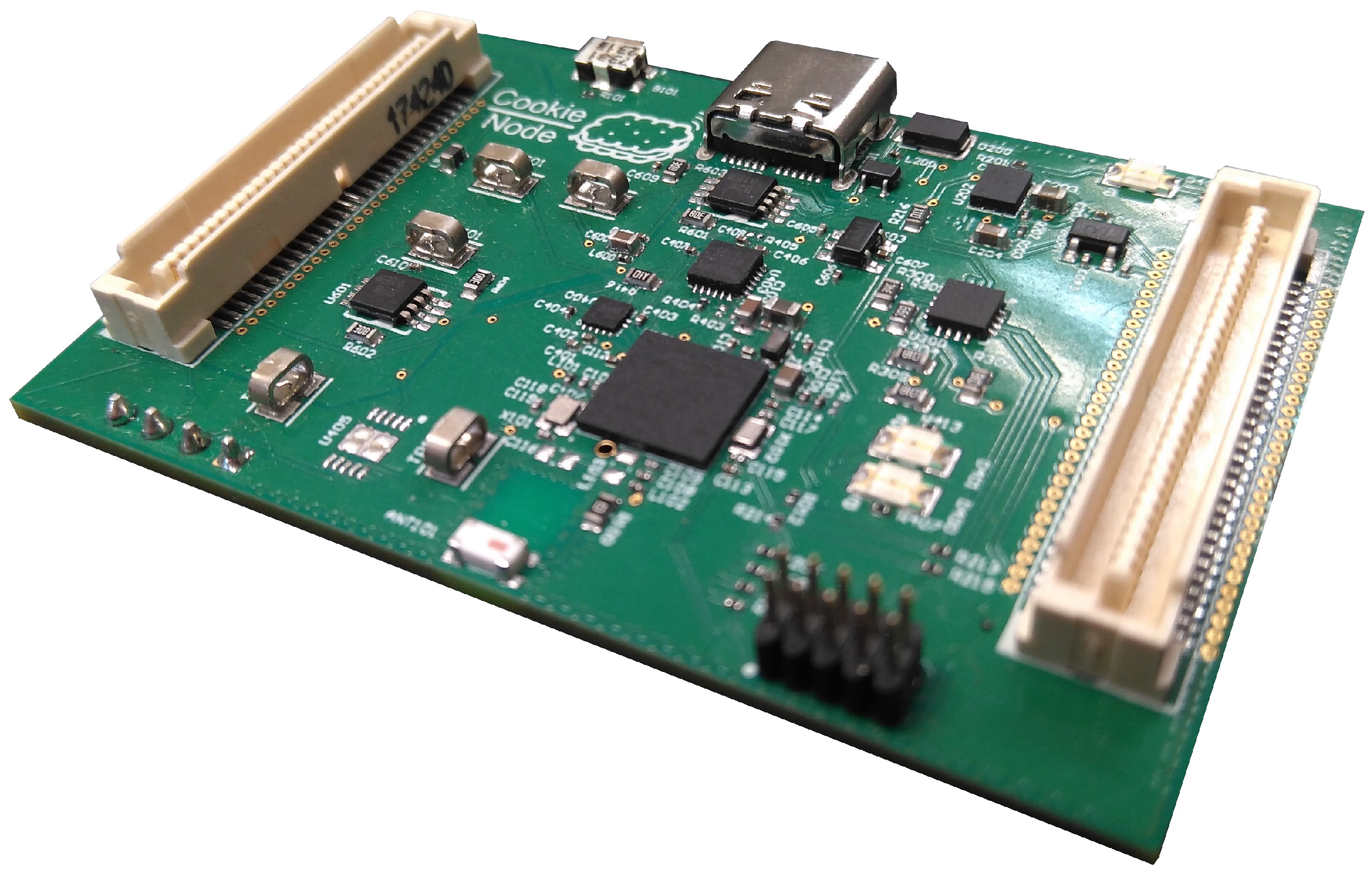
Section 2 presents the Cookie modular platform, the particular design and implementation under study in this paper and its main features, as well as the porting and integration of the Contiki-NG operating system into the proposed hardware platform.
Section 3 introduces the security aspects of the Internet of Things and their relevance on wireless sensor networks. The implementation of the security solution in the aforementioned platform is also proposed. Then,
Section 4 is devoted to detail the lightweight multi-hop communication strategy for dynamic data processing and dissemination on the Extreme Edge, which is intensively tested and validated in
Section 4.2, where the experimental results are presented and discussed. Finally, conclusions and future works are highlighted in
Section 5.
3. Security on the Extreme Edge
Protecting the Edge and particularly the Extreme Edge is one of the main pillars of the proposed modular platform, so as to provide trustability, robustness and reliability in the increasingly complex and diverse application scenarios of IoT. Traditionally, the security issue has been deeply studied in Internet, networking and computer science. However, the ubiquity of IoT devices introduces new elements to the equation, and more vulnerabilities should be considered to be protected from potential attackers. The security schemes are known to have a difficult implementation in real deployments of IoT networks. The operations that take place in common schemes may spend a large amount of time, in comparison with the usual time that a node should be active performing sensing, processing and communication tasks. This is an important issue when the approach for saving energy is to have the nodes in active mode the minimum required time, and move them to a sleep mode whenever possible. Thus, the addition of security capabilities to this type of networks must consider the extra power consumption that will appear.
Moreover, in the new IoT world, it is common to find networks composed of embedded devices that use communication protocols that do not necessarily have access to Internet, as in case of the wireless sensor networks (WSNs), which are oriented to low data rate and low-power consumption. Internet is a network that is continuously being monitored to find irregularities and attacks, but this is certainly not the case of the WSN domain.
The security on the Edge of the IoT is a very serious problem that is being addressed by the scientific community. In this regard, in [
23] a security agent is introduced, which is a hardware element with enough resources to carry out advanced security algorithms. This element offloads the security tasks from the restricted sensor nodes, which are working on measuring and sending information to the network wirelessly, although they represent a source of vulnerability, as detailed before. This is the main reason tackling the security and trustability problem directly from the Extreme Edge perspective is gaining important attention.
In this way, one of the main aspects to be considered is that the security should rely on securing the criptographic key, and the ability to keep it hidden from potential attackers, so that a trustable communication between the different parties of the network can be guaranteed. Moreover, side-channel attacks should be foreseen, especially when an attacker may have physical access to deployed nodes. This work focuses on these principles by protecting the key inside the IoT nodes, using dedicated hardware with enhanced capabilities in this regard, with very few overheads in terms of cost and power consumption.
3.1. The Chain of Trust on the Edge
When two members do not know each other, they need to establish a root of trust. This technique is based on the fact that the manufacturer of the equipment or a Certificate Authority (CA) acts as a third member that provides confidence by giving legitimacy to the relationship between the public key and the member who claims to have it.
This process (known as Public Key Infrastructure, or PKI) is a combination of different elements and procedures that allow the execution of the encryption, signature and non-repudiation of transactions or electronic communications using asymmetric cryptography, with guarantees during the whole process. Using PKI, members that do not know each other can authenticate and trust among them before starting a communication. This is done by means of using signatures and certificates. The process consists of the creation of certificates, by the CA, for each device. Subsequently, each member has the public key of the CA with which it is possible to check the validity of the member’s certificate with the one a communication (and thus an authentication process) has to be performed. The certificate is a data structure that contains relevant information about the device including its public key, and it is signed by the CA.
This concepts have been brought to the Extreme Edge by the design and implementation of the proposed new Cookie platform, combining the main processing core with a so-called Hardware Security Module (HSM). This dedicated accelerator allows providing the chain of trust with enhanced security capabilities in a transparent and efficient fashion, thus creating a protected modular and trustable hardware node for the Extreme Edge of IoT, as described in the following paragraphs.
3.2. Cookie Node with Enhanced Hardware Security
The Cookie node ensures security and trustability on the Extreme Edge by using the ATECC608A HSM designed by Microchip Inc., which is directly attached to the main I
2C bus, as stated previously in the description of the hardware modules. This chip accomplishes two main tasks. First, the power and time consumption of the cryptographic operations are moved from the software running at the microcontroller to a hardware accelerator, and second, it serves as a trustable module inside the node, meaning that it provides security to store sensitive data inside the platform that will not be discovered by side-channel attacks [
24].
The most common strategy adopted when facing the security issue in IoT systems, is the use of symmetric and asymmetric schemes in a mixed fashion, where the authentication processes of the nodes relies on the asymmetric part, and the message exchange is done with symmetric algorithms. These are known to be more efficient if the communication channel is trustable [
25]. For asymmetric authentication, usually Elliptic-Curve Cryptography (ECC) is the preferred choice, since the same security level can be achieved with smaller key sizes compared to other alternatives, such as RSA [
26]. On the symmetric scheme, the most spread cypher is the Advanced Encryption Standard (AES) with a key length of 128 bits. With this scenario in mind, the ATECC608A was chosen because it provides hardware acceleration for both NIST standard P256 ECC and AES algorithms, and also, the corresponding procedure to switch from asymmetric to symmetric schemes, which is, in this case, the Elliptic-Curve Diffie–Hellman (ECDH) algorithm.
Regarding the capabilities of the HSM to work as an isolated trustable environment, many considerations about its configuration must be done before accessing it from the microcontroller. In order to provide authentication based on a chain of trust, two certificates must be generated prior to the final deployment of the network. The first one identifies the CA, and it is stored in all the HSMs. The second one identifies the HSM itself, and it is signed by the previous CA. Both certificates are stored in a compressed X.509 format in this isolated environment, and must be validated by all the parties involved in the authentication process, prior to verifying the private key associated with the public key included inside the device’s certificate. Such a private key is also generated during the configuration stage inside the HSM, and it is never delivered outside the chip under any request. Shared keys for the AES-128 implementation are internally generated by this chip and thus they are never shown.
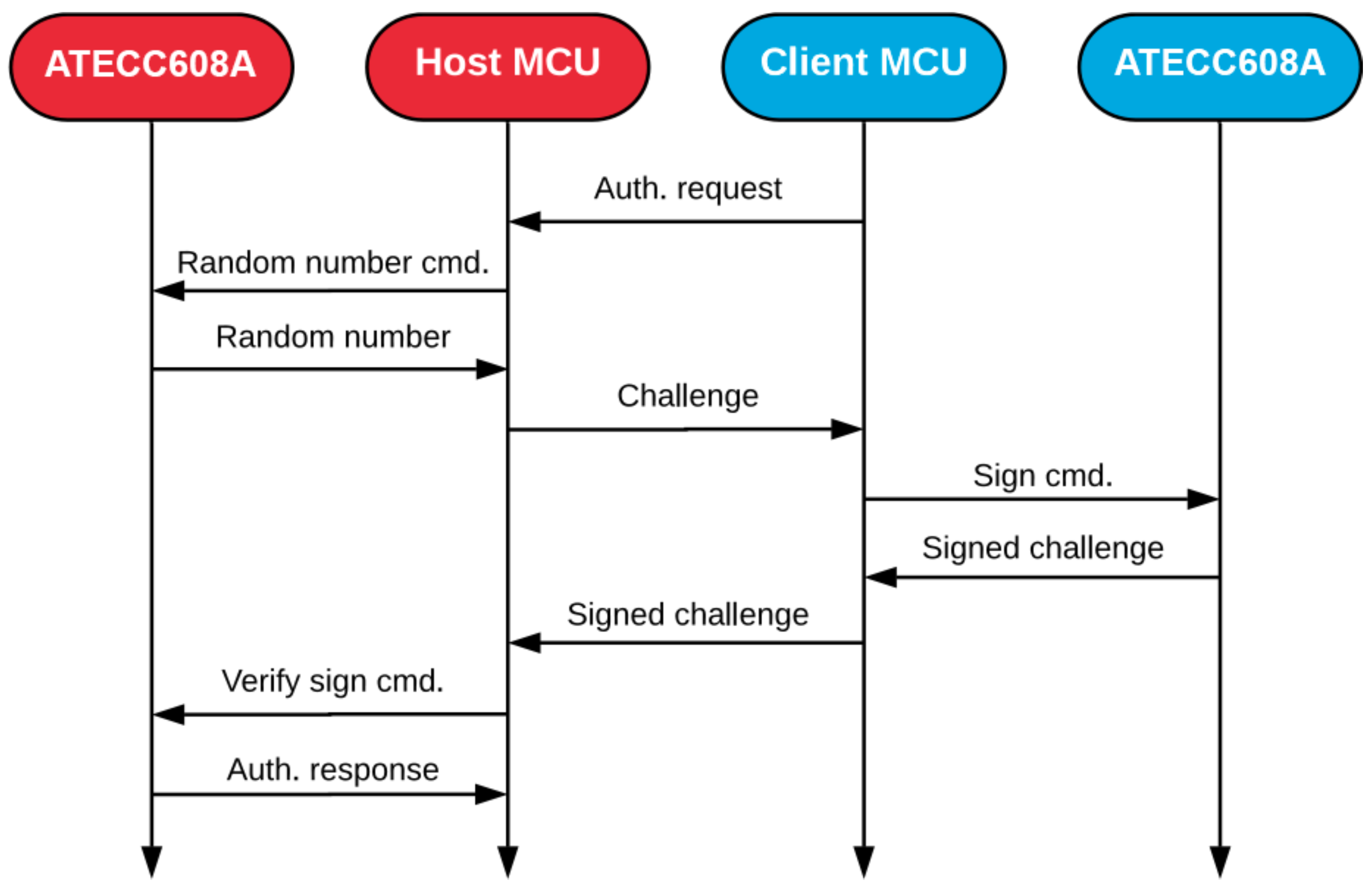
As already stated, the whole authentication process involves two stages, where the public keys are validated against the signed certificates, and the private key is later checked to be correct. In the first step, certificates are requested to the HSM by the microcontroller, and are exchanged over the network, to perform a validation of the signs and get the public ECC keys of each node. First, the CA’s certificate is checked, followed by the device’s certificate, where this public key actually resides. The second stage is to verify the private key that is supposed to be the corresponding one to the announced public key. This is done by generating a random number and request for the new node to sign it with its private key, and test the result against the already known public key. All of this is performed with the help of the hardware acceleration provided by the HSM, and the sequence of operations are described in
Figure 4.
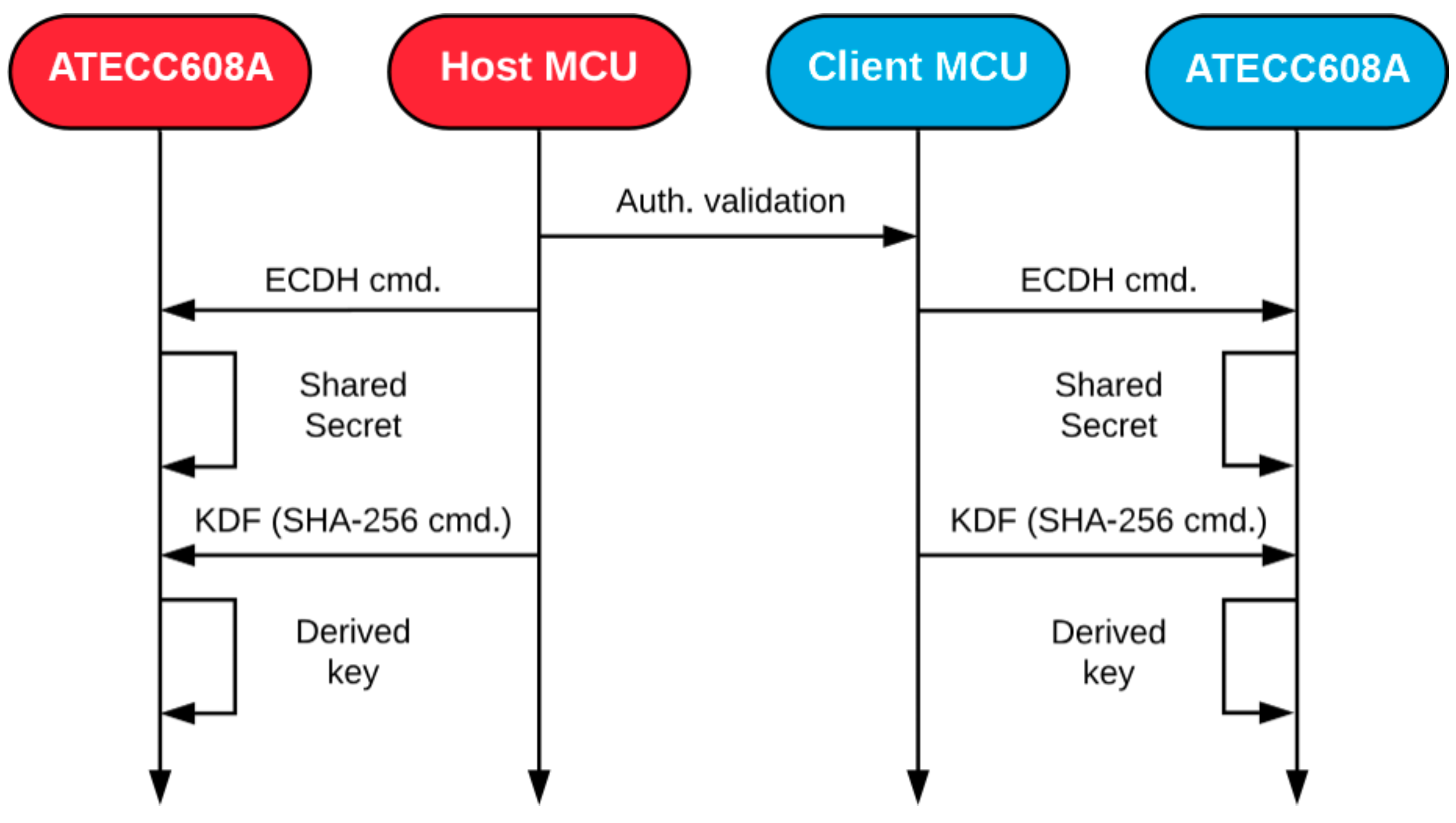
If the new node succeeds in the verification process, it is labelled as a trustable party. Thus, full communication availability should be allowed. Continuing with the previous ideas, a switch to a symmetric cyphering method is made. The sensor node benefits from the capabilities of the HSM to accelerate the ECDH key exchange that generates a shared secret between the two nodes from the asymmetric key pairs. Since the ECDH algorithm is computed on each node separately, an eventual “authentication confirmed” message should be sent to the new node to coordinate the operation. After both nodes get what is called the pre-master shared secret, a Key Derivation Function (KDF), also available in the HSM, hashes the result one more time. This extra step adds randomness to the previous ECDH operation, and makes the following digest more suitable to use as a symmetric key. A time diagram for this stage is shown in
Figure 5.
Once the secure channel for communications has been established, the rest of the messages can be cyphered with the AES-128 algorithm. Notice that the HSM does not support commonly used AES methods of operation, such as AES-CBC (Cypher-block chaining) or AES-CTR (Counter) [
27]. Instead, it only provides acceleration of a basic AES engine that works with a single block of 16 bytes. Working only with the engine is not secure because it would not spread the information between different blocks of data, and the resulting cyphertext could not be random enough compared to the original plaintext source. Therefore, it is compulsory for a good performance of the symmetric scheme to coordinate the AES engine of the HSM with an extra help from the microcontroller, to get the behavior of the already mentioned modes of operation.
The main microcontroller of the platform running the software in the sensor nodes also provides its own inner hardware accelerator for AES.
Table 4 compares the time spent between this accelerator and the HSM to perform the same encryption tasks, considering different AES modes. Notice that the external HSM provides a better time performance compared to the inner accelerator of the microcontroller, even with the need for additional support from the software part to coordinate the relationships between different blocks (128 bits each one) in the AES-CBC and AES-CTR modes. This reduction in the consumed time, in combination with the low-power characteristics of the HSM, makes this a suitable solution for securing real deployments of IoT edge networks. The added overheads and power consumption is minimum compared to the whole behavior of the network, even with the authentication processes that usually take more time to complete, since those are, in principle, only executed once, and the enhanced security justifies the approach of using a dedicated hardware.
Finally, each message exchange should be coupled with a Message Authentication Code (MAC), which allows the destination node to check if there was any error. This MAC can be generated by hashing the message with the SHA-256 function in the HSM. Another alternative would be to take advantage of the Galois field multiplication hardware accelerator of the HSM, which can be used to incorporate the AES-GCM (Galois/Counter Mode) operation [
28] to the scheme. This mode calculates and adds the needed authentication code during the cyphering process, saving computational time.
4. The Extreme-LT Routing Protocol
As a means of validating and testing the performance of the Cookie platform in multi-hop distributed deployment contexts, the design and implementation of a dynamic and adaptive routing strategy is proposed in this work, seeking reliability yet lightweight operation for the Extreme Edge. The presented routing algorithm is based on the self-composition of the network topology based on the deployment conditions of the wireless nodes in the target scenario, to find and update the best possible routes for the given circumstances in a lightweight and dynamic fashion, so as to achieve an optimized data delivery from the sensing nodes to the Edge of the IoT layers.
There are some studies in the literature exploring the diverse options for the choice of IoT routing protocols. In [
29], the authors focus on ad-hoc routing and study several protocols based on different mechanisms such as distance vector or link state. Another IoT routing protocol is RPL (Routing Protocol for Low-Power and Lossy Networks, [
30]), which is widely used and supported by many IoT platforms and operating systems. This is reflected in the existence of many adaptations and variations for it, to enhance its performance in certain scenarios ([
31,
32,
33]), as well as reviews of RPL-based protocols such as the one in [
34].
The Extreme Edge Lightweight Transmission protocol (Extreme-LT) is a lightweight routing protocol developed at the Center of Industrial Electronics (CEI-UPM) for its use on the Cookie modular platform. It is a distance vector routing protocol for IoT networks, focused on simplicity, robustness and reduced processing load. It pursues the goals of reliability, robustness, efficiency and hardware independence set by CTP (Collection Tree Protocol, [
35]), adapting and simplifying some mechanisms used by other protocols.
The protocol distinguishes between two node types: sending nodes and a root node. A network will always be composed of a root node, acting as a sink, and a variable number of sending nodes, establishing a tree topology. In this sense, Extreme-LT builds a Destination Oriented Directed Acyclic Graph (DODAG, [
30]), similar to the ones used in other IoT routing protocols such as RPL.
The protocol is designed as a simple solution to route messages from the sending nodes to the sink, and since it is conceived to tackle the scenarios where the majority of traffic is directed to the sink node, and having in mind that the environment is lossy and routes are expected to change frequently, there is no necessity to store the whole upstream route in the node using routing tables, as seen in other protocols. Instead, each node only needs to know the route to its parent. Because of this, the choice of the best parent among the candidates is of utmost importance to the establishment of the tree and the optimization of the network topology. For the construction of the DODAG, the protocol uses the rank information and Received Signal Strength Indication (RSSI) as the metric to determine the best parent node from all the potential ones. The procedure to assign the rank of a node follows the following expression:
With a rank increase per hop of 1 by default, the node rank is equal to the hop count from the root, resulting in the same metric that RPL implements for its Objective Function Zero (OF0, [
36]). According to Yassien et al. [
37], OF0 is not inferior to MRHOF (Minimum Rank with Hysteresis Objective Function, [
38]) in terms of Packet Delivery Ratio (PDR) and power consumption, and even outperforms it in some scenarios. On top of that, Extreme-LT imposes a tie-break policy for equal rank candidates based on their RSSI.
Since a node has no routes stored other than the one pointing to its parent node, for downstream communications the protocol either uses unicast transmissions when it is a response to an upstream message, or uses broadcast messages for the nodes to filter in reception. The former is the usual solution, while the latter is restricted to specific situations to avoid flooding the medium.
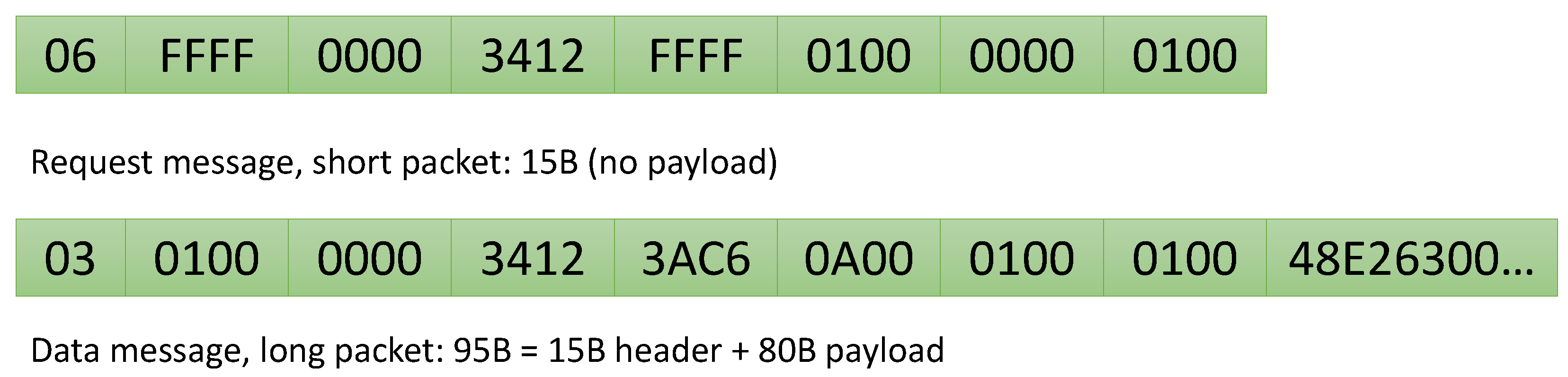
For any given packet being transmitted, the network protocol header frame format includes data from the sender node, such as the node ID, its rank within the network topology or the DAG ID, as well as information related to the packet itself, such as the packet type or the packet number to keep track of the total number of packets sent from a sending node. Different DODAGs, with different DAG IDs, can coexist at the same time.
The protocol relies on the usage of several packet types, ranging from data packets to various kinds of control packets: Request, Discovery (network advertisement), Repair Unicast and Repair Broadcast. These packets have a common header, specific to the protocol, and an optional payload. In particular, data packets have a payload and control packets do not have it. The header frame format of the protocol is shown in
Figure 6. To illustrate this frame format, different packet frames can be seen in the examples shown in
Figure 7.
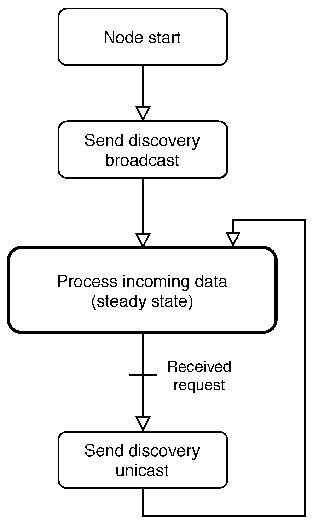
The general functionality of a sending node under the protocol can be seen as a state machine in
Figure 8, and
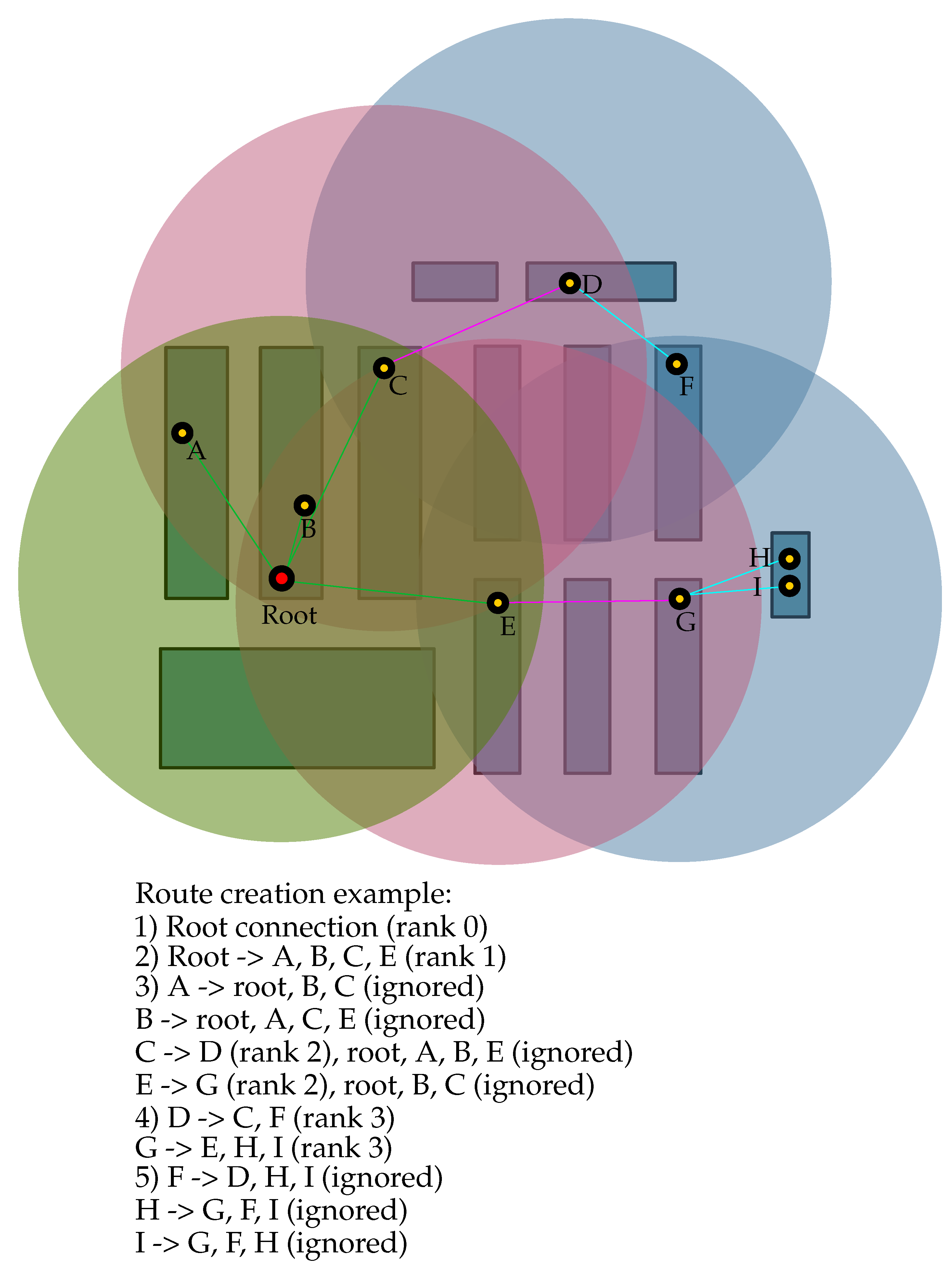
Figure 9 shows the corresponding one for the root node. The purpose of the sending nodes is to connect to the network in the best possible conditions, to then start measuring data from the sensors and sending it towards the sink node. For this, a sending node will broadcast a request message when booted. This is the first route creation mechanism provided by the protocol. Any node that receives this message will respond with a unicast discovery message directed to that node. The discovery message contains network advertisement information, including the rank of the node within the network topology. The new node will retrieve the network information from the message and store the node ID as its parent, assigning itself a rank one step higher than the rank of the parent. When other nodes in range also receive the request and send their discovery messages back to the new node, if their rank is better than the current parent or they have equal rank but a higher RSSI, the new node will accept them as its new parent node, replacing the former one. If the rank is lower, the discovery message will be ignored. This mechanism ensures that every node will connect to the reachable parent that offers the best connection to the sink, optimizing the route composition and reducing the number of relay hops as much as possible.
The same request-discovery mechanism triggers when a node loses connection to its parent. When a node encounters a fatal transmission problem at its data link layer, after retrying for a given amount of attempts, the node will delete its parent and broadcast a request, accepting a new parent with the best rank from the nodes within its range. After that, it will broadcast a repair command so that their child nodes can repair themselves, updating their routes and ranks. From the perspective of the rest of the network, this mechanism works as if the node had just been turned on as a new addition to the network, although internally the node will increase its sequence number, so it can track the number of times it has been forced to repair its route.
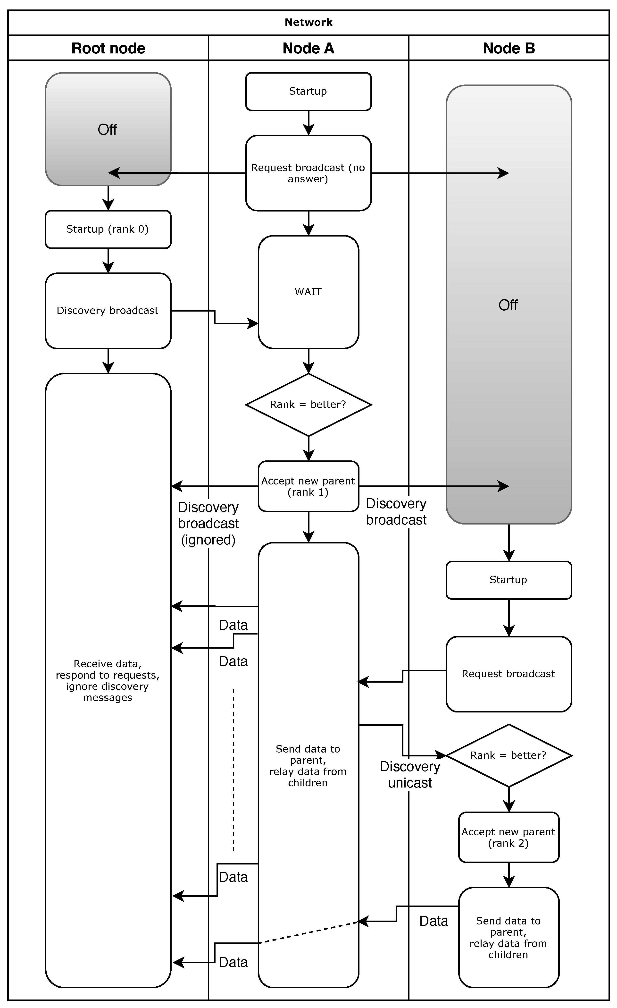
The second mechanism apart from the request-discovery method, is the network creation from the root. When the root node is booted, it will broadcast a discovery message to advertise the network. Every node in range will connect directly to it, since the sink has rank 0, and spread the network advertisement by broadcasting a discovery message with their own rank. Both mechanisms coexist so the creation of the network can be done in a flexible way, while also making it robust in case of new additions or changes in the topology. An example of a normal startup, depicting both mechanisms, is shown in
Figure 10. The flow chart shows a situation where a node A is deployed on its own, with no other nodes nearby to connect to. It will request a rank and receive no answer. After that, the root node is plugged. It will create a network and broadcast a discovery message that node A will receive, accepting the root as its parent node. It will then spread the discovery to other nodes (none in this case). After a while, a node B is connected, and will broadcast a request as node A did. Assuming that the root node is out of range and node A is the only one able to respond to, it will send back a discovery message, being a unicast in this case. Node B will accept node A as its new parent and then it can begin the data transmission towards the network sink through it.
After the network is established, the nodes will start sending their data to the sink node. For this, the data packets are always sent to the parent node. The node will first inspect the packet header, checking if the destination is their own node ID or another node ID upstream, i.e., the root ID. It will also check if the rank of the sending node is correct. If it is correct, it will relay the message upstream, or process the content of the payload if the destination was its own node ID. If not, there is an error in the network, since that node should not be sending data to this one. The node will ignore the data packet and send back a unicast repair message.
When a node receives a repair command, it will first filter it compared to its parent node ID. A node will only accept repair commands from its parent. If the sender node ID is the node ID stored as parent, the node will delete it and broadcast a request. After this, it will send broadcast a repair command so its child nodes, if any, will repair themselves and update their routes and ranks. The protocol can be condensed into these two rules:
A node will only send data packets to its parent node. A data packet from a lower ranked node implies the network topology has changed and needs to be repaired.
A node will only accept repair commands from its parent node. Repair commands received from any other node will be ignored.
The robustness of the protocol comes from its simplicity. Loops are avoided by ensuring a node will only accept a parent if its rank is the best among all reachable nodes, and will only accept repair commands from the node it has stored as its parent. Discovery messages from nodes with a rank that is not better than the current one will be ignored, and repair commands received from any node that is not its parent will be ignored as well.
As a summary, Extreme-LT is a distance vector protocol developed for the testing and validation of the Cookie platform, but not exclusive to it. It is based on the creation of DODAGs, relying on the robustness granted by the route creation mechanism to implement a reactive maintenance strategy. This way the control packet flow within the network is minimized, reducing the route overheads.
The following section presents the tests carried out on the hardware platform to validate its performance under the protocol, detailing the testing conditions and procedure, the parameters used and the results obtained, which are analyzed and discussed subsequently.
4.1. Preliminary Tests
4.1.1. Range Tests
Before testing the performance of the nodes using the protocol, outdoor tests have been carried out to determine the transmission power of the Cookie platform and the maximum acceptable range of communication. The setup for the tests consisted on a sender node, deployed in a fixed position at ground level, sending packets periodically to a receiver node. The transmission power was set at 20 dBm, which is the maximum power gain of the antenna. The distance between the nodes was initially 1.5 m from which the receiver node was moved away, increasing the separation until the sink node was eventually unable to receive messages. This end condition was met at an approximate distance of over 130 m, beyond that distance the RSSI of the incoming messages was −85 dBm or lower and some of the packets were lost.
4.1.2. Traffic Tests
The next set of tests were designed to create heavy traffic conditions on the sink node and evaluate its capability to receive and process data from several nodes under such conditions. For this, the setup consisted on a receiver node connected to a terminal and 10 sending nodes deployed around it. Transmission power was set at −15 dBm. After being connected, all sender nodes started sending messages to the sink with the following parameters: sending interval = 0.1 s; packet size per transmission = 95 B; minimum number of iterations per node = 1000 (which means that the test lasted until every sending node had sent at least 1000 packets). This sets a worst-case scenario to analyze the performance of the protocol under such conditions. The results obtained are shown in
Table 5, computing a total amount of 11041 packets, with PDR (number of packets received at the destination divided by the packets sent by the source, expressed as a percentage) mean equal to 98,4 %. From these outcomes, where the worst PDR was more than 96%, it can be concluded that the sink node is able to endure heavy traffic conditions, being able to receive and process most of the messages sent to it (certainly very close to 100%).
The results of these preliminary tests ensure the sink node will be able to support the incoming traffic and also determine the maximum transmission range of the nodes, and serve as the baseline for the following rounds of testing, in which the performance of the nodes under the routing protocol will be tested.
4.2. Extreme-LT Experimental Evaluation and Results
4.2.1. Setup, Test Procedure and End Conditions
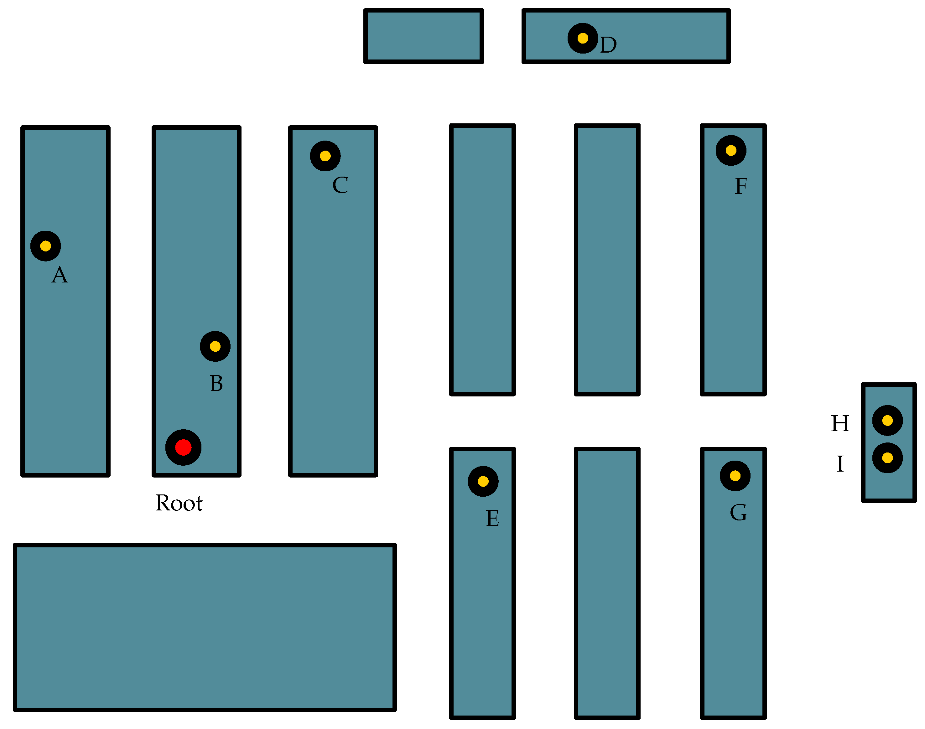
Once the functionality of the platform was verified, a series of tests were performed to trial its behavior under the protocol dynamics, particularly pushing its operation to very extreme boundaries. For these tests, the nodes were deployed in an indoor environment, with the network distribution shown in
Figure 11. In this schematic representation of the main lab room (approximately 238 m
), the red dot represents the root node, acting as a sink, and the yellow dots represent the sensor nodes, able to both generate messages on their own and relay messages from other nodes. The rectangles represent the working disposition of the lab, just as a reference to show the distribution of the nodes and the different locations used during the deployment and testing process.
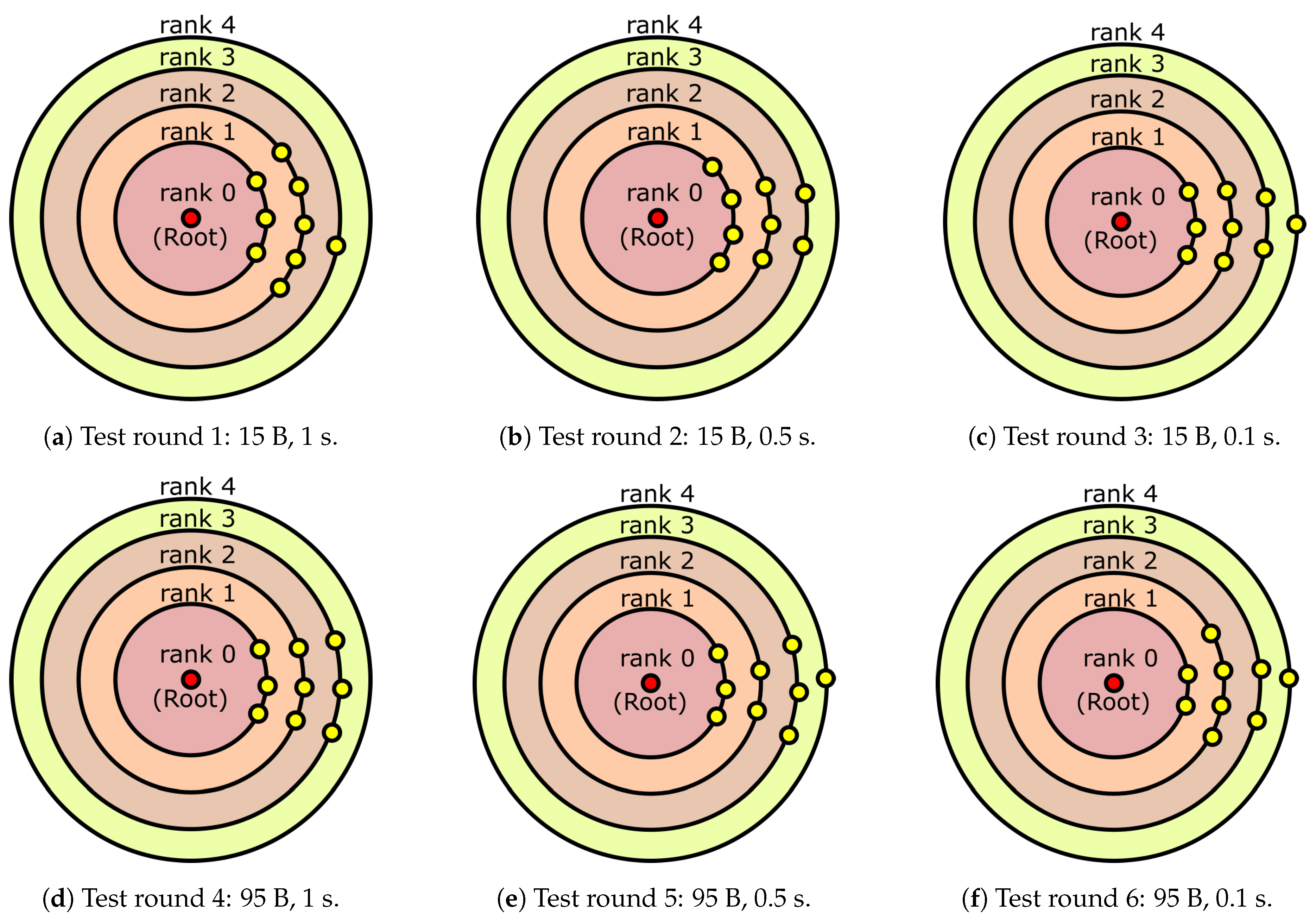
The setup parameters considered to perform the experimental tests are configured as follows: two packet sizes were used: small packets, with a length equal to 15 B, and large packets, with a length equal to 95 B. These two sizes correspond to those of control and data packets used by the protocol. The message interval for the sender nodes was established at 1 s, 0.5 s and 0.1 s respectively (so very aggressive traffic conditions, in which all the nodes are transmitting and routing packets intensively), with 3 different intervals tested over 2 different packet sizes, for a total of 6 test rounds, where each node generates a minimum of 1000 packets per iteration, as shown below. This setup parameters are summarized in
Table 6.
For each round of testing, the sensor nodes were deployed and turned on in the positions shown in
Figure 11, then the root node was connected. By connecting the root node last, the route creation will start from the root node and propagate downstream to the rest of the nodes. This is the second network creation mechanism described in the protocol. An example of the network creation procedure for the setup used in the tests is shown in
Figure 12. The topology is established by the network depending on the deployment conditions of the moment. After joining the network, each sensor node started sending packets towards the root node, be it directly or through multiple hops, bouncing in the intermediate sensor nodes. The distribution of the nodes in the lab was the same for all the tests, with their positions fixed, and the connections between them were established automatically according to the protocol, thereby creating some differences in the position of each individual node within the topology.
Because of these differences, the nodes will not be addressed individually but attending to their rank in the network: the sink node has rank 0, the nodes directly sending to it have rank 1, and so on.
Each round of testing was stopped after every node had sent a minimum of 1000 packets to the sink. With this, the PDR of the nodes can be measured and compared, to determine the impact of the packet size and sending interval.
4.2.2. Test results and discussion
The results obtained for each node, sorted by node rank, can be seen in
Table 7. For each of the rounds of testing, the route creation mechanism established the network topology, resulting in the node distribution shown in
Figure 13a–f.
From these results, it can be concluded that as expected, a lower sending interval increases the time the nodes are busy, making a node less capable of relaying messages. This condition makes the routing protocol produce more disperse routes with less child nodes per parent over a highly ramified tree, with many nodes connected to a single node in the same branch. This is, when the saturation of the nodes increases, the protocol tends to form N-ary subtrees with a lower N. In this way, the protocol avoids bottlenecks at route creation, even if it implies that the network will have a higher traffic overall (which ultimately compensates for the possibility of losing packets and/or the number of retransmissions produced by bottlenecks).
In these circumstances, a node that could have rank 2 connecting directly to a rank-1 parent node has instead rank 3, because the rank 1 parent node is saturated and does not accept the request from a potential child node (which then connects to a higher rank node that is less saturated). On the other hand, this decision will effectively increase the traffic of the network, since the intermediate rank 1 node will have to route messages coming from all the nodes of its branch, regardless of whether they are sent directly to it or through a relay node.
Also, the congestion comes with a higher packet loss rate. By lowering the sending interval, the PDR from the higher rank nodes drops, reaching rates around 70% in the worst cases. This is due to the higher load put on the relay nodes, since those nodes must send their own messages and redirect messages coming from their child nodes.
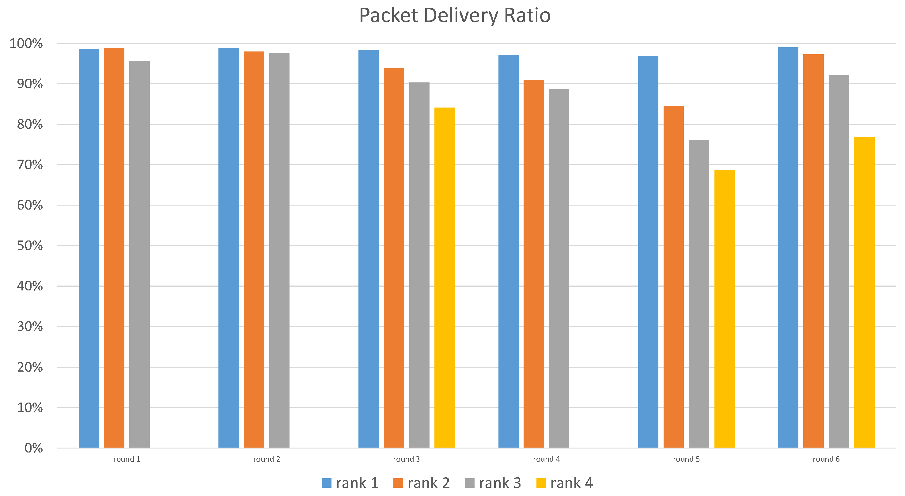
For an easier interpretation, the results of each round of tests have been merged, grouping the received and total number of messages attending to the rank of the nodes and obtaining a combined PDR of the nodes with rank 1, rank 2 and so on. These combined results are depicted in
Table 8.
A comparison of these results is presented in
Figure 14. There is indeed a tendency to avoid bottleneck nodes and disseminate the routes. Such a tendency is accentuated as the sending interval decreases, as can be seen when comparing the results from round 3 to rounds 1 or 2, but there is no direct correlation between the increase in sending frequency and a lower PDR in some cases. As the figure shows for rounds 5 and 6, a faster sending interval (T = 0.1 s) for the same packet size forced the network to route packets in a different way, achieving better delivery rates for each rank than those obtained for a slower message frequency (T = 0.5 s). This is explained by the route creation mechanism. The protocol chooses the best available parent at route creation, selecting the node with the best rank and RSSI as a new parent. Once the route is created and all nodes have started sending, it may occur that the parent node is saturated most of the time due to the high message load from other nodes, being unable to route messages. Thus, the node will delete it and look for a new one, selecting a parent able to correctly receive and route its messages (event with a higher rank) due to having lower load. In a less saturated scenario, the node might retain its initial parent and stay working under heavier traffic conditions, resulting in a lower PDR. In more saturated circumstances, this initial parent was rejected due to its high load and incapability to relay all the messages it received, resulting in a better PDR due to the reactive mechanism that establishes the routes.
Another aspect that stands out is the relationship between packet size and PDR. It is expected that bigger packet sizes will put a heavier load on the nodes and cause an increment in the time the nodes are busy processing the data, thus reducing the idle time they have left to relay messages from downstream nodes. A decrease in PDR is therefore expected, more noticeable as the number of hops increases. As it can be seen when comparing results obtained from rounds 1 and 4, or rounds 2 and 5, a bigger packet size for the same sending interval results in a worse PDR for nodes of the same rank. Also, it is important to highlight that the created traffic is a very extreme case of a normal application context, so it allowed to analyze experimentally the performance of the multi-hop communication strategy and the designed Cookie node under adverse traffic conditions.
5. Conclusions and Future Work
In this work the new version of the Cookie node for the Extreme Edge of IoT is fully presented, a modular hardware platform conceived and designed to provide trustability and robustness necessary for the present and future of IoT applications, and based on the flexibility and scalability paradigm of the Cookie platform. The functionality of this Edge node has been showcased in real experimental performance tests to validate both the hardware and software integration of the proposed system. Additionally, a porting of the Contiki-NG operating system to the platform has been developed as an example of the flexibility and adaptability that is targeted with this new IoT sensor node, which opens the possibility of porting different operating systems into the platform in the future.
Moreover, a lightweight routing protocol designed for sink networks, one of the most commonly used topologies in IoT, is also presented. The protocol takes advantage of mechanisms used by other protocols and implements a simple, lightweight and robust multi-hop communication strategy for the Extreme Edge of IoT. Its performance has been tested on the Cookie platform, obtaining an extensive analysis of the routing mechanism within intensive communication scenarios with heavy traffic patterns, where the amount of data to be transmitted within the network has been overloaded to study the behavior of the sensor nodes within such extreme conditions.
On the other hand, security is a major concern in IoT, and the Edge is the most vulnerable part of the whole ecosystem. A hardware platform with a security-conscious conception during the design and implementation of the proposed Cookie Edge Node solution has been introduced. With very few costs and power consumption overheads, the security increases dramatically. Overall, the results show that a high balance between performance, security and power awareness, and self-diagnosis in dynamic scenarios (where the active operation, participation and collaboration among the nodes is an increasingly common feature in IoT), is certainly possible with the proposed design in this work. In this sense, the proposed Cookie platform is currently being used in practical use cases within the railway field, to provide trustability and chain of trust for on-board and on-track sensor network deployments. The presented platform is serving as the baseline IoT sensor node technology for such application contexts, and further in-field network deployments will be fully supported by this hardware platform.


