Article

Novel Summation-Type Triggering Condition on Event-Based Memory Output Feedback Control for Networked Control Systems

1
Electronics and Telecommunications Research Institute (ETRI), Smart Mobility Research Section, Daegu 42994, Korea
2
Agency for Defense Development (ADD), The 1st R&D Institute-5th Directorate, Daejeon 34186, Korea
*
Author to whom correspondence should be addressed.
Electronics 2020, 9(5), 779; https://doi.org/10.3390/electronics9050779
Submission received: 5 April 2020 / Revised: 3 May 2020 / Accepted: 4 May 2020 / Published: 8 May 2020
(This article belongs to the Section Systems & Control Engineering)

Abstract

:
Networked control systems are widely spread, which is composed of numerous sensor and control nodes through communication channel. In this paper, an event-triggered H memory output feedback control (EMOFC) is investigated for networked control linear systems in discrete form. The memory control employing memorized past information is exploited to enhance the triggering intervals under event-triggered condition. Moreover, novel summation type event-triggering condition is newly proposed by utilizing buffer memory element. Based upon memory control and novel triggering conditions, the control design methodology is constructed for transformed input-delay model in forms of linear matrix inequalities (LMIs) adopting generalized free-weighting matrix summation inequality. As a result, the proposed scheme shows off the reduction of average signal transmission frequency and reliability while covering standard condition. Throughout numerical examples, the effectiveness is shown and the effect of memory element is analyzed.

1. Introduction

Networked control system (NCS) is a control system where the closed control loop includes communication network [1,2]. The developments in wired and wireless communication networks have given rise to the NCS due to its advantages in cost, installation, and maintenance. Thus, a number of researchers have paid much attention to the NCS [3,4,5]. However, the design of control in NCS confronts several difficulties since networked channels are comparably unreliable, unlike the traditional way of point to point direct connection. In network communication, network transmission delay [6], packet disorder [7], and packet loss [8] are unavoidable as well as network resources are limited. In these limited network sources, it is waste to send all measurement signals. Hence, it is of great importance not only for academic theory but for practicality to improve the efficiency of the network while maintaining the performance of the system.
Event-triggered control (ETC) scheme [9], which can be utilized in limited bandwidth network, has been proposed in order to save the network resources. Event-trigger mechanism implies that only some signals satisfying the predefined triggering condition are transmitted to the controller node, so there is no need to transmit all measurement signals. Therefore, ETC scheme much reduces inefficient utilization of limited network resources by using only some redundant measurement signals. Since the first approach on event-triggering control for linear systems, it has been widely applied to various systems including nonlinear systems [10], multi-agent systems [11], Markov jump systems [12], and complex dynamical networks [13]. As well as, it is worth noting that the aforementioned ETSs performed in the continuous-time linear NCSs framework has widely extended to discrete-time systems [14,15]. As is known, network-based communications are inherent of discrete nature since packet-based protocols are regularly used to connect the components of the NCSs not composed of a continuous flow of information in a classic way. Thus, it is more natural and effective way to handle NCS in discrete form.
In the implementation of ETC [16], there have been two main issues: the first one is the design of proper triggering condition. The other one is to deal with physical constraints of network communication such as network-induced delay [17], input/state quantization [18,19], and packet drop [20]. The first one is a study on the several causes for the instability of network control systems, the second is about to save the resources of the network. Since the complexity increases as the number of sensor/controllers connected to the network increases, the event triggering condition to save the resources of the network is becoming more of importance. In accordance with the fact, a bunch of studies are investigated on triggering conditions while covering network constraints. As follows, the absolute ETC scheme has been investigated for discrete-time systems, ensuring input to state stability [21]. The trigger using absolute event-triggering condition is active when the measured state is over than a certain value but it is lack of flexibility. Thus, the relative event-triggering mechanism is widely studied with various type of controllers: state feedback [22], output feedback [23], and observer-based control [24]. Remarkably, it is found that relative triggering performance is degraded when the system state approached to the equilibrium point. The mixed approach was conducted to obtain superior performance [25]. As an alternative, integral type triggering condition [26] has been proposed for improved triggering intervals, so occupied network resources have been saved. However, the integral type is unnatural and may cause excessive triggering under disturbances.
Recently, memory event-triggering scheme [27] has been studied to address these properties. Owing to previously generated information, this approach provides the additional flexibility for application to real system. However, the existing research is limited drawbacks that it is noteworthy that presented study on memory triggering condition only considers recently sampled signals with state-dependent time-varying threshold parameter. There is still room for improvement for the triggering condition. The triggering condition has a major impact on the reduction of average signal transmission frequency. In another aspects, memory state feedback control requires all information of the system state to implement under event-triggered mechanism in the continuous form. Unfortunately, such requirement is difficult and even impossible to be satisfied in practical cases based on the discrete form. Thus, output feedback control is mandatory to apply in most practical applications. As such, practical memory ETC scheme must require a more natural and effective way. Our research is motivated by the above discussions.
In this paper, event-triggered memory output feedback control (EMOFC) for discrete-time NCS with the network-induced delay is investigated. Employing additional buffer element in the network loop, memory control is implemented, which contributes to improve reliability and compensate system performances. In addition, novel summation type triggering condition is proposed to save network resources using memorized information. Therefore, it helps to reduce the usage of average signals in the network. The proposed approach provides a more general event-triggering framework, which can contain existing relative triggering condition. The design criterion with proposed memory control and novel summation type triggering condition is derived by utilizing Finsler’s Lemma and summation type inequalities, which is advantageous on filling nonnegative diagonal matrix. The constructed results are presented with guaranteeing stability and H performance in forms of linear matrix inequalities. Finally, simulation results illustrate the effectiveness of the proposed method.

2. Problem Statement and Preliminaries

Let us consider the following linear systems in discrete form.
x ( k + 1 ) = A x ( k ) + B u ( k ) + D 1 d ( k ) , y ( k ) = C x ( k ) , z ( k ) = C z x ( k ) + F u ( k ) + D 2 d ( k ) ,
where x ( k ) R n is the state of the system; u ( k ) R m is the control input signal of the system; y ( k ) R p is the output signal of the system; z ( k ) R q is the estimated output of the system; k is the time instance. A, B, C , C z , D 1 , D 2 , and F are known system matrices with appropriate dimensions.
The output feedback controller is presented as
u ( k ) = K y ( k ) ,
where K is the output feedback control gain matrix to be determined. In network description, a sensor measurement is time-triggered with a constant sampling period h, while the measurement transmission is event-triggered. The widespread event-triggering condition is as follows:
[ y ( k ) y ( k e ) ] T Ω [ y ( k ) y ( k e ) ] ρ y T ( k ) Ω y ( k ) ,
where y ( k e ) is the latest triggered output signal, Ω is a positive definite weighting matrix, and ρ is a positive scalar parameter. Taking into consideration the event-triggering scheme, the updated time of data is described as follows
k e + 1 = k e + min k { k | e T ( k ) Ω e T ( k ) ρ y T ( k ) Ω y ( k ) } ,
where k e and k e + 1 are the latest triggered instant and next triggered instant, respectively. Considering network transmission delay, the holding interval of the zero-order hold (ZOH) at controller Φ = k [ k e + τ k e , k e + 1 + τ k e + 1 1 ) can be represented as Φ = U Φ l where Φ l = [ k e + l + τ k e + l , k e + l + 1 + τ k e + l + 1 ] , l = 0 , 1 , , k e + 1 k e 1 . τ k e and τ k e + 1 are the network-induced transmission delay of the latest and next ZOH arrival data. Defining τ ( k ) = k k e l , l Ω l , then, τ ( k ) is bounded as 0 < τ ( k ) τ m + 1 = τ M , where τ m is the upper bound of the transmission delay τ k e , respectively. Then, the control gain can be rewritten as
u ( k ) = K y ( k τ ( k ) ) K e ( k ) , k Ω l
where e ( k ) = y ( k ) y ( k e ) .

3. The Memory Control and Novel Summation-Type Event-Triggered Condition

For the given system, the following serialized N 1 memory control using previously memorized output signals is proposed in this paper.
u ( k ) = K 1 y ( k e ) + K 2 y ( k e 1 ) + + K N y ( k e N + 1 ) = i = 1 N K i C x ( k e i + 1 ) i = 1 N K i e ( k i + 1 ) , k [ k e + τ k e , k e + 1 + τ k e + 1 ) ,
where k e is the latest triggered instant, N 1 is the number of memorized signal, e ( k ) = y ( k ) y ( k e ) , and K 1 , , K N are the feedback gain matrices. The whole description of NCS is detailed in Figure 1.
We propose a novel event-triggering condition to take into account the information of previous states. Utilizing memorized output signals, the summation types of event-triggering scheme are investigated.
[ y ( k ) y ( k e ) ] T Ω 1 [ y ( k ) y ( k e ) ] + [ y ( k 1 ) y ( k e 1 ) ] T Ω 1 [ y ( k 1 ) y ( k e 1 ) ] + + [ y ( k N + 1 ) y ( k e N + 1 ) ] T Ω N [ y ( k N + 1 ) y ( k e ) ] ρ 1 y T ( k ) Ω 1 y ( k ) + ρ 2 y T ( k 1 ) Ω 2 y ( k 1 ) + + ρ N y T ( k N + 1 ) Ω N y ( k N + 1 ) ,
where 0 ρ i 1 , Ω i for i = 1 , 2 , , N are the scaling parameters and weighting matrices.
Remark 1.
The proposed novel summation-type are composed of the previous output signals. It should be noted that the devised one is inherited with distributed triggering parameters and distributed weighting matrices. As a result, it provides more flexibility of the design and thus relaxes sufficient conditions. The distributed triggering parameters widen the design flexibility, and further it has an effect on the relaxation of condition by presenting additional selective matrices.
With the aid of the mentioned advantage in Remark 1, it could be applied to several networked systems including distributed coupled large-scale systems, mobile sensor networks, aircraft systems, and automated industrial factories. It is more effective in wireless networks that have limited bandwidth.
Remark 2.
Utilizing the memorized signals, the summation-type event triggering possibly send less transmission signals in connected network. Especially, the summation terms in the left side make it more difficult to violate triggering condition, which means that it result in less average signal transmission frequency on network bandwidth.
Then, the transmission update time, k e + 1 , which is determined by the event-triggering condition, is presented as follows:
k e + 1 = k e + inf k k E ( k e ) T Σ E ( k e ) Y ( k ) T Σ 1 Y ( k ) } ,
where Σ = d i a g { Ω 1 , Ω 2 , , Ω N } , and Σ 1 = d i a g { ρ 1 Ω 1 , ρ 2 Ω 2 , , ρ N Ω N } . Employing the memory output feedback control considering transmission delay, the actual control input is represented as follows:
u ( k ) = i = 1 N K i C x ( k τ ( k ) i + 1 ) i = 1 N K i e ( k i + 1 ) , k [ k e + τ k e , k e + 1 + τ k e + 1 ) .
Under the the given memory control, the whole networked control system can be rewritten as
x ( k + 1 ) = A x ( k ) + B K C X ( k τ ( k ) ) B K E ( k ) + D 1 d ( k ) , z ( k ) = C z x ( k ) + F K C X ( k τ ( k ) ) F K E ( k ) + D 2 d ( k ) , for k [ k e + τ k e , k e + 1 + τ k e + 1 ) ,
where
K = [ K 1 , K 2 , , K N ] , X ( k τ ( k ) ) = [ x ( k τ ( k ) ) , x ( k τ ( k ) 1 ) , , x ( k τ ( k ) N + 1 ) ] T , E ( k ) = [ e ( k ) , e ( k 1 ) , , e ( k N + 1 ) ] T .
The following are important lemmas that will be used in § Main Result.
Lemma 1.
(Generalized free-weighting matrix based summation inequality; [28,29]) For a positive definite symmetric matrix R R n × n , and any matrices U, V, W, L, and M with appropriate dimensions satisfying
U V L V T W M L T M T R 0 ,
then, the following summation inequality holds for vector s [ a , b ] R n , g 1 , g 2 , χ 1 , and χ 2 :
i = a b 1 s T ( j ) R s ( j ) s y m { χ 0 T L χ 1 + χ 0 T M χ 2 } + ( b a ) χ 0 T ( U + 1 3 W ) χ 0 ,
where χ 0 can be an any vector, and
χ 1 T = x ( b ) x ( a ) , χ 2 T = x ( b ) + x ( a ) 2 i = a b 1 1 b a x ( i ) .
With the fact that 3 · l 1 l + 1 3 l , Lemma 1 can be easily confirmed.
Lemma 2.
(Finsler’s Lemma; [30]) For given matrices P , B , S , and a vector w, the following conditions are equivalent:
( i ) w T P w < 0 , for all w 0 , H w = 0 ; ( i i ) B T P B < 0 ; ( i i i ) S R n × m s u c h t h a t P + S y m ( S B ) < 0 ;
such that B B = 0 .

4. Main Results

This section provides sufficient conditions of event-based H stability and H EMOFC design for linear discrete-time systems. The co-design methodology for EMOFC and the trigger parameters is given to a memory event-triggered control. The following notations are defined to simply denote the necessary variables according to the N 1 number of memory.
e i = 0 , , 0 , I , 0 , , 0 6 N + 3 Variables R n × ( 5 N n + N p + n + q + r ) for 1 i 5 N + 1 , e j = 0 , , 0 , I , 0 , , 0 6 N + 3 Variables R p × ( 5 N n + N p + n + q + r ) for 5 N + 2 i 6 N + 3 ,
e 6 N + 2 = 0 , , 0 , 0 , 0 , , I , 0 6 N + 3 Variables R q × ( 5 N n + N p + n + q + r ) , e 6 N + 3 = 0 , , 0 , 0 , 0 , , 0 , I 6 N + 3 Variables R r × ( 5 N n + N p + n + q + r ) ,
where only ith or jth block column is filled with identity matrix, otherwise zero matrix with proper dimensions.
ζ 1 T ( k ) = [ x T ( k + 1 ) , η 1 ( k ) , η 2 ( k ) , , η N ( k ) 5 N Variable , e T ( k ) , e T ( k 1 ) , e T ( k 2 ) , , e T ( k N + 1 ) N Variable , z T ( k ) , d T ( k ) ] , ζ 2 T ( k ) = [ x T ( k ) , x T ( k 1 ) , x T ( k 2 ) , , x T ( k N + 1 ) , e T ( k ) , e T ( k 1 ) , e T ( k 2 ) , , , e T ( k N + 1 ) ] , η ( k ) = [ x ( k ) , x ( k 1 ) , x ( k 2 ) , x ( k N + 1 ) ) ] , η 1 ( k ) = [ x ( k ) , x ( k τ ( k ) ) , x ( k τ M ) , i = k τ ( k ) k τ M x ( i ) τ ( k ) + 1 , i = k τ M k τ ( k ) x ( i ) τ M τ ( k ) + 1 ] , η l ( k ) = [ x ( k l + 1 ) , x ( k τ ( k ) l + 1 ) , x ( k τ M l + 1 ) , i = k τ ( k ) l + 1 k τ M l + 1 x ( i ) τ ( k ) + 1 , i = k τ M l + 1 k τ ( k ) l + 1 x ( i ) τ M τ ( k ) + 1 ] , for l = 1 , 2 , , N , E 0 = [ I , I , I , I , I ] , E 1 = [ I , I , 0 , 0 , 0 ] , E 2 = [ I , I , 2 I , 0 , 0 ] , E 3 = [ 0 , I , I , 0 , 0 ] , E 4 = [ 0 , I , I , 2 I , 0 ] .
Theorem 1.
(Stability) For given scalars N , τ M , ρ i for i = 1 , 2 , , N , and γ, if there exist positive symmetric matrices P = P 11 P 12 P 1 N P 22 P 2 N P N N R N n × N n , Q 1 R n × n , Q 2 R n × n , R i R n × n , for i = 1 , 2 , , N , and any matrices G , H , U i , a , U i , b , V i , a , V i , b , W i , a , W i , b , L i , a , L i , b , M i , a , M i , b for i = 1 , 2 , , N , and diagonal matrices Ω i for i = 1 , 2 , , N satisfying the following LMIs:
Γ = Γ 1 ( τ ( k ) ) Γ 2 Γ 3 Γ 4 Γ 5 Γ 6 0 I D 2 0 D 2 T γ 2 I < 0 ,
U i , a V i , a L i , a W i , a M i , a R i 0 , U i , b V i , b L i , b W i , b M i , b R i 0 , for l = 1 , 2 , , N , τ ( k ) [ 0 , τ M ]
where
Γ 1 = ζ 1 T ( k ) i = 1 6 Γ ^ i ζ 1 ( k ) , Γ ^ 1 = e 1 e 2 e 3 e 4 e 5 e 6 T τ M R 1 τ M R 1 0 0 0 0 Q 1 + Q 2 + τ M R 1 0 0 0 0 Q 2 0 0 0 Q 1 0 0 0 0 0 0 e 1 e 2 e 3 e 4 e 5 e 6 , Γ ^ 2 = e 1 e 2 e 7 e 5 N 8 T P e 1 e 2 e 7 e 5 N 8 , Γ ^ 3 = e 2 e 7 e 12 e 5 N 3 T P e 1 e 2 e 7 e 5 N 3 + τ M i = 2 N ( e 5 i 3 e 5 i + 2 ) R i ( e 5 i 3 e 5 i + 2 ) + i = 1 N e 5 i 2 T ρ i Ω i e 5 i 2 , Γ ^ 4 = i = 1 N e 5 i 3 e 5 i 2 e 5 i 1 e 5 i e 5 i + 1 T ( τ ( k ) E 0 ( U i , a + 1 3 W i , a ) E 0 + ( τ M τ ( k ) ) E 0 ( U i , b + 1 3 W i , b ) E 0 + s y m { E 0 L i , a E 1 + E 0 M i , a E 2 + E 0 L i , b E 3 + E 0 M i , b E 4 } ) e 5 i 3 e 5 i 2 e 5 i 1 e 5 i e 5 i + 1 , Γ ^ 5 = S y m e 1 T ( G ) e 1 + e 1 T G A e 2 + e 2 T ( H T ) e 1 + e 2 T ( H A ) e 2 + e 6 N + 2 T C z e 2 , Γ ^ 6 = S y m i = 1 N ( e 1 T G B K i C e 5 i 2 ) + S y m i = 1 N ( e 2 T H B K i C e 5 i 2 ) ,
Γ 2 = G B K 1 G B K 2 G B K 3 G B K N H B K 1 H B K 2 H B K 3 H B K N 0 0 0 0 + i = 1 N e 5 i 2 T ρ i Ω i e i + 5 N + 1 , Γ 3 = e 2 T C z T e 6 N + 2 + i = 1 N ( e 6 N + 2 T F K i C e 5 i 2 e i + 5 N + 1 ) , Γ 4 = [ G D 1 , H D 1 0 , , 0 , 0 , 0 6 N 0 ] T , Γ 5 = ( ρ 1 1 ) Ω 1 0 0 0 0 0 ( ρ 2 1 ) Ω 2 0 0 0 0 0 ( ρ 3 1 ) Ω 3 0 0 0 0 0 ( ρ 4 1 ) Ω 4 0 0 0 0 0 0 ( ρ N 1 ) Ω N , Γ 6 = i = 1 N ( e 6 N + 2 T F K i e i + 5 N + 1 ) ,
then, the closed loop system in Equation (10) is asymptotically stable under proposed event triggered condition in Equation (8) with the H performance index γ.
Proof of Theorem 1.
Consider the following LK functional candidate
V ( k ) η T ( k ) P η ( k ) + l = k τ M k 1 x T ( l ) Q 1 ( l ) + l = k τ ( k ) k 1 x T ( l ) Q 2 ( l ) + i = 1 N p = τ M + N 1 0 l k + p 1 [ x ( l + 1 ) x ( l ) ] T R i [ x ( l + 1 ) x ( l ) ] .
The discrepancy of the V ( k ) in Equation (15) from k to k + 1 is computed as
Δ V ( k ) = η T ( k + 1 ) P η ( k + 1 ) η T ( k ) P η ( k ) + x T ( k ) Q 1 x ( k ) x T ( k τ M ) Q 1 x ( k τ M ) + x T ( k ) Q 2 x ( k ) x T ( k τ ( k ) ) Q 2 x ( k τ ( k ) ) + τ M i = 1 N δ T ( k N + 1 ) R i δ ( k N + 1 ) i = 1 N s = k τ M + N 1 k + N 2 δ T ( s ) R i δ ( s ) ,
where δ ( s ) = x ( s ) x ( s 1 ) . Applying Lemma 1 on the Δ V ( k ) summation terms leads to
s = k τ M k 1 δ T ( s ) R 1 δ ( s ) η 1 T ( t ) ( τ ( k ) E 0 ( U 1 , a + 1 3 W 1 , a ) E 0 + ( τ M τ ( k ) ) E 0 ( U 1 , b + 1 3 W 1 , b ) E 0 + s y m { E 0 L 1 , a E 1 + E 0 M 1 , a E 2 + E 0 L 1 , b E 3 + E 0 M 1 , b E 4 } ) η 1 ( t ) ,
Similarly, the upper bound of i = 1 N s = k τ M + N 1 k + N 2 δ T ( s ) R i δ ( s ) can be obtained with Equation (14). Then, the upper bound of the Δ V ( k ) in Equation (15) can be arranged as
Δ V ( k ) η T ( k + 1 ) P η ( k + 1 ) η T ( k ) P η ( k ) + x T ( k ) Q 1 x ( k ) x T ( k τ M ) Q 1 x ( k τ M ) + x T ( k ) Q 2 x ( k ) x T ( k τ ( k ) ) Q 2 x ( k τ ( k ) ) + i = 1 N η i T ( k ) ( τ ( k ) E 0 ( U i , a + 1 3 W i , a ) E 0 + ( τ M τ ( k ) ) E 0 ( U i , b + 1 3 W i , b ) E 0 + s y m { E 0 L i , a E 1 + E 0 M i , a E 2 + E 0 L i , b E 3 + E 0 M i , b E 4 } ) η i + i = 1 N e ( k i + 1 ) T Ω i e ( k i + 1 ) i = 1 N e ( k i + 1 ) T Ω i e ( k i + 1 ) .
Considering the proposed summation-type event-triggering condition in Equation (8) to the bound of the Δ V ( k ) in Equation (16), the following H performance index is taken into consideration.
J = k = 0 Δ V ( k ) + z T ( k ) z ( k ) γ 2 d T ( k ) d ( k ) .
The upper bound of the J in Equation (17) can be redefined with the combined conditions as
J k = 0 ζ T ( k ) Λ T Ψ Λ ζ ( k ) < 0 ,
where
Ψ = Ψ 1 + Ψ 2 + Ψ 3 + Ψ 4 , Ψ 1 = η ( k + 1 ) T P η ( k + 1 ) η ( k ) T P η ( k ) , Ψ 2 = τ M R 1 τ M R 1 0 0 0 Q 1 + Q 2 + τ M R 1 0 0 0 ρ 1 C T Ω 1 C Q 2 0 ρ 1 C T Ω 1 Q 1 0 ( ρ 1 1 ) Ω 1 , Ψ 3 = i = 1 N η i T ( k ) ( τ ( k ) E 0 ( U i , a + 1 3 W i , a ) E 0 + ( τ M τ ( k ) ) E 0 ( U i , b + 1 3 W i , b ) E 0 + s y m { E 0 L i , a E 1 + E 0 M i , a E 2 + E 0 L i , b E 3 + E 0 M i , b E 4 } ) η i Ψ 4 = i = 2 N y ( k τ ( k ) i + 1 ) + e ( k i + 1 ) T Ω i y ( k τ ( k ) i + 1 ) + e ( k i + 1 ) i = 2 N e ( k N + 1 ) T Ω i e ( k i + 1 ) + z T ( k ) z ( k ) γ 2 d T ( k ) d ( k ) ,
ζ T ( k ) = [ η 1 ( k ) , η 2 ( k ) , , η N ( k ) 5 N Variable , e T ( k ) , e T ( k 1 ) , e T ( k 2 ) , , e T ( k N ) N Variable , d T ( k ) ] , ζ 1 T ( k ) = [ x T ( k + 1 ) , η 1 ( k ) , η 2 ( k ) , , η N ( k ) 5 N Variable , e T ( k ) , e T ( k 1 ) , e T ( k 2 ) , , e T ( k N ) N Variable , z T ( k ) , d T ( k ) ] , Λ T = A I 0 0 0 0 0 0 C 0 B K 1 C 0 I 0 0 0 0 0 F K 1 C 0 0 0 0 I 0 0 0 0 0 0 B K 1 0 0 0 0 0 0 0 F K 1 0 B K 2 0 0 0 0 0 0 0 F K 2 0 B K N 0 0 0 0 0 0 0 F K N 0 D 1 0 0 0 0 0 0 0 D 2 I .
Applying Lemma 2 in consideration of the system description in Equation (8), one can have
Ψ + S y m ( T Λ ) < 0
where
T = G T H T 0 0 0 0 5 N n n + N p 0 0 0 0 0 0 0 0 5 N n n + N p I 0 T , Λ = I , A , B K 1 C , 0 , 0 , 0 5 Variables 0 , B K 2 C , 0 , 0 , 0 5 Variables 0 , B K N C , 0 , 0 , 0 5 Variables B K 1 , B K 2 , , B K N N p 0 D 1 0 , C , F K 1 C , 0 , 0 , 0 5 Variables 0 , F K 2 C , 0 , 0 , 0 5 Variables 0 , F K N C , 0 , 0 , 0 5 Variables F K 1 , F K 2 , , F K N N p I D 2 .
Finally, one can have Equation (19), which is equivalent to the condition in Equation (13) in Theorem 1. For the signal holding time τ ( t ) , the above inequality implies that V ˙ ( t ) 0 . This complete the proof. □
Remark 3.
The proposed output feedback control and event-triggering condition are more general than existing results. If N = 1 is chosen, it can be regarded as the design of event-triggered output feedback control. If N = 1 and K 1 = K , C = I , then, the conditions are exactly equivalent to that of state-feedback control with the standard relative event-triggering condition. Therefore, the proposed condition includes the method of existing ones.
From Theorem 1, the stability for given EMOFC considering robustness to outer disturbances H can be proved. It verifies the feasibility of the given control gain. When C = I is chosen, it is easily applicable to the case of state feedback. Based on the presented Theorem 1, the problem of stabilization is handled by Lemma 2. The design method for EMOFC is presented in the Theorem 2.
Remark 4.
The utilization of generalized free-weighting matrix based summation inequality brings out not only the relaxation of the stability condition but also provides additional free matrices that can be used for filling matrices by selecting appropriate free variables.
Theorem 2.
[Stabilization] For given scalars N , τ M , ρ i for i = 1 , 2 , , N , and γ ¯ = γ 2 , if there exist positive symmetric matrices P = P 11 P 12 P 1 N P 22 P 2 N P N N R N n × N n , Q 1 R n × n , Q 2 R n × n , R i R n × n , for i = 1 , 2 , , N , and any matrices G , H , Z , U i , a , U i , b , V i , a , V i , b , W i , a , W i , b , L i , a , L i , b , M i , a , M i , b , Y i for i = 1 , 2 , , N , and diagonal matrices Ω i for i = 1 , 2 , , N satisfying the following LMIs:
Θ = Γ ˜ 1 ( τ ( k ) ) Γ ˜ 2 Γ ˜ 3 Γ 4 Θ 1 Γ 5 Γ ˜ 6 0 Θ 2 I D 2 F b 3 F Y 0 D 2 T γ ¯ I 0 ( F b 3 F Y ) T 0 b 4 Y b 4 Y T < 0 ,
U i , a V i , a L i , a W i , a M i , a R i 0 , U i , b V i , b L i , b W i , b M i , b R i 0 , for l = 1 , 2 , , N , τ ( k ) [ 0 , τ M ]
where
Γ ˜ 1 ( τ ( k ) ) = Γ 1 ( τ ( k ) ) Γ ^ 6 + S y m i = 1 N ( e 1 T b 1 B Z i C e 5 i 2 + S y m i = 1 N ( e 2 T B Z i C e i + 5 N + 1 ) , Γ ˜ 2 = i = 1 N ( e 1 T b 1 B Z i e 5 i 2 + e 2 T b 2 B Z i e i + 5 N + 1 ) , Γ ˜ 3 = e 2 T C z T e 6 N + 2 + i = 1 N ( e 6 N + 2 T b 3 F Z i C e 5 i 2 ) , Γ ˜ 6 = i = 1 N ( e 6 N + 2 T b 3 F Z i e i + 5 N + 1 ) , Θ 1 = [ ( G B b 1 B Y ) T , ( H B b 2 B Y ) T , b 4 Z 1 C , 0 , 0 , 0 5 n , 0 , b 4 Z 2 C , 0 , 0 , 0 5 n , 0 , b 4 Z N C , 0 , 0 , 0 5 n ] T , Θ 2 = [ ( b 4 Z 1 ) , ( b 4 Z 2 ) , , ( b 4 Z N ) ] T ,
then, the system is asymptotically stable with guaranteed H performance γ ( γ ¯ = γ 2 ). Moreover, the control gain is given by K i = Y 1 Z i .
Proof of Theorem 2.
From the proof of Theorem 1, Lemma 2 is reutilized with additional parameters b 1 , b 2 , b 3 , and b 4 to separate G , H from K i in Equation (18).
Γ + S y m ( S Λ 2 ) < 0 ,
where
S = [ ( b 1 B Y G B ) T , ( b 2 B Y H B ) T , 0 , , 0 , ( b 3 F Y F ) T 0 , ( b 4 Y ) T ] T , Λ 2 = [ 0 , 0 , K 1 C 0 , 0 , 0 , 5 n 0 , K 2 C 0 , 0 , 0 , 5 n , , , 5 ( N 3 ) n , 0 , K N C 0 , 0 , 0 , 5 n K 1 , K 2 , , K N N p , 0 , 0 , I ] R n × ( 5 N n + N p + n + q + r + m ) .
Then, Equation (22) is identical to Equation (24). This completes the proof. □

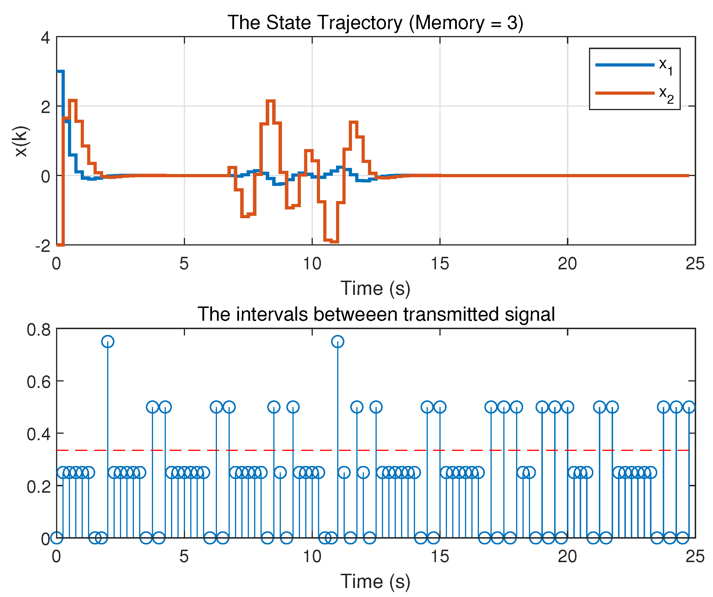
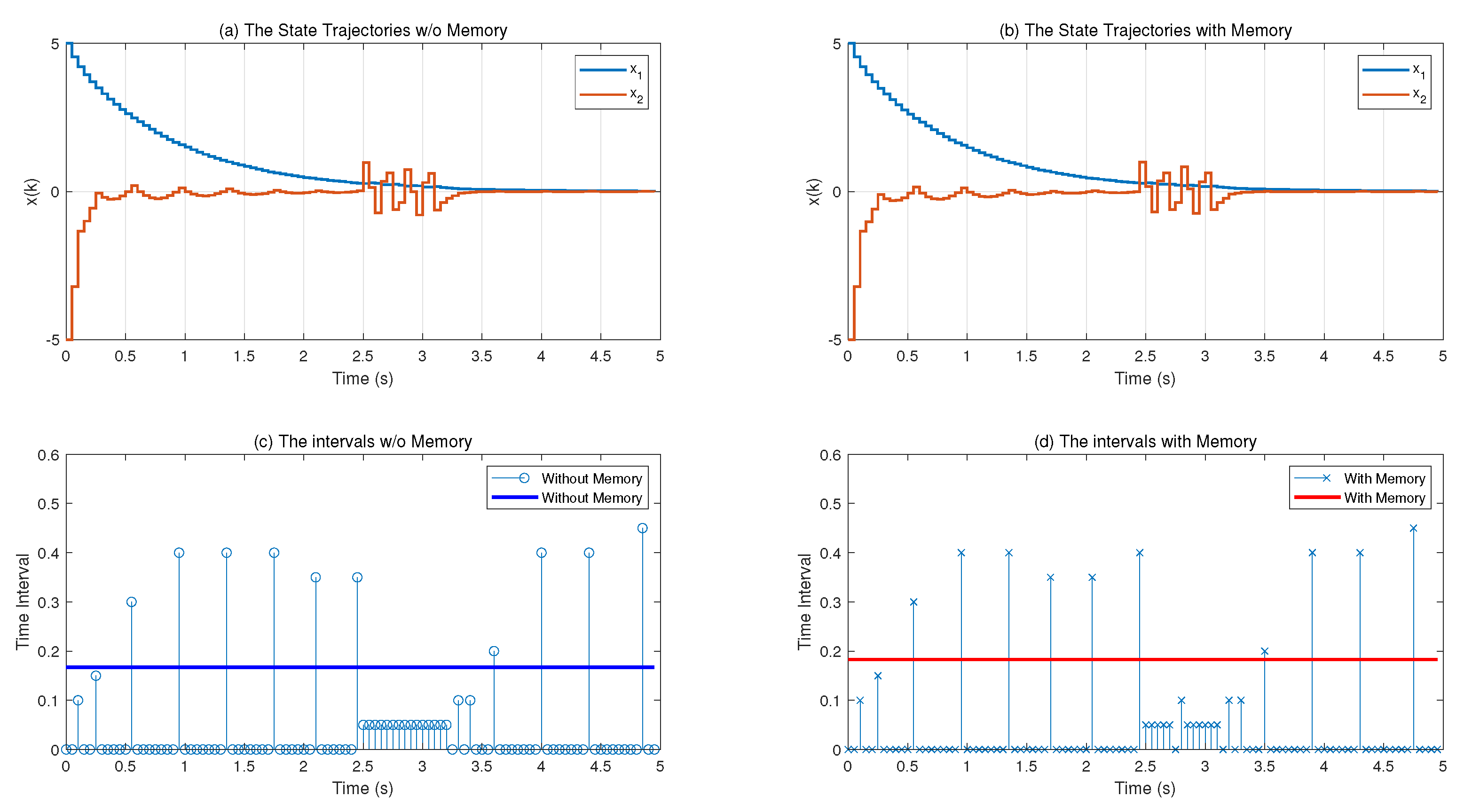
5. Numerical Examples

Three numerical examples are selected to validate the effectiveness of the proposed method.
Example (1) The 2nd-order discrete networked control system is described as follows:
x ( k + 1 ) = 0.5 0.2 0.4 0.1 x ( k ) + 0 0.1 u ( k ) + 0 1 d ( k ) , y ( k ) = 1 1 x ( k ) , z ( k ) = 1 0 0 1 x ( k ) + 0.2 0.1 u ( k ) + 0.1 0 d ( k ) .
The sampling time of the given system is chosen as 0.1 s. The maximum network delay τ m is given as 0.4 s. By using Theorem 2, the solutions are calculated as follows with the parameters b 1 = 1 , b 2 = 1 , b 3 = 1 , b 4 = 1 , ρ 1 = 0.1 , , ρ N = 0.1 , N = 3 , γ = 1.5965 ,
K 1 = 0.0449 , for N = 1 , K 1 = 0.0308 , K 2 = 0.0022 , K 3 = 0.0012 , for N = 3 .
Under the initial condition x ( 0 ) = [ 4 , 3 ] T , the system response with the given control gains is displayed in Figure 2. The outer disturbances are inserted as d ( k ) = 0.5 sin ( 0.125 π i ) cos ( 0.31 π i ) for 30 k 50 (otherwise, d ( k ) = 0 ). The state trajectories with and without memory buffer are presented at the same time for the purpose of comparison in Figure 1. The 2 memory elements are used in the example.
In Figure 3, the intervals between consecutive signals for each cases are denoted. The average transmission rate (ATR) is defined as the summation of the total consecutive signals divided by the total number of transmitted signals, which means the average interval between transmitted signals. Thus, ATR can be used as a direct indicator for the reduction of average signal transmission frequency in network. When the memory control is employed, ATR is given as 0.1750 while the value 0.1035 of ATR is for pure output feedback without memory elements. As shown in Figure 4, the memory control with 2 buffers provides remarkable improvement in the reduction of network resources. It means that the proposed scheme stabilizes the systems with much reduces signals. Approximately, 69 % larger sampling intervals are exhibited using memory control in the result.
Example (2) Another 2nd-order discrete networked control system is considered as follows:
x ( k + 1 ) = 1.1 0 1 0.5 x ( k ) + 0.5 0.1 u ( k ) + 0 1 d ( k ) , y ( k ) = 0.8 0.1 x ( k ) , z ( k ) = 1 0 0 1 x ( k ) + 0 0.1 u ( k ) + 0.3 0.1 d ( k ) .
The sampling period h is 0.25 , and an artificial delay is chosen as τ m = 0.6 . Taking parameters b 1 = 1 , b 2 = 1 , b 3 = 1 , b 4 = 1 , ρ 1 = 0.1 , ρ 2 = 0.1 , ρ 3 = 0.1 , ρ 4 = 0.1 , and γ = 2.3884 , the solutions are given for N = 1 , 2 , 3 , and 4 solving Theorem 2. The results are summarized in Table 1. The curves of state response and intervals between signals for different memory element N are shown in Figure 5, Figure 6, Figure 7 and Figure 8. From the Figures, it is shown that the proposed EMOFC is feasible under the various memory number.
Thus, for the above given controller gains, d ( k ) = s i n ( 2 π k h ) for 20 k h 25 s (otherwise d ( k ) = 0 ), and initial condition x ( 0 ) = [ 3 , 2 ] , the simulations conducted for N = 1 , 2 , 3 , and 4 are drawn. From the results, the average transmission rate is calculated using the information of accumulated total transmitted signals. The results are shown in Table 2. From Table 2 it can be noticed that the larger number of the memory is utilized, the better average transmission intervals will be. Figure 9 shows the compared average transmission rate for different memory N. It apparently displays the effect of memory elements. As memory increases, less transmitted information is transmitted, which means consuming less cost or energy.
Example (3) Decoupling of the nonlinear dynamics and linear approximation, the longitudinal motion of F-18 aircraft is represented as the following dynamic equation.
α ˙ ( t ) q ˙ ( t ) = A · α ( t ) q ( t ) + B · δ E ( t ) δ P T V ( t ) ,
where
A = 1.175 0.9871 8.458 0.8776 , B = 0.194 0.03593 19.29 3.803 .
From the discretized model, the following discrete model is constructed with corresponding matrices.
x ( k + 1 ) = 1.175 0.9871 8.458 0.8776 x ( k ) + 0.194 0.03593 19.29 3.803 u ( k ) + 19.29 3.803 d ( k ) , y ( k ) = 1 1 x ( k ) , z ( k ) = 1 0 0 1 x ( k ) + 1 0 0 0 u ( k )
The sampling time of the F-18 aircraft is 0.05 , and the τ M is chosen as 1. Applying Theorem 2 with appropriate parameters b 1 = b 2 = b 3 = 1 , b 4 = 7.7 , ρ = 0.1 , and γ = 4.9866 , the control gains are gained as follows.
( i ) Without Memory : K = 0.3604 0.0771 , Ω = 5.706 , ( ii ) With Memory : K 1 = 0.3335 0.0728 , Ω 1 = 5.2537 , K 2 = 0.0167 0.0049 , Ω 2 = 0.27665 .
For the considered system, the initial condition is taken as x ( 0 ) = [ 5 , 5 ] , and the simulations are shown in Figure 10. The blue line and the red line display the average transmission intervals. From Figure 11, one can see that the effectiveness of this proposed EMOFC method for the described aircraft system. The average intervals with and without EMOFC is 0.1827 , and 0.1672 , respectively. In average, 3 samples are unused for the stabilization of the given systems, which imply that the proposed EMOFC effectively regulates the networked control systems.

6. Conclusions

This paper proposed an summation-type event-triggering condition with event-triggered memory output feedback control (EMOFC) in the consideration of H performance. The memory output feedback control employing memorized past information of output signals is exploited to enhance the triggering intervals under novel event-triggered condition. The summation type event-triggering condition is more generalized type of condition including existing relative triggering type. The stability and control design methodology are presented under the memory control and novel triggering condition. The proposed ones are more general type of control and triggering condition covering existing methods. Throughout the numerical examples, it is shown that the proposed scheme shows off the reduction of average signal transmission frequency. Therefore, the effectiveness and improvement using memory buffer is verified. Further research could be conducted for the memory control with the network illness including missing data losses and data disorder in network. Selective-based event-triggering and adaptive-type event-trigger condition with memory are also possible as the future direction of research.

Author Contributions

Conceptualization: W.K.; software: W.K.; data curation: W.K.; writing—original draft preparation: W.K.; writing—review and editing: J.B.; supervision: J.B.; project administration: J.B.; funding acquisition: W.K. All authors have read and agreed to the published version of the manuscript.

Funding

This research was funded by Electronics and Telecommunications Research Institute (ETRI), and is currently supported by the Korean government. [20ZD1110, Development of ICT Convergence Technology for Daegu-GyeongBuk Regional Industry].

Conflicts of Interest

The authors declare that there is no conflict of interests.

References

  1. Tipsuwan, Y.; Chow, M.Y. Control methodologies in networked control systems. Control. Eng. Pract. 2003, 11, 1099–1111. [Google Scholar] [CrossRef]
  2. Lian, F.L.; Moyne, J.; Tilbury, D. Network design consideration for distributed control systems. IEEE Trans. Control. Syst. Technol. 2002, 10, 297–307. [Google Scholar] [CrossRef]
  3. Zhang, X.M.; Han, Q.L.; Yu, X. Survey on recent advances in networked control systems. IEEE Trans. Ind. Inform. 2015, 12, 1740–1752. [Google Scholar] [CrossRef]
  4. Wang, F.Y.; Liu, D. Networked Control Systems: Theory and Applications; Springer: London, UK, 2008. [Google Scholar]
  5. Bemporad, A.; Heemels, M.; Johansson, M. Networked Control Systems; Springer: Berlin/Heidelberg, Germany, 2010; Volume 406. [Google Scholar]
  6. Heemels, W.M.H.; Teel, A.R.; Van de Wouw, N.; Nesic, D. Networked control systems with communication constraints: Tradeoffs between transmission intervals, delays and performance. IEEE Trans. Autom. Control 2010, 55, 1781–1796. [Google Scholar] [CrossRef]
  7. Chen, H.; Gao, J.; Shi, T.; Lu, R. H control for networked control systems with time delay, data packet dropout and disorder. Neurocomputing 2016, 179, 211–218. [Google Scholar] [CrossRef]
  8. Xiong, J.; Lam, J. Stabilization of linear systems over networks with bounded packet loss. Automatica 2007, 43, 80–87. [Google Scholar] [CrossRef]
  9. Heemels, W.P.M.H.; Johansson, K.H.; Tabuada, P. An introduction to event-triggered and self-triggered control. In Proceedings of the 2012 IEEE 51st IEEE Conference on Decision and Control (CDC), Maui, HI, USA, 10–13 December 2012; pp. 3270–3285. [Google Scholar]
  10. Xu, Q.; Zhang, Y.; He, W.; Xiao, S. Event-triggered networked H control of discrete-time nonlinear singular systems. Appl. Math. Comput. 2017, 298, 368–382. [Google Scholar] [CrossRef]
  11. Yin, X.; Yue, D.; Hu, S. Distributed event-triggered control of discrete-time heterogeneous multi-agent systems. J. Frankl. Inst. 2013, 350, 651–669. [Google Scholar] [CrossRef]
  12. Xue, A.; Wang, H.; Lu, R. Event-based H control for discrete markov jump systems. Neurocomputing 2016, 190, 165–171. [Google Scholar] [CrossRef]
  13. Li, H.; Liao, X.; Chen, G.; Hill, D.J.; Dong, Z.; Huang, T. Event-triggered asynchronous intermittent communication strategy for synchronization in complex dynamical networks. Neural Netw. 2015, 66, 1–10. [Google Scholar] [CrossRef]
  14. de Wouw, V.; Nathan; Nešić, D.; Heemels, W.P.M.H. A discrete-time framework for stability analysis of nonlinear networked control systems. Automatica 2012, 48, 1144–1153. [Google Scholar] [CrossRef]
  15. Eqtami; Alina; Dimarogonas, D.V.; Kyriakopoulos, K.J. Event-triggered control for discrete-time systems. In Proceedings of the 2010 American Control Conference, Baltimore, MD, USA, 30 June–2 July 2010; pp. 4719–4724. [Google Scholar]
  16. Zhang, X.M.; Han, Q.L.; Ge, X.; Ding, D.; Ding, L.; Yue, D.; Peng, C. Networked control systems: A survey of trends and techniques. IEEE/CAA J. Autom. Sin. 2019, 7, 1–17. [Google Scholar] [CrossRef]
  17. Li, F.; Fu, J.; Du, D. A novel decentralised event-triggered l control for network control systems with communication delays. Int. J. Syst. Sci. 2016, 47, 3098–3115. [Google Scholar] [CrossRef]
  18. Zhang, T.; Li, J. Asynchronous event-triggered control of multi-agent systems with sigma-delta quantizer and packet losses. J. Frankl. Inst. 2016, 353, 1781–1808. [Google Scholar] [CrossRef]
  19. Shi, P.; Wang, H.; Lim, C.C. Network-based event-triggered control for singular systems with quantizations. IEEE Trans. Ind. Electron. 2015, 63, 1230–1238. [Google Scholar] [CrossRef] [Green Version]
  20. Dolk, V.; Heemels, M. Event-triggered control systems under packet losses. Automatica 2017, 80, 143–155. [Google Scholar] [CrossRef]
  21. Stöcker, C.; Lunze, J. Input-to-state stability of event-based state-feedback control. In Proceedings of the 2013 European Control Conference (ECC), Zurich, Switzerland, 17–19 July 2019; pp. 1145–1150. [Google Scholar]
  22. Wu, W.; Reimann, S.; Görges, D.; Liu, S. Event-triggered control for discrete-time linear systems subject to bounded disturbance. Int. J. Robust Nonlinear Control 2016, 26, 1902–1918. [Google Scholar] [CrossRef]
  23. Yan, S.; Zhang, G.; Li, T.; Shen, M.; Li, L. H Static Output Control of Discrete-Time Networked Control Systems with an Event-Triggered Scheme. Circuits Syst. Signal Process. 2018, 37, 553–568. [Google Scholar] [CrossRef]
  24. Liu, J.; Zha, L.; Xie, X.; Tian, E. Resilient observer-based control for networked nonlinear T–S fuzzy systems with hybrid-triggered scheme. Nonlinear Dyn. 2018, 91, 2049–2061. [Google Scholar] [CrossRef]
  25. Hu, S.; Yue, D.; Peng, C.; Xie, X.; Yin, X. Event-triggered controller design of nonlinear discrete-time networked control systems in TS fuzzy model. Appl. Soft Comput. 2015, 30, 400–411. [Google Scholar] [CrossRef]
  26. Kwon, W.; Koo, B.; Lee, S.M. Integral-based event-triggered synchronization criteria for chaotic Lur’e systems with networked PD control. Nonlinear Dyn. 2018, 94, 991–1002. [Google Scholar] [CrossRef]
  27. Tian, E.; Wang, K.; Zhao, X.; Shen, S.; Liu, J. An improved memory-event-triggered control for networked control systems. J. Frankl. Inst. 2019, 356, 7210–7223. [Google Scholar] [CrossRef]
  28. Chen, J.; Xu, S.; Ma, Q.; Li, Y.; Chu, Y.; Zhang, Z. Two novel general summation inequalities to discrete-time systems with time-varying delay. J. Frankl. Inst. 2017, 354, 5537–5558. [Google Scholar] [CrossRef]
  29. Park, J.H.; Lee, T.H.; Liu, Y.; Chen, J. Dynamic Systems with Time Delays: Stability and Control; Springer: Singapore, 2019. [Google Scholar]
  30. Boyd, S.; ElGhaoui, L.; Feron, E.; Balakrishnan, V. Linear Matrix Inequalities in System and Control Theory; SIAM: Philadelphia, PA, USA, 1994. [Google Scholar]
Figure 1. The description of network control systems with memory buffer.
Electronics 09 00779 g001
Figure 2. The state trajectories of the system with/without memory.
Electronics 09 00779 g002
Figure 3. The intervals between consecutive signals.
Electronics 09 00779 g003
Figure 4. The comparisons of the average transmission rate (ATR) with/without memory.
Electronics 09 00779 g004
Figure 5. The state trajectories of the system for N = 1.
Electronics 09 00779 g005
Figure 6. The state trajectories of the system for N = 2.
Electronics 09 00779 g006
Figure 7. The state trajectories of the system for N = 3.
Electronics 09 00779 g007
Figure 8. The state trajectories of the system for N = 4.
Electronics 09 00779 g008
Figure 9. The average transmission rate for memory.
Electronics 09 00779 g009
Figure 10. The state trajectories and intervals for with and without memory control. (a) The state response of the systems without memory control; (b) the state response of the systems with memory; (c) the intervals between transmitted signals without memory control; (d) the intervals between transmitted signals without memory control.
Electronics 09 00779 g010
Figure 11. The comparisons of the ATR with/without memory.
Electronics 09 00779 g011
Table 1. The controller gain matrices for each memory number.
MemoryController Gain K 1 Controller Gain K 2 Controller Gain K 3 Controller Gain K 4
0 K 1 = 1.5853 ---
1 K 1 = 1.5606 K 2 = 0.0050 --
2 K 1 = 1.5696 K 2 = 0.0033 K 3 = 0.0651 -
3 K 1 = 1.5786 K 2 = 0.0032 K 3 = 0.031 K 4 = 0.0318
Table 2. The average transmission rate and total transmitted signals for each memory number.
MemoryAverage Transmission RateTotal Transmitted Signal
00.310379
10.318277
20.330075
30.334574

