Abstract
An aperiodic reconfigurable microstrip antenna array is designed to serve as a DVB-T base station antenna operating in a single broadcasting channel. The antenna array is optimized at 698 MHz (center frequency of DVB-T channel 49) to concurrently achieve a particular radiation pattern shaping with high forward gain, main lobe tilting and null filling inside the service area, as well as low sidelobe level outside the service area, and low standing wave ratio at the inputs of all the array elements. To concurrently satisfy all the above requirements, both the geometry dimensions and the array feeding weights (amplitudes and phases) are optimized, thus leading to a complex multi-variable and multi-objective problem. The problem is solved by applying a recently developed particle swarm optimization (PSO) improved variant, called PSO with velocity mutation, in conjunction with the CST software package, which is employed by the PSOvm every time a full-wave analysis is required. Furthermore, all the optimization methods found in the CST environment are compared with the PSOvm. The results show that the PSOvm is capable of producing an antenna array geometry, which is closer to the predefined requirements than the geometries derived by the rest of the optimizers, in the least amount of computational time.
1. Introduction
Microstrip antenna arrays are very popular as they are low cost and easily fabricated antennas, and therefore can be used as base station antennas for broadcasting. Base station antennas must satisfy multiple requirements, which are essential in broadcasting applications [1,2,3,4,5,6]. Such requirements are: (i) high forward gain () in order to enhance reception at long distances, (ii) main lobe tilting, as the base station is usually located at places of higher altitude than the service area, (iii) null filling inside an angular sector under the main lobe, as the directional gain must stay above a specific value for proper reception, (iv) low sidelobe level () so power is not wasted outside the service area, and finally (v) low standing wave ratio () so power is not wasted inside the feeding network. In this paper, an eight-element aperiodic microstrip antenna array (AMAA) has been designed to satisfy all the above requirements at 698 MHz (center frequency of DVB-T channel 49) and more specifically to exhibit the following characteristics:
- (1)
- maximum possible at ( is the elevation angle),
- (2)
- null level ≥−20 dB with respect to the main lobe peak inside the service area defined from to (a service area),
- (3)
- dB with respect to the main lobe peak outside the service area,
- (4)
- (S-parameters ≤ dB) at the inputs of all the array elements.
The first three requirements imply a significant degradation in the directional gain when passing from the service area to the area where no service is provided. Due to this rapid gain degradation, a transition area is necessary between the previous two areas. Therefore, two transition areas, from to and from to , are defined where the gain will transition from high to low values. Consequently the 3rd requirement must be defined in two angular sectors, the first one ranging from to (sector above the main lobe) and the second one from to . The fourth requirement also helps at enhancing the bandwidth of the antenna by requesting a very low value at the channel center frequency. To satisfy all the above requirements, an AMAA with proper geometry dimensions must be found together with eight appropriate feeding weights (amplitudes and phases). The main lobe tilting is achieved by calculating the proper feeding weights and not mechanically. This is important as the array has big height, since the design frequency is 698 MHz, and it alleviates the mechanical pressure that stresses the whole structure. It is evident that this is a complex multi-variable and multi-objective problem, and such problems can be efficiently solved by using evolutionary optimization algorithms. Furthermore, the antenna studied in this paper can be turned to a reconfigurable one by implementing on-off switches with pin diodes in the feeding network in order to create different feeding weight sets and thus produce different shapes of radiation patterns that provide the desired values of gain, main lobe tilting, null filling and .
Many papers can be found in the literature where different optimization algorithms have been successfully employed to optimize antenna arrays. In Reference [7] three different PSO variants, real-number PSO, binary PSO and multi-objective PSO, are applied to different designs to obtain an optimal solution. The genetic algorithm has been employed in Reference [8] to optimize a quadrifilar helical-spiral antenna for GPS application. In Reference [9] quasi-Newton optimization has been used to design optimal implantable antennas for medical telemetry. Evolutionary techniques combined with machine learning can be found in Reference [10]. The firefly algorithm and particle swarm optimization (PSO) have been employed in Reference [11] to design a uniplanar printed triple band-rejected ultra-wideband antenna. An improved PSO algorithm has been used in Reference [12] to design an aperiodic antenna array with low SLL, minimum half power beamwidth (HPBW) and nulls in desired directions. Finally, the state-of-the-art parallel surrogate model-assisted evolutionary algorithm has been employed in References [13,14]. Since References [7,12] concern aperiodic arrays and are relevant to our paper additional discussion will be made. In Reference [7], one of the optimizations presented, concerns the design of a low 8-element aperiodic array. Only 4 parameters are optimized, specifically the spacing between the array elements and the optimization has 2 objectives, low and low null-to-null beamwidth. The radiation pattern is calculated on a theoretical basis by expressing it as the product of the array factor and the element pattern without taking into account the mutual coupling. However, the element spacing values are allowed to take large values (greater than two times the wavelength) in order to mitigate the mutual coupling. The simulated and fabricated antenna show an dB but it is only shown for to , thus, without information on the backlobes. There is also no information about the . In Reference [12], as mentioned earlier, an improved PSO variant is used to achieve low , minimum HPBW and placement of nulls in desired directions. The optimization parameters consist of the element spacings and the feeding weights (only amplitudes). The radiation pattern is expressed as the array factor, thus, not taking into account the element pattern and the mutual coupling making the results very theoretical. The radiation patterns are shown for to , and therefore, it is assumed that the was only optimized in this sector. Also, there is no information on the .
In this paper, the preferred optimizer is an improved (PSO) [15] algorithm that induces mutation to the particles’ velocities that did not improve their fitness value in the previous iteration (PSOvm) [16]. The idea behind this method is to help the particles that failed to improve their fitness value in the previous iteration, decouple from their previous velocity which actually did not lead to a fitness improvement. Thus, a perturbation is applied on their previous velocity and by doing so it is expected to help the swarm achieve better exploration and escape when being trapped to a local optimum position. The method has been proved to be very competitive against other well known optimization methods [16] and can handle effectively multi-variable and multi-objective problems as is the case of this paper (the problem consists of 26 optimization parameters and 13 objectives which will be demonstrated in later sections). PSOvm has been implemented in Matlab environment [17]. The AMAA has been fully modelled and simulated in CST Studio Suite (CST from now on) and therefore, the mutual coupling and the element pattern of each array element is considered since full wave analysis is performed. This is really important as it makes the results quite realistic. For each fitness evaluation the antenna array model is updated and a full wave analysis is performed by applying the time domain solver of CST. This solver uses the finite integration technique [18] to solve the electromagnetic problem. Therefore, at each fitness evaluation, the AMAA geometry parameters are updated and the solver simulates the updated model by calling CST built-in visual basic scripts inside the Matlab environment. It is evident that each fitness evaluation is costly in terms of resources and time but the results are highly accurate. In Figure 1 the flowchart of the optimization procedure is depicted. The computer used for the simulations was equipped with an Intel i7 5960X (eightcore) CPU, Nvidia quadro GP100 GPU (suitable for CST GPU-acceleration) with 64 GB DDR4 memory. The CST models employed by the optimization procedure consist approximately of 250,000 mesh cells (as the model changes its dimensions at each fitness evaluation, the amount of mesh cells slightly changes as well), with an average computational time equal to one minute per fitness evaluation. To the best of the authors’ knowledge, evolutionary algorithms have never been applied so far to design an AMMA for broadcasting applications in conjunction with CST.
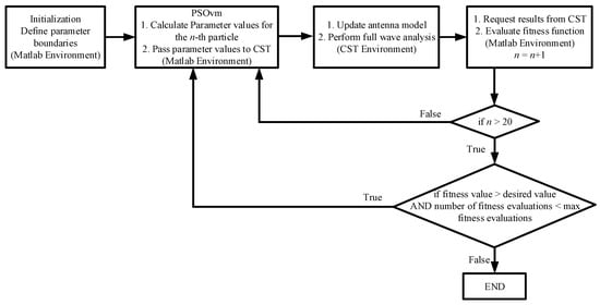
Figure 1.
Flowchart of the optimization procedure.
2. Geometry Definition
As mentioned before, CST is employed to model and simulate an eight-element AMAA for DVB-T broadcasting at 698 MHz. The feeding network is out of scope for this paper and therefore the array elements are considered to be directly excited at their input ports by sources. The inset feeding method is used in order to achieve better impedance matching to sources. The geometry of AMAA is illustrated in Figure 2 and is defined by the physical dimensions W and L of the rectangular array elements, four distances between the array elements, where (aperiodic structure), the transmission line length and width which connects each array element to its respective source, the inset depth s and the inset width g. PSOvm is employed to find the optimal values for all the above parameters. In order to help the optimization algorithm converge faster, the search space for all the geometry parameters must be confined between an upper and a lower limit. As indicated by Reference [19] the theoretical values of W and L are given by:
where c is the free space wave velocity, is the operation frequency (698 MHz in this paper), is the dielectric constant of the substrate used here, is the effective dielectric constant, and is the length reduction applied at both sides of the effective length to get physical length L. It is noted that the subscript “th” denotes the theoretical value of a variable. The values of and are respectively estimated [19] by:
where h is the substrate height (or thickness). The substrate used in this paper is Duroid RT5880LZ with and mm [20]. The thickness of the copper cladding (used in CST modeling) at both sides of the substrate is equal to 35 m [20]. By applying the above equations, we get mm and mm. It is expected that the optimal values for W and L will not deviate more than from the theoretical values given by (1) and (2) and thus, W is limited between 0.6 and 1.4 while L is limited between 0.6 and 1.4 . The distance is confined between 0.5 and 0.8 ( is the free space wavelength at 698 MHz) where the maximum is expected to be found. Since , , and are in incremental order to create the aperiodical structure of the array, we adopt the rule
where are random numbers between 0 and 0.2 . Therefore, the parameters , and are indirectly optimized through , and , respectively. The values of are confined between 0 and which helps for impedance matching. As for the width of the transmission line , the microwave theory predicts that a width of 8.4 mm will result in a transmission line of characteristic impedance equal to 50 however due to the mutual coupling between the array elements a more relaxed constraint needs to be applied in this variable and therefore the lower limit has been set at half the theoretical value (4.2 mm) and double (16.8 mm) for the upper limit. In order to calculate the theoretical value of d we use the following equations [19]:
where is the self conductance of one of the radiating slots of a microstrip patch, is the free space wavenumber, is the mutual conductance between the two radiating slots of a microstrip patch, is the Bessel function of the first kind of order zero and is the resonant input resistance of a patch. By solving (8) for we obtain the theoretical value mm and therefore s is considered to be restricted between 0.6 and 1.4 . As mentioned earlier, eight feeding weights must be found in order to achieve the desired radiation pattern. The boundaries for the amplitudes of the feeding weights () are set between 0.1 and 1 (considering an upper limit equal to ten times the lower limit), while the phases are considered to be between and . The optimal value for g according to Reference [21] is considered to be between and . As W takes different values during the optimization and g relies on W, it was decided to confine g between and of the current value of W () during the optimization process. All the boundaries for the optimization parameters are summarized in Table 1. In total, there are 26 parameters to be optimized (), thus creating a complex problem to solve.
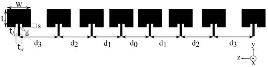
Figure 2.
Geometry of the proposed aperiodic microstrip antenna array (AMAA).

Table 1.
Optimization Parameter Limits.
3. PSO with Velocity Mutation
There are many PSO variants introduced so far in order to improve the original one. In this variant (PSOvm), the main idea is to apply perturbation to the velocities of the particles that did not improve their fitness value in the previous iteration. In this way, the swarm is protected from premature convergence and achieves greater exploration. PSOvm is based on the constriction coefficient PSO (CCPSO) and uses the gbest model. In the gbest model, one of the components used to update the velocity of a particle is influenced by the best position found by the whole swarm. The other terms are the best position found so far by the particle and its velocity at the previous iteration. By denoting the swarm size as N in a problem with Q optimization variables (Q-dimensional search space), the equations that update the velocity and position of the nth particle (), when it improves its fitness at the ith iteration, can be written as:
where and are, respectively, the qth velocity component and the qth position coordinate () of the nth particle, and are the qth coordinates of the best positions found at the end of the ith iteration by the nth particle and the whole swarm, respectively, R represents random numbers uniformly distributed within the interval (), and are, respectively, the social and the cognitive coefficient, and are both equal to 2.05, and finally is the constriction coefficient. The above equations are the original ones used in CCPSO. However, in PSOvm, if a particle fails to improve its fitness at the previous iteration, then its velocity is updated by using:
where m is the number of consecutive iterations with no fitness improvement for the nth particle. Practically, the previous velocity of a particle is multiplied by random numbers uniformly distributed in the interval when . The boundaries of this interval increase by for each consecutive fitness improvement failure. If the nth particle does not improve its fitness six consecutive times, then its velocity is updated by applying (9) and the mutation process stops. This also happens when the particle manages to improve its fitness. The term as well as the maximum value of m were found after testing PSOvm with several well known multi-dimensional mathematical fitness functions [16].
4. Optimization Results
As mentioned earlier, CST in conjunction with PSOvm is used to find the optimal values for all the parameters specified in Section 2 and Table 1. In this paper, PSOvm employs swarms of 20 particles (). This size was selected after several optimization trials and has shown promising results. As in every optimization problem, a fitness function, usually to be minimized, must be defined in order to guide the optimization algorithm towards the desired results. The expression of the fitness function used here is as follows:
where is the array gain (in dBi) at which ensures gain maximization and the desired main lobe tilting by , is the minimum gain inside the service area (from to ), represents the inside the angular sector from to , is the inside the sector defined from to and finally represents the at the input port of the nth element. The 2nd term in the fitness function ensures that the desired null level of dB is achieved inside the service area, while the 3rd and the 4th terms set the goal of dB for both the angular sectors outside the service area. Finally, the 5th term ensures that all the array elements exhibit an at their inputs (on the transmission lines edges). The angular sectors from to and from to serve as transition areas and therefore the radiation pattern inside those areas is not taken into account. The use of and functions in (12) is to help the optimization algorithm in satisfying all the requirements by ignoring any improvement in , , and when the desired values of them are reached. Finally, it must be stressed that the optimization algorithm is tasked to achieve 13 objectives in total, maximization and main lobe tilting by , null level dB, reduction in two sectors and , and 8 values by optimizing 26 parameters (described in Section 2) thus, solving a highly complex multi-objective and multi-variable problem.
The dimensions and the feeding weights of the optimized structure are shown in Table 2 and Table 3, respectively. Table 4 shows the electromagnetic characteristics of the optimized antenna in the central frequency 698 MHz and Table 5 the input impedances of the array elements. It can be seen that all the requirements have been satisfied. A high of 13.9 dBi, main lobe tilting by and null level of dB have been achieved inside the service area. The requirement inside the angular sector from to is satisfied achieving dB, as well as, the value inside the second angular sector from to achieving an of dB. Finally, the for all the array elements is below or equal to 1.2 (S-parameter dB) making the optimization completely successful. Consequently, PSOvm is a capable optimization algorithm and antennas subject to many requirements can be designed. The normalized radiation pattern of the optimized structure is illustrated in Figure 3. Figure 4 shows the S-parameters of all the array elements. It can be seen that all S-parameters are below dB thus achieving the SWR objectives. The optimized antenna exhibits an axial ratio (AR) greater than 22 dB (linear polarization) inside the service area ( to ), however, AR was not an optimization goal and is given for consistency. Finally, to verify the optimization results, the optimized structure has been rerun with a finer mesh of approximately 1,000,000 cells (compared to an average of 250,000 cells during the optimization) and the results are essentially the same.
Table 2.
Optimized Structure Dimensions.
Table 3.
Optimized Feeding Weights.
Table 4.
Optimized structure electromagnetic characteristics.
Table 5.
Input impedances of array elements.
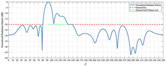
Figure 3.
Normalized radiation pattern versus elevation angle at azimuth angle . The maximum value of the normalized radiation pattern (0 dB) corresponds to the actual maximum gain of the AMAA 13.9 dBi at (main lobe tilting by ). The red dash-line shows the desired SLL outside the service area, and the green dash-line shows the desired null filling level inside the service area. The optimal radiation pattern should be below the red dash-line and above the green dash-line.
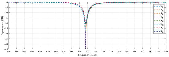
Figure 4.
S-parameters of the array elements. All S-parameters are ≤−21 dB at 698 MHz (DVB-T channel 49 center frequency) satisfying the optimization goals.
5. Comparison with Other Optimization Methods
PSOvm has been compared with all the optimization algorithms that can be found in CST: PSO, genetic algorithm (GA), trusted region framework (TRF), covariance matrix adaptation evolution strategy (CMAES), Nedler Mead simplex algorithm (NMSA), classic Powell (CP) and interpolated quasi Newton (IQN). All the optimization methods have been given a maximum of 2000 fitness evaluations in order to achieve the best result possible. Such benchmarks take a long time to be completed since, as already mentioned in earlier sections, each fitness evaluation is equal to one full wave analysis of the antenna performed by CST with an average computational time of one minute. In Table 6 we show the best result that they achieved within the fitness evaluations limit. In the last column we display the total time (in minutes) required by each method to achieve the best result. PSOvm manages to yield the best result in the least amount of time compared to the other optimization methods with TRF being close. Both PSOvm and TRF converged before hitting the limit of 2000 evaluations. The rest of the optimization methods fail to achieve multiple goals such as main lobe tilting, null level and SLL. The results of this comparison show that both PSOvm and TRF are very capable algorithms that can be used to solve complex multi-variable and multi-objective problems as is the one solved in this paper (26 variables and 13 objectives). Furthermore, it is evident that TRF is the best optimizer available found in CST.
Table 6.
Comparison of Optimization Algorithms.
6. Conclusions
An aperiodic reconfigurable antenna array that satisfies multiple requirements essential for DVB-T broadcasting, main lobe tilting, high forward gain and null filling inside the service area, low SLL outside the service area and low SWR at the input of all the array elements has been designed. The optimization problem has a significant complexity since 26 parameters have been optimized in order to best satisfy 13 goals. All the goals have been completely satisfied. The results show that the PSOvm is a robust optimization method which can be used to efficiently solve antenna optimization problems of high complexity while saving significant computational time. Also, among the optimizers found in CST, TRF proves to be not only the most efficient of them but also a very competitive one. However, the PSOvm achieves the best result in the least possible computational time compared to those derived by all the other optimizers. Since all the results in this study were obtained by using full wave analysis with CST, they reflect realistic conditions quite well. By applying on-off switches in the feeding network, the antenna array becomes a reconfigurable one, thus providing different shapes of radiation pattern according to the particular requirements that apply to a certain application.
Author Contributions
Conceptualization, Z.D.Z.; Data Curation, I.P.G. and Z.D.Z.; Methodology, Z.D.Z.; Project Administration, Z.D.Z. and T.D.X.; Software, P.I.L., N.V.K. and T.D.X.; Supervision, Z.D.Z., P.I.L., T.V.Y., N.V.K., C.S.A. and T.D.X.; Validation, I.P.G. and Z.D.Z.; Visualization, I.P.G. and Z.D.Z.; Writing—Original Draft, I.P.G.; writing—review and editing, I.P.G., Z.D.Z., P.I.L., T.V.Y., N.V.K., C.S.A., I.P.C. All authors have read and agreed to the published version of the manuscript.
Funding
This research is co-financed by Greece and the European Union [European Social Fund (ESF)] through the Operational Program “Human Resources Development, Education and Lifelong Learning” in the context of the project “Strengthening Human Resources Research Potential via Doctorate Research” under Grant MIS-5000432, implemented by the State Scholarships Foundation (IKY).
Conflicts of Interest
The authors declare no conflict of interest.
References
- Zaharis, Z.D.; Lazaridis, P.I.; Cosmas, J.; Skeberis, C.; Xenos, T.D. Synthesis of a near-optimal high-gain antenna array with main lobe tilting and null filling using Taguchi initialized invasive weed optimization. IEEE Trans. Broadcast. 2014, 60, 120–127. [Google Scholar] [CrossRef]
- Yamamoto, M.; Arai, H.; Ebine, Y.; Nasuno, M. Simple design of null-fill for linear array. In Proceedings of the International Symposium on Antennas and Propagation, Okinawa, Japan, 24–28 October 2016; pp. 410–411. [Google Scholar]
- Zaharis, Z.D. Radiation pattern shaping of a mobile base station antenna array using a particle swarm optimization based technique. Electr. Eng. 2008, 90, 301–311. [Google Scholar] [CrossRef]
- Patidar, H.; Mahanti, G.K.; Muralidharan, R. Synthesis of non-uniformly spaced linear array of unequal length parallel dipole antennas for impedance matching using QPSO. Int. J. Microw. Opt. Technol. 2017, 12, 172–181. [Google Scholar]
- Lazaridis, P.I.; Tziris, E.; Zaharis, Z.D.; Xenos, T.; Holmes, V.; Cosmas, J.P.; Glover, I.A. Comparative study of broadcasting antenna array optimization using evolutionary algorithms. In Proceedings of the 2016 URSI Asia-Pacific Radio Science Conference (URSI AP-RASC), Seoul, Korea, 21–25 August 2016; pp. 1299–1301. [Google Scholar] [CrossRef]
- Zhang, Y.; Zhang, X.Y.; Ye, L.H.; Pan, Y.M. Dual-band base station array using filtering antenna elements for mutual coupling suppression. IEEE Trans. Antennas Propag. 2016, 64, 3423–3430. [Google Scholar] [CrossRef]
- Jin, N.; Rahmat-Samii, Y. Particle swarm optimization for antenna designs in engineering electromagnetics. J. Artif. Evol. Appl. 2008, 2008, 1–10. [Google Scholar] [CrossRef]
- Zhou, D.; Gao, S.; Abd-Alhameed, R.A.; Zhang, C.; Alkhambashi, M.S.; Xu, J.D. Design and optimisation of compact hybrid quadrifilar helical-spiral antenna in GPS applications using Genetic Algorithm. In Proceedings of the 2012 6th European Conference on Antennas and Propagation (EUCAP), Prague, Czech Republic, 26–30 March 2012; pp. 1–4. [Google Scholar]
- Kiourti, A.; Nikita, K.S. Accelerated design of optimized implantable antennas for medical telemetry. IEEE Antennas Wirel. Propag. Lett. 2012, 11, 1655–1658. [Google Scholar] [CrossRef]
- Liu, B.; Aliakbarian, H.; Ma, Z.; Vandenbosch, G.A.; Gielen, G.; Excell, P. An efficient method for antenna design optimization based on evolutionary computation and machine learning techniques. IEEE Trans. Antennas Propag. 2013, 62, 7–18. [Google Scholar] [CrossRef]
- Mohammed, H.J.; Abdullah, A.S.; Ali, R.S.; Abd-Alhameed, R.A.; Abdulraheem, Y.I.; Noras, J.M. Design of a uniplanar printed triple band-rejected ultra-wideband antenna using particle swarm optimisation and the firefly algorithm. IET Microw. Antennas Propag. 2016, 10, 31–37. [Google Scholar] [CrossRef]
- Rahman, S.U.; CAO, Q.; Ahmed, M.M.; Khalil, H. Analysis of linear antenna array for minimum side lobe level, half power beamwidth, and nulls control using PSO. J. Microw. Optoelectron. Electromagn. Appl. 2017, 16, 577–591. [Google Scholar] [CrossRef]
- Liu, B.; Koziel, S. Antenna array optimization using surrogate-model aware evolutionary algorithm with local search. In Proceedings of the 2015 IEEE International Symposium on Antennas and Propagation & USNC/URSI National Radio Science Meeting, Vancouver, BC, Canada, 19–24 July 2015; pp. 1330–1331. [Google Scholar]
- Liu, B.; Akinsolu, M.O.; Ali, N.; Abd-Alhameed, R. Efficient global optimisation of microwave antennas based on a parallel surrogate model-assisted evolutionary algorithm. IET Microw. Antennas Propag. 2019, 13, 149–155. [Google Scholar] [CrossRef]
- Eberhart, R.; Kennedy, J. A new optimizer using particle swarm theory. In Proceedings of the MHS’95, Sixth International Symposium on Micro Machine and Human Science, Nagoya, Japan, 4–6 October 1995; pp. 39–43. [Google Scholar]
- Zaharis, Z.D.; Gravas, I.P.; Yioultsis, T.V.; Lazaridis, P.I.; Glover, I.A.; Skeberis, C.; Xenos, T.D. Exponential Log-Periodic Antenna Design Using Improved Particle Swarm Optimization With Velocity Mutation. Trans. Magn. 2017, 53, 1–4. [Google Scholar] [CrossRef]
- Mathworks Matlab. Available online: https://www.mathworks.com (accessed on 12 May 2018).
- CST Studio Suite. Available online: https://www.3ds.com/products-services/simulia/products/cst-studio-suite/ (accessed on 16 June 2019).
- Balanis, C.A. Antenna Theory: Analysis and Design; Wiley-Interscience: New York, NY, USA, 2005; pp. 816–826. [Google Scholar]
- Rogers Corporation. Available online: https://www.rogerscorp.com (accessed on 2 February 2020).
- Matin, M.A.; Sayeed, A.I. A design rule for inset-fed rectangular microstrip patch antenna. WSEAS Trans. Commun. 2010, 9, 63–72. [Google Scholar]


© 2020 by the authors. Licensee MDPI, Basel, Switzerland. This article is an open access article distributed under the terms and conditions of the Creative Commons Attribution (CC BY) license (http://creativecommons.org/licenses/by/4.0/).