Field-Oriented Driving/Braking Control for Electric Vehicles


Abstract
:1. Introduction
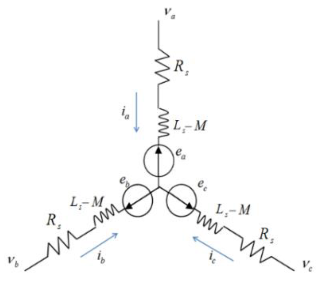
2. PMSM Model
3. Control Strategy
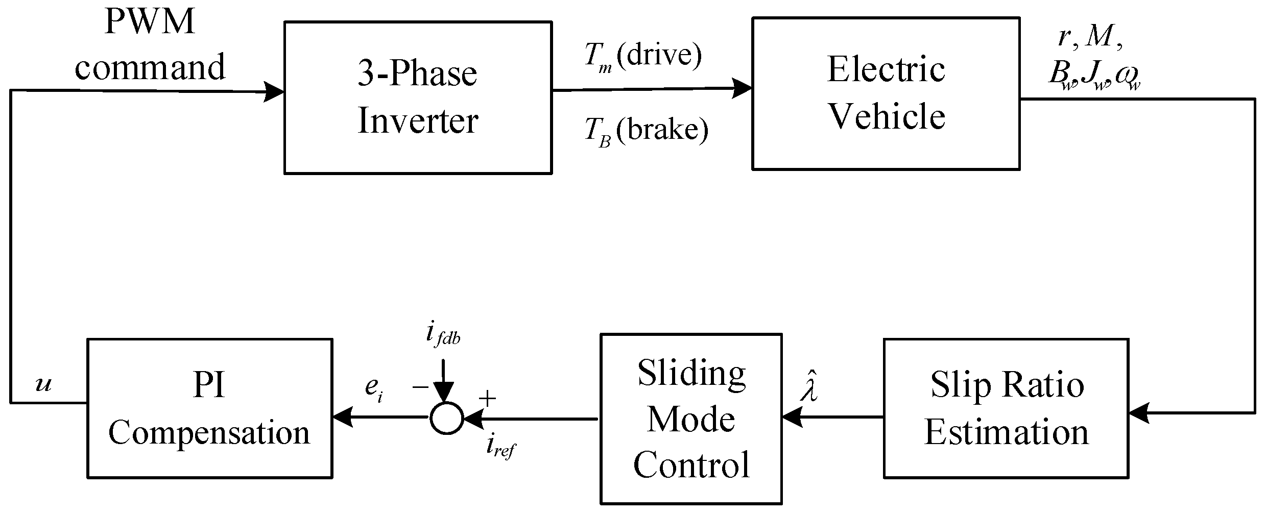
3.1. System Architecture
3.2. Driver Design
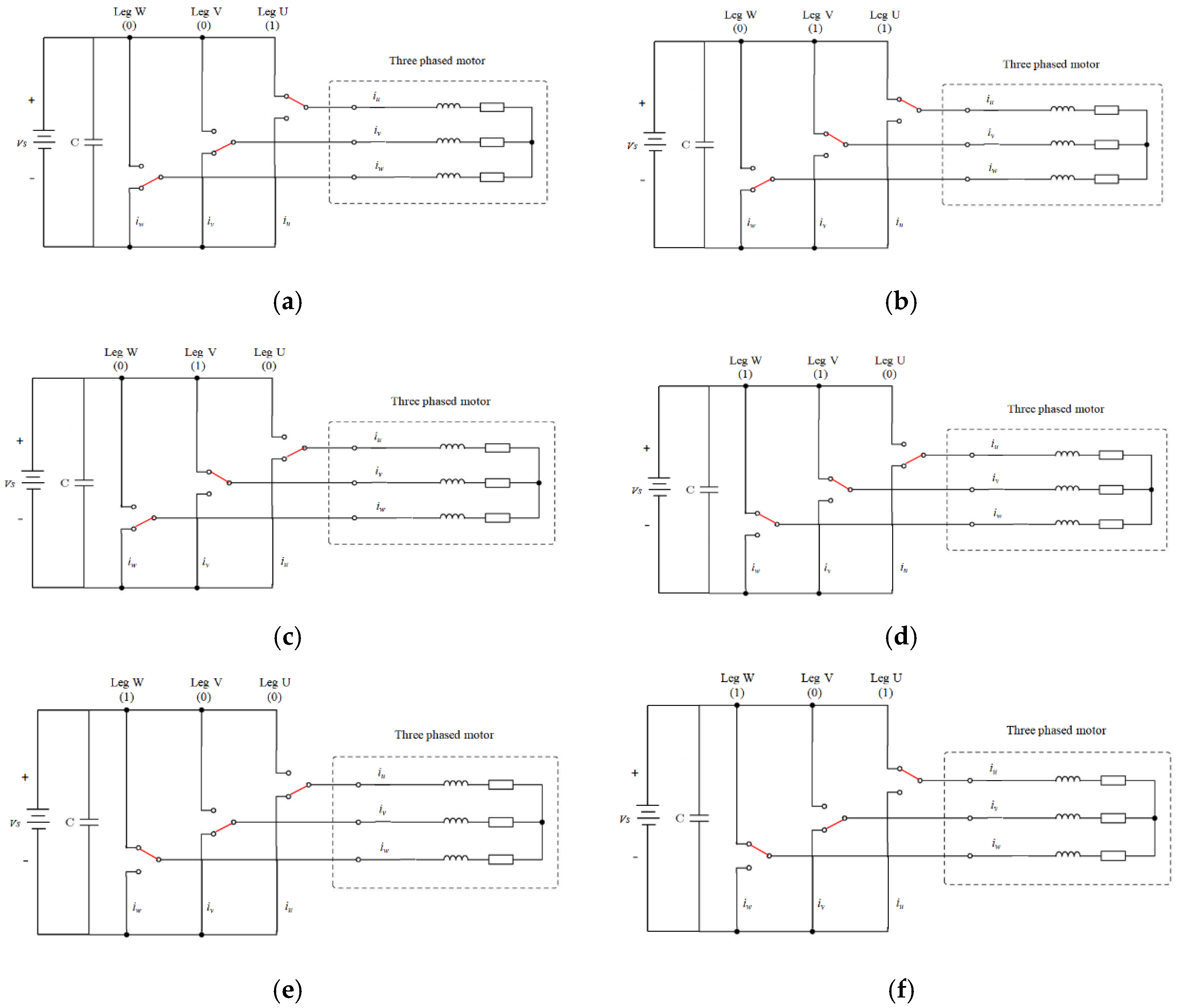
3.3. Brake Control Design
4. Implementation
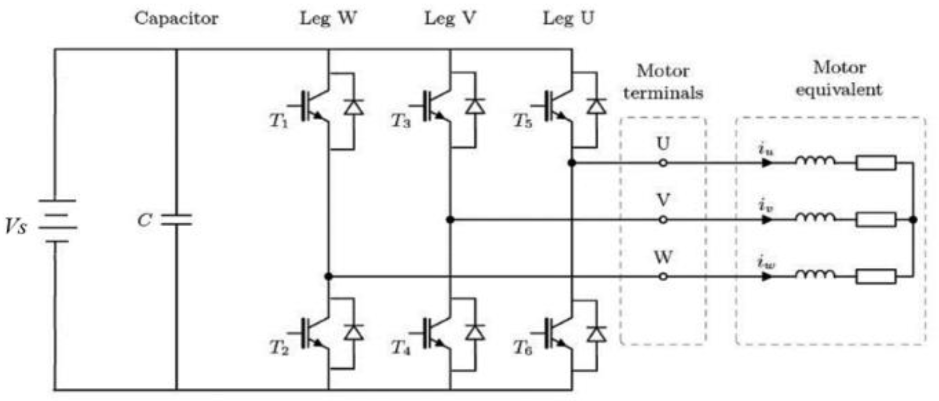
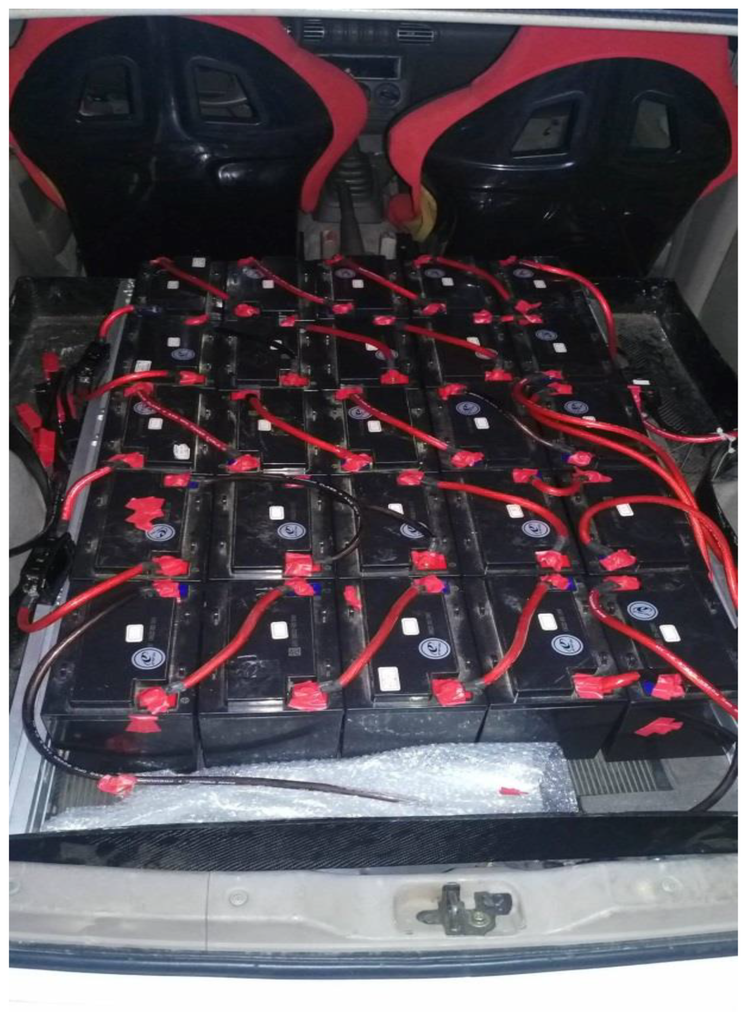
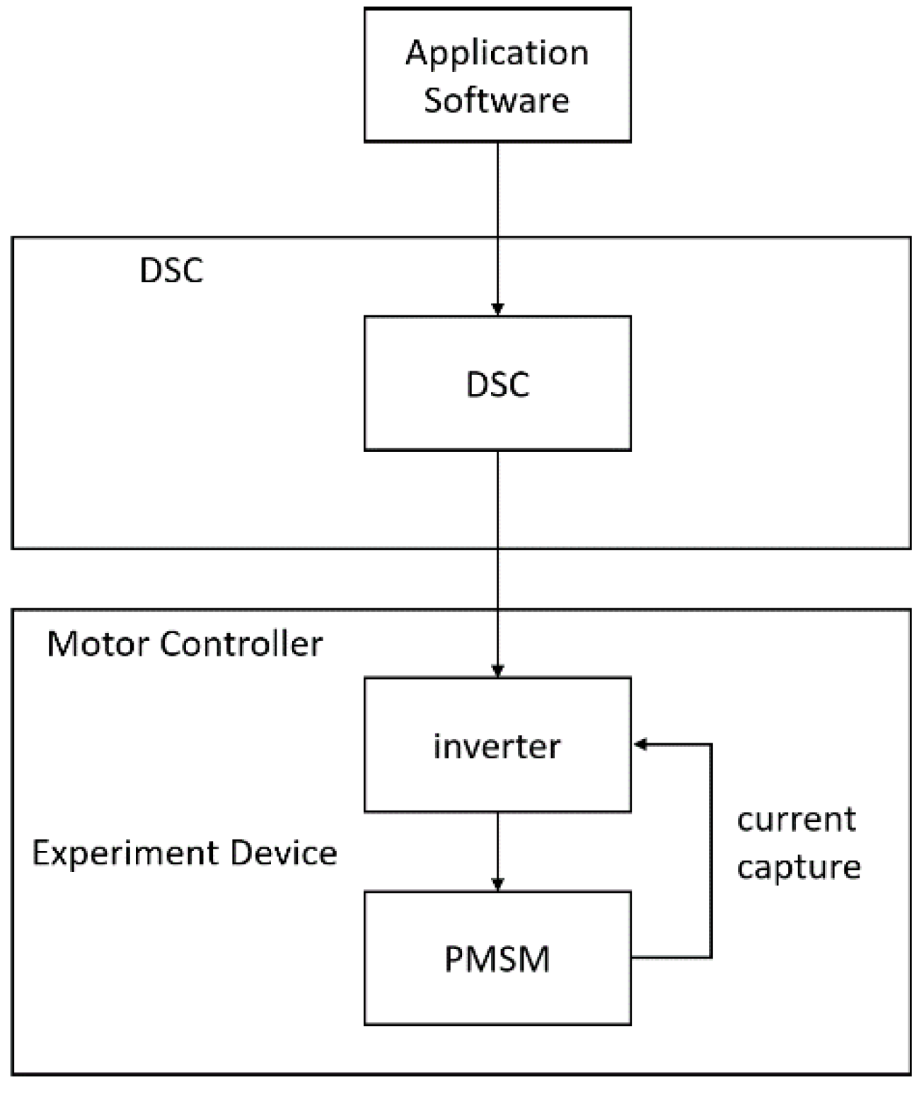
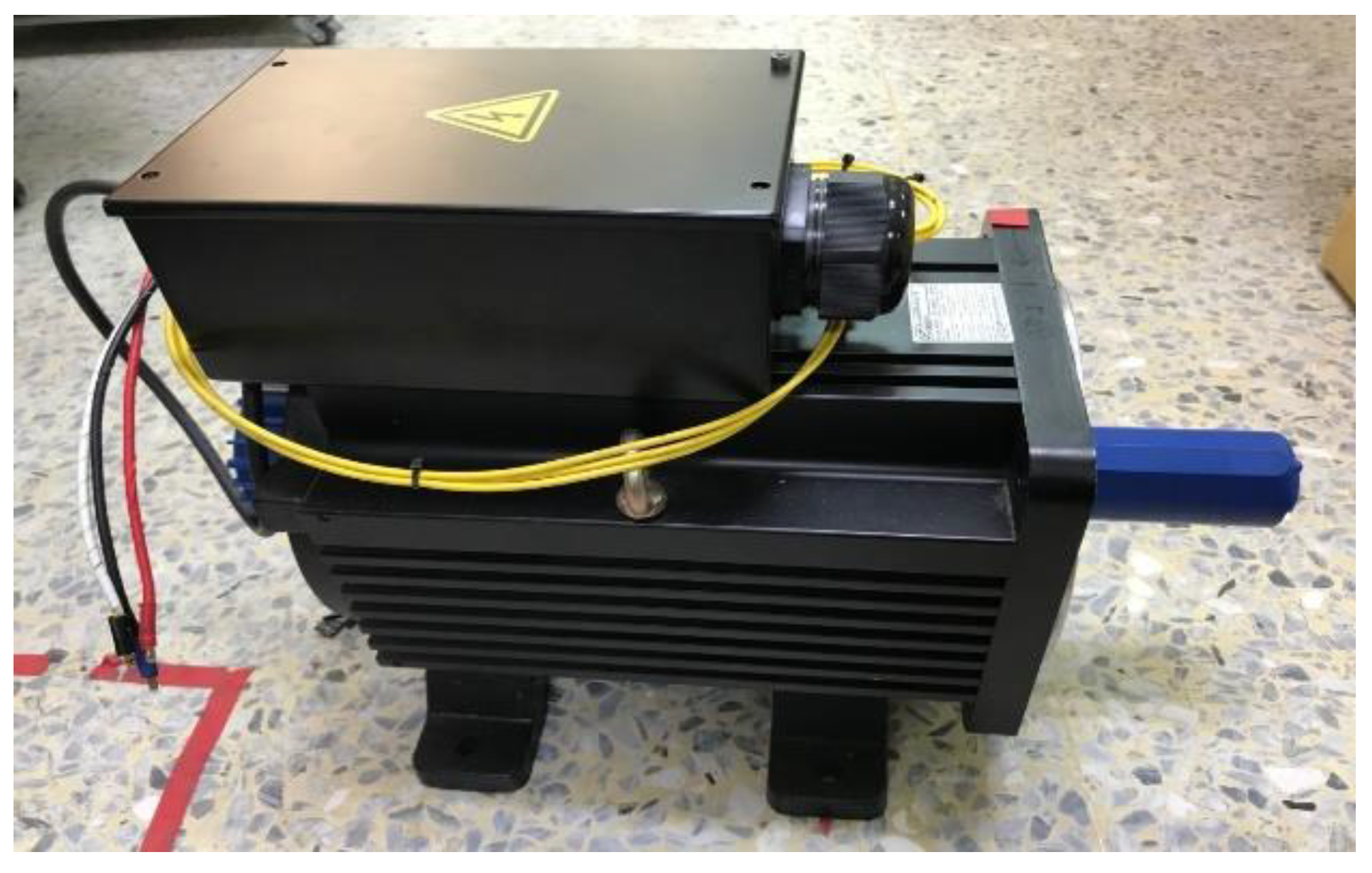
4.1. Hardware Design
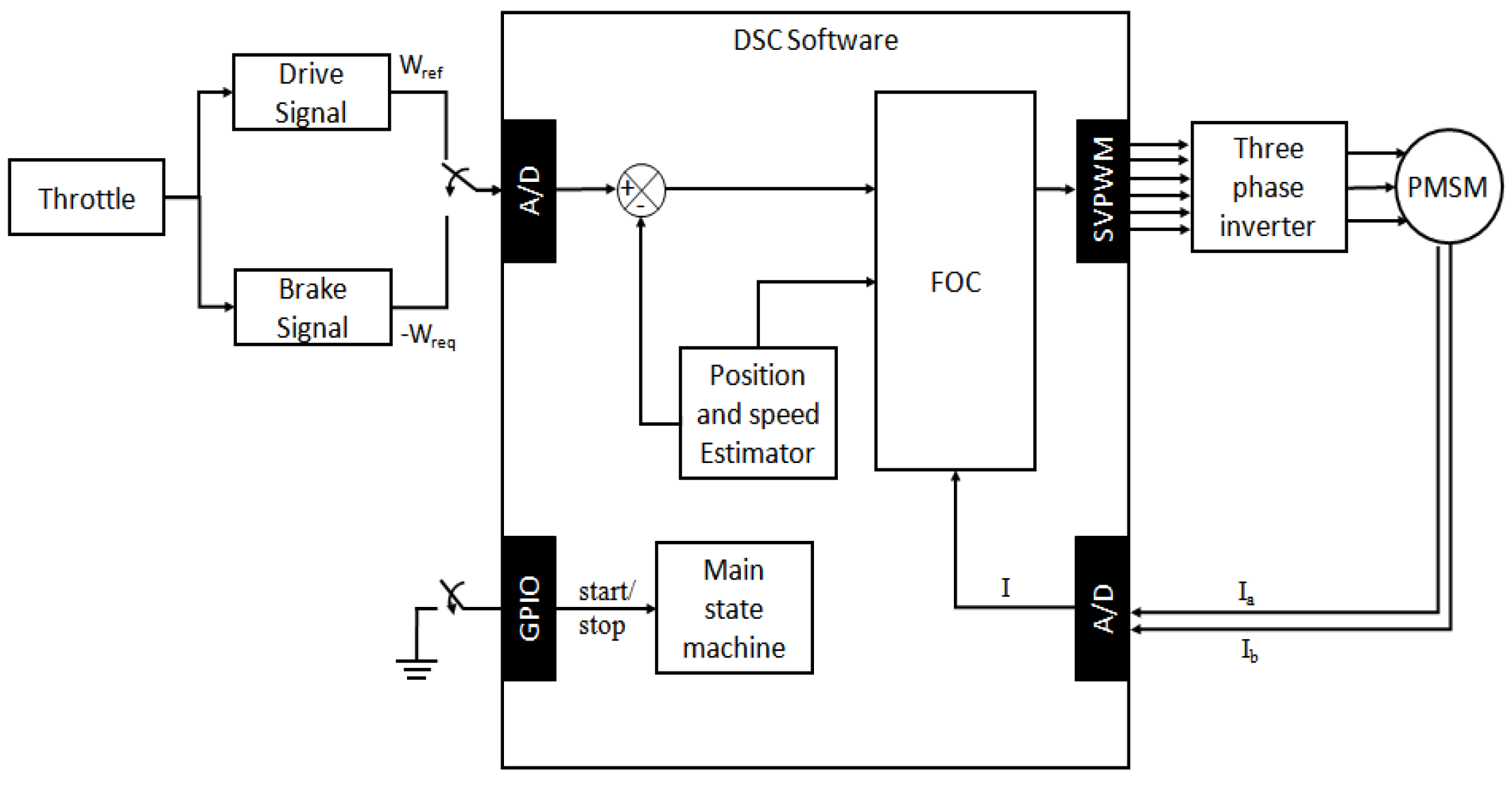
4.2. Software Design
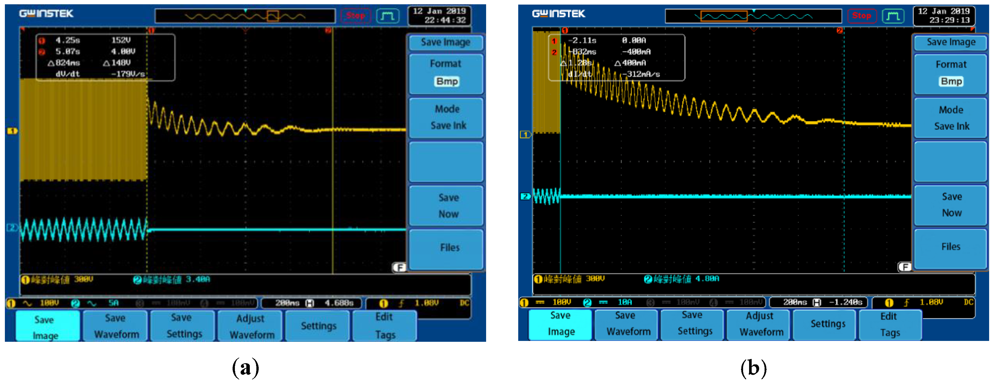
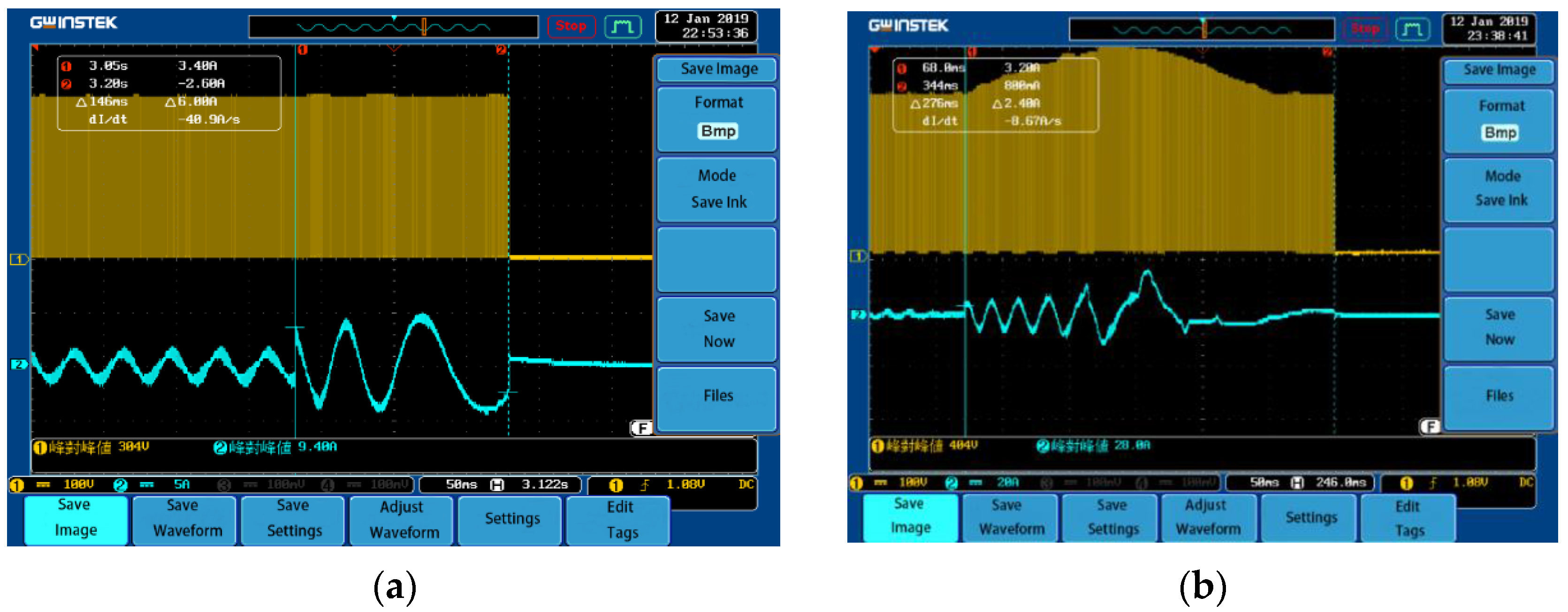
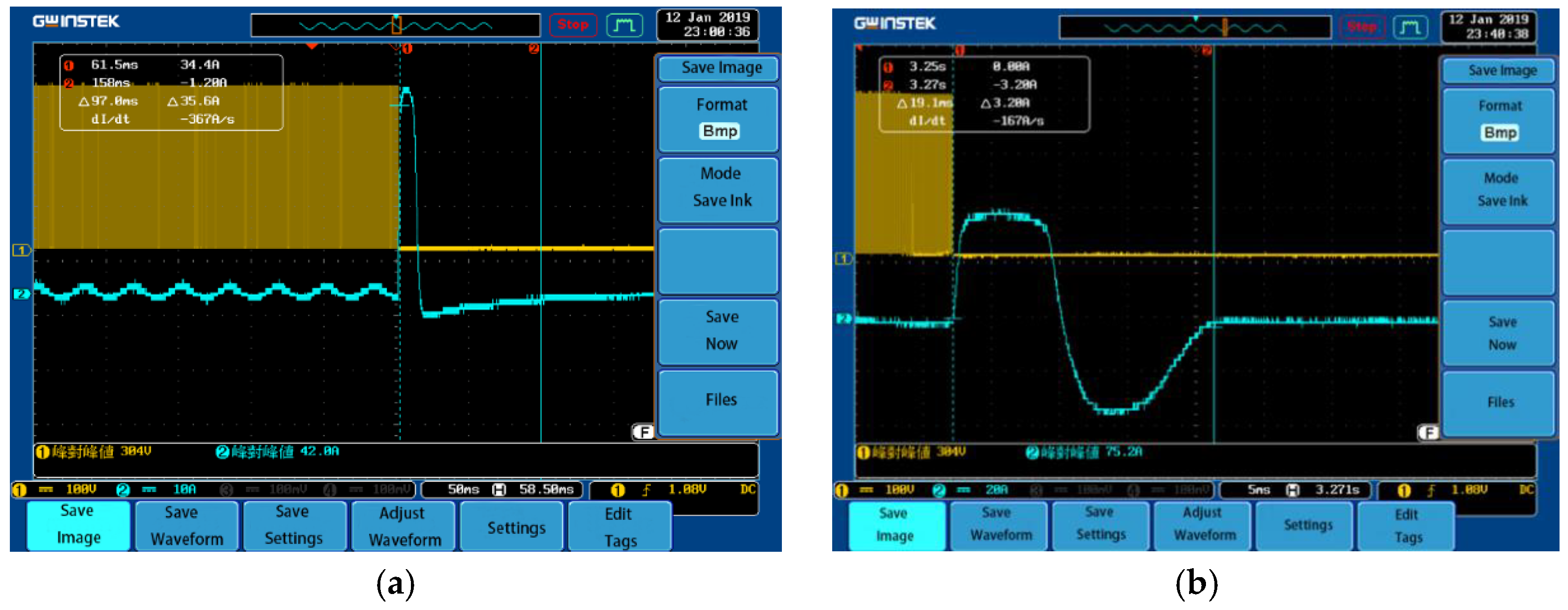
5. Representative Results
6. Conclusions
7. Patents
Author Contributions
Funding
Conflicts of Interest
References
- Tzortzis, G.; Amargianos, A.; Piperidis, S.; Koutroulis, E.; Tsourveloudis, N.C. Development of a compact regenerative braking system for electric vehicles. In Proceedings of the Mediterranean Conference on Control and Automation, Torremolinos, Spain, 16–19 June 2015; pp. 102–108. [Google Scholar]
- Luo, N.; Jiang, J.; Yu, A. Research on the control strategy of the regenerative braking system. In Proceedings of the International Conference on Mechatronics and Control, Harbin, China, 3–5 July 2014; pp. 2514–2517. [Google Scholar]
- Itani, K.; Bernardinis, A.D.; Khatir, Z.; Jammal, A.; Oueidat, M. Regenerative braking modeling, control, and simulation of a hybrid energy storage system for an electric vehicle in extreme conditions. IEEE Trans. Transp. Electrif. 2016, 2, 465–479. [Google Scholar] [CrossRef]
- Itani, K.; de Bernardinis, A.; Khatir, Z.; Jammal, A. Optimal traction and regenerative braking reference current synthesis for an IPMSM motor using three combined torque control methods for an electric vehicle. In Proceedings of the IEEE Transportation Electrification Conference & Expo, Dearborn, MI, USA, 27–29 June 2016; pp. 1–6. [Google Scholar]
- Fajri, P.; Lee, S.; Prabhala, V.A.K.; Ferdowsi, M. Modeling and integration of electric vehicle regenerative and friction braking for motor/dynamometer test bench emulation. IEEE Trans. Veh. Technol. 2016, 65, 4264–4273. [Google Scholar] [CrossRef]
- Zhang, X.; Gohlich, D.; Li, J. Energy-efficient toque allocation design of traction and regenerative braking for distributed drive electric vehicles. IEEE Trans. Veh. Technol. 2018, 67, 285–295. [Google Scholar] [CrossRef]
- Pengyu, W.; Qingnian, W.; Wangwei; Naiwei, Z. The affect of motor efficiency on regenerative braking at low-speed stage. In Proceedings of the International Conference on Energy and Environment Technology, Guilin, China, 16–18 October 2009; pp. 388–391. [Google Scholar]
- Gokce, C.; Ustun, O.; Yeksan, A.Y. Dynamics and limits of electrical braking. In Proceedings of the International Conference on Electrical and Electronics Engineering, Bursa, Turkey, 28–30 November 2013; pp. 268–272. [Google Scholar]
- Cody, J.; Göl, Ö.; Nedic, Z.; Nafalski, A.; Mohtar, A. Regenerative braking in an electric vehicle. Zesz. Probl. –Masz. Elektr. 2009, 81, 113–118. [Google Scholar]
- Lin, C.L.; Yang, M.Y.; Chen, E.P.; Chen, Y.C.; Yu, Y.C. Novel antilock braking control system for electric vehicles. IET J. Eng. 2018, 2018, 60–67. [Google Scholar]
- Lin, W.C.; Lin, C.L.; Hsu, P.M.; Wu, M.T. Realization of Anti-Lock braking strategy for electric scooters. IEEE Trans. Ind. Electron. 2014, 61, 2826–2833. [Google Scholar] [CrossRef]
- Lin, C.L.; Tu, C.H.; Liu, M.K. Method of Adjus Electro-Magnetic Braking Force for Electric Bikes. Taiwan Patent No. I626190, 11 June 2018. [Google Scholar]
- Lin, C.L.; Hsieh, M.C.; Chen, T.H. Integrated driving and braking control unit for electric bikes. SAE Int. J. Veh. Dyn. Stab. NVH 2018, 2, 223–242. [Google Scholar] [CrossRef]
- Chen, Y.C.; Tu, C.H.; Lin, C.L. Integrated electromagnetic braking/driving control for electric vehicle using fuzzy inference. IET Electr. Power Appl. 2019, 13, 1014–1021. [Google Scholar] [CrossRef]
- Zambada, J.; Deb, D. Sensorless Field Oriented Control of a PMSM; AN1078 of Microchip Technology Inc.: Chandler, AZ, USA, 2010; pp. 1–28. [Google Scholar]
- Genduso, F.; Miceli, R.; Rando, C.; Galluzzo, G.R. Back EMF sensorless-control algorithm for high-dynamic performance PMSM. IEEE Trans. Ind. Electron. 2010, 57, 2092–2100. [Google Scholar] [CrossRef]
- Jiang, J.; Holtz, J. An efficient braking method for controlled ac drives with a diode rectifier front end. IEEE Trans. Ind. Appl. 2001, 37, 1299–1305. [Google Scholar] [CrossRef]
- Enrique, L. Carrillo Arroyo, Modeling and Simulation of Permanent Magnet Synchronous Motor Drive System. Master’s Thesis, University of Puerto Rico, San Juan, Puerto Rico, 2006. [Google Scholar]
- Ruohu, S. Demagnetization of Permanent Magnets in Electrical Machines; Doctoral School of Energy-and Geo-Technology: Kuressaare, Saaremaa, Estonia, 2007; pp. 181–185. [Google Scholar]
- Fu, W.N.; Ho, S.L. Dynamic demagnetization computation of permanent magnet motors using finite element method with normal magnetization curves. IEEE Trans. Appl. Supercond. 2010, 20, 851–855. [Google Scholar] [CrossRef]
- Liu, S.M.; Tu, C.H.; Lin, C.L.; Liu, V.T. Video demonstration: Test of Driving at the NCHU Campus (24°07′26.7″ N 120°40′30.2″ E/24.124083° N 120.675056° E). Available online: https://youtu.be/LWUFJMBLu8s (accessed on 3 September 2020).
- Liu, S.M.; Tu, C.H.; Lin, C.L.; Liu, V.T. Video demonstration: Test of Brake on the Plane. Available online: https://youtu.be/1QbzRgUIt_Q (accessed on 3 September 2020).
- Liu, S.M.; Tu, C.H.; Lin, C.L.; Liu, V.T. Video demonstration: Test of Engine Brake (Generated by the Motor) on the Down Ramp Lane-Front View. Available online: https://youtu.be/quXreRd1Ofc (accessed on 3 September 2020).
- Liu, S.M.; Tu, C.H.; Lin, C.L.; Liu, V.T. Video demonstration: Test of Engine Brake (Generated by the Motor) on the Down Ramp Lane-Rear View. Available online: https://youtu.be/X0m6POyrdO4 (accessed on 3 September 2020).
- Liu, S.M.; Tu, C.H.; Lin, C.L.; Liu, V.T. Video demonstration: Test of Driving on the Climbing Lane-Front View. Available online: https://youtu.be/rmoI10k55cs (accessed on 3 September 2020).
- Liu, S.M.; Tu, C.H.; Lin, C.L.; Liu, V.T. Video demonstration: Test of Driving on the Climbing Lane-Rear View. Available online: https://youtu.be/zpTgKn-jnww (accessed on 3 September 2020).


| Model | LDSM230-D |
|---|---|
| Number of poles | 8 |
| Power (kw) | 15 |
| Torque (Nm) | 90.1 |
| NR (RPM) | 1500 |
| Max current (A) | 55.5 |
| Ke (V) | 92.4 |
| Back-eEMF type | Sine wave |
| Braking Condition (rpm) | Braking Type | Peak Current (A) | Peak Voltage (V) |
|---|---|---|---|
| 450 | Neutral sliding | 3.4 | 300 |
| 450 | Short-circuit braking | 42 | 304 |
| 450 | FOC reverse-braking | 9.4 | 304 |
| 950 | Neutral sliding | 4.8 | 300 |
| 950 | Short-circuit braking | 75.2 | 304 |
| 950 | FOC reverse-braking | 28 | 404 |
© 2020 by the authors. Licensee MDPI, Basel, Switzerland. This article is an open access article distributed under the terms and conditions of the Creative Commons Attribution (CC BY) license (http://creativecommons.org/licenses/by/4.0/).
Share and Cite
Liu, S.-M.; Tu, C.-H.; Lin, C.-L.; Liu, V.-T. Field-Oriented Driving/Braking Control for Electric Vehicles. Electronics 2020, 9, 1484. https://doi.org/10.3390/electronics9091484
Liu S-M, Tu C-H, Lin C-L, Liu V-T. Field-Oriented Driving/Braking Control for Electric Vehicles. Electronics. 2020; 9(9):1484. https://doi.org/10.3390/electronics9091484
Chicago/Turabian StyleLiu, Shang-Ming, Chia-Hung Tu, Chun-Liang Lin, and Van-Tsai Liu. 2020. "Field-Oriented Driving/Braking Control for Electric Vehicles" Electronics 9, no. 9: 1484. https://doi.org/10.3390/electronics9091484
APA StyleLiu, S.-M., Tu, C.-H., Lin, C.-L., & Liu, V.-T. (2020). Field-Oriented Driving/Braking Control for Electric Vehicles. Electronics, 9(9), 1484. https://doi.org/10.3390/electronics9091484