
Design of a Labriform-Steering Underwater Robot Using a Multiphysics Simulation Environment
by
 , , , and
Daniele Costa
1 ,
,
Cecilia Scoccia
1 ,
,
Matteo Palpacelli
1,*,
Massimo Callegari
1 and
and
David Scaradozzi
2 1
Department of Industrial Engineering and Mathematical Sciences, Polytechnic University of Marche, 60131 Ancona, Italy
2
Department of Information Engineering, Polytechnic University of Marche, 60131 Ancona, Italy
*
Author to whom correspondence should be addressed.
Robotics 2022, 11(1), 11; https://doi.org/10.3390/robotics11010011
Submission received: 22 November 2021
/
Revised: 18 December 2021
/
Accepted: 4 January 2022
/
Published: 7 January 2022
(This article belongs to the Special Issue Kinematics and Robot Design IV, KaRD2021)
Abstract
:Bio-inspired solutions devised for Autonomous Underwater Robots are currently investigated by researchers as a source of propulsive improvement. To address this ambitious objective, the authors have designed a carangiform swimming robot, which represents a compromise in terms of efficiency and maximum velocity. The requirements of stabilizing a course and performing turns were not met in their previous works. Therefore, the aim of this paper is to improve the vehicle maneuvering capabilities by means of a novel transmission system capable of transforming the constant angular velocity of a single rotary actuator into the pitching–yawing rotation of fish pectoral fins. Here, the biomimetic thrusters exploit the drag-based momentum transfer mechanism of labriform swimmers to generate the necessary steering torque. Aside from inertia and encumbrance reduction, the main improvement of this solution is the inherent synchronization of the system granted by the mechanism’s kinematics. The system was sized by using the experimental results collected by biologists and then integrated in a multiphysics simulation environment to predict the resulting maneuvering performance.
1. Introduction
The locomotion of aquatic animals has attracted the attention of biologists and engineers for a long time, and the last thirty years have witnessed a significant growth in the study of the comparative biomechanics of motion through water. The attempts to design machines, such as autonomous underwater vehicles (AUVs) capable of moving similar to biological swimmers are inspired by the superior performance of marine animals and fish in terms of both efficiency and maneuverability. Several prototypes of bio-inspired robots can thus be mentioned, whereas an extensive review is presented in [1]. The possibility of exploiting the swimming modes that fish have evolved over thousands of years requires insight into the fluid mechanic principles underlying aquatic animal locomotion. According to swim mechanics, propulsive thrust is generated from the momentum transfer due to the relative motion between the fish body and the surrounding water. Figure 1 illustrates the terminology used to identify morphological features commonly used in the literature. Most fish generate thrust by bending their bodies into a backward-moving propulsive wave that extends to their caudal fin, a type of swimming classified as Body and Caudal Fin (BCF) locomotion [1]. Other fish have developed alternative mechanisms that involve the use of their median and pectoral fins: these swimming modes are classified as Median and Paired Fin (MPF) locomotion. An estimated 15% of fish families employ non-BCF modes as their primary motion system, whereas those that rely on BCF modes for propulsion employ MPF modes for maneuvering and stabilization [2].
In the last few years, the authors of this work designed, prototyped, and experimentally validated [3] a series of bio-inspired vehicles for both research and educational purposes: the robot in [4] is driven by an oscillating plate shaped such as a caudal fin and is hinged to the rigid forebody; this is the least efficient locomotion principle among the BCF swimming modes [1]; however, since the number of moving parts is very limited, the resulting system is inexpensive and easy to fabricate and seal. The search for higher propulsive efficiency has forced the authors to further improve their design by moving to the undulating tail presented in [5]: in the latter, the links of the transmission mechanism are driven by cam joints connected to a piecewise flexible shaft actuated by a single rotary actuator. The adopted swimming mode represents a compromise choice in terms of efficiency and maximum speed for an underwater robot propelled by a biomimetic thruster. However, the requirements of stabilizing a course and performing stationary turns have not been met yet. As a matter of fact, the robot in [5] is able to swim following a straight path, whereas it lacks any capability to adjust its course as well as steer, under both stationary and dynamic conditions. Therefore, before moving to the prototyping and testing phases, the authors aim to fulfill those necessities by improving their design, which is the focus of this paper. Particularly, the purpose of this work is to present a bio-inspired maneuvering device which exploits the momentum transfer mechanism of MPF locomotion to generate the steering torque. The system was designed so as to be integrated in the robot described in [5]; therefore, the final prototype will rely on BCF swimming modes for forward propulsion, whereas the pectoral fins will be deployed whenever a course correction is required. Ultimately, the concept that drove authors’ research since their first work [4] is to exploit the best opportunities offered by nature to improve the speed and maneuverability of AUVs.
As stated before, MPF swimming modes are widespread among aquatic animals for maneuvering and stabilization; particularly, in labriform mode, the steering torque is generated through the pectoral fin motion. Two alternative oscillatory movement types were identified [6]: a rowing action based on drag forces and a flapping action due to lift generation similar to birds flying. In the former, the rowing action consists of two phases [6]: the power stroke of Figure 2a, where the fins move posteriorly at a high attack angle and high speed, and the recovery stroke of Figure 2b, where the fins are feathered at a near-zero angle of attack to reduce resistance while they are brought forward at low speed. On the contrary, in the lift-based mode displayed in Figure 2c, the propulsive force is always normal to the direction of the fin motion; as a result, no recovery stroke is necessary. According to [6,7], the drag-based method is more efficient at low speeds, whereas lift-based maneuvering requires higher velocities to generate significant forces. Due to the necessity to perform even stationary turn maneuvers, drag-based momentum transfer mechanism was chosen by the authors of this work.
According to the literature, the potential for building stabilization and maneuvering devices based on pectoral fins motion has already been investigated by biologists [8,9] and researchers in the underwater robotic field: in [10], two concave-shape fins were connected to a servomotor arm sliding on a pair of parallel shafts fixed at the center of a pool. Due to the concave shape of the fins, the propulsive forces generated by the power strokes overcame the ones generated by the recovery strokes. The authors tested several fin-oscillations angles, whereas the optimum oscillation range was obtained for each power-to-recovery ratio in order to achieve the maximum thrust. Five values of the power-to-recovery ratio were tested, and the maximum thrust was obtained for a moderate ratio of the power-to-recovery stroke, i.e., 3:1. A similar driving system was adopted in [11,12,13]: in [11], each pectoral fin was driven by a couple of servomotors. The authors employed this architecture to obtain different types of motion: rowing, flapping, and hovering. The performance of the proposed solution was investigated experimentally by varying the fin flapping frequency and amplitude, and the optimal behavior was found as a function of the Strouhal number, a parameter commonly used to characterize flow–oscillation phenomena. In [12], the authors reduced the number of servomotors by designing the fin driving system in a symmetrical way. Experimental tests were performed to examine two different maneuvering conditions: the steering force was initially generated through asymmetrical tail undulations, whereas the pectoral fins were kept still in the feathering position; later, both the tail and the pectoral fins cooperated with the turn maneuver, improving the performance in terms of the turnabout radius and velocity. Turning characteristics were also measured in [13], where a robotic fish was driven by two degrees of freedom (DOF) pectoral fins. As in [12], the results of the numerical simulations and the experiments showed that the fastest turning speed was achieved when the robotic fish was cooperatively propelled by both the fins and the tail; the pectoral fins are capable by themselves to turn the robotic fish on the spot, but the resulting angular speed is the smallest. Finally, an active–passive solution was devised in [14,15], where the second servomotor was replaced by a flexible mechanism. Here, the authors presented a dynamic model for a robotic fish incorporating the proposed steering device. Experimental tests were performed by varying the geometric and kinematic parameters of the fin motion, whereas the flexibility effect was also investigated by using different compliant joints. The obtained measurements ultimately showed that maximum efficiency was achieved, as the Strouhal number was within the optimal range reported in the literature and was observed by researchers in the biological counterparts.
The robotic fish in [10,11,12,13] adopted drag-based labriform locomotion for stabilization and maneuvering. Here, the yawing–pitching oscillation of the pectoral fins was driven by a couple of servomotors connected in series: the first one, attached to the robot forebody, drives the rowing rotation around the yaw axis of the vehicle; whereas the second one, connected to the pectoral fin, allows the latter to trim its attitude and is used for feathering. Although this solution is simple to manufacture, the main disadvantages of a direct drive are the number of motors and the necessity to synchronize their rotations to generate the yawing–pitching oscillation presented in [6]. Position control is then necessary in order to comply with a non-linear function of time and to maintain the constant phase shift between the fin rotation components. Moreover, each servomotor must be accurately sealed, while watertight connections must be mounted both on the joint shafts and on the electrical cables, thus increasing the structure inertia, encumbrance, and possibility of failure.
On the basis of the aforementioned factors, the aim of the present work is to design a novel transmission system driven by a single rotary actuator that is capable of driving the pectoral fins of the robotic fish [5] while exploiting the drag-based momentum transfer mechanism of labriform locomotion. Aside from inertia and encumbrance reduction, the main improvement of this solution is the inherent synchronization of the system, meaning left and right fins as well as their individual rotation components. In fact, the phase shifts and the oscillation frequencies will remain constant by the mechanical constraints of the transmission system. Waterproofing issues will also be minimal because the section housing the pectoral fin mechanism will be fully flooded and only one actuator will need sealing.
2. Materials and Methods
The geometric and inertial features of the biomimetic robot designed in [5] were modeled after a mackerel (Scomber Scombrus) [16]. Fish belonging to the Scombridae family possess a streamlined body with a homocercal caudal fin and can achieve the highest speed among BCF swimmers. As stated before, fish relying on BCF modes for propulsion employ MPF modes for maneuvering and stabilization. Inspired by nature, the aim of the authors was to successfully replicate this behavior in an artificial device. The final assembly is a 2:1 scale of the biological mackerel: the robot is 800 mm long and its tail spans the last 300 mm.
2.1. Mechanics of Drag-Based Labriform Swimming and Blade-Element Theory
A complete analysis of the mechanics of drag-based labriform locomotion is beyond the scope of this work, and extensive reviews are presented in [17,18]. However, in order to size the transmission system devised in this paper, the following assumptions are necessary [6]:
- Drag force is due to pressure drag only, whereas the effects of viscosity are negligible.
- During the power stroke, the distal two-thirds of the fin are perpendicular to the horizontal plane.
- The rowing rotation around the fish yaw axis is about 90 degrees.
- At the end of the power stroke, as the fin moves forward, its distal two-thirds form a small angle with the horizontal plane (about 10–20 degrees).
- The power stroke is about three times faster than the recovery stroke.
- A blade-element approach is used to analyze pectoral fin mechanics in drag-based labriform swimming.
A schematic diagram showing pectoral fin positions and orientation during a beat cycle is shown in Figure 3a together with a typical blade-element during a power stroke, Figure 3b. Here, progressive numbers were used to show the consecutive positions of the fins during both power and recovery strokes. Blade-element theory is a mathematical process originally conceived to predict the behavior of propellers: their blades are broken down into small parts and the forces acting on each one of these elements are calculated. These forces are then integrated along the entire blade and over one revolution in order to compute the thrust and torque produced by the entire propeller. In the same way, in this paper, the pectoral fins were broken down into small parts along the span direction: the relative velocity components between each of these small blade-elements and the surrounding water were computed and used to calculate the resulting hydrodynamic forces. Finally, these forces were integrated along the fin span and over one beat cycle to obtain the produced work.
The normal and spanwise components of blade-element velocities vn and vs in Figure 3b are:
where r is the distance from the base of the fin to the midpoint of a blade-element, V is the fish cruising velocity, whereas γ and its time derivative are the respective fin angular position and velocity with respect to the yaw axis. Therefore, the blade-element resultant relative velocity is:
The normal force dFn and torque dMn due to pressure drag acting on a blade-element are expressed as:
where ρ is the water density, dA is a blade-element wetted surface, and Cn is a normal force coefficient. This last parameter was experimentally measured in [6]: the normal force coefficient remains approximately constant at 1.1 when the attack angle varies between 40 and 140 degrees. However, when angle α is smaller than 40 degrees, the normal force coefficient progressively decreases to zero following a nonlinear function of the attack angle.
In labriform locomotion, the normal forces due to pressure drag are not the only mechanism of momentum transfer: added mass forces have almost the same impact, particularly during a power stroke. The added mass of a blade element can be computed as:
where c is the chord of the fin at the midpoint of an element and l is its length. Therefore, the added mass force and torque can be expressed as:
Therefore, the steering torque generated by the motion of the pectoral fins is computed as:
2.2. Functional Design of the Transmission System
As stated before, as a fin approaches the end of a recovery stroke, it turns around its span axis so that its final two-thirds form a high angle with the horizontal plane, preparing for the upcoming power stroke. Similarly, at the end of a power stroke, the fin twists in the reverse direction to align itself with the horizontal plane, preparing for the upcoming recovery stroke. Supported by the evidence that the power stroke is about three times faster than the recovery motion, the authors decided to split the fin-beat cycle into four phases characterized by the same duration: phase 1 is the power stroke, while the recovery stroke consists of the series of the remaining three phases. Here, the yawing rotation is continuous whereas the pitching motion is intermittent. Specifically:
- Phase 1—the power stroke, Figure 4a: the pitching rotation is blocked, and the fin is kept perpendicular to the horizontal plane, while it spins about the yaw axis at high angular velocity.
- Phase 2—feathering recovery stroke, Figure 4b: the fin turns around its pitch axis until it is flat on the horizontal plane; at the same time, it rotates slowly about the fish yaw axis in the opposite direction with respect to the power stroke.
- Phase 3—main recovery stroke, Figure 4c: the rotation about the pitch axis is blocked and the fin is kept parallel the horizontal plane, while it continues to move slowly in the reverse direction with respect to the power stroke.
- Phase 4—unfeathering recovery stroke, Figure 4d: the fin turns about its pitch axis until it is perpendicular to the horizontal plane; at the same time, the fin slows down along the last part of the rotation about the yaw axis, preparing for the upcoming power stroke.
Table 1 summarizes the kinematics of the pectoral fins based on the authors’ design.
As stated before, the transmission system presented in this paper drives the pectoral fins of a robotic fish by means of a single rotary actuator. The mechanism is composed of two parallel sub-systems, each of which is dedicated to one of the fin individual rotations: pitching and yawing. Both sub-systems are driven by the same input shaft, which is connected to the rotary actuator. Finally, the sub-systems output shafts recouple right before the fins to generate their composite rotation about the pitch and yaw axis.
Sub-system A converts the continuous rotation of the motor in the oscillation of the fins about the yaw axis, as shown in Figure 5a. The core of this solution is a quick-return mechanism, specifically an oscillating glyph: here, the oscillation amplitude was set to 90° to comply with the rowing amplitude of the fins in drag-based labriform locomotion. In this way, since the motor spins with constant velocity, the return rotation is three times faster than the forward rotation, perfectly matching the duration ratio between the power stroke and the recovery stroke. Furthermore, the fins are connected to the ends of the same shaft, which is perpendicular to the glyph output device: in this way, the fins rotate in the same direction, so the torques due to the normal forces have the same sign, summed up to generate a stronger steering moment.
Sub-system B generates discontinuous rotation of the fins about their pitch axis: the core of this device is an intermittent mechanism, namely, a Geneva drive. Here, the input rotation is the same as a sub-system A, meaning that is provided by the motor. However, since the fins need to trim twice in beat cycle, right before and after the power stroke, the Geneva system must be arranged with two pins on the driving wheel and four spokes on the driven wheel, as shown in Figure 5b.
3. Results
Figure 6 shows the complete assembly of the transmission system designed to drive the pectoral fins: here, the input shaft, which is connected to the motor by means of a gear joint, drives both the oscillating glyph (sub-system A) and the Geneva wheels (sub-system B). Shaft C, which is connected to the Geneva output device by means of a bevel gear joint, transmits the intermittent rotation of the driven wheel to fin shaft D through a third gear joint: in order to allow shaft C to follow glyph oscillations and maintain the required synchronization between sub-systems A and B, shaft C was divided in two symmetrical parts connected by a homokinetic joint. The presence of the latter is necessary to transmit the driving torque while preserving angular freedom and a constant rotation velocity. In this paper, the authors employed Double Cardan joints in homokinetic configuration [19]. Homokinetic Double Cardan joints require a centering element that maintains equal angles between the driving and driven shafts, as specified by the “homokinetic plane” arrangement: particularly, in order to produce a constant-velocity transmission, the centering element in the coupling must share the same plane of symmetry with the one between the input and output shafts, generally called the “homokinetic plane”; this plane must also contain the intersection of the axis of the joints forming the Double Cardan [19]. Figure 7 shows the arrangement proposed in this paper, where the homokinetic plane coincides with the symmetry plane of each Double Cardan joint. Moreover, the centering element is composed of two parts that may slide, relative to each other, by means of a prismatic joint. In this way, the length of the centering element is passively adjusted as shaft C changes its configuration according to the glyph oscillations while maintaining its mid-section coincident with the symmetry plane of the coupling and fulfilling the mentioned requirement of constant rotational velocity.
3.1. Preliminary Analysis of the Transmission Mechanism
Figure 8 shows the configuration of the oscillating glyph and the pectoral fins at the beginning of the power stroke. Here, length L measures 90 mm. Furthermore, according to blade-element theory [6], the trapezoidal fins were divided in three parts, each of which is 30 mm long. Moreover, the fins have a constant taper ratio, where the outermost blade element is twice as broad as the innermost, measuring 100 mm at its tip. The relative velocities of the midpoints of each blade elements, as well as their attack angles α, are then expressed by Equation (1), which was expanded here to account for the left and right fin:
where subscripts B and F refer to the respective right, backward-moving fin, and to the left, forward-moving fin.
The fin angular position γ and its time derivative during a fin-beat cycle can be easily computed as a function of motor rotation θ and its constant angular velocity ω:
where s, b, and h are the geometric features of the oscillating glyph shown in Figure 8.
Finally, Figure 9 shows both the fin angular position γ and its pitch orientation ϕ driven by the Geneva mechanism as a function of motor rotation θ during a fin-beat cycle.
By combining Equations (8) and (9), the attack angles can be computed at the midpoint of the fin blade-element during a power stroke when the fish swimming velocity varies from zero to 0.5 BL/s. Figure 10 shows that α has negative values at the beginning of the power stroke, when the fin angular velocity is rising from zero, as seen in Angelfish swimming [6]. As the fin angular velocity continues to rise, the attack angle quickly closes to the range [40–130°] where the normal force coefficient Cn is constant at 1.1, as stated in Section 2.1; alternatively, when α is less than 40°, Cn can be approximated by the following Equation [6]:
These results will be used to calculate the steering torque in the upcoming multibody analysis.
3.2. Multibody Analysis
In order to predict the performance of the transmission mechanism presented in this paper, the authors employed the multiphysics platform developed and validated in previous works as a sizing and prediction tool devised to verify and optimize its design [3,20]. The backbone of this platform is a multibody model of the investigated robot: as a matter of fact, multibody techniques are particularly suited to a large class of bio-inspired underwater robots due to their multi-joint rigid architecture. Additionally, the hydrodynamic loads, obtained through experimental investigations or predicted by means of computational fluid dynamic analysis, can be easily integrated in the aforementioned dynamic model in order to allow the analysis to account for their effect on the solution.
Figure 11a shows a simple biomimetic robot, composed of a cylindrical forebody and a plane caudal fin, swimming in the surrounding water. Reference frame Σb, Ob–xbybzb is attached to the robot, whereas vector ν1 = [u v w]T expresses the velocity of the origin Ob in the body frame Σb; similarly, its angular velocity is represented by vector ν2 = [p q r]T [21].
In this paper, the authors narrowed their analysis on plane motion: therefore, according to the Newton–Euler formulation, the dynamics equations can be formulated as:
where m is the robot total mass and Iz is its z principal moment of inertia, computed under the hypothesis that frame Σb is coincident with the body central frame; finally, length xCF represents the distance between the frame origin Ob and the revolute joint connecting the caudal fin to the rigid forebody. The terms X, Y, and N on the right side of Equation (11) represent the hydrodynamic loads applied to a multibody system moving in the surrounding fluid. In order to accurately compute those terms, the uncompressible flow Navier–Stokes equations should be solved. Nevertheless, if the velocities are sufficiently low, most of the hydrodynamic effects have no significant influence on the resulting motion; furthermore, if the body features three planes of symmetry, the terms X, Y, and N can be linearized and replaced by the simplified expressions presented in the following equation:
where the subscripts with the time derivative of the velocity components refer to added mass loads coefficients, while the velocity subscripts identify damping coefficients [21,22]. Table 2 collects the expressions of the respective terms for a cylinder with radius R, length L, and mass m. Regarding the damping coefficients, it might be noteworthy to point out that linear damping due to skin friction was neglected in Equation (12). The significance of linear and quadratic damping was measured in [23]: as a matter of fact, linear damping should be always accounted for under station-keeping conditions as well as for marine crafts operating in waves, whereas neglecting its effect is a good assumption for maneuvering. Nevertheless, since the steering device presented in this paper was designed even for low-speed maneuvers, the latter assumption will be experimentally investigated in future work.
Figure 11b shows the multibody model of a robotic fish composed of a rigid forebody hinged to a three-joint tail linkage ending with a caudal fin. Body reference frames Σb,i (i = 0 … 3) are attached to the rigid bodies of the model; the 0 index identifies the robot forebody while non-zero indexes refer to the tail links. When moving from the single body shown in Figure 11a to the multibody system of Figure 11b, it is necessary to apply the hydrodynamic loads of Equation (12) to the individual bodies of the assembly; then, the resulting system can be solved to compute the robot dynamics.
Figure 12 shows the multibody model of the carangiform swimming robot designed in [5]. As stated before, the robot head and the tail links, except the caudal fin, are subject to the hydrodynamic loads expressed in Equation (12). Regarding the propulsive forces and torque applied to the caudal fin as a result of tail undulation, they were predicted in [5] by means of computational fluid dynamic analysis; their expression is the following:
where A0, B, and c are the translation amplitude, span, and mean chord of the caudal fin, f is the tail undulation frequency, φT, φL, φM are phase constants, whereas KT, KL, and KM are the caudal fin force and torque coefficients.
Finally, MPF is the steering moment generated by pectoral fin undulations and expressed by Equation (7). According to blade-element theory, the resulting torque was computed as the sum of moments acting on the fin blade parts: particularly, the relative velocity v in Equations (1) and (8) was calculated in their respective centers of mass; then, the normal force due to pressure drag in Equation (4) was approximated as:
where subscript BE identifies the three blade-elements into which the fins were split. The torque due to the normal forces Fn,BE was thus computed as the product of Equation (14) multiplied by the distance of the blade-element center of mass from the fin yaw rotation axis.
The normal force coefficient Cn was set constant at 1.1 during the power strokes, as stated in Section 3.1, and zero during the recovery strokes when both fins were flat on the robot horizontal plane due to the feathering motion. In this way, the steering action in the multibody system is limited to the power strokes as in labriform locomotion.
In order to investigate the maneuvering performances of the robotic fish modeled by the multibody system of Figure 12, the dynamic equations were solved by using MSC Adams View. The transmission mechanism presented in this paper was assembled in the fish forebody section, and the steering torque generated by pectoral fin motion was added to the system. In the dynamic analysis, the tail undulation frequency was suitably set in order to obtain a steady cruising condition with forward speed V limited to the range of interest equal to [0–1 BL/s]. Finally, the angular velocity of the motor driving the pectoral fin mechanism was varied in the simulations, and the robot turnabout radius, expressed in robot BLs, was measured. Table 3 shows the obtained results.
3.3. Mechanism Prototyping and Mechatronic Components
Figure 13 shows the physical prototype of the transmission system proposed in this paper. All parts, except for the Double Cardan joint, were drawn in a CAD environment by using Dassault CATIA and then printed by high-resolution stereolithography (SLA). The mechanism was then assembled to verify the quality of the manufacturing process, and minor issues have already been solved.
Future work will focus on the drawing of a CAD model of the vehicle major components, including tail and hull sections, which will also be printed by SLA. Regarding the mechatronic components, the transmission system designed in this paper will be driven by a 12-V DC brushed gearmotor with a quadrature encoder providing 64 counts per revolution. Feedback control on the constant angular velocity setting will be provided by the FPGA system of a National Instrument MyRIO Board, whereas the motor power will be supplied by a Sabertooth 2 × 32 motor driver. The MyRIO board will also run the Navigation, Guidance, and Control system designed and validated by the authors in [4,24].
4. Discussion
Several approximations were introduced throughout the modelling and design process of the labriform steering mechanism presented in this work: first, when calculating the normal force coefficient, the effect of viscosity—i.e., shear stresses—was neglected, whereas the drag forces were due to pressure drag only; however, the attack angle was greater than 40° during almost 90% of the power stroke, as shown in Figure 10. Under this condition, it is reasonable to assume that the flow separated from the fin rear surface, thus the drag force was almost entirely due to pressure drag, while skin friction can be neglected [25]. Second, the fins were modeled as a series of flat plates set at a high angle of attack with respect to the incident flow: although the innermost and the median blade-elements did not actually experience the flow regime of a three-dimensional flat plate in a freestream, because they were bounded by the neighboring elements, it could be shown that the outermost blade part was responsible for more than 80% of the steering torque. Therefore, the introduced approximation affects the simulations in an acceptable manner.
The maneuvering performance predicted by the multibody analysis, collected in Table 3, show that the bio-inspired mechanism proposed in this paper is capable of steering the robot with a turnabout radius comparable to its length when its swimming velocity is less than 0.5 BL/s. However, as the cruising speed rises, the efficiency of the drag-based propulsive system considerably drops, as seen in the biological counterparts. In order to overcome this limitation, the proposed system could be improved by inserting supplementary joints both on the vehicle forebody and on its tail, thus allowing the robot to perform fast C-shape turn maneuvers.
By means of the steering device proposed in this paper, the carangiform swimming robot in [5] is now capable to adjust its course and perform turn maneuvers at low velocity, which could be a necessity for an AUV employed for survey missions [26]. As a matter of fact, the biomimetic vehicle developed by the authors relies on BCF swimming modes to generate forward propulsion, mimicking the mackerel it was modeled after, whereas MPF locomotion is employed for maneuvering. It might be noteworthy to point out that Scombrids do not rely on the labriform swimming mode for steering. Nevertheless, since the aim of the authors was to allow the robot to perform efficient low-speed maneuvers, labriform locomotion was chosen. In the end, the intent of the whole project is not the construction of an artificial mackerel; that would be mimicking nature, which differs from biomimesis. The creation of a robotic fish that includes all the features of its biological counterpart remains a necessity when the purpose is to investigate the fluid mechanics of swimming; but in general, the aim of bio-inspired design is to apply the marine animal locomotion principle to solve the major design and control issues of underwater vehicles, such as power-efficient cruising and maneuverability.
5. Conclusions
Bio-inspired solutions devised for Autonomous Underwater Robots are currently investigated by researchers as a source of propulsive improvement. To address this ambitious objective, the authors designed a carangiform swimming robot, which represents a compromise choice in terms of efficiency and maximum speed. However, the requirements of stabilizing a course and performing turns were not fulfilled in their previous works. In this paper, the authors thus proposed a novel transmission mechanism capable of improving the vehicle maneuvering capacities. The system transforms the constant angular velocity of a single rotary actuator into the pitching–yawing rotation of the robot’s pectoral fins. The individual rotation components are driven by a dedicated sub-system that recouples on the fin shaft to generate the composite rotation of the fins. In this way, the inherent synchronization of the system is maintained at a constant level by mechanism kinematics. When compared to a driving mechanism composed of multiple servomotors, the proposed solution reduces the effort of the control system, inertia, and encumbrance, whereas waterproofing issues are minimal because only one motor needs to be sealed.
The current project is now at the beginning of the prototyping phase. Future work will focus on the design adjustments necessary to perform C-shape maneuvers. At the same time, the multibody platform will undergo extensive improvements to simulate depth-changing maneuvers.
Author Contributions
Conceptualization, D.C.; methodology, M.P.; software, D.C.; validation, D.C., M.P. and C.S.; formal analysis, D.C.; investigation, D.C.; resources, M.C. and D.S.; data curation, M.P.; writing—original draft preparation, D.C.; writing—review and editing, M.C.; visualization, M.C.; supervision, D.S.; project administration, D.S. All authors have read and agreed to the published version of the manuscript.
Funding
This research received no external funding.
Institutional Review Board Statement
Not applicable.
Informed Consent Statement
Not applicable.
Data Availability Statement
Not applicable.
Conflicts of Interest
The authors declare no conflict of interest.
References
- Scaradozzi, D.; Palmieri, G.; Costa, D.; Pinelli, A. BCF swimming locomotion for autonomous underwater robots: A review and a novel solution to improve control and efficiency. Ocean Eng. 2017, 130, 437–453. [Google Scholar] [CrossRef]
- Sfakiotakis, M.; Lane, D.; Davies, J. Review of fish swimming modes for aquatic locomotion. IEEE J. Ocean. Eng. 1999, 24, 237–252. [Google Scholar] [CrossRef] [Green Version]
- Costa, D.; Palmieri, G.; Scaradozzi, D.; Callegari, M. Experimental Validation of a Bio-Inspired Thruster. J. Dyn. Syst. Meas. Control 2021, 143, 081004. [Google Scholar] [CrossRef]
- Costa, D.; Palmieri, G.; Palpacelli, M.C.; Callegari, M.; Scaradozzi, D. Design of a bio-inspired underwater vehicle. In Proceedings of the 2016 12th IEEE/ASME International Conference on Mechatronic and Embedded Systems and Applications (MESA), Auckland, New Zealand, 29–31 August 2016; pp. 1–6. [Google Scholar] [CrossRef]
- Costa, D.; Palmieri, G.; Palpacelli, M.C.; Scaradozzi, D.; Callegari, M. Design of a Carangiform Swimming Robot through a Multiphysics Simulation Environment. Biomimetics 2020, 5, 46. [Google Scholar] [CrossRef]
- Blake, R.W. The mechanics of labriform locomotion I. Labriform locomotion in the angelfish (Pterophyllum eimekei): An analysis of the power stroke. J. Exp. Biol. 1979, 82, 255–271. [Google Scholar] [CrossRef]
- Vogel, S. Life in Moving Fluids: The Physical Biology of Flow; Princeton University Press: Princeton, NJ, USA, 2020. [Google Scholar]
- Kato, N.; Furushima, M. Pectoral fin model for maneuver of underwater vehicles. In Proceedings of the Symposium on Autonomous Underwater Vehicle Technology, Monterey, CA, USA, 2–6 June 1996. [Google Scholar]
- Westneat, M.W.; Walker, J.A. Applied aspects of mechanical design, behavior, and performance of pectoral fin swimming in fishes. In Proceedings of the Special Session on Bio-Engineering Research Related to Autonomous Underwater Vehicles, Durham, NH, USA, 10–11 September 1997; Available online: https://apps.dtic.mil/sti/pdfs/ADA330550.pdf#page=157 (accessed on 21 November 2021).
- Naser, F.A.; Rashid, M.T. Design, modeling, and experimental validation of a concave-shape pectoral fin of labriform-mode swimming robot. Eng. Rep. 2019, 1, e12082. [Google Scholar] [CrossRef]
- Sitorus, P.E.; Nazaruddin, Y.Y.; Leksono, E.; Budiyono, A. Design and implementation of paired pectoral fins locomotion of labriform fish applied to a fish robot. J. Bionic Eng. 2009, 6, 37–45. [Google Scholar] [CrossRef]
- Zhong, Y.; Li, Z.; Du, R. The design and prototyping of a wire-driven robot fish with pectoral fins. In Proceedings of the 2013 IEEE International Conference on Robotics and Biomimetics (ROBIO), Shenzhen, China, 12–14 December 2013. [Google Scholar]
- Li, Z.; Ge, L.; Xu, W.; Du, Y. Turning characteristics of biomimetic robotic fish driven by two degrees of freedom of pectoral fins and flexible body/caudal fin. Int. J. Adv. Robot. Syst. 2018, 15, 1729881417749950. [Google Scholar] [CrossRef]
- Behbahani, S.B.; Tan, X. Bio-inspired flexible joints with passive feathering for robotic fish pectoral fins. Bioinspiration Biomim. 2016, 11, 036009. [Google Scholar] [CrossRef] [PubMed] [Green Version]
- Singh, N.; Gupta, A.; Mukherjee, S. A dynamic model for underwater robotic fish with a servo actuated pectoral fin. SN Appl. Sci. 2019, 1, 659. [Google Scholar] [CrossRef] [Green Version]
- Borazjani, I.; Sotiropoulos, F. Numerical investigation of the hydrodynamics of carangiform swimming in the transitional and inertial flow regimes. J. Exp. Biol. 2008, 211, 1541–1558. [Google Scholar] [CrossRef] [PubMed] [Green Version]
- Drucker, E.G.; Walker, J.A.; Westneat, M.W. Mechanics of pectoral fin swimming in fishes. Fish Physiol. 2005, 23, 369–423. [Google Scholar]
- Lauder, G.V.; Jayne, B.C. Pectoral fin locomotion in fishes: Testing drag-based models using three-dimensional kinematics. Am. Zool. 1996, 36, 567–581. [Google Scholar] [CrossRef]
- Fischer, I.S.; Paul, R.N. Kinematic Displacement Analysis of a Double-Cardan-Joint Driveline. J. Mech. Des. 1991, 113, 263–271. [Google Scholar] [CrossRef]
- Costa, D.; Palmieri, G.; Callegari, M.; Scaradozzi, D. Multi-body Analysis of a Bio-inspired Underwater Robot. In Advances in Italian Mechanism Science; Mechanisms and Machine Science; Springer: Berlin/Heidelberg, Germany, 2019; Volume 68. [Google Scholar]
- Antonelli, G. Underwater Robots: Motion and Force Control of Vehicle-Manipulator Systems; Springer: Berlin/Heidelberg, Germany, 2003. [Google Scholar]
- Fossen, T.I. Marine Control System-Guidance, Navigation and Control of Ships, Rigs and Underwater Vehicles; Marine Cybernetics: Trondheim, Norway, 2002. [Google Scholar]
- Fossen, T.I. Handbook of Marine Craft Hydrodynamics and Motion control; John Wiley & Sons: Hoboken, NJ, USA, 2011. [Google Scholar]
- Costa, D.; Palmieri, G.; Palpacelli, M.-C.; Panebianco, L.; Scaradozzi, D. Desing of a Bio-inspired Autonomous Underwater Robot. J. Intell. Robot. Syst. 2018, 91, 181–192. [Google Scholar] [CrossRef]
- Prandtl, L.; Tietjens, O.G.; Den Hartog, J.P. Applied Hydro-And Aeromechanics; Dover: New York, NY, USA, 1957; Volume 35. [Google Scholar]
- Scaradozzi, D.; Conte, G.; De Capua, G.P.; Sorbi, L.; Luciani, C.; De Cecco, P.G.; Sorci, A. Innovative technology for studying growth areas of Posidonia oceanica. In Proceedings of the 2009 IEEE Workshop on Environmental, Energy, and Structural Monitoring Systems, Crema, Italy, 25 September 2009; pp. 71–75. [Google Scholar]
Figure 1.
Fish morphological features commonly depicted in the literature.
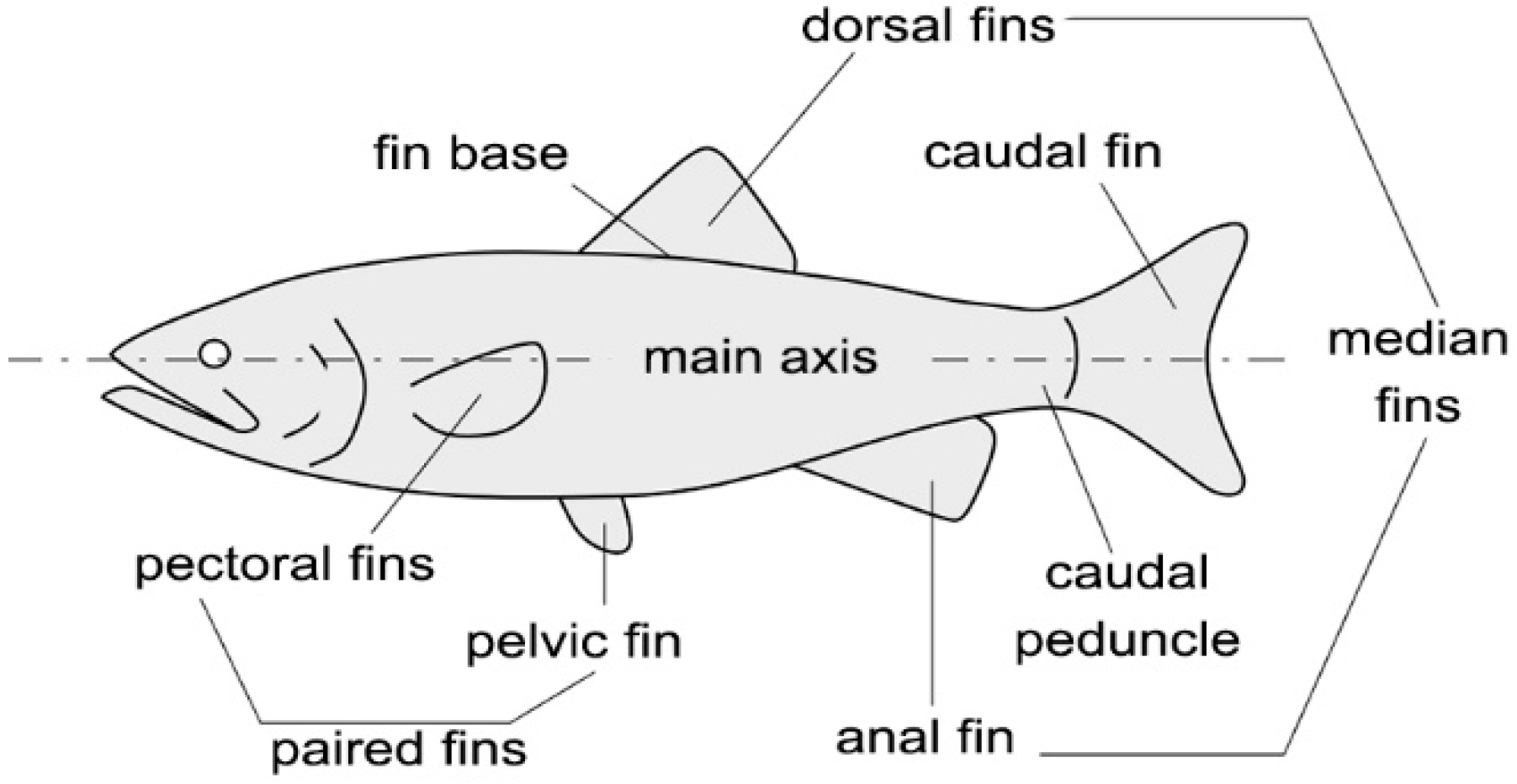
Figure 2.
Pectoral fin kinematics during power strokes (a) and recovery strokes (b) in drag-based labriform locomotion; pectoral fin kinematics in lift-based labriform locomotion (c).
Figure 2.
Pectoral fin kinematics during power strokes (a) and recovery strokes (b) in drag-based labriform locomotion; pectoral fin kinematics in lift-based labriform locomotion (c).

Figure 3.
Geometry of power and recovery strokes: the fin was drawn thin during the power stroke and flat during the recovery stroke to show its perpendicular and parallel orientation with respect to the horizontal plane (a); blade-element kinematics [6] (b).
Figure 3.
Geometry of power and recovery strokes: the fin was drawn thin during the power stroke and flat during the recovery stroke to show its perpendicular and parallel orientation with respect to the horizontal plane (a); blade-element kinematics [6] (b).
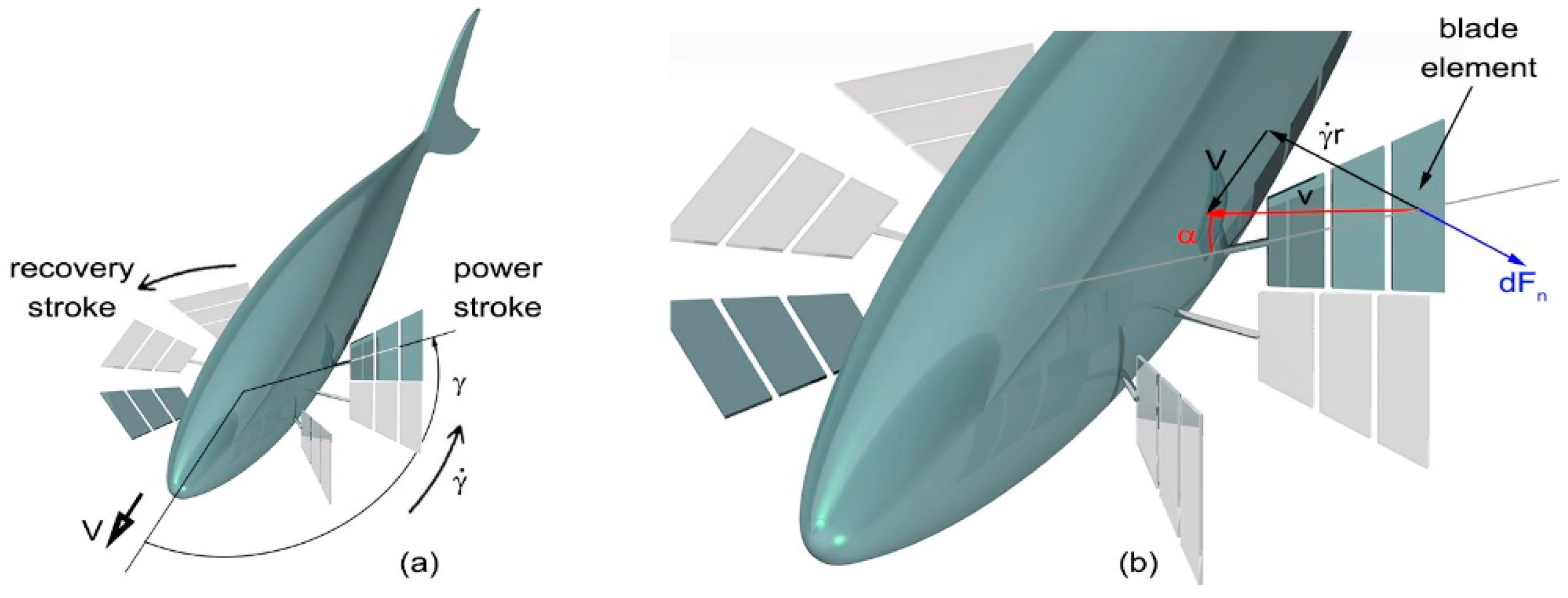
Figure 4.
Fin beat-cycle: power stroke: the fins are kept perpendicular to the horizontal plane as they rotate counterclockwise about the fish yaw axis at high speed (a); feathering recovery stroke: the fins turn around their pitch axis, flattening on the horizontal plane, as they slowly rotate clockwise about the yaw axis (b); main recovery stroke: the fins are kept parallel to the horizontal plane as they continue to rotate clockwise about the yaw axis (c); unfeathering recovery stroke: the fins turn around their yaw axis until they are perpendicular to the horizontal plane, as they complete the rotation around the yaw axis, thus returning in the initial position and configuration (d).
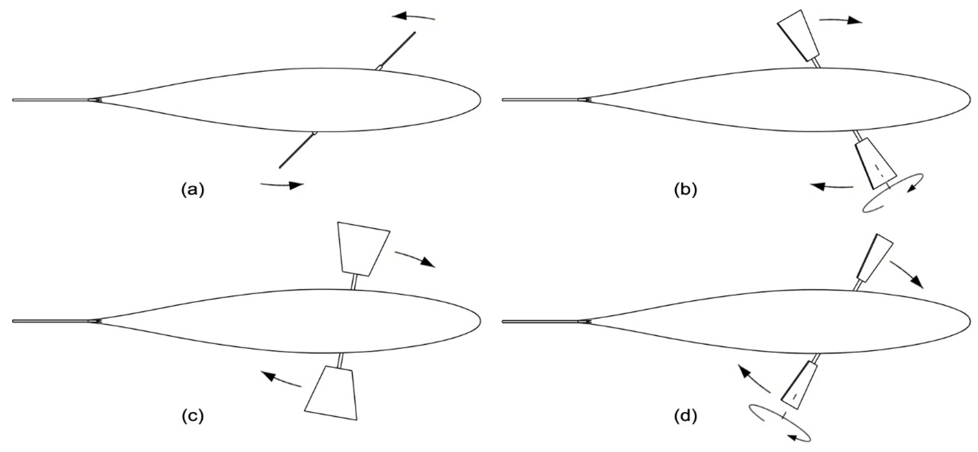
Figure 5.
Sub-system A (a); Sub-system B (b).

Figure 6.
Transmission mechanism and pectoral fin complete assembly: frame (orange), rotary motor and input shaft (grey), sub-system A (dark blue), sub-system B (red), shaft C and Double Cardan joints (cyan), fin shaft D (pearl); front view (a), back view (b).
Figure 6.
Transmission mechanism and pectoral fin complete assembly: frame (orange), rotary motor and input shaft (grey), sub-system A (dark blue), sub-system B (red), shaft C and Double Cardan joints (cyan), fin shaft D (pearl); front view (a), back view (b).
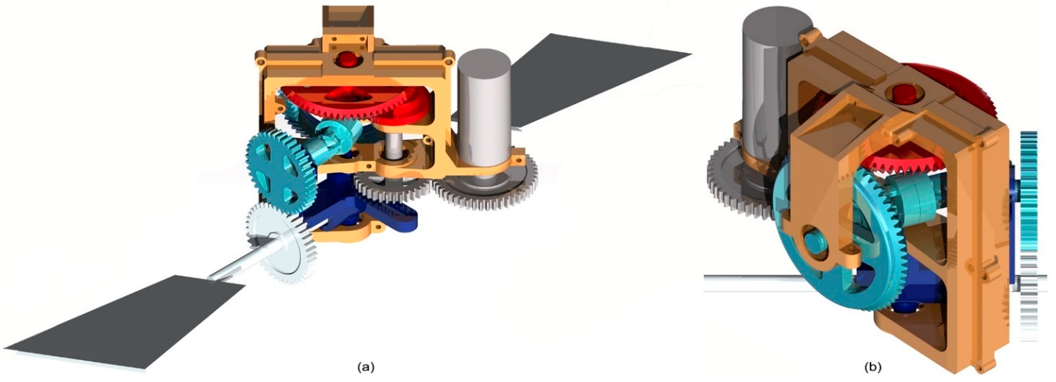
Figure 7.
Double Cardan joint assembly.

Figure 8.
Oscillating glyph at the beginning of a power stroke.

Figure 9.
Fin angular position and orientation in a fin beat-cycle.
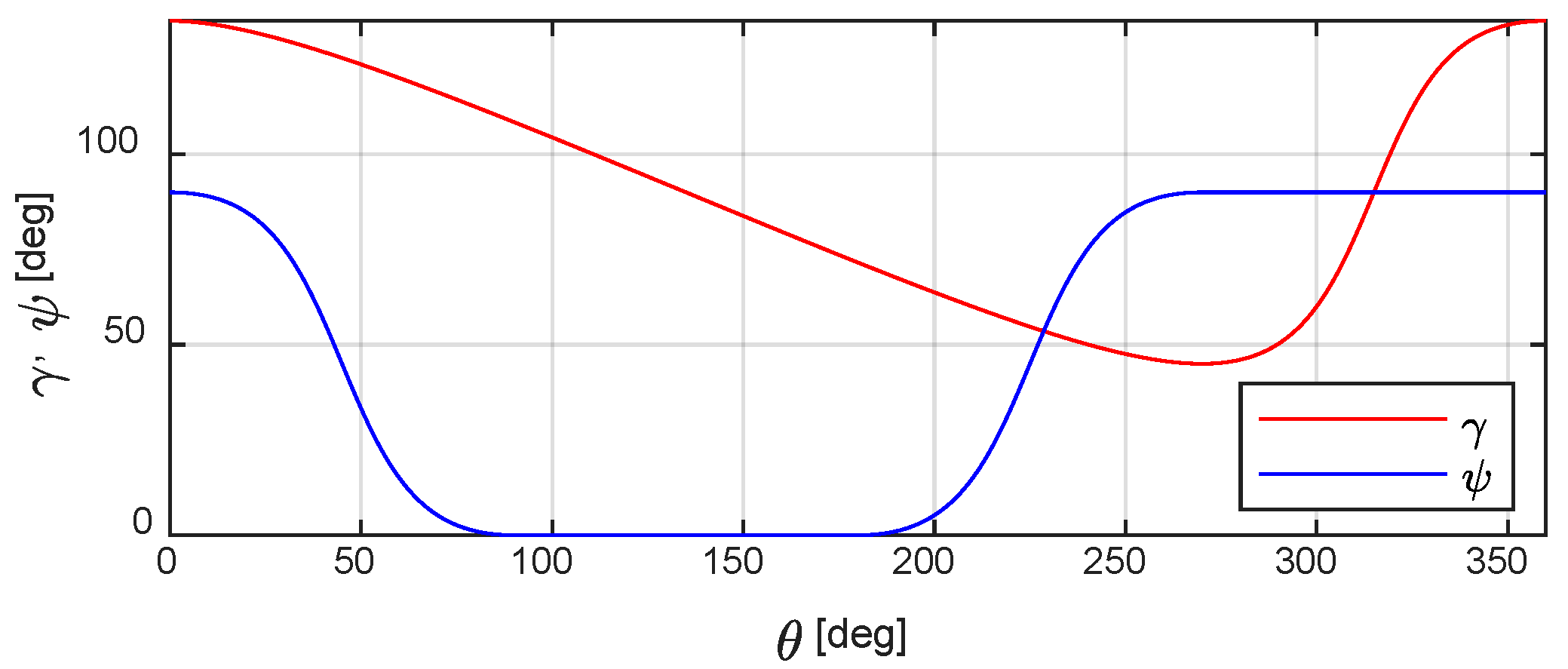
Figure 10.
Attack angle α during a power stroke: right fin (a) and left fin (b); the values were computed when the swimming velocity V was 0.125 BL/s (red), 0.25 BL/s (blue), and 0.5 BL/s (green). The markers on the curves refer to the innermost (circle), median (plus sign), and outermost (asterisk) blade-element.
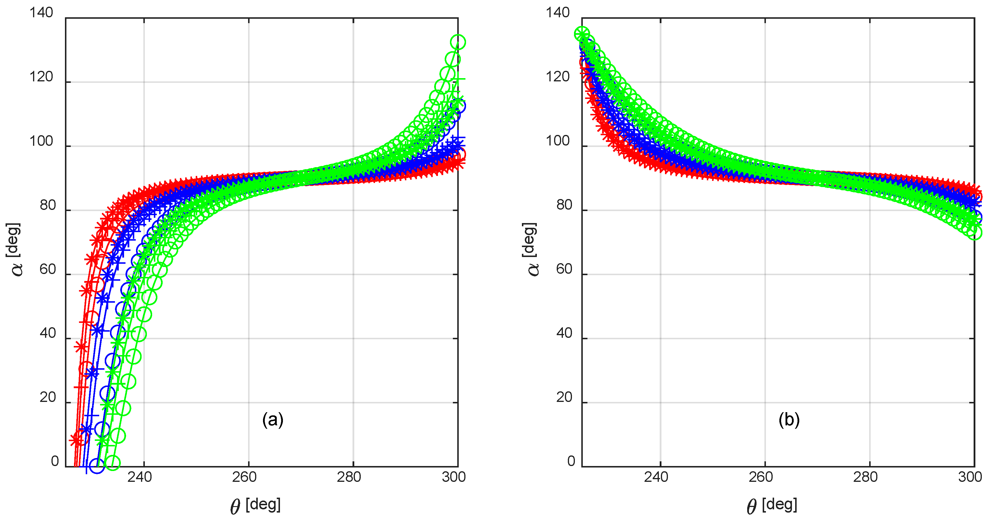
Figure 11.
Cylindrical body subject to the hydrodynamic loads (red) and to the propulsive/maneuvering forces generated by the caudal and pectoral fins (blue) (a); robotic fish subject to the hydrodynamic and propulsive loads applied to the tail sections and to the rigid forebody (b).
Figure 11.
Cylindrical body subject to the hydrodynamic loads (red) and to the propulsive/maneuvering forces generated by the caudal and pectoral fins (blue) (a); robotic fish subject to the hydrodynamic and propulsive loads applied to the tail sections and to the rigid forebody (b).
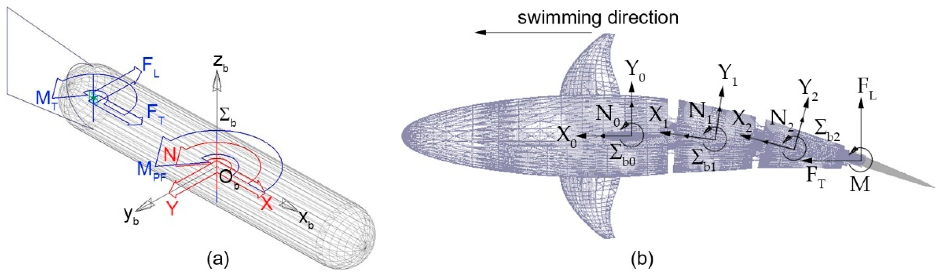
Figure 12.
Multibody model of the underwater robot.
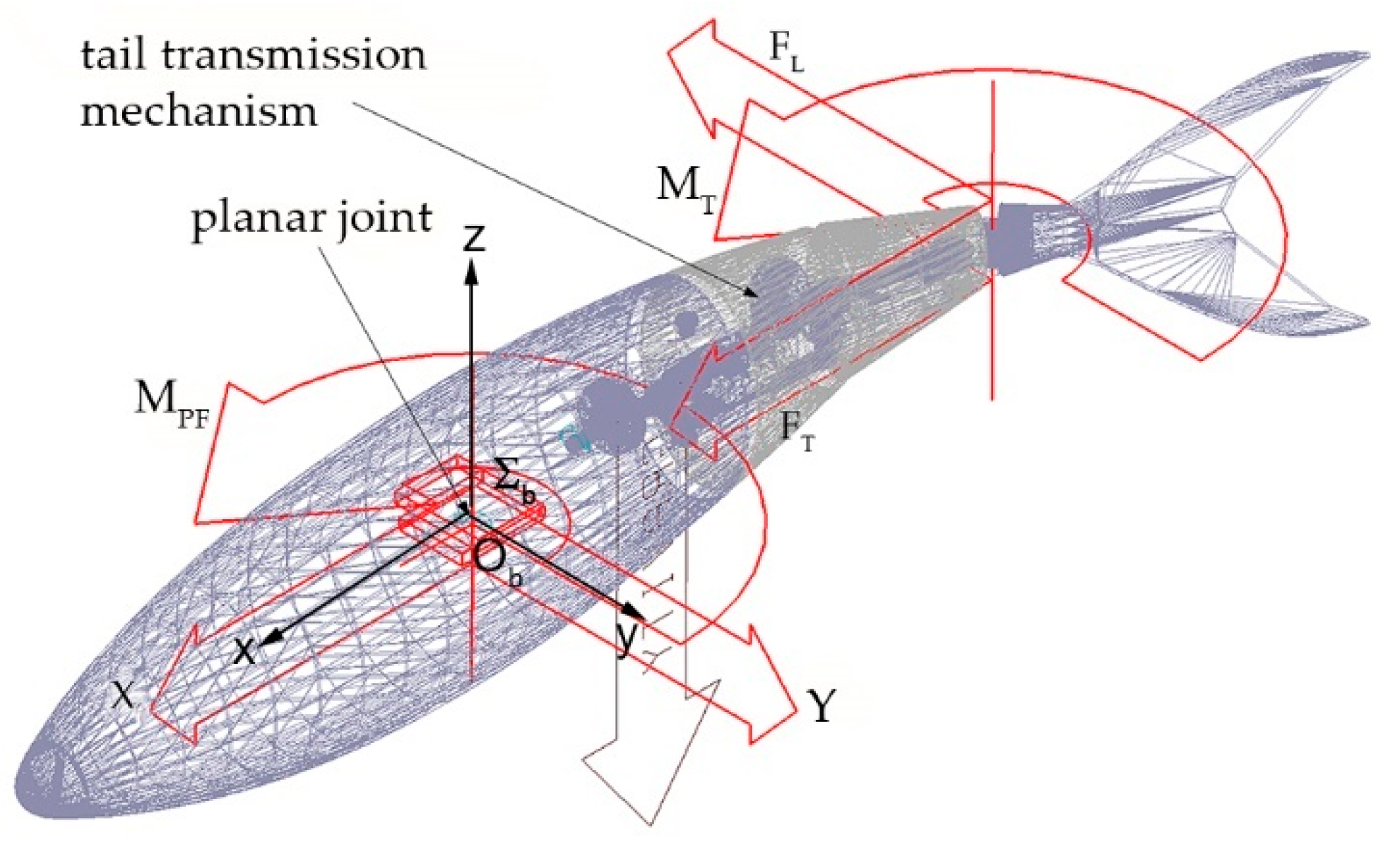
Figure 13.
Physical prototype of the transmission system manufactured by SLA.


Table 1.
Fin kinematics according to the phases of Figure 4.
Table 1.
Fin kinematics according to the phases of Figure 4.
| - | Power Stroke | Recovery Stroke | ||
|---|---|---|---|---|
| Time | Time 1 | Time 2 | Time 3 | Time 4 |
| Yaw rotation | Driven—fast | Driven—slow | Driven—slow | Driven—slow |
| Yaw angle γ 1 | 45° -> 135° | 135° -> 108.5° | 108.5° -> 71.5° | 71.5° -> 45° |
| Pitch rotation | Blocked | Driven | Blocked | Driven |
| Pitch angle φ | Trimmed at 90° | 90° -> 0° | Trimmed at 0° | 0° -> 90° |
1 The computation of the provided values is shown in Section 3.1.
Table 2.
Added mass and damping coefficient for a cylinder with radius R, length L, and mass m [22] (Reprinted from Ref. [5]).
| 0.5 | [0.8–1.2] |
Table 3.
Turnabout radius [BL] predicted by the multibody simulations as a function of the fish swimming speed and motor frequency.
Table 3.
Turnabout radius [BL] predicted by the multibody simulations as a function of the fish swimming speed and motor frequency.
| Motor Frequency | Swimming Speed | |||
|---|---|---|---|---|
| 0.125 BL/s | 0.25 BL/s | 0.50 BL/s | 1 BL/s | |
| 0.5 Hz | 3.16 | 7.17 | 12.25 | 14.93 |
| 1 Hz | 1.46 | 3.15 | 7.15 | 12.17 |
| 1.5 Hz | 0.98 | 1.97 | 4.44 | 9.35 |
| 2 Hz | 0.75 | 1.45 | 3.13 | 7.09 |
| 3 Hz | 0.53 | 0.96 | 1.94 | 4.41 |
Publisher’s Note: MDPI stays neutral with regard to jurisdictional claims in published maps and institutional affiliations. |
© 2022 by the authors. Licensee MDPI, Basel, Switzerland. This article is an open access article distributed under the terms and conditions of the Creative Commons Attribution (CC BY) license (https://creativecommons.org/licenses/by/4.0/).
Share and Cite
MDPI and ACS Style
Costa, D.; Scoccia, C.; Palpacelli, M.; Callegari, M.; Scaradozzi, D. Design of a Labriform-Steering Underwater Robot Using a Multiphysics Simulation Environment. Robotics 2022, 11, 11. https://doi.org/10.3390/robotics11010011
AMA Style
Costa D, Scoccia C, Palpacelli M, Callegari M, Scaradozzi D. Design of a Labriform-Steering Underwater Robot Using a Multiphysics Simulation Environment. Robotics. 2022; 11(1):11. https://doi.org/10.3390/robotics11010011
Chicago/Turabian StyleCosta, Daniele, Cecilia Scoccia, Matteo Palpacelli, Massimo Callegari, and David Scaradozzi. 2022. "Design of a Labriform-Steering Underwater Robot Using a Multiphysics Simulation Environment" Robotics 11, no. 1: 11. https://doi.org/10.3390/robotics11010011
Note that from the first issue of 2016, this journal uses article numbers instead of page numbers. See further details here.