Abstract
We propose a method to achieve autonomous gait transition according to speed for a quadruped robot pacing at medium speeds. We verified its effectiveness through experiments with the simulation model and the robot we developed. In our proposed method, a central pattern generator (CPG) is applied to each leg. Each leg is controlled by a PD controller based on output from the CPG. The four CPGs are coupled, and a hard-wired CPG network generates a pace pattern by default. In addition, we feed the body tilt back to the CPGs in order to adapt to the body oscillation that changes according to the speed. As a result, our model and robot achieve stable changes in speed while autonomously generating a walk at low speeds and a rotary gallop at high speeds, despite the fact that the walk and rotary gallop are not preprogramed. The body tilt angle feedback is the only factor involved in the autonomous generation of gaits, so it can be easily used for various quadruped robots. Therefore, it is expected that the proposed method will be an effective control method for quadruped robots.
1. Introduction
Quadruped mammals choose a gait according to their speed [1]. Most quadruped mammals choose a walk at low speeds, while at medium and high speeds the chosen gait varies depending on species. A chosen gait may be a trot or pace at medium speeds and a transverse gallop or rotary gallop at high speeds. Specifically, cats change their gait from walk to trot to transverse gallop according to speed [1], whereas greyhounds change their gait from walk to pace to rotary gallop according to speed [2,3]. Furthermore, the locomotion of quadruped robots and quadruped simulation models has been achieved by using mammals’ gaits as a basis [4,5,6,7,8,9,10,11,12,13,14,15,16,17,18,19].
It has been reported that quadruped mammals such as cats can change their gait even without a brain, even though the principle of gait transition is not clear. Grillner [20] and Golubitsky et al. [21] reported that gait transition occurs as a result of each leg swinging reflexively with a central pattern generator (CPG), which is a neural circuit existing in the spinal cord. Based on this, there are quadruped simulation models [22,23,24,25,26] and quadruped robots [23,24,27,28,29,30] that autonomously produce gaits not defined by CPG. These autonomously modify the phase differences between the four legs by using external factors such as sensory feedback and, as a result, some gaits emerge. However, the range of speeds of these studies is limited.
The first study that achieved autonomous gait transition from low to high speed was our simulation study [31]. We achieved autonomous gait transition from walk to trot to transverse gallop using a quadruped simulation model. The basic gait is set to trot by the CPG network with mutual inhibitory coupling between the CPGs of each leg. Despite this setting, the quadruped simulation model generated the walk at low speeds and the transverse gallop at high speeds, even though it was not defined in the program by feeding the body tilt back to the CPG. In this paper, this feedback is called vestibular modulation. In addition, the quadruped robot “Spinalbot” achieved gait transition from walk to trot to transverse gallop similar to the simulation result by applying a similar method [32]. Moreover, based on the same concept, a quadruped simulation model feeding the leg load back to the CPG achieved gait transition [33]. Owaki et al. achieved gait transition from walk to trot to transverse gallop using a quadruped robot with CPG and feeding the leg load back to the CPG [34].
As mentioned above, mainly only quadruped robots that achieve gait transition with the basic gait set to trot have been developed. Although not as common, quadruped robots with the basic gait set to pace have also been developed [35,36,37,38]. However, it has been reported that the pace is an effective gait [2] and that trot and pace at medium speeds are selected according to the differences in body structure. In particular, pace is an effective gait on long-legged quadruped robots because interference between fore and hind legs rarely occurs as the ipsilateral legs swing simultaneously. Therefore, the purpose of this study is to propose a gait transition method for a quadruped robot pacing at medium speeds. We applied the gait transition method with the basic gait set to trot to Spinalbot with pace as the basic gait. Specifically, each leg of Spinalbot was equipped with a CPG, and the CPG network was set to a pace pattern through mutual excitatory coupling between the CPGs of the fore and hind legs and mutual inhibitory coupling between the CPGs of the left and right legs. As a result, Spinalbot locomoted at a pace without vestibular modulation. However, running with a flight phase at a pace was unstable. One of the issues is that body oscillation and leg oscillation are not coordinated. Therefore, we applied vestibular modulation to Spinalbot to coordinate the two oscillations. As a result, the gait autonomously transitioned from walk to pace to rotary gallop according to the speed, and it was found from the results that stable locomotion is possible even at high speeds.
It has been reported that rotary gallop, as appearing in this paper, and transverse gallop, as appearing in our previous studies [31,32], have different roles as follows. The advantages of transverse gallop are high stability and reduced energy consumption. The disadvantage of transverse gallop is that the leading legs are the same between the fore legs and the hind legs, therefore the leading legs must be changed when turning, the start of turning is delayed, and there is a lack of agility. By contrast, the advantage of rotary gallop is that the leading legs are different between the fore legs and the hind legs, respectively, so it is unnecessary to change the leading legs, regardless of the turning direction, and there is high maneuverability. Therefore, it is assumed that rotary gallop is preferred for quadruped robots that are required to turn. In addition, the maximum running speed by rotary gallop tends to increase; hence, it is assumed that rotary gallop is preferred for quadruped robots that are required to locomote at high speed. Although rotary gallop has many advantages, only a few quadruped robots using rotary gallop have been developed, such as Scout II, which was developed by Smith et al. [39].
As mentioned above, it is expected that our motion generation method would be effective not only as a method for enabling a gait transition from walk to trot to transverse gallop but also as a simple general-purpose method enabling gait transition from walk to pace to rotary gallop similar to a greyhound for a quadruped robot. As these gait transitions can be achieved by applying an inexpensive inclination sensor, the method is considered to be applicable to various quadruped robots.
The structures of both the simulation model and robot are presented in Section 2. Section 3 describes the control method, including the configuration of the CPG and sensory feedback. The achievement of gait transition by the simulation model is shown in Section 4.2 and the experimental results of the robot are shown in Section 4.3. The principle by which walk and rotary gallop appear is explained in Section 5. Finally, in Section 6, we present our conclusions and future work.
2. Spinalbot Quadruped Robot and Simulated Model
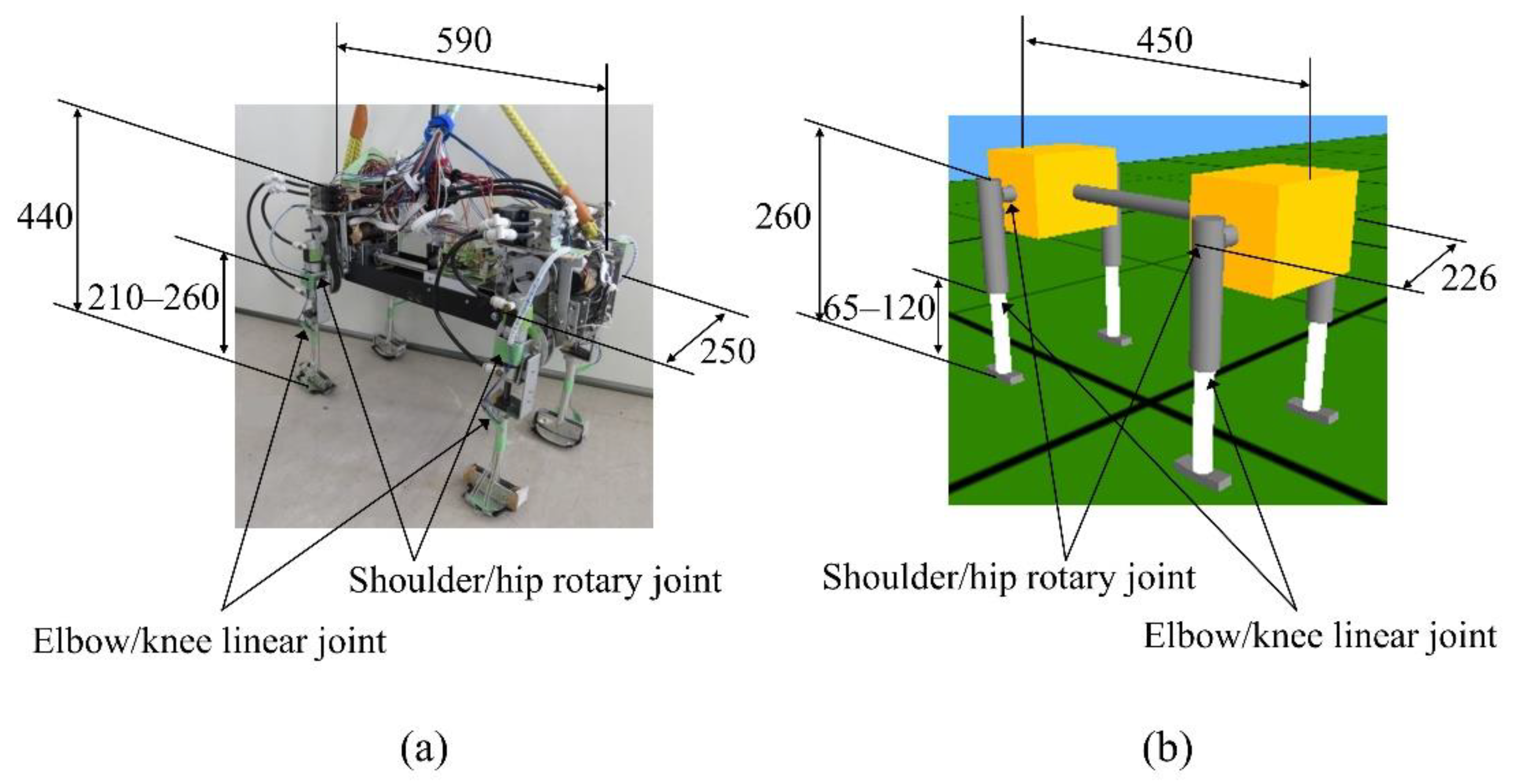
Figure 1 shows the “Spinalbot” quadruped robot and model that we developed. Spinalbot is a simple structure with a rigid torso. All legs have the same structure and two joints: a rotary joint around the pitch axis (shoulder/hip) and a linear joint (elbow/knee). The model weighs 7.8 kg, the body weighs 7.0 kg, and each leg weighs 0.2 kg. The robot weighs 11.8 kg, the body weighs 9.7 kg, and each leg weighs 0.51 kg. The rotation joints are driven by DC motors (150 W, RE40, Maxon Co., Sachseln, Switzerland) with a reduction ratio of 19.3:1. The linear joints are driven by pneumatic actuators (CG3BN25-50, SMC Co., Tokyo, Japan) and used as a variable elastic mechanism. The amount of air supplied from the air compressor (0.4 MPa at walking, 0.6 MPa at running) in the cylinder of the pneumatic actuator is modified by the solenoid valve (VZ212-5MZ-M5, SMC Co., Tokyo, Japan), therefore the air pressure in the cylinder is adjusted to be low at low speeds and high at high speeds. Each leg is designed based on a spring-loaded inverted pendulum (SLIP) model [40]. The SLIP model is a simple model of the body of an animal during locomotion.
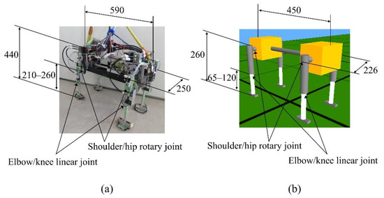
Figure 1.
Robot (a) and simulated (b) model of Spinalbot.
Spinalbot is equipped with an encoder combined with a DC motor for acquiring the rotary joint angle. It is possible to measure the body tilt by using an inclination sensor combined with a gyro sensor (ENC-03R C/D, Murata Co., Kyoto, Japan) and an accelerometer (SCA61T-FA1H1G, VTI Technologies Co., Vantaa, Finland). The pressure sensors (FlexiForce A201-25, Nitta Co., Osaka, Japan) are equipped on the feet and are used as a binary sensor for acquiring the touch information.
Spinalbot is controlled by a robot controller network connecting with a sampling time of 2 ms and connected power supplies, motor drivers, and the air compressor installed outside. Experiments are carried out with both the simulation and the robot constrained in the sagittal plane. The pitch vibration of the torso when running at a gallop is large, while the roll vibration is small. Therefore, it is considered that the experiment in the sagittal plane has little effect on the emergence of gait. Robot experiments are performed on a treadmill with the speed controlled by the experimenter.
3. Motion Generation Control
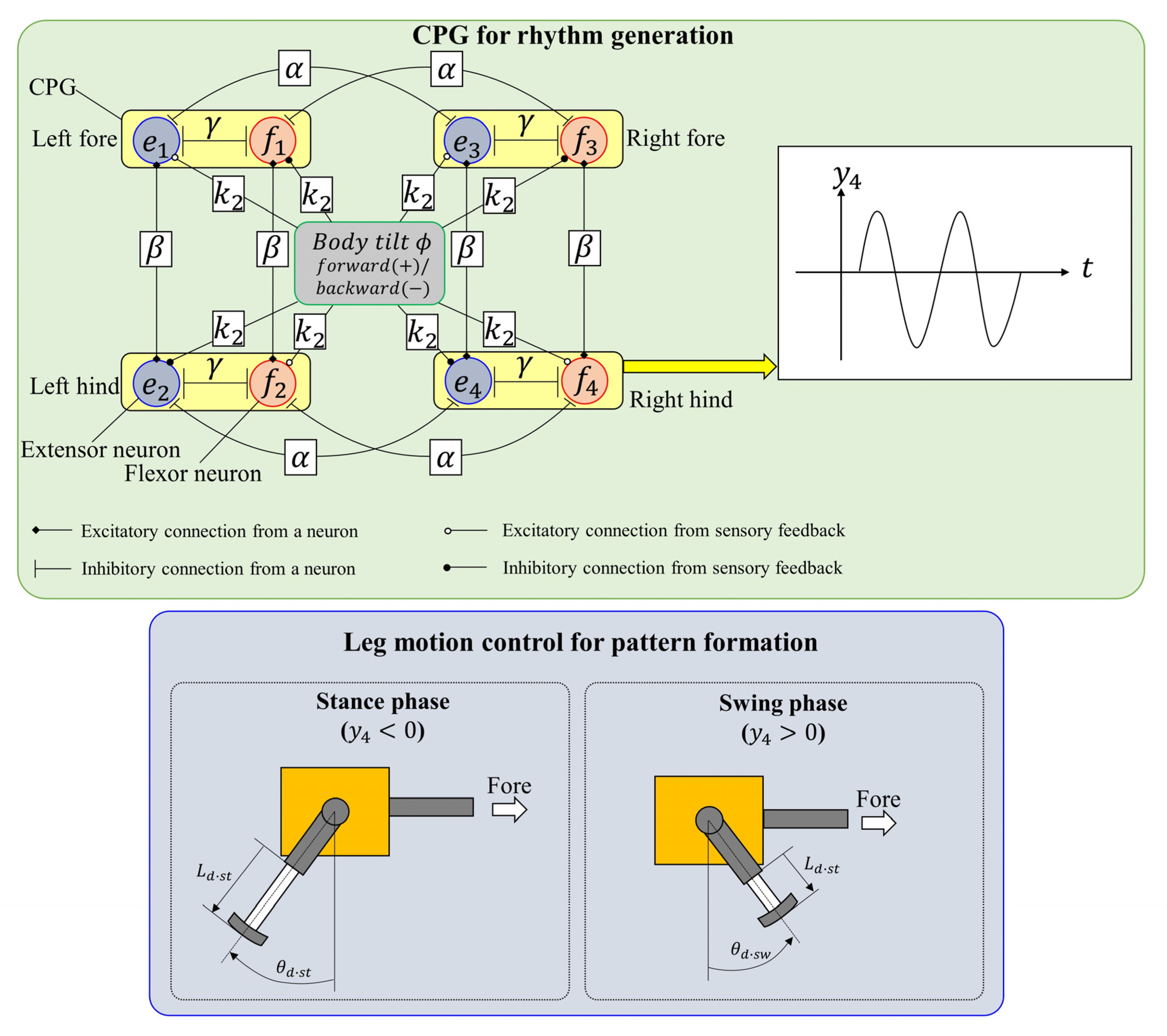
The CPG neural circuit of quadruped mammals generates the locomotion rhythm according to the locomotion state. As shown in Figure 2, Spinalbot achieves walking and running by using a control method combining a CPG generating a rhythm pattern and a PD controller. The method is the same as in the previous studies [31,32] except for the coupling between the CPGs.
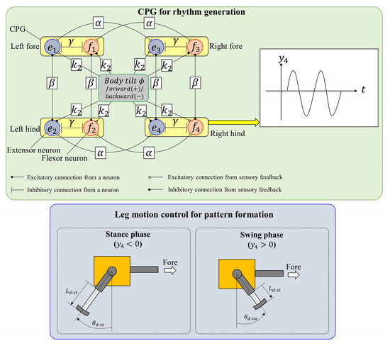
Figure 2.
Neural configuration.
3.1. Rhythm Generation
3.1.1. CPG Model and CPG Network
The CPG models proposed by Matsuoka [41] generate the rhythm of each leg. The CPG model is represented by the following equations:
The subscripts e and f denote the extensor and flexor, respectively, is the number of the leg (1: left fore; 2: left hind; 3: right fore; and 4: right hind). The variables and are the fatigue state and inner state of each neuron of each leg, respectively; is the output of the neuron; is the output of the CPG of each leg; s is a driving input; b is a fatigue coefficient; is the connection strength between the extensor neuron and the flexor neuron; and are the connection strengths between the neurons of each leg; and and are time constants.
The CPG output of each leg is represented by:
In order to synchronize the CPG oscillations of each leg and the leg oscillation based on the biological findings [42], the rotary angles are fed back to the CPGs of each leg as shown below:
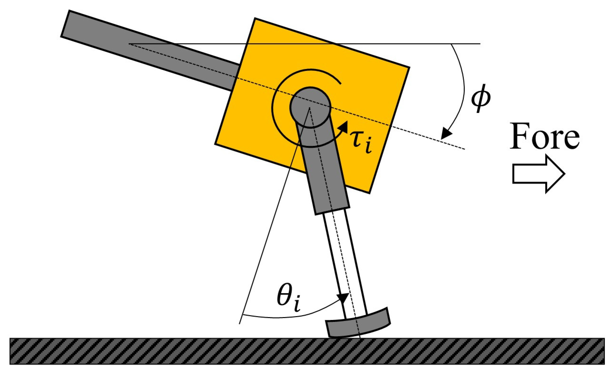
where is gain, is the present angle of the rotary joint of each leg, and is the origin angle of each leg. The rotational direction of the rotary joint is shown in Figure 3.

Figure 3.
Diagram of leg motion and body tilt.
As shown in Figure 2, the CPG network is constructed by coupling the CPGs of each leg with coupling coefficients and . As a result, the CPG network generates a pace pattern that swings the ipsilateral legs simultaneously so as not to couple the diagonal legs [43]. As the values of and are not changed, the coupling state is unchanged and the basic gait is a pace.
3.1.2. Vestibular Modulation
Based on the finding by Roberts [44], the body tilt around the pitch axis is fed back to the CPGs for vestibular modulation, as shown below:
where is gain and is the present body tilt angle around pitch axis. Therefore, the stance phases of the leg on the side toward which the body is inclined are extended and the swing phases of the leg on the side toward which the body is not inclined are extended.
3.2. Leg Motion Generation
Each leg is controlled on the basis of the CPG outputs. As shown in the lower side of Figure 2, the phase (stance phase or swing phase) of each leg is determined on the basis of the CPG outputs. When the flexor neuron of the CPG is activated (), the phase is the swing phase. By contrast, when the extensor neuron of the CPG is activated (), the phase is the stance phase. The rotary joint (shoulder/hip) of each leg is controlled to the desired angle according to the phase by the PD controller with:
where is the torque output; and are the proportional and derivative gains in the swing and stance phases, respectively; is the desired angle of the rotary joint; and is the present angle of the rotary joint. Specifically, the rotary joint is swung forward with as the desired angle during the swing phase and backward with as the desired angle during the stance phase.
Regarding the elbow/knee joint of each leg, the linear joint of the simulated model is PD-controlled with:
where is the force output; and are the proportional and derivative gains in the swing and stance phases, respectively; is the desired length of the linear joint; and is the present length of the linear joint. Specifically, each leg is shortened to as the desired length during the swing phase and extended to as the desired length during the stance phase.
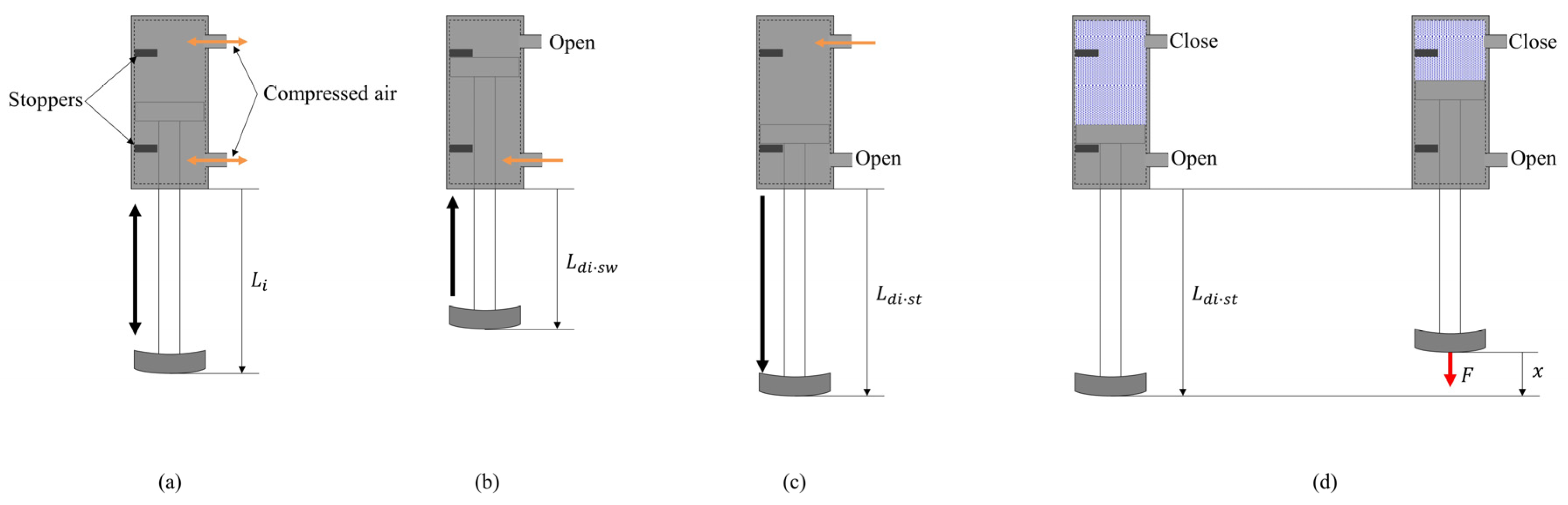
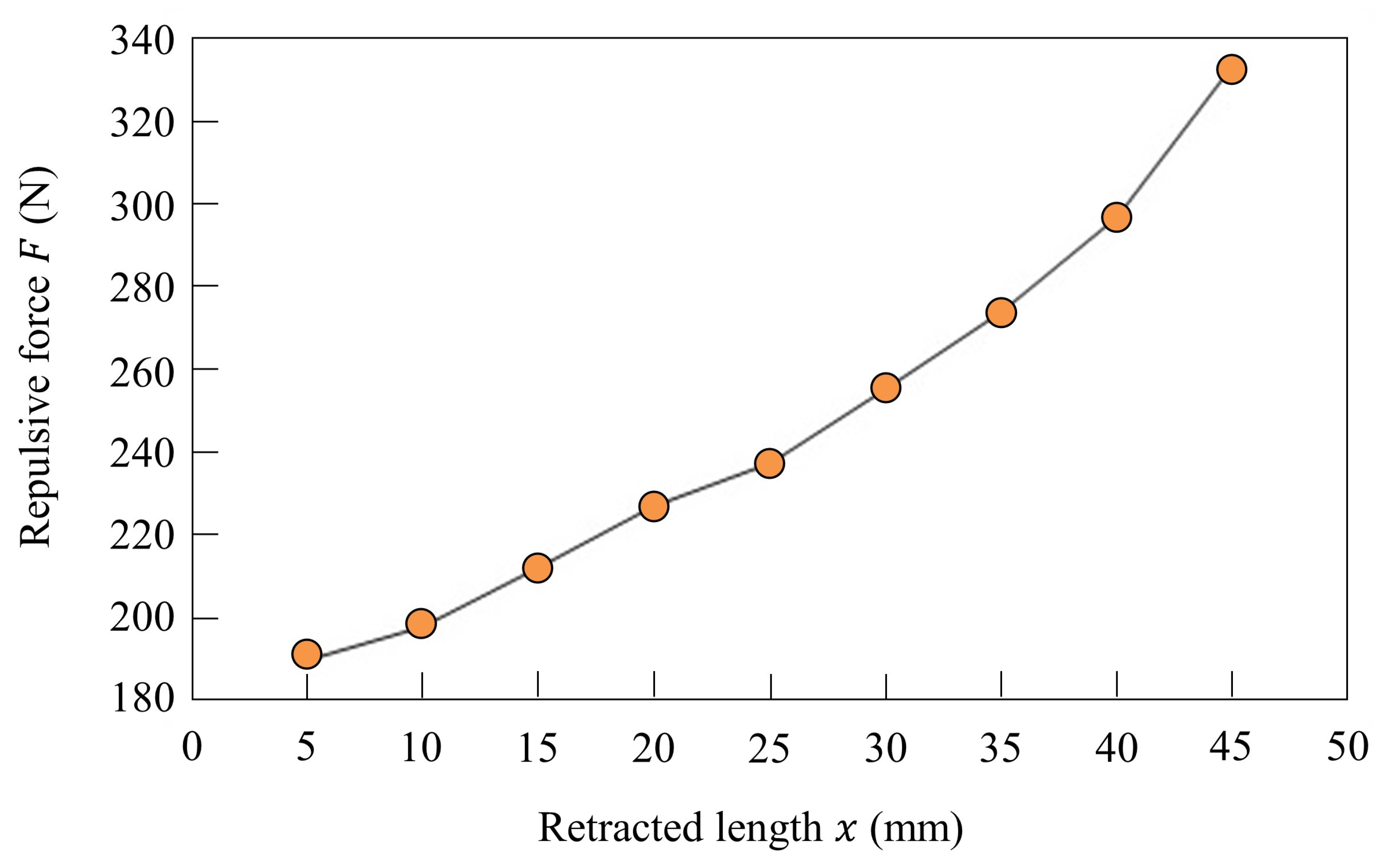
The length and stiffness of the linear joint of the robot are modified by controlling inflow and discharge of air using a solenoid valve. Figure 4a shows the structure of the pneumatic actuator. There are two inflow/outflow ports on the top and on the bottom, and the pneumatic actuator is driven by putting compressed air in the chambers. As shown in Figure 4b, the chamber at the top of the cylinder is opened and the compressed air is put in the chamber at the bottom of the cylinder, and the leg is retracted to mm in the swing phase. As shown in Figure 4c, the compressed air is put in the chamber at the top of the cylinder for T seconds and the chamber at the bottom of the cylinder is opened. Despite the value of T, the leg is extended to mm. After T seconds, the chamber at the top of the cylinder is closed, as shown in Figure 4d, and the air quantity in the cylinder is kept constant. Therefore, the leg in the stance phase functions as an air spring. The elastic force of this air spring is modified by the value of T. To change the stiffness of each leg, the elastic force is modified by increasing T according to the speed. Figure 5 shows the elastic forces of the leg when T = 54 ms, which was used when Spinalbot galloped at a speed of 1.2 m/s. Figure 4c shows this experimental state. Figure 5 indicates that sufficient elastic force can be obtained for running.
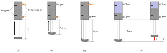
Figure 4.
Diagram of the linear join: (a) a general diagram, (b) a state in the swing phase, (c) a state in the stance phase, and (d) a setting to measure the stiffness for Figure 5.
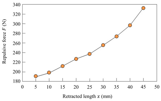
Figure 5.
Stiffness of the linear joint in the stance phase when ms.
4. Results
The Spinalbot quadruped robot achieved autonomous gait transition with the proposed method. In addition, the simulation model under the ideal environment where the joint frictions of each leg are the same and rolling does not occur achieved the same gait transition, and the reliability of the experimental results was demonstrated. Video records are available in the Supplementary Materials (Video S1).
4.1. Speed Parameter
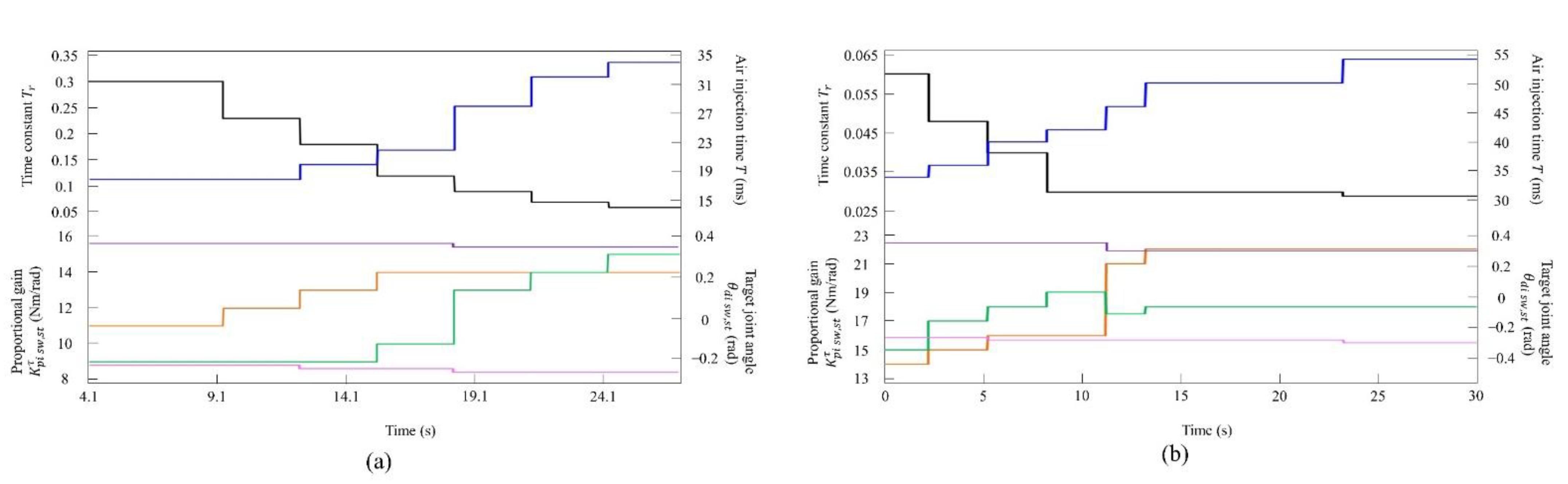
The values of each control parameter, as shown in Table 1, were the same in all legs and were unchanged during the experiment. The CPG network parameters were experimentally determined. Although it is possible to use an optimization algorithm [45], the CPG parameters had high robustness, as shown in Section 4.4, and it was possible to easily determine the parameters that achieved gait transition even by manual tuning. The values of and were set to generate a pace. The propulsive force was modified by changing the values of the parameters—the parameter for determining the leg cycle, ; the desired angle of the rotary joint, ; the proportional gain of the rotary joint, ; the parameter for determining the stiffness, ( in the simulation)—other than those parameters shown in Table 1, and the speed was changed. In this paper, these parameters were called “speed parameters”. As the speed parameters were also the same in all legs, in the experiment without vestibular modulation (Equation (10)), the phase differences between the four legs were not modified by changing the values of the speed parameters. The procedures for changing the values of the speed parameters in the simulation and in the experiment with Spinalbot are shown in Figure 6 and Figure 7, respectively. The speed parameters were modified for each of the low- to medium-speed experiments ((a) of Figure 6 and Figure 7) and the medium- to high-speed experiments ((b) of Figure 6 and Figure 7). The speed parameter contributes not only to speed change but also to posture stability. There were differences in mechanical features (e.g., size, weight, and viscous friction) between the simulation model and the robot. The sizes could not be matched due to mechanical constraints caused by the size of the devices and actuators. Moreover, in the simulation, it was difficult to model the viscous friction of the rotary joint and the pneumatic characteristics of the linear joint of the robot. For these reasons, the mechanical parameters differed between the simulation model and the robot. Therefore, there was a difference in the speed parameter. Furthermore, because it was modified according to the speed parameter, there was a difference in the CPG parameter. The reason each parameter changes stepwise is that the speed can be increased almost smoothly, even when changing the parameters step by step at an arbitrary time. The values of each parameter were experimentally determined so that stable walking and running were possible in each speed range.

Table 1.
Parameters.
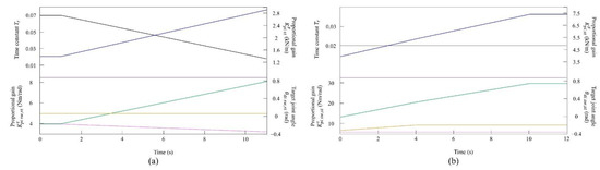
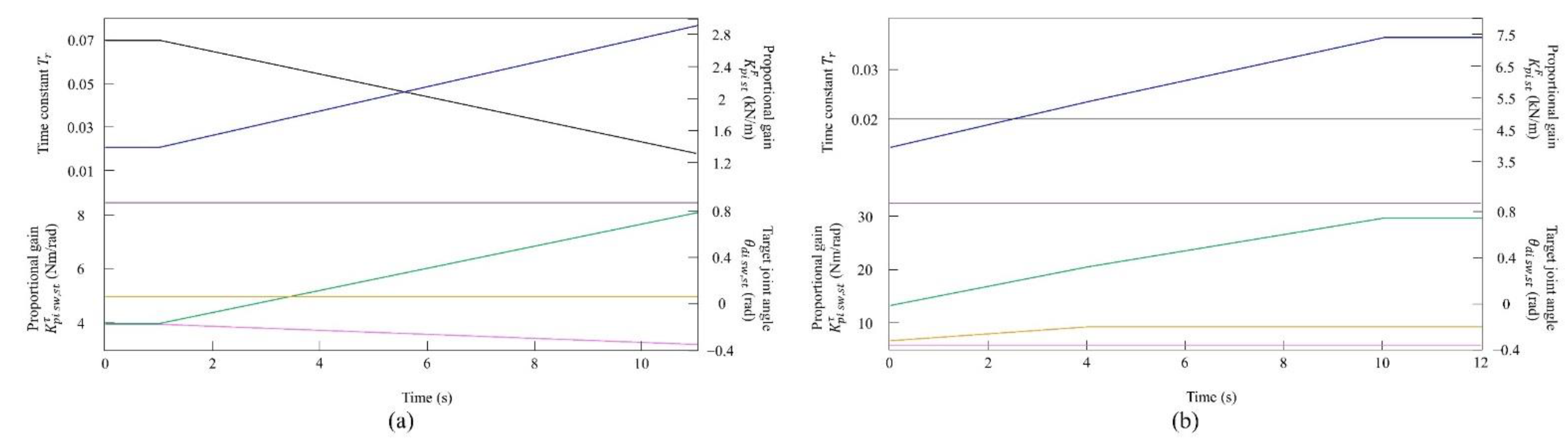
Figure 6.
Values of the speed parameters for the simulated model (a) at low to medium speeds and (b) at medium to high speeds. The parameters are colored as follows: : black; : blue; : orange; : green; : purple; and : magenta.
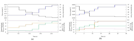
Figure 7.
Values of the speed parameters for the robot (a) at low to medium speeds and (b) at medium to high speeds. The parameters are colored as follows: : black; : blue; : orange; : green; : purple; and : magenta.
In general, although it is known that the change in the walking and running cycles is caused by the adjustment of the driving input to the CPGs ( in Equations (1) and (4)), in this paper, was modified to adjust the leg oscillation cycle because the influence of in Equations (1) and (4) on the cycle is larger than that of in the CPG model of Matsuoka [41].
The value of is divided into low to medium speed and medium to high speed, but gait transition is possible even with the same value. In this paper, as shown in Section 4.2 and Section 4.3, the value of was set separately so that the phase difference between the legs was the largest to clarify the differences between the emergent gaits. The effect of the value of on locomotion, including emergent gaits, is described in Section 4.4.
4.2. Simulated Results
We observed the emergence of different gaits by changing the speed. LF, LH, RF, and RH represent left foreleg, left hind leg, right foreleg, and right hind leg, respectively.
4.2.1. Gait Transition from Walking to Pacing with Vestibular Modulation in Simulation
In the walking experiment in the simulation, the same results as in the experiment with the robot were obtained. Table 1 shows the parameters at 0.8 m/s. By changing the speed parameters as shown in Figure 6a, we allowed the quadruped model to locomote at low to medium speeds. Regardless of the value of each parameter, the speed parameters were the same for the four legs, and the connection strength between CPGs (, ) was set so that no gait other than pace appeared when vestibular modulation was not applied () at all speeds. It was confirmed by experiments that no gait other than pacing appeared in walking without vestibular modulation, and that changes in the values of speed parameters had no effect on gait transition.
By contrast, only was changed and we allowed the quadruped model to locomote with vestibular modulation () from low to medium speeds, as shown in Figure 8. In this case, different gaits appeared at low speeds. The gait at medium speeds was a pace, but at low speeds walking emerged. As the speed increased, the gait shifted from walking to pacing. At low speeds (0.08 to 0.4 m/s of Figure 8), walking in which the leg moves in the order LF−RH−RF−LH, as shown in Figure 9a, emerged. At medium speeds (0.4 to 0.58 m/s of Figure 8), as shown in Figure 9b, the gait shifted to pacing in which the leg moves simultaneously with the pair of LF and LH and with the pair of RF and RH, and the pairs moved in reverse. As shown in Figure 9a,b, the body tilt angle during walking was larger than that during pacing. This phenomenon is an important factor in the emergence of walking and the transition to pacing.
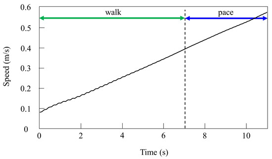
Figure 8.
Speeds during gait transition from walking to pacing in the simulation.
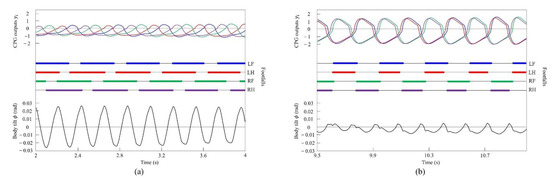
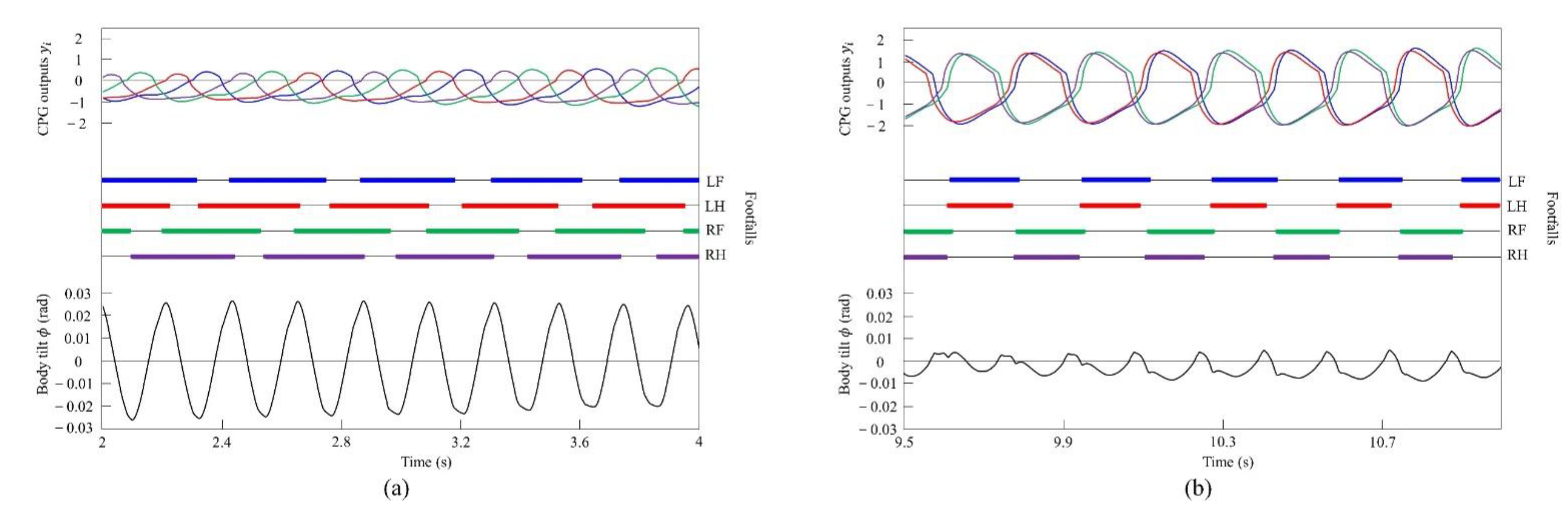
Figure 9.
Simulated results for walking and pacing at low and medium speeds, respectively: (a) a walk at 0.2 m/s and (b) a pace at 0.5 m/s. LF, LH, RF, and RH represent left foreleg, left hind leg, right foreleg, and right hind leg, respectively. CPG outputs are colored as follows: LF: blue; LH: red; RF: green; and RH: purple. The footfalls are indicated by thick line segments. The black wavy line represents body tilt (positive when facing down).
4.2.2. Gait Transition from Pacing to Galloping with Vestibular Modulation in Simulation
In the running experiment in the simulation, the same results as achieved in the experiment with the robot were obtained. By changing the speed parameters as shown in Figure 6b, we allowed the quadruped model to locomote at medium to high speeds. As in Section 4.2.1, it was confirmed by experiments that no gait other than pacing appeared in running without vestibular modulation. By contrast, when only was changed and we allowed the quadruped model to locomote with vestibular modulation from medium to high speeds, as shown Figure 10, galloping appeared at high speeds. This means that a gait transition from a pace at medium speeds to a rotary gallop at high speeds was achieved. At medium speeds (0.8 to 1.0 m/s of Figure 10), as shown in Figure 11a, the gait shifted to pacing in which the leg moved simultaneously with the pair of LF and LH and with the pair of RF and RH, respectively, and the pairs moved in reverse. At high speeds (1.0 to 1.65 m/s of Figure 10), the gait shifted to a rotary gallop in which the leg moved in the order LF−RF−RH−LH, as shown Figure 11b. As shown in Figure 11a,b, the body tilt angle during galloping was larger than that during pacing. As shown in Figure 11 and Figure 15, the same phenomenon as in the robot experiment appeared, indicating that the change in the vibration of the trunk according to the speed is the factor of gait emergence even in the ideal state of simulation.
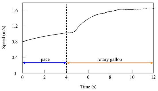
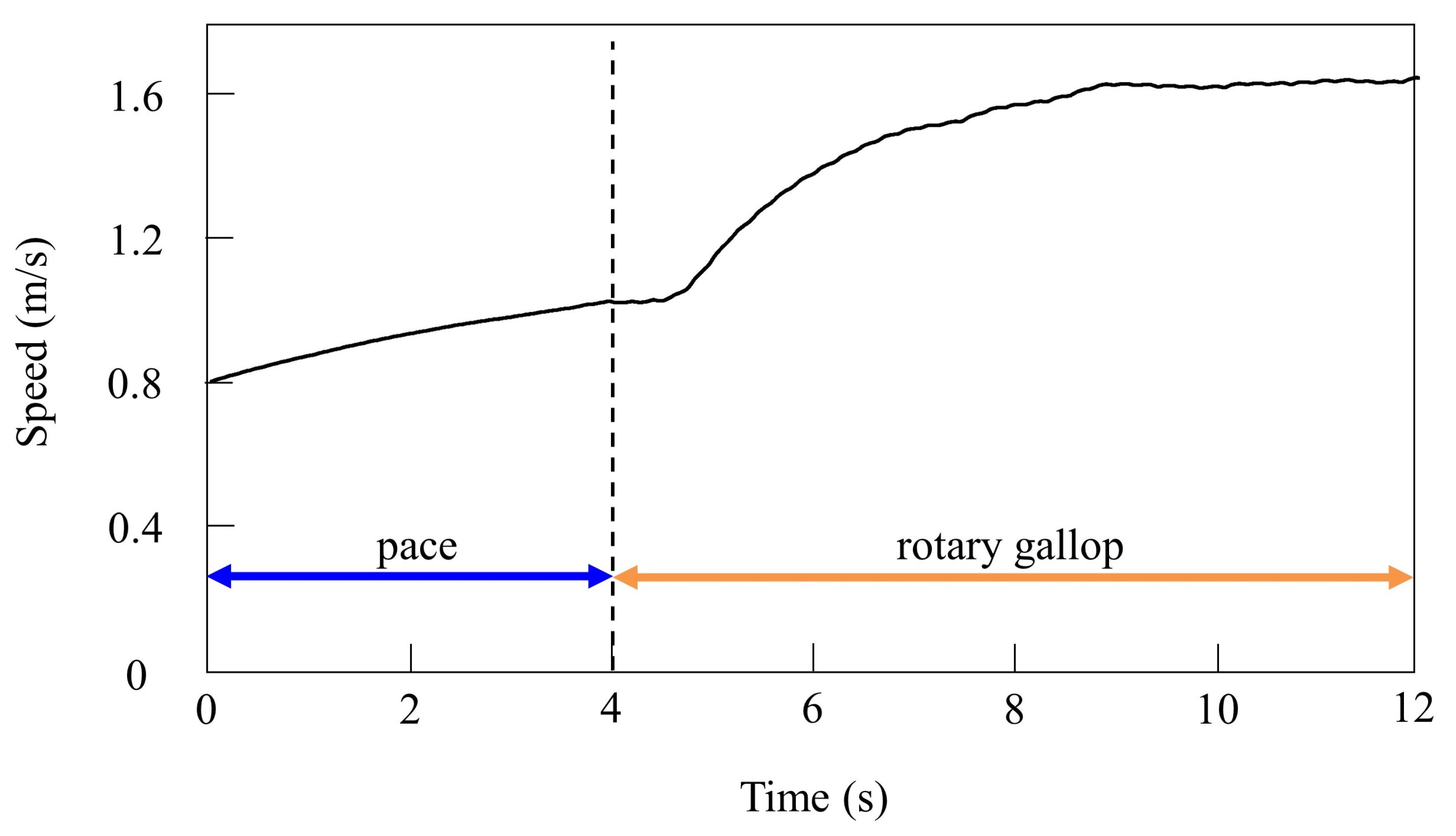
Figure 10.
Speeds during gait transition from pacing to galloping in the simulation.
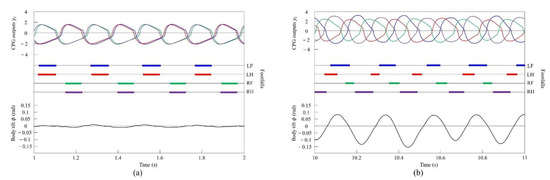
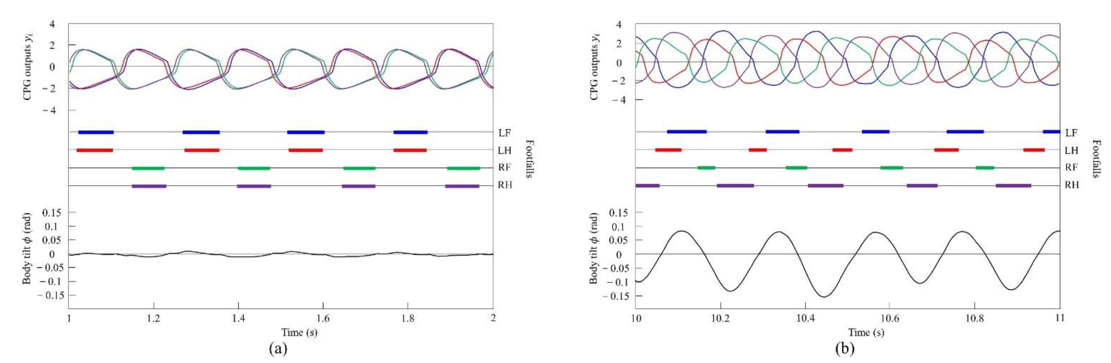
Figure 11.
Simulated results for pacing and galloping at medium and high speeds, respectively: (a) a pace at 0.9 m/s and (b) a rotary gallop at 1.6 m/s. LF, LH, RF, and RH represent left foreleg, left hind leg, right foreleg, and right hind leg, respectively. CPG outputs are colored as follows: LF: blue; LH: red; RF: green; and RH: purple. The footfalls are indicated by thick line segments. The black wavy line represents body tilt (positive when facing down).
4.3. Experimental Results
4.3.1. Gait Transition from Walking to Pacing with Vestibular Modulation
By changing the speed parameters as shown in Figure 7a, we allowed Spinalbot to locomote at low to medium speeds. It was possible to increase the speed even when using values other than those shown in Figure 7a. Regardless of the value of each parameter, the speed parameters were the same for the four legs, and the connection strength between CPGs (, ) was set so that no gait other than pace appeared when vestibular modulation was not applied () at all speeds. For this reason, it was confirmed through experimentation that the change in the speed parameter does not affect the gait transition without vestibular modulation.
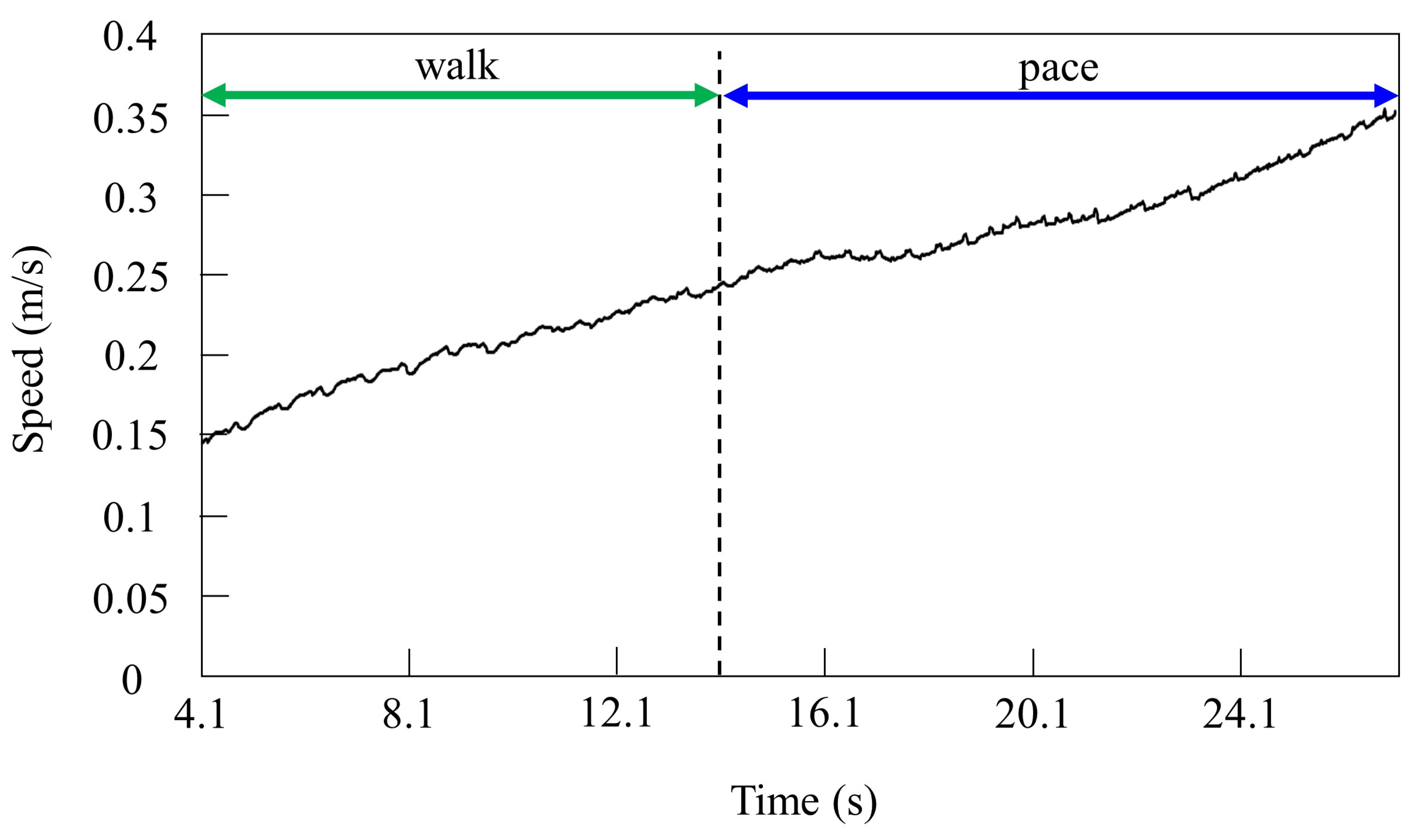
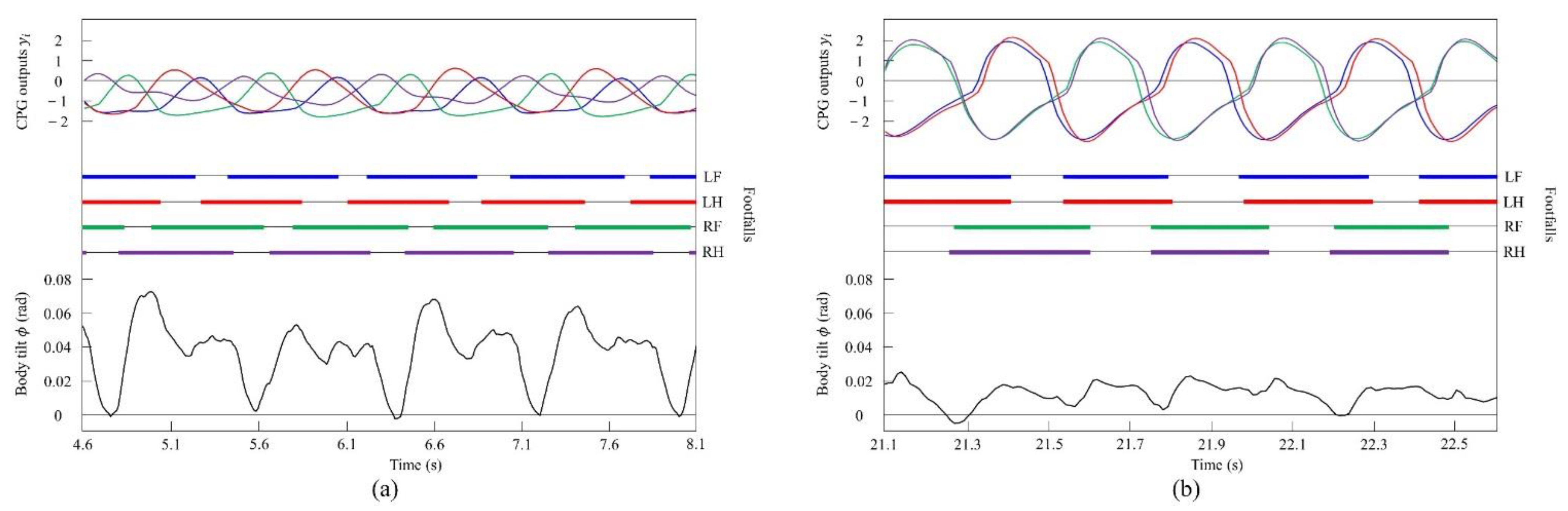
By contrast, only was changed, and we allowed Spinalbot with vestibular modulation () to locomote from low to medium speeds, as shown in Figure 12. In this case, different gaits appeared according to the speed. Walking emerged at low speeds, and the gait shifted to pacing as the speed increased. At low speeds (0.15 to 0.23 m/s of Figure 12), walking in which the leg moved in the order LF−RH−RF−LH, as shown in Figure 13a, emerged. At medium speeds (0.23 to 0.35 m/s of Figure 12), as shown in Figure 13b, the gait shifted to pacing in which the leg moved simultaneously with the pair of LF and LH and with the pair of RF and RH, respectively, and the pairs moving in reverse. As in Section 4.2.1, and as shown in Figure 13a,b, the body tilt angle during walking was larger than that during pacing.
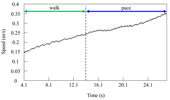
Figure 12.
Speeds during gait transition from walking to pacing.
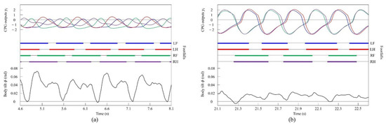
Figure 13.
Experimental results for walking and pacing at low and medium speeds, respectively: (a) a walk at 0.17 m/s and (b) a pace at 0.29 m/s. LF, LH, RF, and RH represent left foreleg, left hind leg, right foreleg, and right hind leg, respectively. CPG outputs are colored as follows: LF: blue; LH: red; RF: green; and RH: purple. The footfalls are indicated by thick line segments. The black wavy line represents body tilt (positive when facing down).
4.3.2. Gait Transition from Pacing to Galloping with Vestibular Modulation
By changing the speed parameter as shown in Figure 7b, we allowed Spinalbot to locomote at medium to high speeds. As in Section 4.3.1, it was confirmed by experiments that no gait other than pacing appeared in running without vestibular modulation, and that changes in the values of speed parameters had no effect on gait transition.
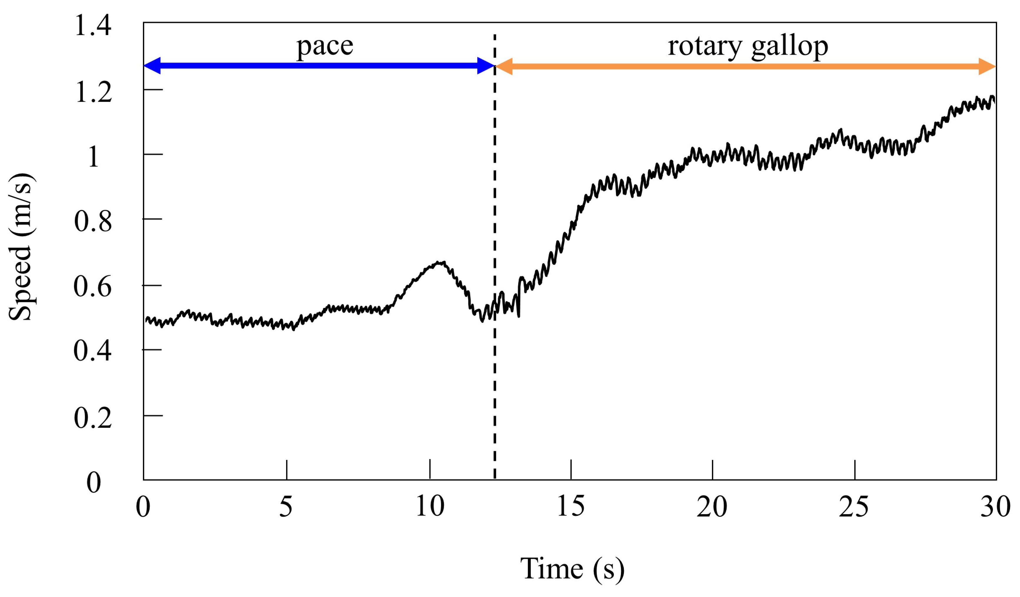
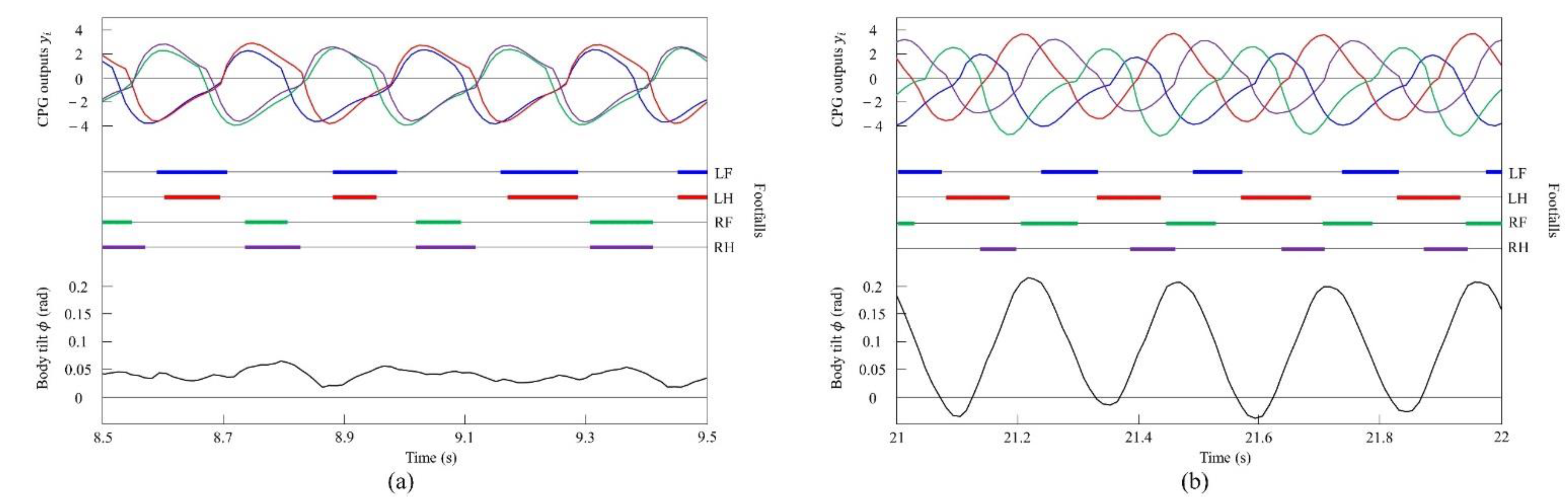
When locomoting Spinalbot without vestibular modulation using the speed parameters shown in Figure 7b, the gait was a pace at all speeds, but running with a flight phase became unstable. By contrast, only was changed, and we allowed Spinalbot with vestibular modulation () from medium to high speeds as shown in Figure 14. In this case, different gaits appeared at high speeds. Although the value of is different from that in Section 4.3.1, gait transition is possible with the same value; however, the value was changed so that the phase difference between legs become more prominent. The gait at medium speeds was a pace, but at high speeds, when a flight phase is generated, a gait transition to rotary gallop occurred and stable running became possible. At medium speeds (0.5 to 0.7 m/s of Figure 14), the gait is a pace, as shown in Figure 15a. At high speeds (0.7 to 1.2 m/s of Figure 14), the gait shifts to a rotary gallop in which the leg moves in the order LF−LH−RH−RF, as shown in Figure 15b. As shown in Figure 15a,b, the body tilt angle during galloping was larger than that during pacing. As shown in Figure 11 and Figure 15, the same phenomenon as in the simulation appeared, indicating that the change in the vibration of the trunk according to the speed is the factor of gait emergence.

Figure 14.
Speeds during gait transition from pacing to galloping.
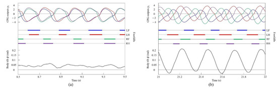
Figure 15.
Experimental results for pacing and galloping at medium and high speeds, respectively: (a) a pace at 0.5 m/s and (b) a rotary gallop at 1.0 m/s. LF, LH, RF, and RH represent left foreleg, left hind leg, right foreleg, and right hind leg, respectively. CPG outputs are colored as follows: LF: blue; LH: red; RF: green; and RH: purple. The footfalls are indicated by thick line segments. The black wavy line represents body tilt (positive when facing down).
4.4. Vestibular Modulation Level
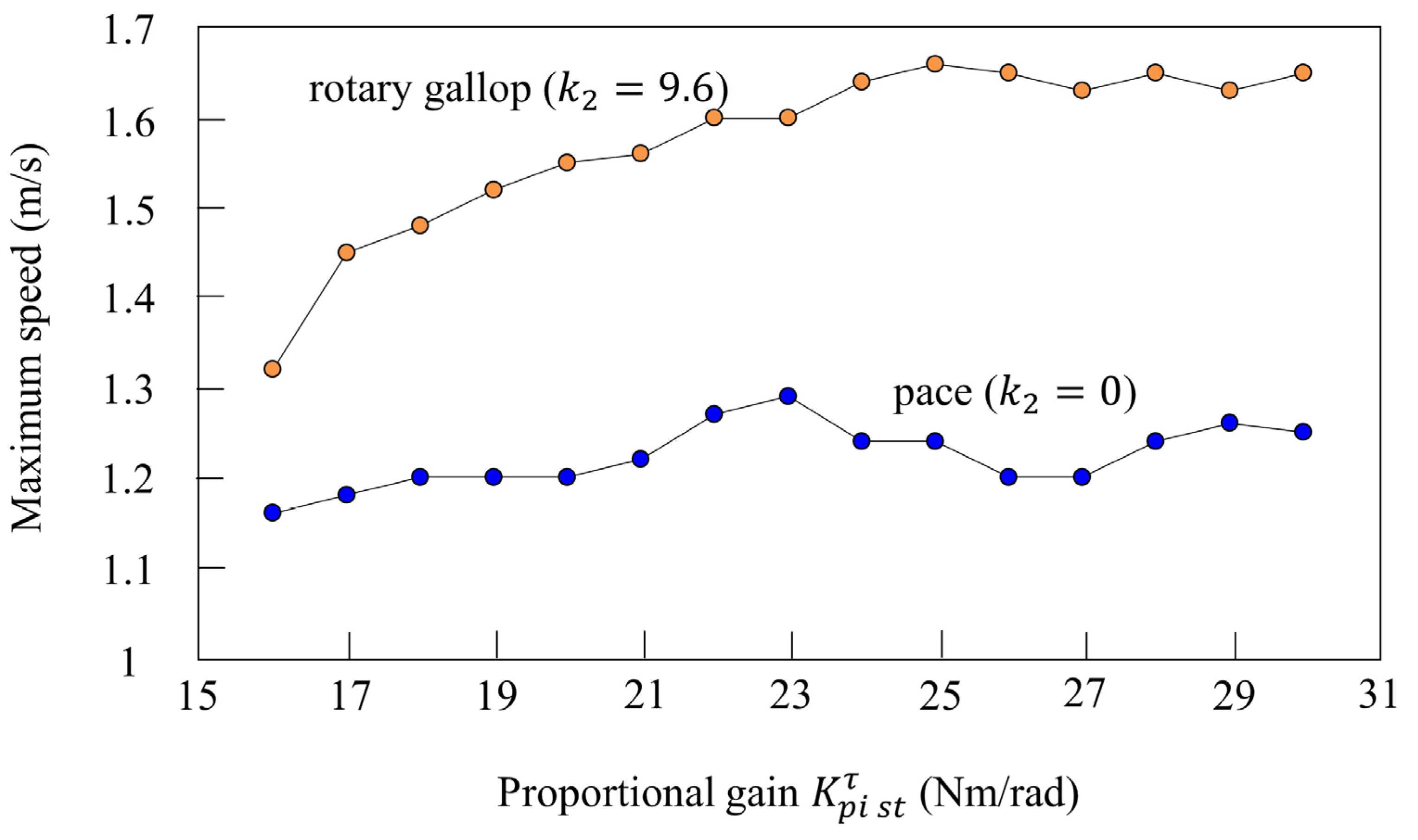
We investigated the effect of vestibular modulation ( or ) in simulation. Figure 16 shows the relationship between the proportional gain of the rotary joint and the maximum speed. First, the orange plots show the maximum speed when only was changed in various parameters that achieve locomotion at 12 s while galloping in Figure 10. Rotary gallop emerged in all cases where was between 16 and 30 Nm/rad without changing , and stable running was possible. In addition, the maximum speed increased according to the value of . The blue plots show the results of a similar simulation without vestibular modulation. In the section where Nm/rad or less, the maximum speed increased according to , but it did not increase after that. The leg swing speed increased according to the proportional gain, but it is considered that the effective propulsive force decreased because the body vibration and the leg vibration did not synchronize without vestibular modulation. Furthermore, regardless of , the maximum speed was higher with vestibular modulation than without. From these results, is robust to the proportional gain, which is one of the speed parameters, in terms of achieving gait transition.
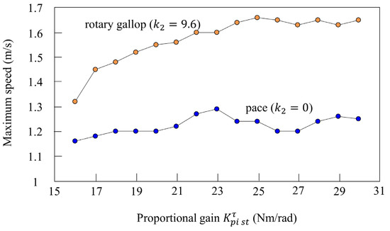
Figure 16.
Relationship between the speed parameter and maximum speed. The plot shows the maximum speed at each proportional gain. The plot colors are as follows: with vestibular modulation: orange; without vestibular modulation: blue.
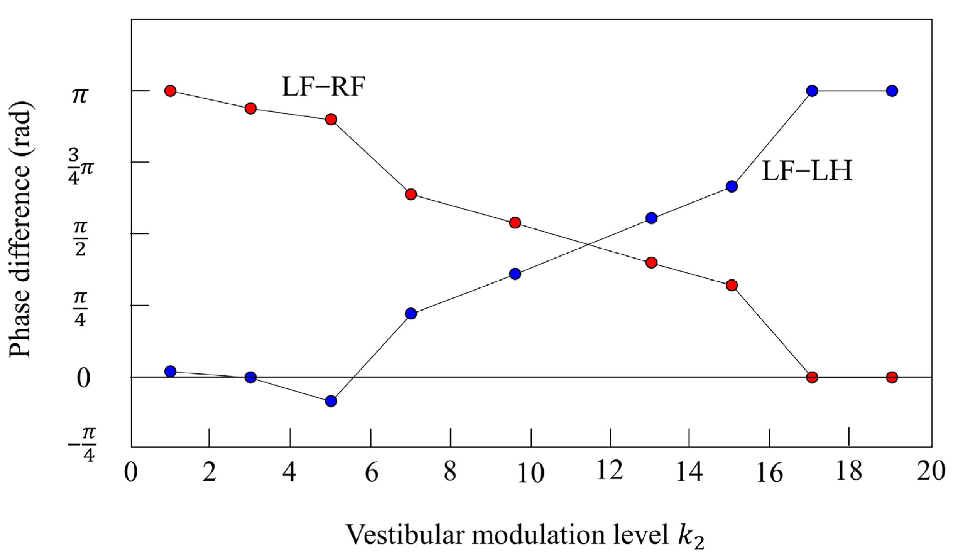
Furthermore, we investigated the relationship between and the phase difference between the legs. Figure 17 shows the results when only was changed in various parameters that achieved locomotion at 12 s while galloping in Figure 10. The red plots show the phase difference between the left foreleg and the right foreleg, and the blue plots show the phase difference between the left foreleg and the left hind leg. When the value is low (), the influence of vestibular feedback is small and a pace is kept. On the other hand, if the value is high (), the influence of vestibular feedback becomes very large and, instead of a rotary gallop, a bound appears in which the phase of the foreleg and the phase of the hind leg are opposite and the phase of the left leg and the phase of the right leg are in phase. However, Figure 17 shows that the value of was robust in the wide range. At 0.4 m/s or less, walking appeared in the range of from 1 to 19, but at less than 1, only a pace appeared.
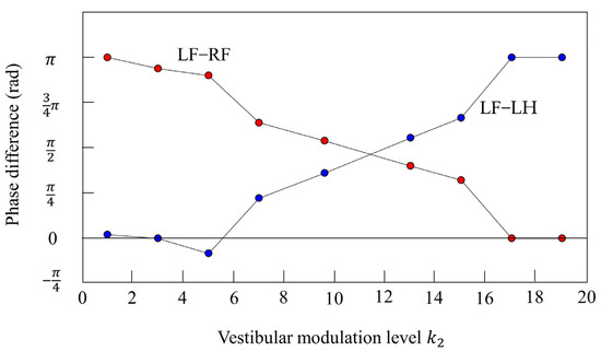
Figure 17.
Relationship between the vestibular modulation level and phase difference. The plot shows the phase difference at each vestibular modulation level . The red plot shows the phase difference between the left foreleg and the right foreleg (LF−RF). The blue plot shows the phase difference between the left foreleg and the left hind leg (LF−LH).
5. Discussion
The ipsilateral pairs should have been in phase because the CPGs were coupled to produce a pace. However, due to the effect of the body tilt angle feedback, a phase difference occurred between the two legs and, consequently, walking and galloping, which are different gaits from pace, appeared. The results of both the simulation experiments and the robot experiments show that the appearance of either walking or galloping depends on the difference in the ratio of the vibration frequency of each leg to the vibration frequency of the body. The details are described below.
5.1. Principle Emergence of Walking
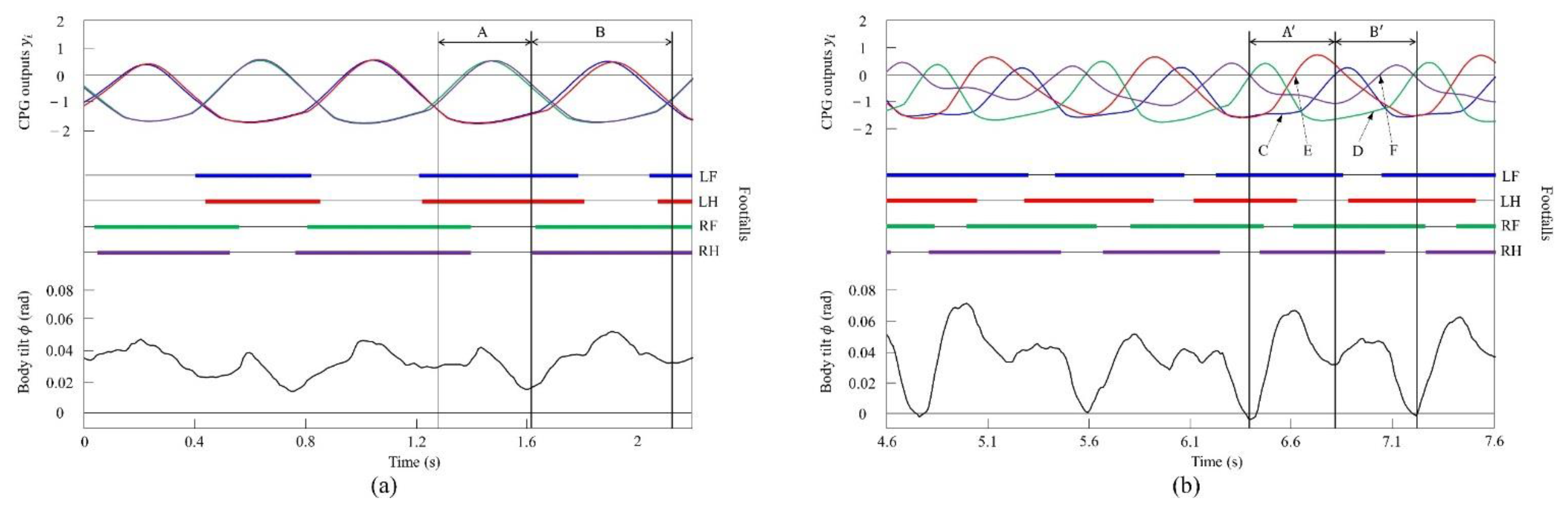
Figure 18a shows the CPG outputs, the footfalls, and the body tilt when locomoting in a pace immediately before the transition to walk. In addition, Figure 18b shows the data for walking. As shown in (A) of Figure 18a, the torso is tilted forward during the support phase of the left foreleg and the left hind leg. As shown in (A’) of Figure 18b, the extensor neuron of the left foreleg is activated by the effect of vestibular feedback and, consequently, the support phase of the left foreleg is extended (C). By contrast, the left hind leg is switched to the swing phase because the flexor neuron is activated (E). As a result, in Figure 18a, the left foreleg and the left hind leg touch the ground at the same time, but in Figure 18b, the left hind leg and the left foreleg touch in this order. As shown in (B) of Figure 18a, the torso is tilted forward in the support phase of the right foreleg and the right hind leg, as in (A). As shown in (B’) of Figure 18b, the extensor neuron of the right foreleg is activated by the effect of vestibular feedback and, consequently, the support phase of the right foreleg is extended (D). However, the right hind leg is switched to the swing phase because the flexor neuron is activated (F). As a result, in Figure 18a, the right foreleg and right hind leg touch the ground at the same time, but in Figure 18b, the right hind leg and the right foreleg touch in this order. As described above, as a result of autonomously modifying the CPG outputs according to the body tilt angle, a walk appeared as shown in Figure 18b.
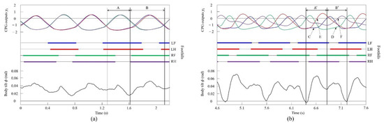
Figure 18.
Experimental results for (a) a pace at a speed of 0.1 m/s and (b) a walk at a speed of 0.17 m/s. CPG outputs are colored as follows: LF: blue; LH: red; RF: green; and RH: purple. The footfalls are indicated by the thick line segments. The black trajectory represents the body tilt. A, A’, B, and B’ indicate periods while tilting forward. C and D indicate that the extensor neurons are activated. E and F indicate that the flexor neurons are activated.
5.2. Principle Emergence of Galloping
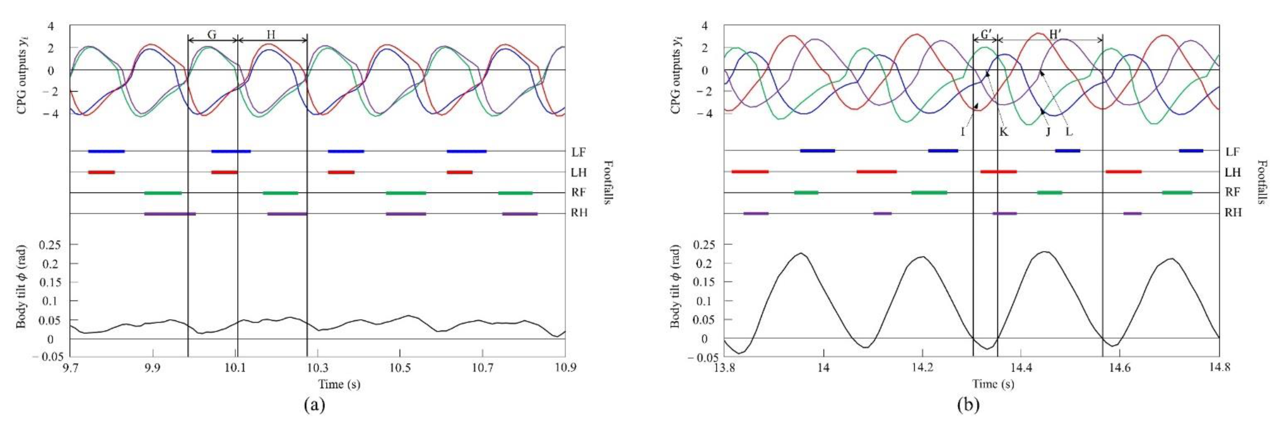
Figure 19a shows the CPG outputs, the footfalls, and the body tilt when locomoting in a pace immediately before the transition to a gallop. In addition, Figure 19b shows the data for galloping. As shown in (H) of Figure 19a, the torso is tilted forward during the support phase of the right foreleg and the right hind leg. As shown in (H’) of Figure 19b, the extensor neuron of the right foreleg is activated by the effect of vestibular feedback and, as a result, the support phase of the right foreleg is extended (J). By contrast, the right hind leg is switched to the swing phase because the flexor neuron is activated (L). As shown in (G) of Figure 19a, when traveling at a pace, the center of vibration of the torso tends to be biased forward; therefore, the torso does not tilt backward, but, as a result, it transitions to a rotary gallop. This is because the torso tilts greatly forward when the right fore and hind legs are supported, and the left foreleg and right foreleg approach the same phase by modifying with vestibular feedback. Therefore, a strong recoil occurs because of the kicking of the two forelegs. As a result, the torso also tilts backward. Therefore, as shown in (G’) of Figure 19b, the flexor neuron of the left foreleg is activated by the effect of vestibular feedback and, as a result, the left foreleg is switched to the swing phase (K). Finally, regarding the left hind leg, the extensor neuron is activated, and the support phase of the left hind leg is extended (I). As described above, a rotary gallop that tilts backward appears, as shown in Figure 19b.
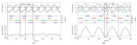
Figure 19.
Experimental results for (a) a pace at a speed of 0.6 m/s and (b) a rotary gallop at a speed of 0.7 m/s. CPG outputs are colored as follows: LF: blue; LH: red; RF: green; and RH: purple. The footfalls are indicated by the thick line segments. The black trajectory represents the body tilt. G and G’ indicate periods while tilting backward. H and H’ indicate periods while tilting forward. I and J indicate that the extensor neurons are activated. K and L indicate that the flexor neurons are activated.
5.3. Difference between Factors behind Emergence of Walking and Galloping
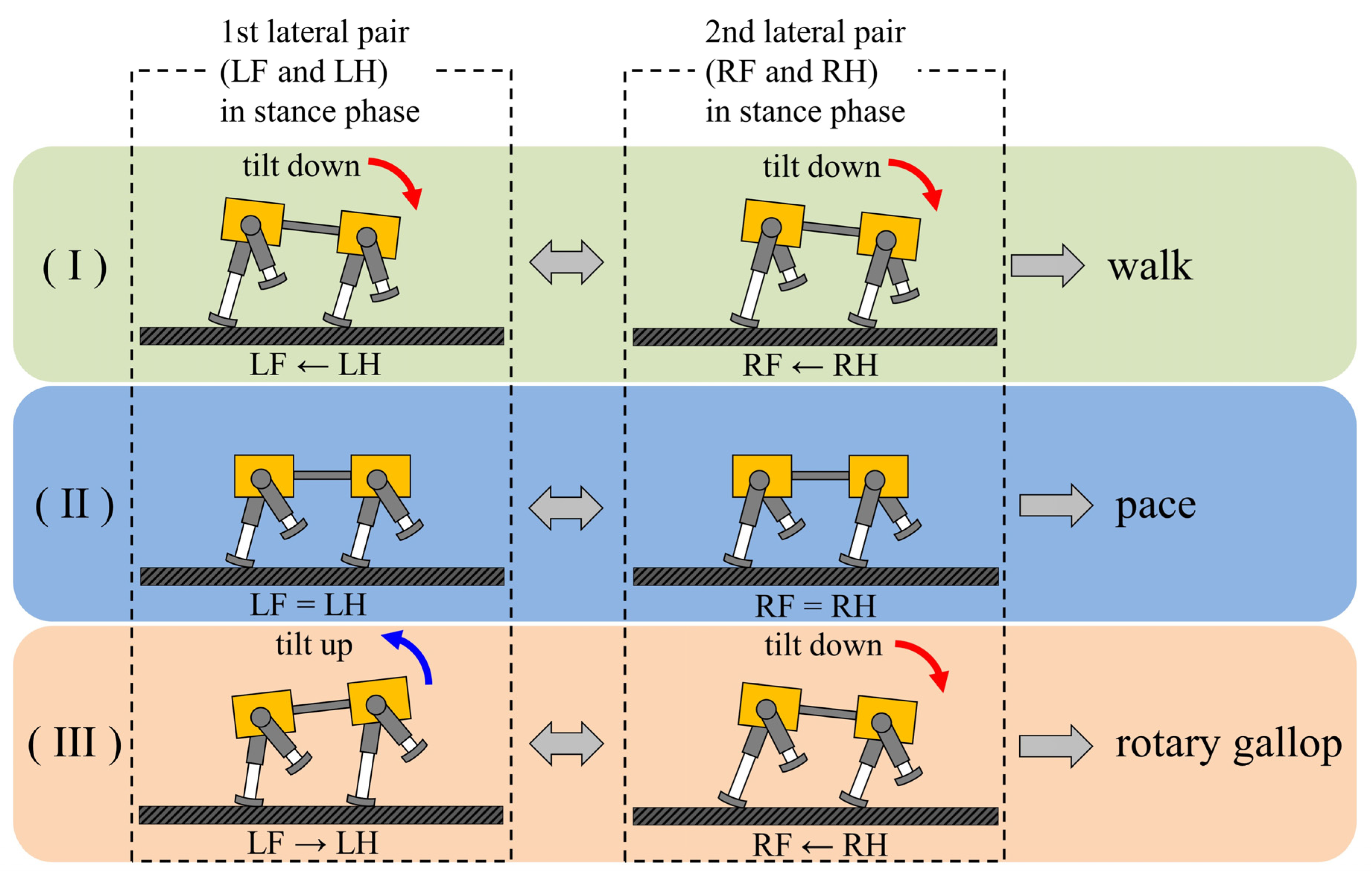
A walk and a rotary gallop emerge in the same way, using vestibular feedback. As shown Figure 20, it was found that the two types of gaits were derived from the fact that the ratio of the vibration frequency of the torso to the vibration frequency of each leg differed between walking and running. At low speeds, the leg elasticity is set to be low to avoid chattering when the leg touches the ground; therefore, the ratio was 2:1, as shown in Figure 9a and Figure 13a. This means that the torso vibrates twice in one cycle of leg vibration with the same tendency, as shown in (A) and (B) of Figure 18a, and in (A’) and (B’) of Figure 18b. Specifically, as shown in Figure 20I, when the pair of the left foreleg and left hind leg (1st lateral pair) is in the stance phase, the body tilts down. Therefore, the leg phase switches from the stance phase to the swing phase in the order of the left hind leg and the left foreleg. Similar to the 1st lateral pair, the body tilts down when the pair of the right foreleg and the right hind leg (2nd lateral pair) is in the stance phase. Therefore, the leg phase switches from the stance phase to the swing phase in the order of the right hind leg and the right foreleg. The result is a walk.
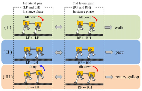
Figure 20.
The principle of gait generation and transition: (I) walk, (II) pace, (III) rotary gallop. The order of switching from the stance phase to swing phase in the lateral pair is listed below the robot diagram.
On the other hand, the leg elasticity can be set to high to allow large jumps at high speeds. As a result, the repulsive force of the leg due to the contraction of the leg during the support phase increases, and it becomes possible to make a large jump and run. Consequently, the torso vibrates once in one cycle of leg vibration (sinking, lifting, and jumping) and, at high speeds, the ratio of the torso vibration frequency to the leg vibration frequency was 1:1, as shown in Figure 11b and Figure 15b. Specifically, as shown in Figure 20III, when the pair of the right foreleg and the right hind leg (2nd lateral pair) is in the stance phase, the body tilts down. Therefore, the leg phase switches from the stance phase to the swing phase in the order of the right hind leg and the right foreleg. Due to the influence of the phase difference that occurred in the 2nd lateral pair, the body tilts backward when the pair of the left foreleg and the left hind leg (1st lateral pair) is in the stance phase. Therefore, the effect of vestibular feedback is reversed compared to the 2nd lateral pair, and the leg phase switches from the stance phase to the swing phase in the order of the left foreleg and the left hind leg. The result is a rotary gallop. In this way, as the body vibration frequency differs depending on the speed range, the effect of vestibular feedback is the same for the 1st lateral pair and 2nd lateral pair at low speeds, but the opposite at high speeds. This is the reason different gaits emerge with the same method. The difference in the ratio of the body vibration frequency to the leg vibration frequency depending on the speed range has also been pointed out in a previous study [31]. Geyer et al. clarified that the ratio in bipedal locomotion is 2:1 when walking and 1:1 when running [40]. If the ipsilateral legs are regarded as one leg in a pace, then the movement of Spinalbot is similar to bipedal walking. In addition, as shown in Section 4.2 and Section 4.3, the body vibration becomes very small at medium speeds. As shown in Figure 20II, the effect of vestibular feedback is very small in both the 1st lateral pair and 2nd lateral pair. As a result, the phase difference between the foreleg and hind leg becomes very small in both pairs, and the gait becomes the default gait pace. By changing the speed parameters as shown in Figure 6 and Figure 7, the leg elasticity and leg cycle are different at each speed, so the dynamics of the physical model change according to the speed. Specifically, the ratio of body vibration to leg vibration was 2:1 at low speeds and 1:1 at high speeds, and the body vibration was very small at medium speeds. It is considered that the CPG of each leg was modified according to the change in body vibration through the body tilt angle feedback and, as a result, different gaits appeared in each speed range.
5.4. Transition Speed
In the simulation, as shown in Figure 8, the gait transitioned to a pace at 0.4 m/s and, in Figure 10, it transitioned to a rotary gallop at 1.0 m/s. In the robot experiment, as shown in Figure 12, the gait transitioned to a pace at 0.23 m/s and, in Figure 14, it transitioned to a rotary gallop at 0.7 m/s. The factor that determines the transition speed is considered to be mechanical features. The vibration frequency of the torso differs depending on the size of the body, and it is fed back to the CPG, which is a factor that determines the transition speed. The effect of the speed parameter on transition speed has been investigated by Fukuoka et al. [46]. According to the survey, even if the acceleration was changed by changing the speed parameter, the transition speed did not change. Other parameters need to be investigated, but at least they do not depend on acceleration. In addition, Habu et al. reported the relationship between the type of terrain and the transition speed [45] and, when climbing a slope, trotting is maintained even at the speed at which a walk appears on flat ground. Therefore, the transition speed is considered to be affected by the type of terrain; however, note that the experimental results shown in Section 4.2 and Section 4.3 were carried out on flat ground.
5.5. Related Works
According to our research, a quadruped robot that achieves gait transitions between walk, pace, and rotary gallop has not yet been developed. Owaki et al. [47] achieved an autonomous gait transition between walk, pace, and rotary gallop according to speed with a quadruped simulation model by feeding back the leg load and neck joint angle to the CPG. However, the gait transition is determined by the movement of the head and neck via the neck joint angle feedback, and therefore depends on the model shape (neck length and elastic force of the neck joint). By contrast, our proposed method (vestibular modulation) is versatile because the gait transition is caused by only the body tilt angle feedback; therefore, it can be applied to robots without a head and neck. In addition, even if the robot mechanism is the same, it is possible to achieve both gait transitions between walk, trot, and transverse gallop and between walk, pace, and rotary gallop just by rearranging the underlying CPG network. This was demonstrated in the actual robot Spinalbot, which showed its high versatility. Furthermore, the sensor for measuring the body tilt angle is inexpensive, and because it is mounted on the body, the impact received by the legs is not easily transmitted; therefore, it is considered to be excellent in mounting.
Suzuki et al. reported that a walk is generated by feedback of the joint torque to the CPG, and that the speed increased and the energy consumption improved [48]. We have achieved similar results in our previous work [32], which demonstrated that when the gait transitioned from a trot to a gallop, the speed increased sharply and the energy consumption decreased. A similar effect is expected in the gait transition from a pace to a rotary gallop.
6. Conclusions
We achieved an autonomous gait transition between walk, pace, and rotary gallop using a quadruped robot with a pace as the basic gait. By simply controlling the quadruped robot with a simple method that combined central pattern generators (CPG) and feeding the body tilt back to the CPG, walk and rotary gallop (which are not specified in the program) emerged and autonomous gait transitions were achieved. The appearance of walk and rotary gallop is the result of modifying the phase of each leg according to the body vibration that changes due to the change in velocity. We have already reported that walk and transverse gallop emerge autonomously from a CPG network with a basic gait set to trot by using a similar method. Furthermore, in this paper, we reported that the same gait transition phenomenon as that observed in an actual animal can be achieved just by setting the CPG network so that the basic gait is a pace. Therefore, our proposed method is considered to be effective for quadruped robots where the basic gaits are both trot and pace.
By changing the value of the CPG parameter, it may be possible to change the default gait to another gait. However, we proposed a method in which the default gait is trot or pace, and the gait autonomously transitioned according to the locomotion state. Quadruped robots such as Spot [19], which will soon be put into practical use, uses a trot; however, autonomously changing its gait could make walking more stable. We consider that the transition from pace in this paper has the same effect. Therefore, we consider that the achievement of transitions from trot and pace, of which we claim, is sufficiently practical for quadruped robots. In our previous works [32], we showed that it is possible to stabilize the posture at high speeds, reduce energy consumption, and adapt to rough terrain by making a gait transition from trot to transverse gallop. The same effects are expected by making a gait transition from pace to rotary gallop.
As shown in Figure 10 and Figure 14, it cannot be said that the maximum speed is fast. The reason the maximum speed is limited is that Spinalbot does not have a spine and that each leg has one rotary joint. Possibilities for increasing the maximum speed are the addition of a spine and the adoption of three-joint legs, as in animals.
There are studies that achieve complex locomotion by machine learning methods [49,50]. They perform the adjustment or optimization of control parameters, including CPG parameters, by a learning method based on a lot of sensing information. As a result, advanced locomotions (e.g., turning) are achieved. In our achievements, learning based on sensory information was not applied, but the emergence of the two gaits and the stable running was achieved. By combining the proposed method of the autonomous leg phase modulation with the methods to determine the motion plan by machine learning, more advanced locomotions such as turning and climbing are expected. Furthermore, a method has been proposed to achieve walking by learning in a simulation and implementing the result on a robot [51,52]. This method reduces the number of sensors and does not require many experiments, but it does not allow it to run through unperceived obstacles. In our previous work [32], we achieved galloping on unperceived rough terrain without learning. Furthermore, our proposed method only uses a single sensor unit to measure the body tilt angle and can therefore contribute not only to achieving gait transition but also to adapting to unperceived environments.
Supplementary Materials
The following supporting information can be downloaded at: https://www.mdpi.com/article/10.3390/robotics11010003/s1, Video S1: Gait transition experiments.
Author Contributions
Conceptualization, Y.F.; data curation, T.F., S.M. and Y.H.; formal analysis, T.F.; funding acquisition, Y.F.; investigation, T.F., S.M. and Y.H.; methodology, T.F. and Y.H.; project administration, Y.F.; software, T.F. and Y.H.; validation, Y.F.; visualization, T.F.; writing—original draft, T.F.; writing—review and editing, T.F. All authors have read and agreed to the published version of the manuscript.
Funding
This work was supported by the Japan Society for the Promotion of Science (Grant-in-Aid for Scientific Research (C), Grant Number: 18K11489).
Institutional Review Board Statement
Not applicable.
Informed Consent Statement
Not applicable.
Data Availability Statement
Not applicable.
Acknowledgments
We would like to thank Yoshikazu Mori, Naoji Shiroma, and Kousuke Inoue for their valuable comments and advice. We would like to thank our colleges for their contribution to the results.
Conflicts of Interest
The authors declare no conflict of interest.
References
- Muybridge, E. Animal in Motion; Dover Publications: New York, NY, USA, 1957. [Google Scholar]
- Hildebrand, M. The adaptive significance of tetrapod gait selection. Am. Zool. 1980, 20, 255–267. [Google Scholar] [CrossRef]
- Hudson, P.E.; Corr, S.A.; Wilson, A.M. High speed galloping in the cheetah (Acinonyx jubatus) and the racing greyhound (Cains familiaris): Spatio-temporal and kinetic characteristics. J. Exp. Biol. 2012, 215, 2425–2434. [Google Scholar] [CrossRef] [PubMed] [Green Version]
- Schmiedeler, J.P.; Waldron, K.J. The mechanics of quadrupedal galloping and the future of legged vehicles. Int. J. Robot. Res. 1999, 18, 1224–1234. [Google Scholar] [CrossRef]
- Hawker, G.; Buehler, M. Quadruped trotting with passive knees: Design, control, and experiments. In Proceedings of the IEEE International Conference on Robotics and Automation (ICRA), San Francisco, CA, USA, 24–28 April 2000; pp. 24–28. [Google Scholar]
- Raibert, M.; Blankespoor, K.; Nelson, G.; Playter, R. BigDog, the rough-terrain quadruped robot. In Proceedings of the 17th World Congress. The International Federation of Automatic Control (IFAC), Seoul, Korea, 6–11 July 2008; Volume 41, pp. 10822–10825. [Google Scholar]
- Nakatani, K.; Sugimoto, Y.; Osuka, K. Demonstration and analysis of quadrupedal passive dynamic walking. Adv. Robot. 2009, 23, 483–501. [Google Scholar] [CrossRef]
- Santos, C.P.; Matos, V. Gait transition and modulation in a quadruped robot: A brainstem-like modulation approach. Robot. Auton. Syst. 2011, 59, 620–634. [Google Scholar] [CrossRef] [Green Version]
- Moro, F.L.; Spröwitz, A.; Tuleu, A.; Vespignani, M.; Tsagarakis, N.G.; Ijspeert, A.J.; Caldwell, D.G. Horse-like walking, trotting and galloping derived from kinematic motion primitives(kMPs) and their application to walk/trot transitions in a compliant quadruped robot. Biol. Cybern. 2013, 107, 309–320. [Google Scholar] [CrossRef] [Green Version]
- Gehring, C.; Coros, S.; Hutter, M.; Bloesch, M.; Hoepflinger, M.A.; Siegwart, R. Control of dynamic gaits for a quadrupedal robot. In Proceedings of the IEEE International Conference on Robotics and Automation (ICRA), Karlsruhe, Germany, 6–10 May 2013. [Google Scholar] [CrossRef] [Green Version]
- Spröwitz, A.; Tuleu, A.; Vespignani, M.; Ajallooeian, M.; Badri, E.; Ijspeert, A.J. Towards dynamic trot gait locomotion: Design, control, and experiments with Cheetah-cub, a compliant quadruped robot. Int. J. Robot. Res. 2013, 32, 932–950. [Google Scholar] [CrossRef] [Green Version]
- Hutter, M.; Gehring, C.; Höpflinger, M.A.; Blösch, M.; Siegwart, R. Toward combining speed, efficiency, versatility, and robustness in an autonomous quadruped. IEEE Trans. Robot. 2014, 30, 1427–1440. [Google Scholar] [CrossRef]
- Li, M.; Jiang, Z.; Wang, P.; Sun, L.; Ge, S.S. Control of a quadruped robot with bionic springy legs in trotting gait. J. Bionic Eng. 2014, 11, 188–198. [Google Scholar] [CrossRef]
- Koo, I.M.; Trong, T.D.; Lee, Y.H.; Moon, H.; Koo, J.; Park, S.; Choi, H.R. Biologically inspired gait transition control for a quadruped walking robot. Auton. Robot. 2015, 39, 169–182. [Google Scholar] [CrossRef]
- Semini, C.; Barasuol, V.; Boaventura, T.; Frigerio, M.; Focchi, M.; Caldwell, D.G.; Buchli, J. Towards versatile legged robots through active impedance control. Int. J. Robot. Res. 2015, 34, 1003–1020. [Google Scholar] [CrossRef]
- Hyun, D.J.; Lee, J.; Park, S.; Kim, S. Implementation of trot-to-gallop transition and subsequent gallop on the MIT Cheetah I. Int. J. Robot. Res. 2016, 35, 1627–1650. [Google Scholar] [CrossRef]
- Kitano, S.; Hirose, S.; Horigome, A.; Endo, G. TITAN-XIII: Sprawling-type quadruped robot with ability of fast and energy-efficient walking. ROBOMECH J. 2016, 3. [Google Scholar] [CrossRef]
- Hutter, M.; Gehring, C.; Lauber, A.; Gunther, F.; Bellicoso, C.D.; Tsounis, V.; Fankhauser, P.; Diethelm, R.; Bachmann, S.; Bloesch, M.; et al. ANYmal—Toward legged robots for harsh environments. Adv. Robot. 2017, 31, 918–931. [Google Scholar] [CrossRef]
- Boston Dynamics, Spot. Available online: http://www.bostondynamics.com/ (accessed on 9 December 2021).
- Grillner, S. Handbook of Physiology; John Wiley & Sons: Hoboken, NJ, USA, 1981; pp. 1179–1236. [Google Scholar]
- Golubitsky, M.; Stewart, I.; Buono, P.L.; Collins, J.J. Symmetry in locomotor central pattern generators and animal gaits. Nature 1999, 401, 693–695. [Google Scholar] [CrossRef]
- Ito, S.; Yuasa, H.; Luo, Z.W.; Ito, M.; Yanagihara, D. A mathematical model of adaptive behavior in quadruped locomotion. Biol. Cybern. 1998, 78, 337–347. [Google Scholar] [CrossRef]
- Tsujita, K.; Tsuchiya, K.; Onat, A. Adaptive gait pattern control of a quadruped locomotion robot. In Proceedings of the IEEE/RSJ International Conference on Intelligent Robots and Systems (IROS), Maui, HI, USA, 29 October–3 November 2001. [Google Scholar] [CrossRef]
- Tsujita, K.; Kobayashi, T.; Inoura, T.; Masuda, T. Gait transition by tuning muscle tones using pneumatic actuators in quadruped locomotion. In Proceedings of the IEEE/RSJ International Conference on Intelligent Robots and Systems (IROS), Nice, France, 22–26 September 2008. [Google Scholar] [CrossRef]
- Harischandra, N.; Knuesel, J.; Kozlov, A.; Bicanski, A.; Cabelguen, J.M.; Ijspeert, A.; Ekeberg, Ö. Sensory feedback plays a significant role in generating walking gait and in gait transition in salamanders: A simulation study. Front. Neurorobotics 2011, 5, 3. [Google Scholar] [CrossRef] [Green Version]
- Aoi, S.; Yamashita, T.; Tsuchiya, K. Hysteresis in the gait transition of a quadruped investigated using simple body mechanical and oscillator network models. Phys. Rev. E 2011, 83, 061909. [Google Scholar] [CrossRef] [Green Version]
- Kimura, H.; Akiyama, S.; Sakurama, K. Realization of dynamic walking and running of the quadruped using neural oscillator. Auton. Robot. 1999, 7, 247–258. [Google Scholar] [CrossRef]
- Fukuoka, Y.; Kimura, H.; Cohen, A.H. Adaptive dynamic walking of a quadruped robot on irregular terrain based on biological concepts. Int. J. Robot. Res. 2003, 22, 187–202. [Google Scholar] [CrossRef]
- Fukuoka, Y.; Kimura, H. Dynamic locomotion of a biomorphic quadruped‘Tekken ’robot using various gaits: Walk, Trot, Free-Gait and Bound. Appl. Bionics Biomech. 2009, 6, 63–71. [Google Scholar] [CrossRef]
- Aoi, S.; Katayama, D.; Fujiki, S.; Tomita, N.; Funato, T.; Yamashita, T.; Senda, K.; Tsuchiya, K. A stability-based mechanism for hysteresis in the walk-trot transition in quadruped locomotion. J. R. Soc. Interface 2013, 10, 20120908. [Google Scholar] [CrossRef] [Green Version]
- Fukuoka, Y.; Habu, Y.; Fukui, T. Analysis of the gait generation principle by a simulated quadruped model with a CPG incorporating vestibular modulation. Biol. Cybern. 2013, 107, 695–710. [Google Scholar] [CrossRef] [PubMed]
- Fukui, T.; Fujisawa, H.; Otaka, K.; Fukuoka, Y. Autonomous gait transition and galloping over unperceived obstacles of a quadruped robot with CPG modulated by vestibular feedback. Robot. Auton. Syst. 2019, 111, 1–19. [Google Scholar] [CrossRef]
- Fukuoka, Y.; Habu, Y.; Fukui, T. A simple rule for quadrupedal gait generation determined by leg loading feedback: A modeling study. Sci. Rep. 2015, 5, 8169. [Google Scholar] [CrossRef] [Green Version]
- Owaki, D.; Ishiguro, A. A quadruped robot exhibiting spontaneous gait transitions from walking to trotting to galloping. Sci. Rep. 2017, 7, 277. [Google Scholar] [CrossRef]
- Kimura, H.; Shimoyama, I.; Miura, H. Dynamics in the dynamic walk of a quadruped robot. Adv. Robot. 1989, 4, 283–301. [Google Scholar] [CrossRef] [Green Version]
- Raibert, M.H. Trotting, pacing and bounding by a quadruped robot. J. Biomech. 1990, 23, 79–81, 83–98. [Google Scholar] [CrossRef]
- Sano, A.; Furusho, J. Realization of dynamic quadruped locomotion in pace gait by controlling walking cycle. In Experimental Robotics II; Springer: Berlin/Heidelberg, Germany, 2005; pp. 491–502. [Google Scholar]
- Homby, G.S.; Takamura, S.; Yamamoto, T.; Fujita, M. Autonomous evolution of dynamic gaits with two quadruped robots. IEEE Trans. Robot. 2005, 21, 402–410. [Google Scholar]
- Smith, J.A.; Poulakakis, I. Rotary gallop in the untethered quadrupedal robot scout II. In Proceedings of the IEEE/RSJ International Conference on Intelligent Robots and Systems (IROS), Sendai, Japan, 28 September–2 October 2004. [Google Scholar] [CrossRef]
- Geyer, H.; Seyfarth, A.; Blickhan, R. Compliant leg behavior explains basic dynamics of walking and running. Proc. R. Soc. B 2006, 273, 861–2867. [Google Scholar] [CrossRef] [Green Version]
- Matsuoka, K. Mechanisms of frequency and pattern control in the neural rhythm generators. Biol. Cybern. 1987, 56, 345–353. [Google Scholar] [CrossRef]
- Andersson, O.; Grillner, S. Peripheral control of the cat’s step cycle: II. Entrainment of the central pattern generators for locomotion by sinusoidal hip movements during “fictive locomotion”. Acta Physiol. Scand. Banner 1983, 118, 229–239. [Google Scholar] [CrossRef] [PubMed]
- Duysens, J.; Clarac, F.; Cruse, H. Load-regulating mechanisms in gait and posture: Comparative aspects. Physiol. Rev. 2000, 80, 83–133. [Google Scholar] [CrossRef] [Green Version]
- Roberts, T.D. Neurophysiology of Postural Mechanisms; Butterworths: Oxford, UK, 1967. [Google Scholar]
- Habu, Y.; Uta, K.; Fukuoka, Y. Three-dimensional walking of a simulated muscle-driven quadruped robot with neuromorphic two-level central pattern generators. Int. J. Adv. Robot. Syst. 2019, 16. [Google Scholar] [CrossRef]
- Fukuoka, Y.; Fukino, K.; Habu, Y.; Mori, Y. Energy evaluation of a bio-inspired gait modulation method for quadrupedal locomotion. Bioinspiration Biomim. 2015, 10, 046017. [Google Scholar] [CrossRef] [PubMed]
- Suzuki, S.; Owaki, D.; Fukuhara, A.; Ishiguro, A. Quadruped gait transition from walk to pace to rotary gallop by exploiting head movement. In International Conference on Biomimetic and Biohybrid Systems; Springer: Cham, Switzerland, 2016; pp. 532–539. [Google Scholar]
- Suzuki, S.; Kano, T.; Ispeert, A.J.; Ishiguro, A. Sprawling quadruped robot driven by decentralized control with cross-coupled sensory feedback between legs and trunk. Front. Neurorobotics 2021, 14, 116. [Google Scholar] [CrossRef]
- Dürr, V.; Arena, P.P.; Cruse, H.; Dallmann, C.J.; Drimus, A.; Hoinville, T.; Krause, T.; Mátéfi-Tempfli, S.; Paskarbeit, J.; Patanè, L.; et al. Integrative biomimetics of autonomous hexapedal locomotion. Front. Neurorobotics 2019, 13, 88. [Google Scholar] [CrossRef]
- Manoonpong, P.; Patanè, L.; Xiong, X.; Brodoline, I.; Dupeyroux, J.; Viollet, S.; Arena, P.; Serres, J.R. Insect-inspired robots: Bridging biological and artificial systems. Sensors 2021, 21, 7609. [Google Scholar] [CrossRef] [PubMed]
- Calandra, M.; Patanè, L.; Sun, T.; Arena, P.; Manoonpong, P. Echo state networks for estimating exteroceptive conditions from proprioceptive states in quadruped robots. Front. Neurorobotics 2021, 15, 118. [Google Scholar] [CrossRef]
- Hwangbo, J.; Lee, J.; Dosovitskiy, A.; Bellicoso, D.; Tsounis, V.; Koltun, V.; Hutter, M. Learning agile and dynamic motor skills for legged robots. Sci. Robot. 2019, 4, 26. [Google Scholar] [CrossRef] [Green Version]

Publisher’s Note: MDPI stays neutral with regard to jurisdictional claims in published maps and institutional affiliations. |
© 2021 by the authors. Licensee MDPI, Basel, Switzerland. This article is an open access article distributed under the terms and conditions of the Creative Commons Attribution (CC BY) license (https://creativecommons.org/licenses/by/4.0/).