1. Introduction
Over the last few years, robots with soft bodies [
1] have captured significant interest and represent a growing trend. Soft robotics allows the design and development of complex systems able to adapt unstructured and hostile environment [
2]. They offer important advantages in several tasks, ranging from search and exploration missions [
3] to the cooperation with humans [
4]. Soft robots are typically divided in two categories: articulated [
5] and continuum ones [
6], and their design is often inspired by biological systems [
7]. Additionally, soft robots can span along all the spectrum between totally soft [
8] and rigid structures [
9].
Inflatable structures have been applied in the field of soft robotics because of their lightweight and physical compliance increasing payload-to-weight ratio. Moreover, their construction tends to reduce costs if compared with other lightweight solutions [
10]. Main disadvantages of these systems are low payload capacity, due to the actuation system and low stiffness, and complexity in kinematics and dynamics description [
11], due to non-linearities induced by large deformations in the material and multi-physical coupling.
Robots with rigid structures are employed in space environments, for on-board [
12] and off-board [
13] applications, executing tasks with great accuracy and generating high contact forces. Moreover, robots for space environments must be properly designed to satisfy strict requirements, such as weight and embarked volume. In space environments, deploying strategies mainly consist in mechanisms with interconnected bar elements [
14], or inflatable structure with pressure input [
15]. This second solution has been successfully used in space applications, where some of the most relevant projects are: the Inflatable Antenna Experiment (IAE) [
16], the inflatable and rigidable solar array [
17] and modular inflatable membranes of James Webb Space Telescope [
18].
In literature, soft robots can be described with approaches based on constant [
19] and non-constant curvature approximation [
20]. However, manipulators with inflatable links can be modeled considering traditional approaches developed for flexible link arms [
21], pseudo-rigid body models [
22] and simplified small deflection assumptions [
10]. The use of algorithms for the robot dynamic parameters identification, as shown in [
23], allows us to obtain a full dynamic description of manipulators, also considering the effects of temperature and mounting configuration [
24]. In soft robotics, several control approaches have been proposed. In [
25], a pressure control system has been used to perform the characterization of a soft joint for inflatable robotic arms (IRAs), actuated by two antagonist pneumatic artificial muscles (PAMs). In [
26], a pneumatically actuated humanoid robot, with two IRAs, is controlled using model predictive control (MPC) and linear quadratic regulation (LQR) in the joint space and in [
27] the MPC is compared against sliding mode control (SMC). In [
28], fuzzy logic allows a precise control of pneumatic actuated robots. Moreover, many control methods for soft robots are based on machine learning techniques, e.g., in [
29], where a neural network is used to control a cable-driven soft arm. Deep learning can lead to the development of visual servoing (VS) systems [
30]. Vision systems, widely used in robotics, can be especially useful for soft robots. In [
31], VS is used to have accurate shape control of a cable-driven soft manipulator, and in [
32] a vision-based controller is applied to soft robots to execute tasks without prior knowledge of system parameters. In [
33], SMC based on image processing algorithms is used to calculate real time path of robot motion.
When robots share the workspace with humans, the risk of an undesired collision during their operation must be minimized. Recently, the use of vision systems [
34,
35] with state estimators [
36] and collision avoidance algorithms [
37] using data from multiple sensors [
38] has enhanced human–robot collaboration (HRC) [
39]. However, robots with intrinsic soft structure and contact detection algorithms [
40] can improve safety, since the soft structure has the effect of absorbing energy during an undesired impacts [
41]. Furthermore, users perceive soft robots safer than traditional ones [
42].
This paper discloses the prototype of POPUP, a deployable and lightweight robotic arm, consisting in inflatable links and rigid electric-actuated joints. It includes build-in sensors to enhance and facilitate the system control. It can be stored in a relative small package and deployed when required, guaranteeing weight and volume savings. This feature is relevant for space applications, where it leads to reduced costs. The prototype has been developed after considerations from previous works, where preliminary control strategies [
43] have been investigated. Two different applications are considered: a first one dedicated to open space missions, in which a large robotic harm is needed for debris capture or berthing operation [
44], and onboard application, where a soft collaborative robot can help the crew in its tasks [
45].
The link of the prototype has been statically and dynamically characterized by using a pseudo-rigid body model (PRBM). The model is extended to the whole robot, allowing to account link deflections with the use of virtual joints. The proposed model is light and easily manageable from a control point of view, with respect to alternatives as assumed mode method (AMM) [
21] and finite element method (FEM) [
46]. As a matter of fact, since the purpose is providing a dynamic model that can be used for the development of control algorithms and capable of effectively considering link deflections, the PRBM is a great trade-off in terms of lightness, accuracy and flexibility.
Using the dynamic model of the robot that considers link deflections, a task of target reaching has been simulated with different control strategies. At first, the robot has been controlled as rigid, underlining the impact of link deflections on positioning performances. Finally, a solution based on visual servoing has been proposed, showing the feasibility of this control approach to compensate link deflections and correctly reach the target.
This work puts the basis for the development and testing of control algorithms on the POPUP robot prototype.
2. Project Objectives
The project purpose is the development of a robotic manipulator with large inflatable links for space applications. The robot architecture is intended to be comparable to other space robotic manipulator, e.g., Canadarm [
47], having two links longer than the other ones, and able to reach 6 degrees of freedom (DOF) or more adding suitable joints. This concept is based on the idea of having the two long links inflatable, since they represent the majority of volume occupied by the robot. Robots with inflatable links lead to a cost-effective solution for space missions, because of weight and volume savings.
In contrast with other inflatable robotic arms with pneumatic actuation, the use of traditional electric motors allows us to have simpler control and lower size of the pneumatic line. For POPUP robot, link inflation and deflation are an ON/OFF process with simple pneumatic control. Moreover, several inflation cycles can be performed. The air supply can be provided by a pressurized tank in composite materials having limited dimensions with respect to the robot. As an example, the dimensions of the first version of Canadarm robot embedded on the Space Shuttle [
47], indicated in the following as Canadarm1, are taken as reference: assuming link length of 6 m, link radius of 165 mm, inner pressure of 100 kPa and tank pressure of 30 MPa, the tank volume per inflation cycle is 4
, that is, less than 0.4% of total robot volume. Finally, advantages in terms of volume savings grow with the increase of ratio of link lengths to joint sizes. For example, assuming a reduction of 75% of link volume when deflated, the overall volume savings would be of 60% for a POPUP with the structure of a Canadarm1, reducing the volume from 1.3
to 0.5
.
The design parameter for link dimensioning is the wrinkling moment, that is, the bending load for which the first wrinkles appear on the link, resulting in non-linear behavior of the inflatable beam. Theoretically, the wrinkling moment
is half the collapse moment
, that is, the bending load for which an increase in deflection does not correspond to an increase in reaction force [
48]. The following semi-empirical formula [
49] is considered to define the collapse moment:
where
p is the relative inner pressure, and
r is the radius of the link. This formulation allows preliminary analysis about dimensions, payload and pressure used during the operative stage of the robot when deployed. As an example, taking again as reference the Canadarm1 dimensions, assuming inner pressure of 100 kPa and neglecting robot inertia, POPUP could support 40 N of load applied on the end-effector (EE) without showing wrinkles, that means moving a payload of 400 kg at 0.1
in the space. Since inner pressure is proportional to the achievable payload, it can be properly tuned according to the application.
A prototype of POPUP has been developed to study control strategies and examine suitable sensors. In this phase, materials are not purpose of the study. Final version expects to have a structural layer providing air insulation and load bearing, composed by a bladder and a webbing, and a protection layer for micrometeoroids and orbital debris (MMOD), abrasion, radiation and thermal defense.
Experiments are performed in presence of gravity. This aspect adds complications for the development of robot control. Nevertheless, effect of gravity can be easily decoupled in dynamic simulations. In addition, robustness of control algorithms is strengthen by the presence of deflections due to gravity, that can be seen as intensification of static hysteresis or misalignment phenomena in zero gravity environment.
3. System Design
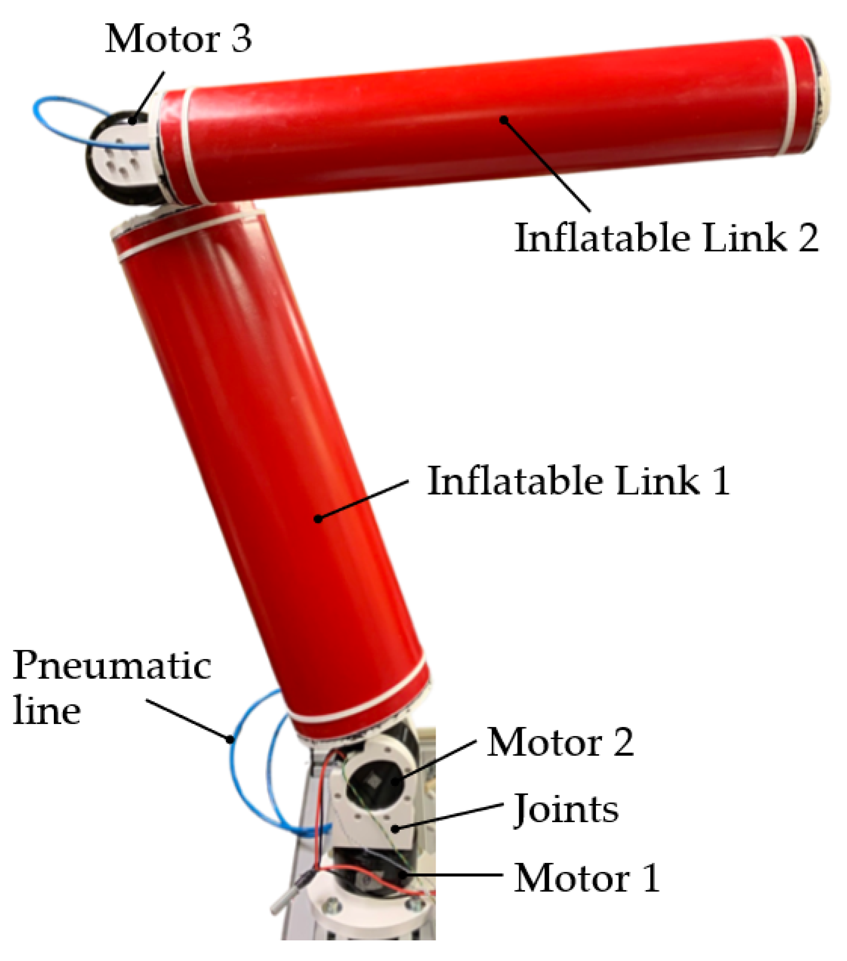
POPUP robot prototype, shown in
Figure 1, consists in a deployable robot with hybrid structure consisting of two inflatable links, three electric motors and rigid joints made by additive manufacturing.
The system includes a pneumatic line for the inflation of the links, an electronic circuit and built-in sensors. The EE presents a flange to easily permit the assembly a robotic wrist and/or a generic tool, increasing the DOF of the robot. Therefore, the robotic arm has 3 DOF, in its basic form, that can be extended depending on the application.
3.1. Mechanical Design
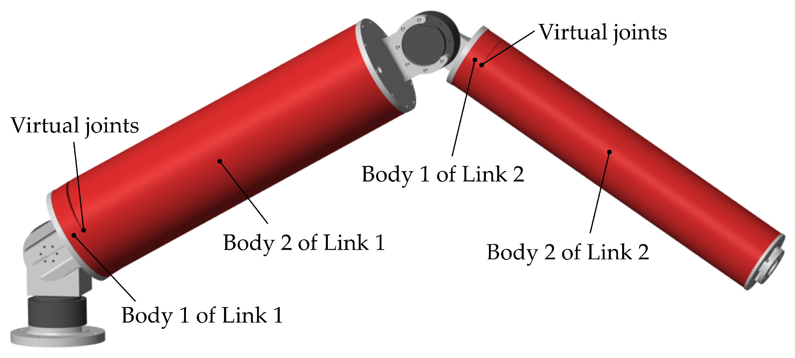
The robot links have cylindrical shape. The cylindrical surface is made by wounding a sheet of polymeric material. On the extremities two rigid rings are glued. The rings permit the links to be fixed through screws to the other joints, as shown in
Figure 2, allowing the possibility to add elements, e.g., sensors, inside the links during development stages. The motor joints represent the link tops and guarantee their isolation by using seals.
Both links have length
mm, link 1 has radius
mm and link 2 has radius
mm. Dimensions have been calculated using the wrinkling moment
formulation derived by Equation (
1) in order to reach a payload of 20 N, without showing wrinkles, at a pressure of 60 kPa. Since robot links have been successfully tested in the range 10–90 kPa, the prototype payload can reach 30 N. The motors of the joints are brushless, with 80:1 reduction ratio, having a radius of 49 mm, a thickness of 62 mm and, mass of about 0.8 kg each, rated torque of 48 Nm and peak torque of 144 Nm. Since the biggest contribution to the mass is due to the motors, the robot mass is under 4 kg. The mass account does not consider power supply generators or the tank, since not yet available as ad-hoc allocation.
3.2. Pneumatic Line and Deployment
The system architecture is shown in
Figure 3 where the pneumatic line and the electronic circuit are schematized.
A pneumatic line is responsible for the inflation and deflation of the links. Pressure supply is regulated by a reducing valve (RV) that provides pressure in the tested working range of 10–90 kPa. The links show acceptable performances with a pressure starting from 10 kPa. Internal pressure is measured through pressure transducers (PTs) mounted in proximity of the links. Compressed air can be provided by a pressurized tank or external pneumatic plant. Two valve groups, V1 and V2 for link 1 and 2 respectively, can provide pressure or deflate each the link separately. Valve groups consists of two digital valves: one connects the link with supply and the other one empties it. Valves are normally closed to avoid waste of energy, since they are activated only for inflation and deflation stages.
Links can be independently inflated and deflated to optimise the control of the deployment procedure. Once deployed and reached the working configuration, the pneumatic supply can be cut-off, although a by-pass should be considered to overcome air losses and maintaining constant the internal pressure. The tank, pressurized at 30 MPa and having a volume of 2 , allows us to inflate both links at a pressure of 50 kPa more than 10 times.
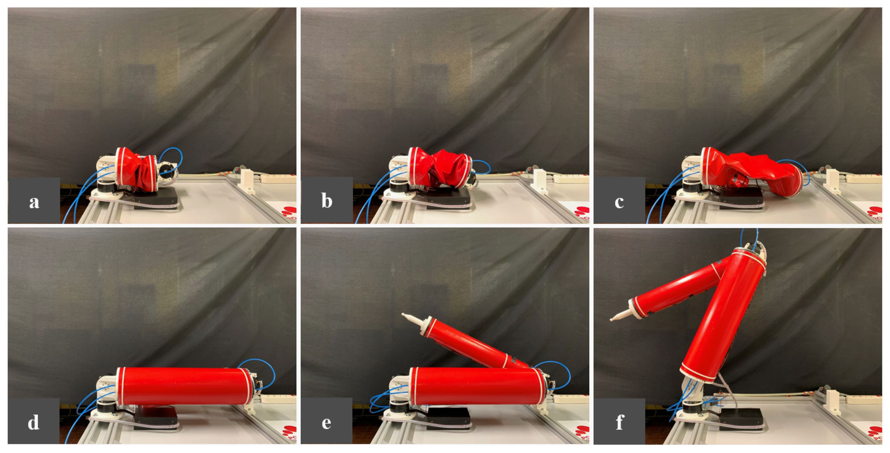
A demonstration of the deployment stage has been performed and shown in
Figure 4.
In the deflated configuration the robot could be potentially contained in a box, having a volume of
m against the operational working space of the extended robot of
m of radius if approximated with a sphere. The deployment stage includes different phases that facilitate the correct positioning and stability of the robot. For first, link 1 has been inflated and when the PT indicates it has reached the desired internal pressure, link 2 has been inflated to conclude the deployment. Built-in sensors are included to provide feedback about the success of the operation. In the current prototype, after the deflation, robot packing is assisted by user. A version with automatic wrapping is under development and described in [
44].
3.3. Sensors and Control Strategy Concept
Each link is equipped by sensors that provide an estimation of link deflections. Inertial measurement units (IMUs) are mounted on link extremities providing accelerations and absolute orientations by which the link deflections can be calculated. In addition, four flex sensors are positioned around the link cylinder region with higher static stress, i.e., the extremity closer to robot base in the kinematic chain. Each link is equipped by a dedicated board, called link board. Link boards acquire information from different transceivers and sensors, by I2C communication bus. A main board, responsible of the robot control, communicates with link boards and motors by CAN bus. A computer can be connected to the main board and manage robot tasks.
Sensor fusion and state estimation techniques, e.g., Kalman filter [
50], using information by sensors, can be employed to better estimate actual link state to properly control the robot, reducing inaccuracies due to the non-linearities of the system. Measured deformations are useful to obtain a better estimate of EE position through direct kinematics and to monitor the link condition and detect the wrinkling state. Strategies aiming to avoid wrinkling can be implemented considering acceleration limitation. In addition, vibrations can be reduced using link acceleration data in the control law: joint accelerations can be actively limited and/or properly set such as to compensate link accelerations.
Furthermore, a depth camera can be mounted on EE to identify the target and performing grasping operations with an accuracy that does not depend on the link state estimation: the camera can evaluate a relative positioning error between EE and target, producing a velocity set with respect to EE, allowing target following. More complex camera systems can be evaluated, e.g., additional cameras can be positioned on base to develop advanced logic for robot state estimation and for target identification, following and grasping.
5. Robot Modeling and Simulation
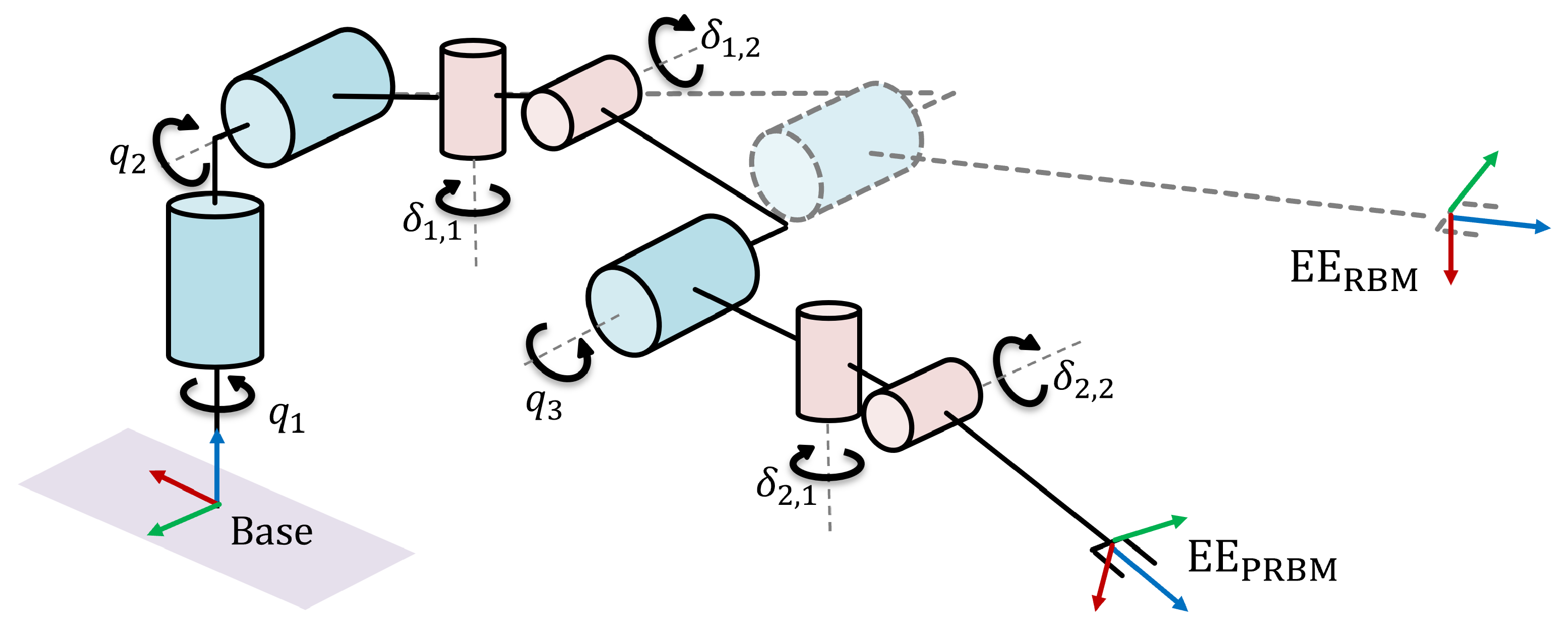
Extending the link model to evaluate the deflections along two orthogonal axes and neglecting the torsional deformations, the robot kinematic chain reaches 7 DOF. This description adds virtual uncontrolled joint variables, indicated as
, where
i is referred to the inflatable link number and
j to the orientation. In
Figure 8, the schemes of pseudo-rigid body model (PRBM) with flexible links and 7 DOF and the rigid body model (RBM) with 3 DOF are illustrated. Base frame, EE frame given the RBM and EE frame given the PRBM are represented. The Denavit–Hartenberg (D-H) parameters of the robot PRBM are shown in
Table 2. Listed parameters refer to physical and virtual links that appear in the definition of the robot with virtual joints: for instance, virtual link 1.2 connects virtual joint
with physical joint
.
A dynamic model of the robot with flexible links has been developed using the software Simscape Multibody™. In
Figure 9, the POPUP robot rendering with PRBM is shown. Dynamic parameters have been set using values based on experimental tests previously discussed. The link 1 stiffness coefficients has been calculated from link 2 values, according to the well-known formulation used for lumped-parameter methods
, with
E the material Young’s modulus,
the second moment of area and
l the length of the beam unity, that is,
in this specific case. Since link 1 differs from link 2 only for its cross-sectional area, the stiffness coefficients are scaled by the ratio of the second moments of area of the links. As a first approximation, the damping coefficient of link 1 has been estimated proportional to the stiffness coefficient. However, identification of robot dynamic parameters, executed using robot movements, is necessary to provide better accuracy to the system model. Hysteresis phenomena have been neglected. Alerts indicating a wrinkling condition have been implemented, monitoring virtual joint reaction torques.
A task, consisting in a target reaching, has been defined to underline main issues for the POPUP robot control. The target position
has been chosen to move the robot toward a more extended configuration, highlighting deflections due to the gravity. The robot control consists in a differential kinematics approach based on the Jacobian matrix
of the rigid body model, with 3 DOF, that relates joint and EE velocities. A suitable choise for the desired velocity
is:
where
is the relative distance between target position
and EE position
,
is the maximal initial acceleration and
is the maximal velocity. This approach allows us to have zero velocity at initial and final points, and it is suitable for other tasks, as following of a target in movement, e.g., space debris grasping. In
Figure 10 a scheme of the simulated task is shown: the robot, represented in the starting configuration
deg, has to reach the desired EE position
mm in base frame. Yellow and green spheres highlight EE position
and target position
respectively.
The following parameters have been set: payload of 2 kg, internal pressure kPa, maximal velocity and maximal acceleration of .
First simulation aims to underline differences in EE positioning between the flexible link robot and an equivalent rigid link robot, having same joint state. The virtual robot with flexible links has been controlled as a traditional rigid link robot, as shown in
Figure 11.
EE position
is calculated by direct kinematics
of RBM and expressed in base frame, function
represents Equation (
3),
is the Jacobian matrix of RBM in base frame,
is the desired joint velocity,
is the matrix gain,
is the reference input for POPUP system consisting in actuator, driver, and multi-body model,
,
and
are the motor joint position, velocity and acceleration respectively.
Results are shown in
Figure 12, where trajectories of RBM and PRBM are compared. Since the control algorithm uses RBM direct kinematics to calculate the EE position
, the equivalent robot with rigid link reaches correctly the target. Using PRBM, the trajectory is influenced by link deformations, as expected. In
Figure 13 the absolute difference of EE position between RBM and PRBM during the task is shown.
The PRBM shows an error that depends on the configuration and payload, due to gravity that bends the links. A difference of 6.6 mm for the EE position is exhibited in the starting configuration, corresponding to joint variables . The difference grows during the task up to 24.4 mm when the target is reached, since the final robot configuration is more extended, intensifying the deflections caused by payload.
The positioning error can be reduced with different strategies, as estimating the EE position with PRBM recurring to link sensor data. However this estimate depends on sensor accuracy, data fusion technique and simplification due to the adopted model.
Second simulation aims to validate a control strategy based on visual servoing (VS), with a camera mounted on the EE of the virtual robot with flexible link. Block scheme of robot control is shown in
Figure 14.
Using computer vision algorithms, the camera can identify the target position in EE frame
. Then, the desired velocity in EE frame
is calculated by Equation (
3), known
. Finally, using Jacobian matrix of RBM in EE frame
, the desired joint velocity
is calculated. Simulation provides exact feedback for target position
, validating the control algorithm independently from vision system errors.
Results are shown in
Figure 15. The robot with flexible links using PRBM, on which camera is virtually positioned, correctly reaches the target, demonstrating how this strategy is able to compensate link deflections minimizing the positioning error between target and EE. Trajectories calculated using PRBM and RBM with same joint state are plotted, underlining the difference in positioning between the virtual robot with flexible links and an equivalent robot with rigid links. With reference to
Figure 8, since Jacobian matrix of RBM is used,
frame is evaluated as actual EE frame. On the other hand, measured target position
is referred to
frame. Nonetheless, the control algorithm effectively compensates errors due to small deflections.
In
Figure 16 motor joint position values
are shown during the task, highlighting corrections provided by the camera-based algorithm with respect to a traditional robot control in order to precisely reach the target.
Results demonstrate the effectiveness of the presented control strategy based on visual servoing. Moreover, the algorithm potentially allows us to follow a target in movement. Since the desired position is correctly reached in the simulated environment providing exact feedback, the accuracy in positioning of POPUP depends on computer vision algorithms that have to be developed.
6. Conclusions
The prototype of POPUP, a deployable and inflatable robotic arm, has been proposed. The robot consists of two inflatable link and three rigid revolute joints actuated by electric motors. It can be stored in a relatively small box and deployed when required by inflation. The robot prototype has been described, underlining the design criteria and performance in terms of achievable payloads, in relation to the internal pressure. System architecture has been explained, focusing on sensors, electronics and pneumatic line, and proposing a control strategy based on sensor fusion techniques. A demonstration of deployment stage has been performed to highlight the packing ratio of the robotic arm prototype.
A pseudo-rigid body model has been used to describe the inflatable link behavior. Experimental tests has been performed to analyze the static and dynamic performance of the link, on varying the internal pressure. Results confirm the benefit of using wrinkling moment formula as design criteria, and validate the approximation of a linear static characteristics for loads under the wrinkling condition. However, the presence of hysteresis produces uncertainties on link characterization.
The robot kinematics has been modified introducing virtual joint variables and a multi-body model has been developed, according to experimental tests. Simulations have been performed to highlight differences in terms of positioning with a rigid link robot. Moreover, a control algorithm based on vision servoing, has been validated showing how errors due to link deflections can be compensated using a camera mounted on the end-effector.
Results suggest that link deflection and hysteresis are phenomena to be taken into account for development of robot control algorithms. The use of IMUs or generic accelerometers could allow the control law to reduce maximal accelerations and avoid wrinkling. The use of multiple sensors on robot links, as flex sensors and IMUs, could lead to the development of a better estimate of the link state and consequently of the robot state, monitoring the distance from theoretical wrinkling area and guaranteeing better performances.
Further works will focus on the implementation and validation of proposed control algorithm on the robot prototype. A comparison with models based on finite-element approach will be executed. The estimation of robot accuracy and precision will be carry out in relation to different sensor equipment. Control algorithms have to be improved including dynamic tuning of maximal acceleration, accounting link deflection state, defining a suitable state machine to manage the robot and developing computer vision algorithms for target identification and following.


