1. Introduction and State of the Art
In the modern component manufacturing industry, the use of CAx software is widespread, especially in automated series production. The advantages are an improved quality, reduced costs and shorter manufacturing time. In contrast, the design and construction of buildings are mostly individual and thus still require the execution of work on site, typically based on traditional manual processes using printed two-dimensional technical drawings. However, in recent years, digital process chains are also being developed in the construction of modern buildings using the Building Information Modeling (BIM) method [
1]. Analogous to the process in component manufacturing, one core method of BIM is the digital modeling of buildings. The modeling in BIM is based on parameterizable objects, functions and logics. Further advantages for the user include the creation of requirements and drawing plans, the possibility to calculate costs, simplified scheduling and the visualization of the building. At the end of the modeling process, manufacturing data can be generated from the digital models. These data sets might serve in the future as the basis for automating certain work processes and executing them by using different robots [
2,
3].
Notably, a major challenge in the design of automated construction systems is the extremely large volume of typical sites, which has to be covered by the automated construction solutions. Conventional robot arms fail, which is why special robot arms of large scale or mobile platform bases have been presented [
4]. Furthermore, the typical mass of construction elements is a challenge for those robot systems employing serial kinematic structures.
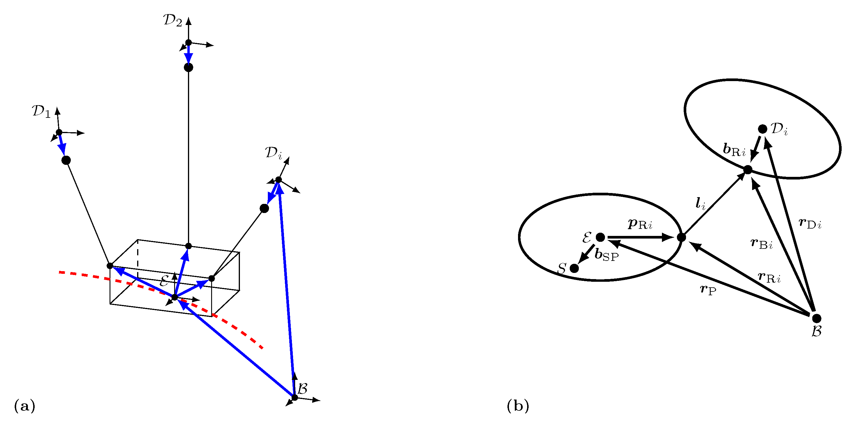
Alternatively, the use of multiple cables is an efficient approach to share payloads and to span large distances. Therefore, the concept of automated masonry using a cable-driven parallel robot (CDPR) has been presented recently [
5,
6]; see
Figure 1a. CDPRs are a special form of a parallel manipulator and thus share fundamental kinematical properties with hexapods. The workspace of the CDPR is spanned by a mobile frame which makes it attractive for construction processes. Within this workspace, the end effector of the robot can be freely positioned in all six degrees of freedom by individually changing the length and tension of the cables. The cables run from motor-controlled cable winches via guiding pulleys to anchor points on the end effector. The guiding pulleys are attached to the frame, either fixed or on movable mechanisms. The actual task of the cable robot for masonry works is then to pick up the bricks e.g., at an automated mortar system, and to place them in the defined poses according to BIM model data. Typically, this should be done in the shortest possible time. The CDPR has two properties that make it particularly suitable for this application. On the one hand, overactuation (e.g., using more actuated cables than the end effector’s number of Degrees-of-Freedom) can be used to enhance the stiffness of the system, which is crucial for outdoor applications. On the other hand, the movable masses are extremely low as these are essentially limited to the end-effector and the payload. Still, a CDPR has drawbacks, where the most obvious drawback is the high number of cables that may even run below the end effector level, which introduces a risk of collisions with already built structures or moving objects. This has to be handled, e.g., by vertically moving pulleys. Moreover, cables are unilateral constraints in general. This needs to be considered while path planning and control. In addition, the purchasing costs as well as the setup costs for the assembly and disassembly of the cable robot must be taken into account, when checking the economic feasibility [
7]. Still, a first prototype for automated masonry has been presented and technically validated [
8,
9] as shown in
Figure 1a, including an automated mortar station which delivers masonry units to the CDPR using a lifter. Notably, this prototype is designed for single-storey experiments and thus only the lower pulleys are actuated to move vertically. Due to their advantages, CDPR have been investigated also for other relevant construction processes such as 3D printing of concrete [
10,
11,
12,
13,
14] or curtain wall installation as demonstrated in the EU project, Hephaestus [
15].
In contrast, a multicopter or drone is a spatially unlimited applicable robotic system with comparatively low set-up costs. Since the beginning of their development, multicopters have been used to transport lightweight objects. A significant application example is a camera-carrying drone. In the film and advertising industry, drones are now predominantly used instead of helicopters because they offer much more versatile camera settings and are significantly less expensive. At large events, camera drones are used by the police and event organizers to monitor the event area and direct the stream of visitors. Another application scenario, although not yet as widespread, can be found in agriculture. Here, drones are used for example as an equipment carrier for pest control [
16]. In the construction industry, drones are primarily used for land surveying, documenting the progress of construction work or assessing damage of hard-to-reach places or areas [
17,
18,
19]. Additionally, they are used for active monitoring of construction sites to achieve an increase in construction site safety. For an overview, see [
20]. All previously mentioned use cases have in common that the payload of the drone is comparatively small.
Over the years, however, the payload for drones increased continuously, so that, nowadays, heavy-lift drones with a maximum payload of up to
can be purchased. The reason for this are, among other things, increasingly better lithium-ion batteries, which enable the use of more powerful motors [
21]. Due to these developments, drones are thus becoming increasingly interesting for the transportation of heavy loads or for the use in internal logistics [
22]. Research in the field of alternative energy sources, such as the use of a fuel cell, may increase the operating time in the future [
23]. A multicopter might be equipped with an end effector that is able to pick up a payload. Essentially, three different approaches are pursued; see [
24]. In the simplest case, the end effector is firmly connected to the drone [
25,
26,
27,
28]. However, when using underactuated drones, this method has the disadvantage that the payload cannot be fully oriented. One way to overcome the underactuation is to use a rigidly mounted end effector in combination with a full- or overactuated multicopter [
29]. A different approach discussed in [
30,
31] is the use of drones with robotics arms. This second approach also allows the independent movement of the payload in all six degrees-of-freedom. The approaches described so far are particularly suitable for the transport and/or manipulation of lightweight objects.
One disadvantage, however, is that the payload is usually located very close to the drone. This might be an issue in specific applications (e.g., in cluttered environments). Therefore, another frequently investigated use case is the transport of a payload that is connected to a drone via a cable. This allows the adjustment of the distance between the drone and the payload almost arbitrarily. As a major advantage, by using multiple, cooperating drones connected to a common payload using cables, the maximum payload weight can be drastically increased and the maneuverability can be enhanced. In the past, drone cooperation has already been investigated repeatedly. In [
32], the transport of a payload, which is still considered as a point mass, is investigated using two drones. However, this does not increase the controllability and, furthermore, the drones have to be far enough apart. If the distance of the drones is increased, the cable forces increase as well since the system is closer to a singularity of the second kind. The transport of a rigid beam using two quadrocopters is demonstrated in [
33]. With the use of three or more drones, the payload is kinematically underconstrained [
34] but statically determined with the help of gravity. Moreover, it can be fully controlled, as the three drones in total have more controllable degrees of freedom than the end effector. As examples, flight maneuvers with three drones are presented in [
35,
36,
37]. When using three or more drones, there is also the possibility to reconfigure them in space without moving the payload. With these maneuvers in null space, the properties of the system can be influenced. This fact and the relation to cable robots is considered in [
38]. The goal of planning an optimal trajectory in terms of the cable angles and energy efficiency is considered in [
39]. Path planning under external disturbances is shown in [
40]. Planning a trajectory for the specific task of flying through a window is the subject of the work [
41]. In addition, [
42] deals with highly dynamic trajectories. The procedure of lifting the payload is analyzed in [
43,
44].
In the scope of this paper, another possible scenario would be using cooperating drones on large construction sites to handle internal logistics or to do simple construction tasks, such as the automated masonry already mentioned, see
Figure 1b. Unlike cable robots, drones are not locally bound. Furthermore, the space and infrastructure requirements on the construction site are easy to provide.
Accordingly, while both systems use cables to share the load of high payloads, they still have inherent technological differences, leading to differing characteristics when used for automated masonry. As for this application, both systems have only been tested in very early technological stages, but might be very promising to be developed within future research projects, it is reasonable to create approaches to evaluate and compare their potential performances in automated masonry using simulation tools. Thus, this contribution aims at comparing the two presented cable-based systems in predefined scenarios using numerical model-based simulations. Due to the model-based approach, the physical models for both the drone system and the cable robot need to be derived in detail. Based on a software framework, the two robotic systems are evaluated, defining two different scenarios. The first scenario demonstrates the applicability and capabilities of the optimizer approach. The second scenario is used to compare the two systems in terms of several performance indices such as required construction time and energy requirements.
The paper is structured as follows: In
Section 2, the methodical approach and the used optimization framework are presented.
Section 3 introduces the cost functions used for the path planning algorithm. The approach is then demonstrated in
Section 4 to optimize trajectories for a cable robot and a system of cooperating drones. The optimization results and the different characteristics of both systems are discussed. The paper is summarized in
Section 5.
4. Discussion of the Optimization Results
The following scenarios under consideration deal with the automatic construction of a building consisting of 1720 calcium silicate units. These mainly include calcium silicate masonry units of the type 6DF [
62,
63], as well as flat lintels and masonry units to compensate height differences. Note that, for all units, the optimization has ended penalty-free for both systems, i.e., all undesired events could be avoided and all final optimization runs terminated with valid trajectories.
In the first scenario, a drone system with three quadrocopters as shown in
Figure 1b is used to transport the payload past some already erected buildings to the actual construction site. In this case, the optimizer is forced to plan a path which avoids collisions. The scenario is used to verify the functioning of the implemented algorithms. The drone system used in this first scenario has the parameters listed in
Table 2. Notably, with the given drone system, the platform is kinematically underconstrained [
34], which means that the system might oscillate in case of disturbances. Applicable control approaches are subject to future work, where e.g., flatness-based approaches are promising [
64].
To identify and compare the advantages and disadvantages of each robotic system, the second scenario deals with the optimization of the entire construction process for all 1720 masonry units for this drone system and the cable robot presented in
Figure 1a. For the optimization process, all trajectories are employed as given in
Table 1. Note that the mass of the platform is subject to instantaneous changes after gripping the masonry unit between trajectories 3 and 4 and after placing the masonry unit between trajectories 10 and 11. This inevitably leads to discontinuities, e.g., in cable forces or propeller speeds. Such discontinuities might as well lead to theoretically infinite accelerations, e.g., at the motors of the drones. However, since the simulation framework is using an open loop physical model and calculates each trajectory independently, this does not lead to problems within the simulation. The effects of this short time period were assumed to be negligible in terms of energy consumption and overall construction time. Thus, a modeling of such effects was not included within this work. Future work includes the modeling of the contact forces when gripping or releasing a masonry unit.
The cable robot’s parameters are given in [
48]. The most important ones are
The end effectors of both systems differ in their ability to rotate the masonry unit. In the case of the drone system, the rotation comes from the absolute positioning of the drones. In comparison, the end effector of the cable robot can actively rotate a masonry unit. For this reason, the end effector of the drone system can be built much lighter since the rotation unit, using a powerful electric motor, heavy bearings and an extra frame [
9], is omitted. Moreover, the frame of the end effector for the drone can be built using more lightweight elements since the expected cable forces are lower in comparison to the CDPR and the cables are not tensed against each other. Additionally, five cable attachment points and five cable force sensors are not needed. Therefore, it is assumed that the weight
of the end effector of the cable robot can be reduced to
for the drone system.
Notably, in both scenarios, the 6th trajectory—which is basically the motion across the site—of the 1000th masonry unit is discussed in more detail with its starting position
A and its target position
B. Apart from the lateral movement from its starting position
to its target position
, the masonry unit is additionally rotated by
around the
-axis. Hereby, the target position and the rotation angle result from the masonry laying plan. Note that cable angles
are used for evaluation. These angles are defined as the Cardan angles analog to
Section 3.2, such that the initial unit cable vector
is mapped to
.
First scenario: For the first scenario, the 6th trajectory starts at point A with
and ends at point B with
passing two additional knots
and
. These knots with their vectors
and
are optimized as well as the platform’s velocity and acceleration at these points. The relative position of the drones to each other is influenced by the definition of the vector
in Equation (
18). The choice
results in solutions where the drones are as close as possible to an angle of
around the
-axis to each other. The scalar value
can be used to adjust the spreading between the drones, since the force
calculated with Equation (
18) is the one that has the smallest distance to
with respect to Euclidean norm. Therefore, an increasing value
results in a greater distance between the drones.
The optimization is done using the introduced Particle Swarm Optimizer of MATLAB
® with its default settings [
65] and the parameters of the cost functions as shown in
Table 3.
Note that the comparatively high value of
results from the power of three in Equation (
24) and the need for small drone angles
and
to meet the assumption
.
Figure 5 shows the optimization result for trajectories 4 to 10.
As desired, the optimized trajectories avoid all obstacles.
For the 6th trajectory, the transition time is reduced by the optimizer from initially
to
. The platform is with
in perfect rest at the start and target position. The optimizer changed the initial position, velocity and acceleration vectors of the platform at the additional knot S1 and S2 to the vectors given in
Table 4. To obtain a better impression of the actual platform and drone speeds, the calculated position of the drone’s cable attachment points are additionally highlighted at constant time intervals. For the rotation of the masonry unit, the whole end effector has to be rotated. Therefore, the drones must change their absolute position to each other in a coordinated manner.
This fact can be seen in
Figure 5 by the intersections of their flight paths. Moreover, the relative alignment of the drones at approximately
is clearly visible. After the optimization, the spreading factor has the value
. This value is mainly affected by two cost functions. The costs of the rotor speeds
are increasing as
becomes larger and, thus, the optimizer tries to achieve the smallest possible
. The cost function
has the opposite effect and increases when
decreases, as the AABBs get closer. Thus,
can be influenced by the weights of
and
.
The associated cable and drone angles are shown in
Figure 6a–c.
As an example, the curves for the drone D2 are considered in more detail at the start and target position. From Equation (
48), it follows that at the starting point, the cable vector of this drone lies within a plane parallel to the
-plane of the inertial frame, pointing in positive
y- and
z-direction. This requires a single rotation around the
x-axis of the inertial frame with
and
. To achieve a stable system behavior while hovering, the drone must be tilted less than the cable and, therefore,
must hold. Both conditions are confirmed by the angles calculated by the optimizer. At the target position, the drone D2 is oriented in such way that the cable lies within a plane parallel to the
-plane of the inertial frame, pointing in positive
x- and
z-direction. This requires a single rotation with
and
. Furthermore,
must hold. These considerations are also confirmed by the results in
Figure 6b. The same procedure can be used to check the other cable and drone angles at the start and target positions. During the trajectory, maximum angles of
occur. The differences between the cable and drone angles are
and
. The results of the required rotor speeds are shown in the
Figure 6d–f separately for each drone. It can be seen that, due to the arrangement of the cables at the end effector, all drones must carry the same load in stationary case. To reach
and
, the rotor speeds of drone D2 must satisfy the conditions
and
. This is the only possibility to generate a counter reaction torque to the constraint torque applied by the cable. For the given trajectory, only small differences in rotor speed of about
from the hovering speed are necessary. The hovering speed can be derived for the stationary case from Equation (
16), which simplifies to
For the 1000th masonry unit the hovering speed is . The curves of both the cable and drone angles as well as the rotor speeds have the desired smooth curve. In total, the optimization result of scenario 1 shows that the path planning framework works as expected. This means that a penalty-free solution for a complex maneuver was found.
Second scenario: The second scenario is a comparison between the drone system already presented and a cable robot. The cable robot mainly consists of a base frame to which pulleys are attached. The cables enter the actual workspace via pulleys. The platform is moved by changing the length or tension, respectively, of each of the
cables in a coordinated manner [
66]. For the drone system, the movement of the platform results from the movement of each individual drone for constant cable lengths. The masonry units are fed to the construction area via an automated mortar system. Since the mortar system is also responsible for applying the mortar in addition to feeding the masonry units, it is also used for the drone system. For a comparison of both robotic systems, the trajectories for all 1720 masonry units of the first floor are optimized and compared in terms of time required and energy used. Due to the natural boundaries drawn by the workspace of the cable robot frame, the danger of a personal injury is little. Since it can be assumed that there are no obstacles in the workspace other than the masonry units already placed, the masonry units are transferred from the start to the target position using straight trajectories. As this simplifies numerous operations, and to maintain comparability, this trajectory shape is also used for the drone system. Accordingly, for the cable robot, the only optimization parameter is the transition time, which is why a gradient-based optimization method is suitable. For this purpose, the optimizer fmincon of MATLAB
® is used with its default settings [
67]. The parameters for the cost function are listed in
Table 5.
Although a lower cable force limit of
seems to be excessive, it is well chosen from practical experience (and thus also include a practically identified safety margin for control purposes). The drone system has the same characteristic as in the first scenario. In addition to the actual transition time
, the spreading factor
is also optimized. In this case, as in scenario 1, a particle swarm optimization is preferred. The parameters of the cost functions are the same as in
Table 3, with the exception that
for
.
For both systems, the optimization results in the desired straight trajectories. Based on the AABBs for the end effector and the masonry unit, the result shows the different rotation methods for the masonry unit around the platform’s -axis. For the cable robot, it can be seen that the end effector maintains its orientation throughout the transportation while the masonry unit rotates. For the drone system, however, the rotation of the masonry unit is the same as that of the end effector to which the masonry unit is attached. For both systems, the expected change in the size of the AABBs can be seen during the rotation. Furthermore it is obvious that the cables of the cable robot are blocking relevant volumes within workspace during the motion. This increases the risk of cable collisions, to be avoided by the optimizer. For the scenario at hand, the lower pulleys have already reached a certain height. Note that the pulleys are lifted with a rising building between two masonry units of different layers. Moreover, the transfer position of the mortar system is lifted accordingly. In contrast, the cables of the drone system are always above the end effector. Hence, cable collisions with an obstacle are almost impossible if a certain laying plan is maintained.
The resulting cable forces are presented for the cable robot in
Figure 9. Analogously, the rotor speeds for the drone system are shown in
Figure 10d–f.
For the cable robot, the highest calculated cable forces are below . This means that the optimizer was not able to accelerate the trajectory any further due to the defined penalties, although the cable robot still has cable force reserves. For both systems, the curves show a smooth course, with the exception of the transition during gripping or placing the masonry unit. The force of gravity of the platform varies in dependence of the actual masonry unit mass. For the cable robot this varies between and and for the drone system between and . Due to the movement of the drones along with the platform, the cable forces are only slightly more than one-third of each. In the case of the cable robot, the cables often have a unsuitable flat angle at the platform due to the cable pulleys fixed at the frame. As a result, the net cable forces of the cable robot to carry the platform tend to be in the lower kN range and are thus many times larger than the cable forces of the drone system. Another reason for the high cable forces is that the lower cables additionally pull the platform downwards. Therefore, it follows that the cables of the drone system are subjected to much less stress. On the other hand, however, each drone of the drone system has to carry its own weight on top of the platform’s weight. Depending on the platform’s mass, this results in the hovering speeds which are, compared to the theoretical speed for applying the force of gravity, slightly increased. The deviation depends on the spreading factor . Using the lift coefficient, the theoretically required force per drone of to can be calculated. The significantly better ratio of the force needed to carry the platform is solely due to the cable angles at the platform.
Despite the significantly larger necessary cable forces, the cable robot is more efficient due to its drive concept. With the given quantities of the cable robot, the resulting force per watt of applied power can be calculated for the stationary case. Using Equations (
26)–(
29) leads to the relation
From the manufacturer’s data sheet for the drive unit of the drone system the same relationship can be derived with
Common to both systems is that the ratio decreases with an increasing force. A comparison of the ratios
and
is done for the initial position of the 1000th masonry unit, which can be seen in
Figure 9 and
Figure 10. For the cable force
, one can calculate
, which is over 329 times more effective than the ratio of
for the total thrust of
of the drone D2. Another advantage of the cable robot is its ability to recuperate energy when lowering or decelerating the masonry unit. Recuperation of stored kinetic or potential energy is currently not realistic in the case of the drone system.
Integral comparison and conclusion: From the optimization results, it follows that the overall construction time for all 1720 masonry units is for the cable robot and in the case of the drone system. Hence, the drone system requires approximately more time, which corresponds to a value of over . With a total of , a lot of time is needed for the measurement processes during trajectories 1 and 8. Therefore, the actual time for moving the platform from A to B is comparatively small compared to the waiting and measurement time. Especially for the drone system, this has a very negative effect due to the high energy demand. The drone system with requires more than 44 times as much energy as the cable robot with . This fact is mainly due to the bad ratio of applied power to the resulting lift force. In practice, this results in 186 battery changes for each drone during construction. Assuming that two minutes are needed to change the batteries of all three drones, this task would add another to the construction time. Looking at the recuperated energy of the cable robot, the amount of energy over all masonry units is , which is about . Accordingly, the recuperation capability contributes significantly to the low energy consumption of the cable robot.
Another disadvantage of the drone system is its significantly more complex positioning. While the positioning of the end effector in the case of the cable robot can be directly determined with a high accuracy via the cable lengths, complex methods must be applied to determine the position of the drone system. Conceivable options are, for instance, the usage of satellite navigation with the application of real-time kinematic positioning or an optical tracking system. In addition, the platform with only three cables is statically indeterminate in the case of the drone system, which is why it can always be stimulated to make undesired movements by disturbances such as wind. In contrast, the platform of the cable robot with eight cables is even statically overdetermined. The drone system, however, has its advantages when it comes to flexibility, beginning with its much faster setup time. Moreover the drone system has great advantages whenever spatially flexible transports over long distances are required, as in the application of scenario 1. Here, the cable robot is not an alternative. The same applies to very large buildings. Here, the frame of the cable robot, the mortar system and the pulleys would have to be constantly readjusted. Due to the limited workspace and the unsuitable cable angles, it is even important for the cable robot that the masonry is centered in the construction space of the cable robot (which might have a climbing frame to support e.g., high rise buildings). In conclusion, it can be said that both systems are suitable for transporting heavy loads, whereas the cable robot might as well transport masonry units significantly heavier than in this scenario. In conclusion, due to the discussed differences in their characteristics, their fields of application also differ widely. While the cable robot is predestined for the movement of very heavy loads within a defined and limited workspace with a very high accuracy and/or over a long time period, a drone system has its advantages above all when the transportation has to take place over longer distances for a limited period of time.


