Digital-Twin-Based Flexibility Wires of a Circular Connector Automatic Disassembly Process
Abstract
:1. Introduction
2. Background
3. Separate Module
3.1. Design of the Separate Jig
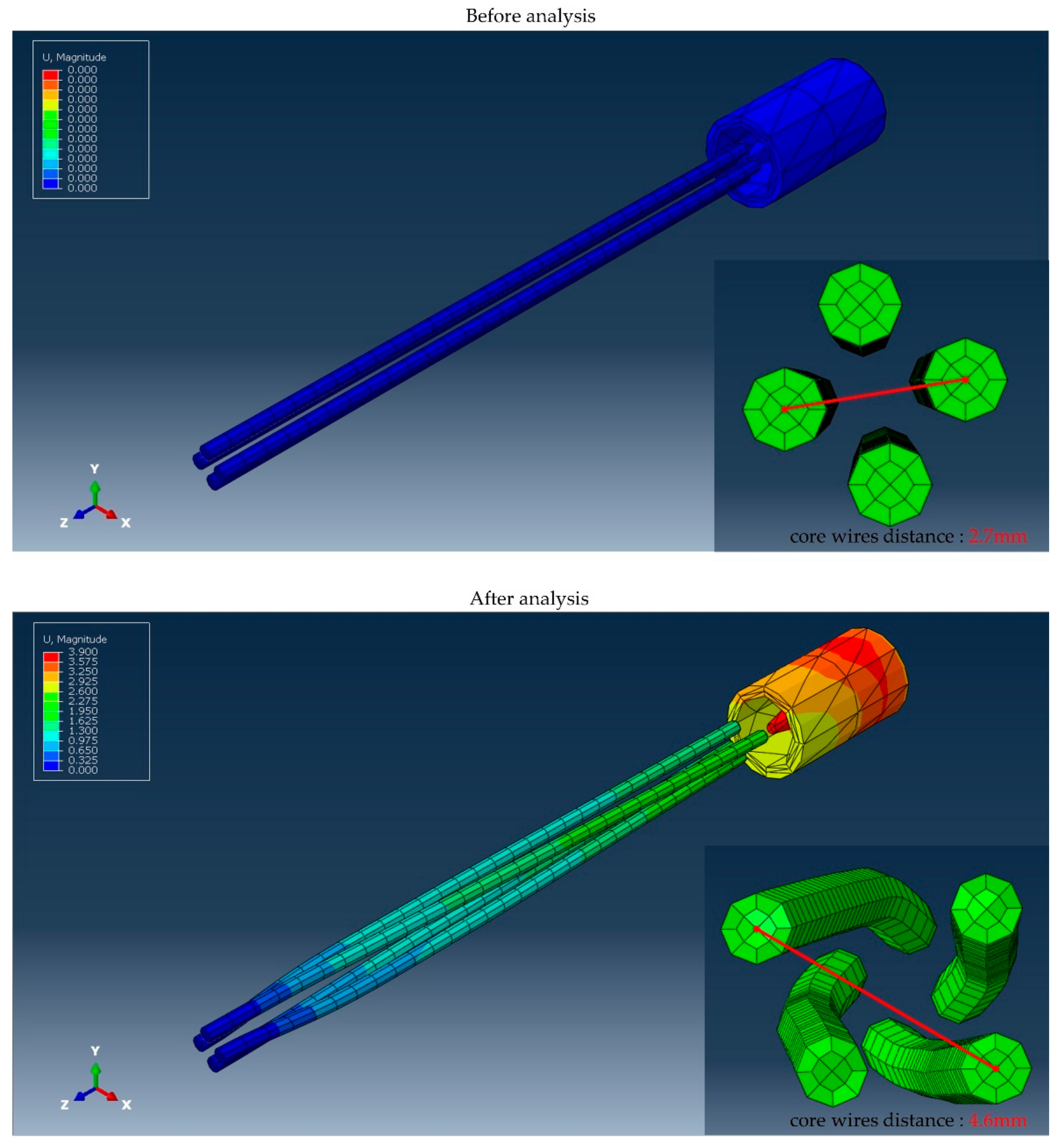
3.2. Simulation of Wire with Separate Jig
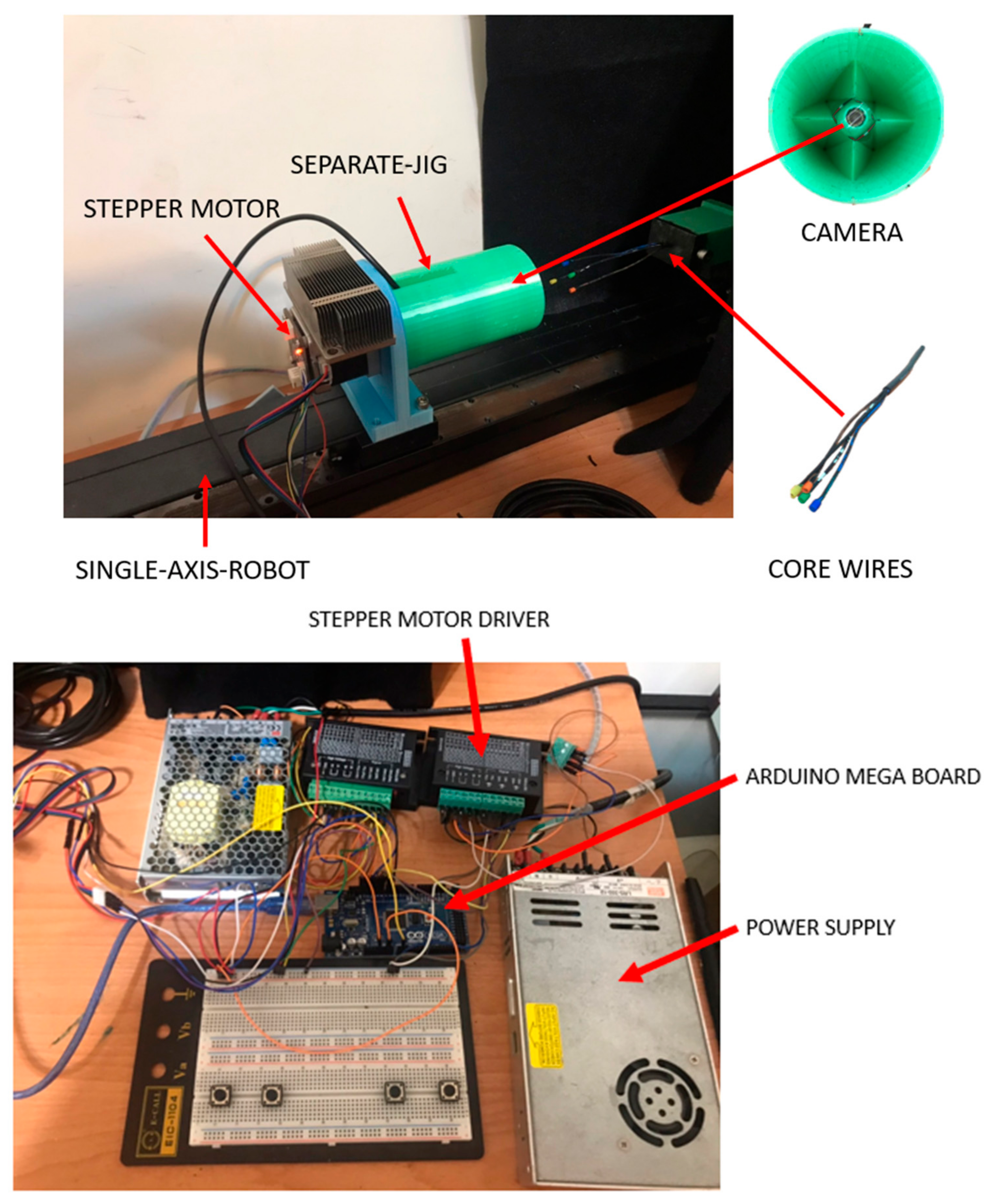
3.3. Mechanism Design
- Single-axis-robot: NEMA 23HS7430
- Stepper motor: NEMA 17 with encoder
- Camera: USB Endoscope Inspection Camera
- Power supply: MEANWELL-LRS-350-12
- Arduino mega board: MEGA2560 R3
- Stepper motor driver: TB6600 stepper motor driver.
3.4. Control Scheme of the Wires Separating
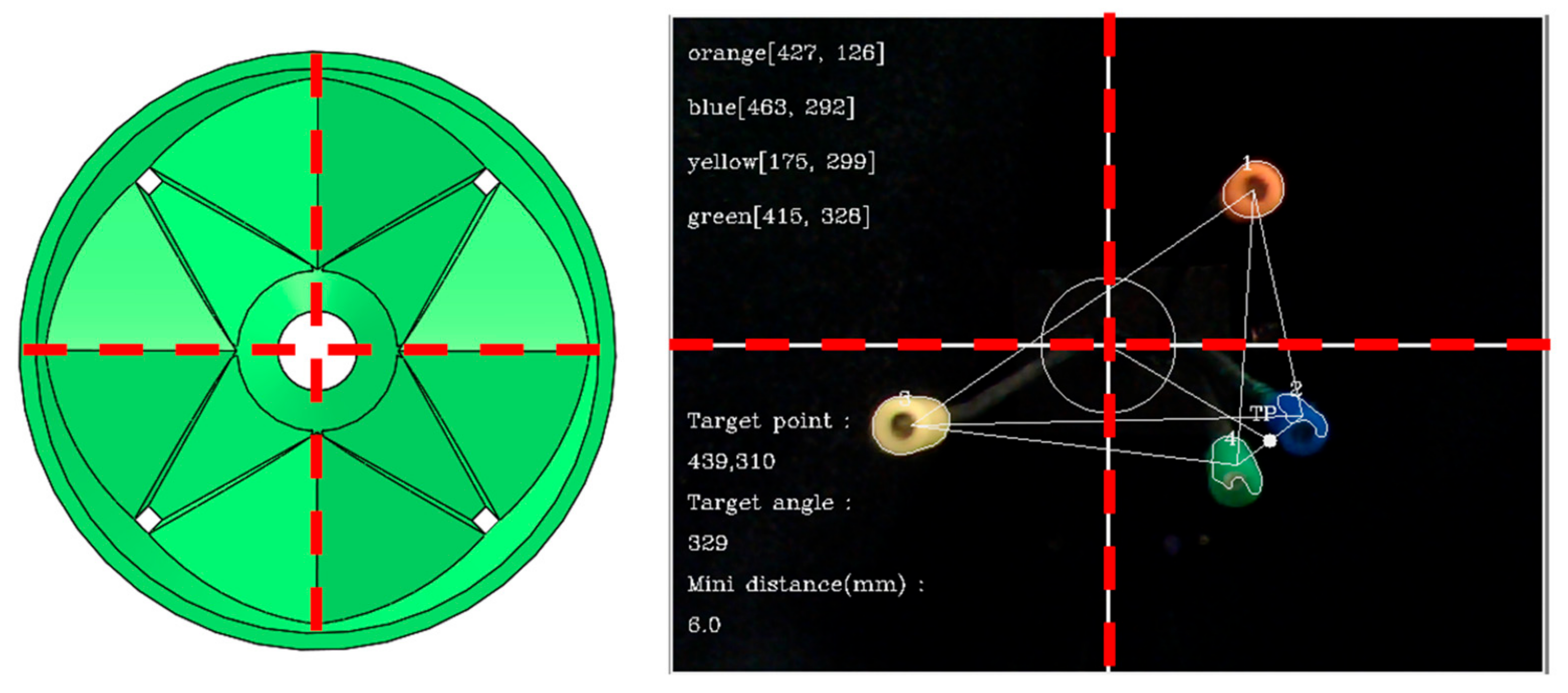
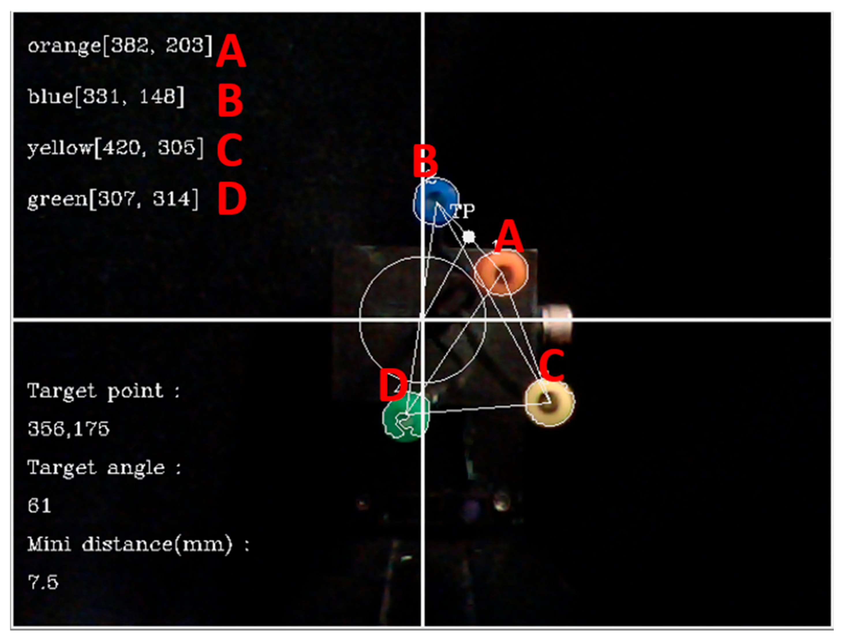
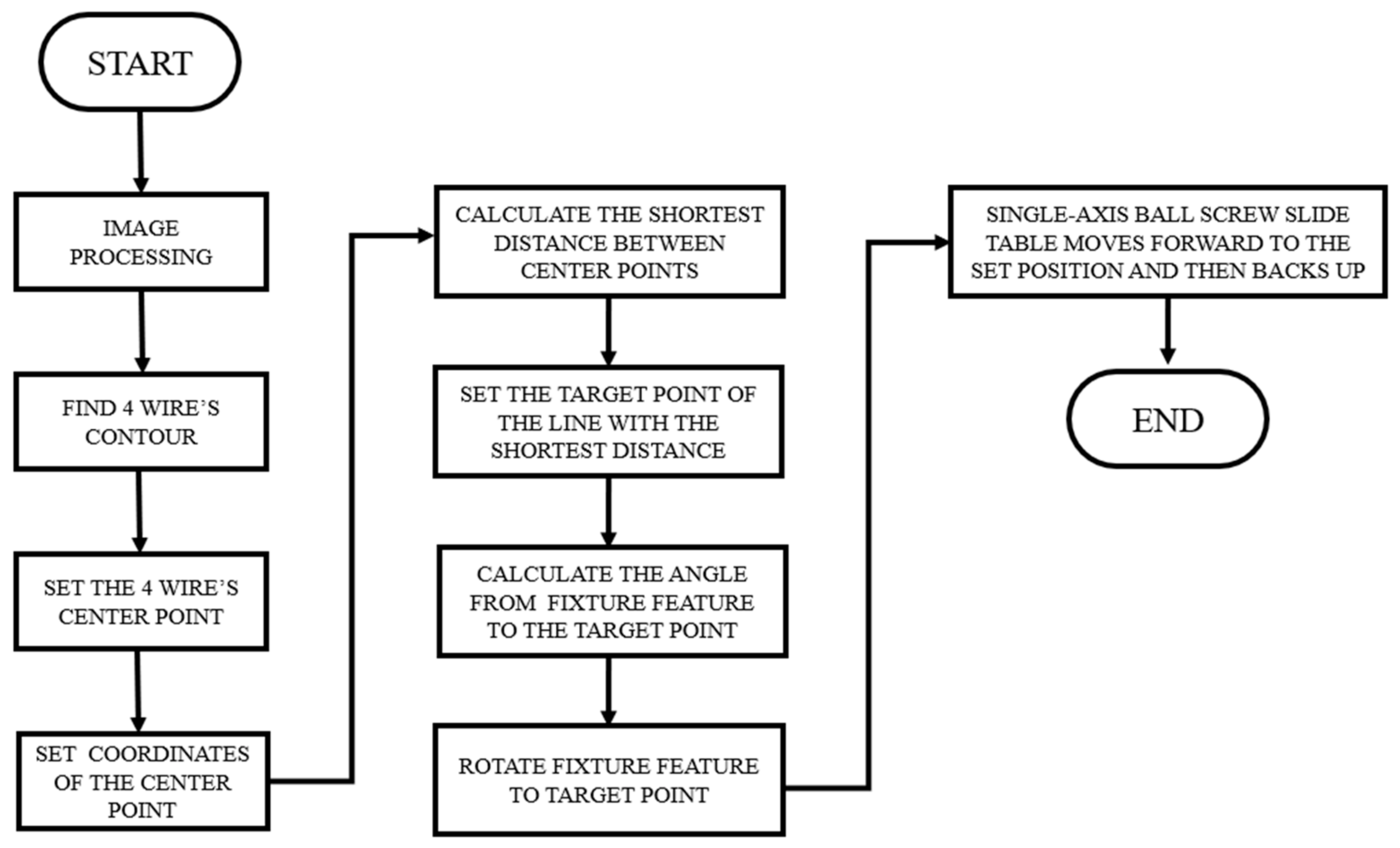
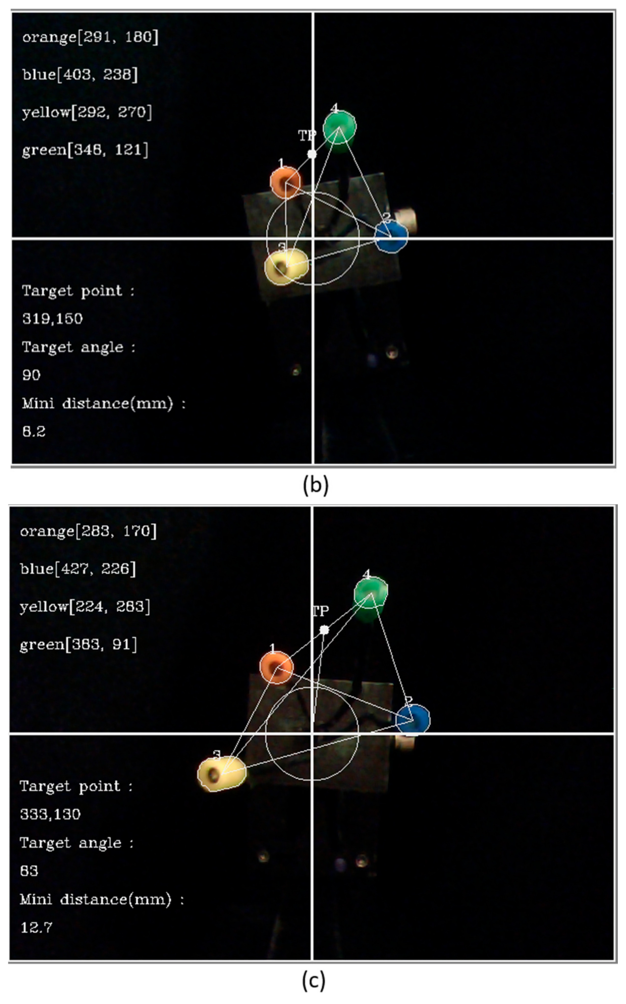
- In the first step, four coordinates, A, B, C, and D, were obtained by image processing, as shown in Figure 12.
- In the second step, six lines could be drawn between the four coordinates, Dab, Dac, Dad, Dbc, Dbd, and Dcd, as shown in Figure 13, and the distance between the lines could be found by Equation (2).
- In the third step, according to the calculated length, the shortest line was found to be the smallest distance between the four core wires.
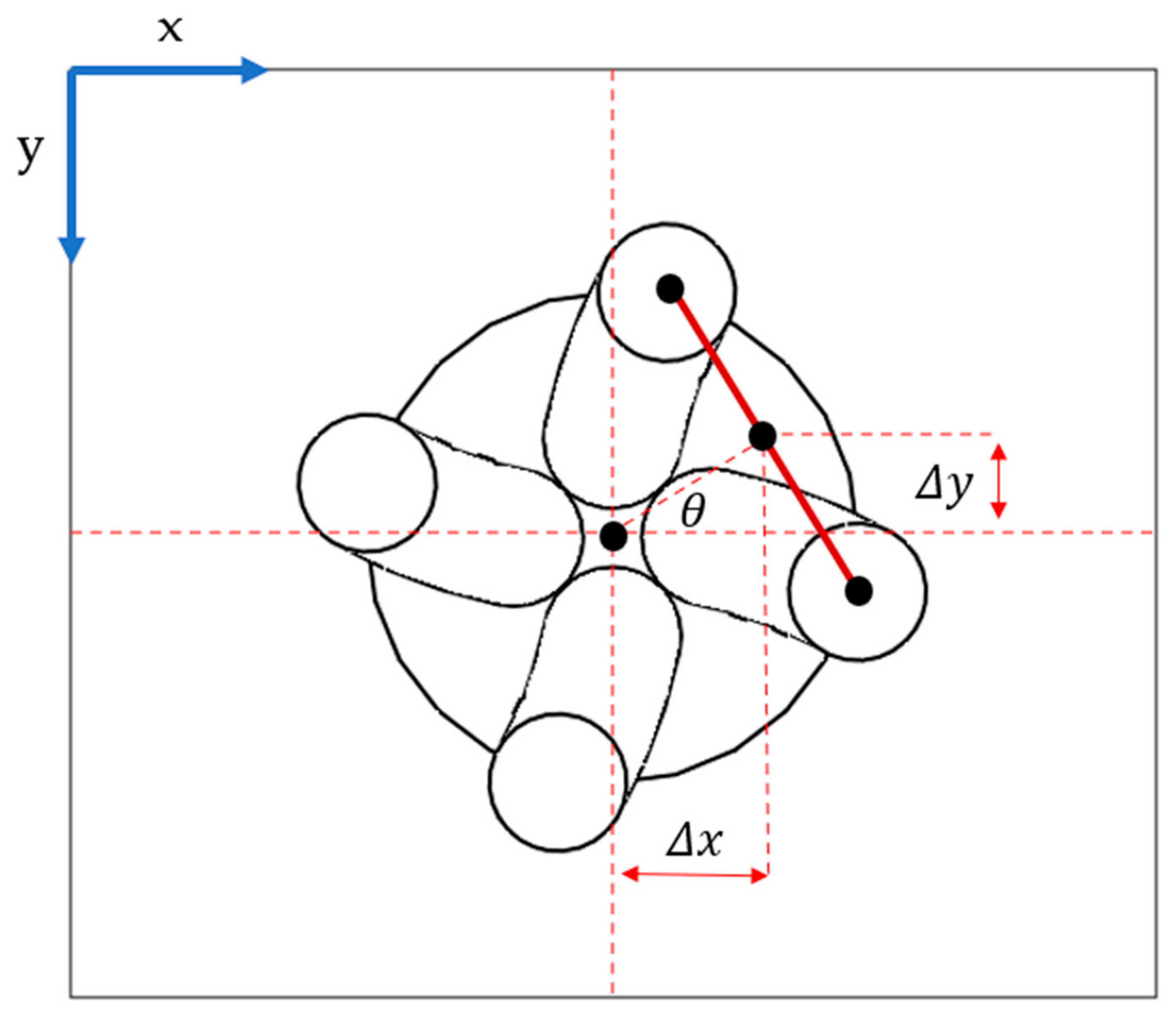
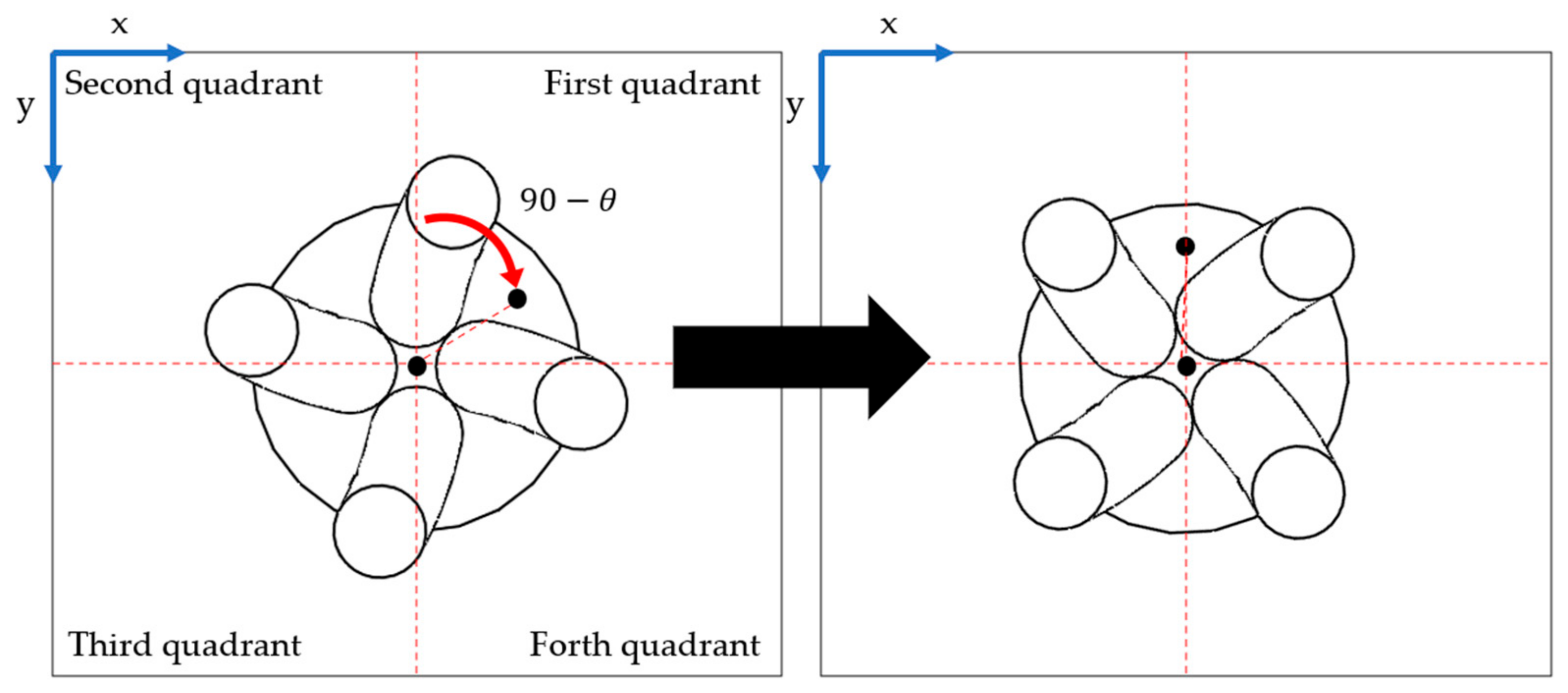
- The fifth step was to calculate the angle between the target point and the separate feature using Equation (4), as shown in Figure 15.
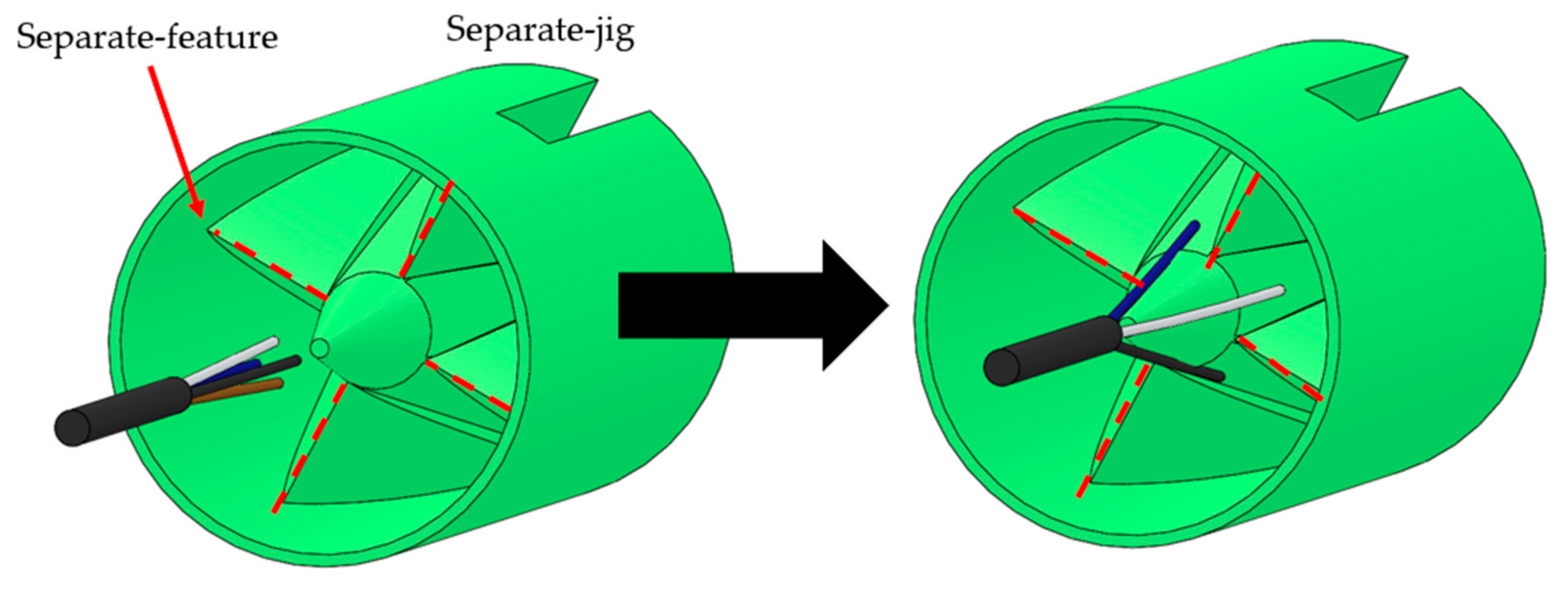
- Final step: Once the separate feature is aligned between the two shortest lines, the separate jig can separate the core wire forward, as shown in Figure 17.
4. Experiment
4.1. Experimental Design
4.2. Wire Separating Process
5. Experimental Results
- Experimental goal: The distance between the four core wires is greater than 9 mm, which allows the robot fingers to operate on the welding platform.
- Experimental success: Rotate the fixture feature to the target point. The distance between the four core wires is greater than 9 mm.
- Experimental failure: During automatic operation, the core wire is bent out of the camera range by the separation jig.
- If part of the wire is staggered, the wire can easily spring back because of its flexibility, and the wire can be separated after the second job.
- When working, there is an opportunity to divide the other cores into the same quadrant; therefore, when the targets are separated, the distance between the other cores decreases slightly. In most cases, it can be performed with a second or more passes.
6. Conclusions
Author Contributions
Funding
Data Availability Statement
Acknowledgments
Conflicts of Interest
References
- Global Connector Market (2021 Edition): Analysis by Product, End User, by Region, by Country Market Insights and Forecast with Impact of COVID-19 (2021–2026); ReportLinker: Lyon, France, 2021.
- Jiang, X.; Koo, K.M.; Kikuchi, K.; Konno, A.; Uchiyama, M. Robotized Assembly of a Wire Harness in a Car Production Line. Adv. Robot. 2011, 25, 473–489. [Google Scholar] [CrossRef]
- Huang, J.; Fukuda, T.; Matsuno, T. Model-Based Intelligent Fault Detection and Diagnosis for Mating Electric Connectors in Robotic Wiring Harness Assembly Systems. IEEE/ASME Trans. Mechatron. 2008, 13, 86–94. [Google Scholar] [CrossRef]
- Busia, M.; Cirillob, A.; de Gregorioc, D.; Indovinia, M.; de Mariab, G.; Melchiorric, C.; Nataleb, C.; Pallic, G.; Pirozzib, S. The WIRES experiment: Tools and strategies for robotized switchgear cabling. Procedia Manuf. 2017, 11, 355–363. [Google Scholar] [CrossRef]
- Li, X.; Cheah, C.C. Global task-space adaptive control of robot. Automatica 2013, 49, 58–69. [Google Scholar] [CrossRef]
- Cheah, C.C.; Li, X. Task-Space Sensory Feedback Control of Robot Manipulators; Springer: Berlin/Heidelberg, Germany, 2015. [Google Scholar]
- Slotine, J.-J.E.; Weiping, L. Adaptive manipulator control: A case study. IEEE Trans. Autom. Control 1988, 33, 995–1003. [Google Scholar] [CrossRef]
- Niemeyer, G.; Slotine, J.-J.E. Performance in adaptive manipulator control. Int. J. Robot. Res. 1991, 10, 149–161. [Google Scholar] [CrossRef]
- Takegaki, M.; Arimoto, S. A new feedback method for dynamic control of manipulators. J. Dyn. Syst. Meas. Control 1981, 103, 119–125. [Google Scholar] [CrossRef] [Green Version]
- Sanchez, J.; Corrales, J.-A.; Bouzgarrou, B.-C.; Mezouar, Y. Robotic Manipulation and Sensing of Deformable Objects in Domestic and Industrial Applications: A Survey. Int. J. Robot. Res. 2018, 37, 688–716. [Google Scholar] [CrossRef] [Green Version]
- Li, X.; Su, X.; Liu, Y.-H. Vision based robotic manipulation of flexible PCBs. IEEE/ASME Trans. Mechatron. 2018, 23, 2739–2749. [Google Scholar] [CrossRef]
- Li, X.; Su, X.; Gao, Y.; Liu, Y.H. Vision-based robotic grasping and manipulation of USB wires. In Proceedings of the 2018 IEEE International Conference on Robotics and Automation (ICRA), Brisbane, Australia, 21–25 May 2018; pp. 3482–3487. [Google Scholar]
- Gao, Y.; Chen, Z.; Fang, M.; Lin, J.; Liu, Y.H. Vision-based grasping and manipulation of flexible USB wires. In Proceedings of the 2019 IEEE International Conference on Robotics and Biomimetics (ROBIO), Dali, China, 6–8 December 2019; pp. 1083–1088. [Google Scholar]
- Bahubalendruni, M.V.A.R.; Varupala, V.P. Disassembly Sequence Planning for Safe Disposal of End-of-Life Waste Electric and Electronic Equipment. Natl. Acad. Sci. Lett. 2020, 44, 243–247. [Google Scholar] [CrossRef]
- Negri, E.; Fumagalli, L.; Macchi, M. A Review of the Roles of Digital Twin in CPS-based Production Systems. Procedia Manuf. 2017, 11, 939–948. [Google Scholar] [CrossRef]
- Xu, W.; Cui, J.; Li, L.; Yao, B.; Tian, S.; Zhou, Z. Digital twin-based industrial cloud robotics: Framework, control approach and implementation. J. Manuf. Syst. 2020, 58, 196–209. [Google Scholar] [CrossRef]
- Yan, D.; Sha, W.; Wang, D.; Yang, J.; Zhang, S. Digital twin-driven variant design of a 3C electronic product assembly line. Sci. Rep. 2022, 12, 3846. [Google Scholar] [CrossRef] [PubMed]
- Li, X.; Chen, Z.; Gao, Y.; Liu, Y. Apparatus for Separating USB Wires. U.S. Patent no.62/756, 24 September 2018. U.S. Provisional Patent Application. [Google Scholar]
- Gao, Y.; Chen, Z.; Fang, M.; Liu, Y.H.; Li, X. Development of an Autonomous Soldering Robot for USB Wires. In Proceedings of the 2020 IEEE/ASME International Conference on Advanced Intelligent Mechatronics (AIM), Boston, MA, USA (Virtual Conference), 6–9 July 2020. [Google Scholar]


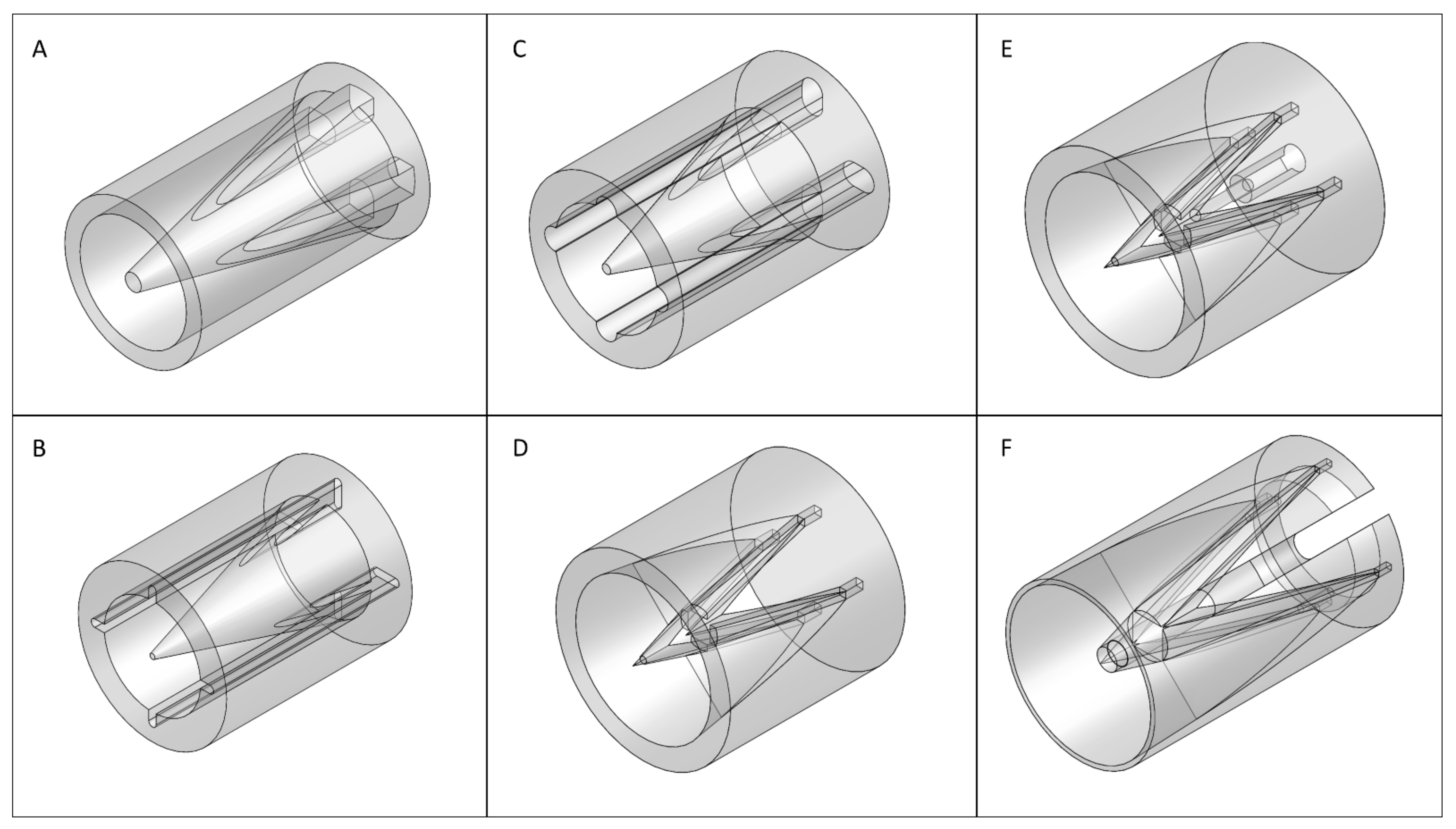





| Cone Type | Cone Angle (°) | Friction Coefficient | Speed (mm/s) | Final Deformation (mm) | |
|---|---|---|---|---|---|
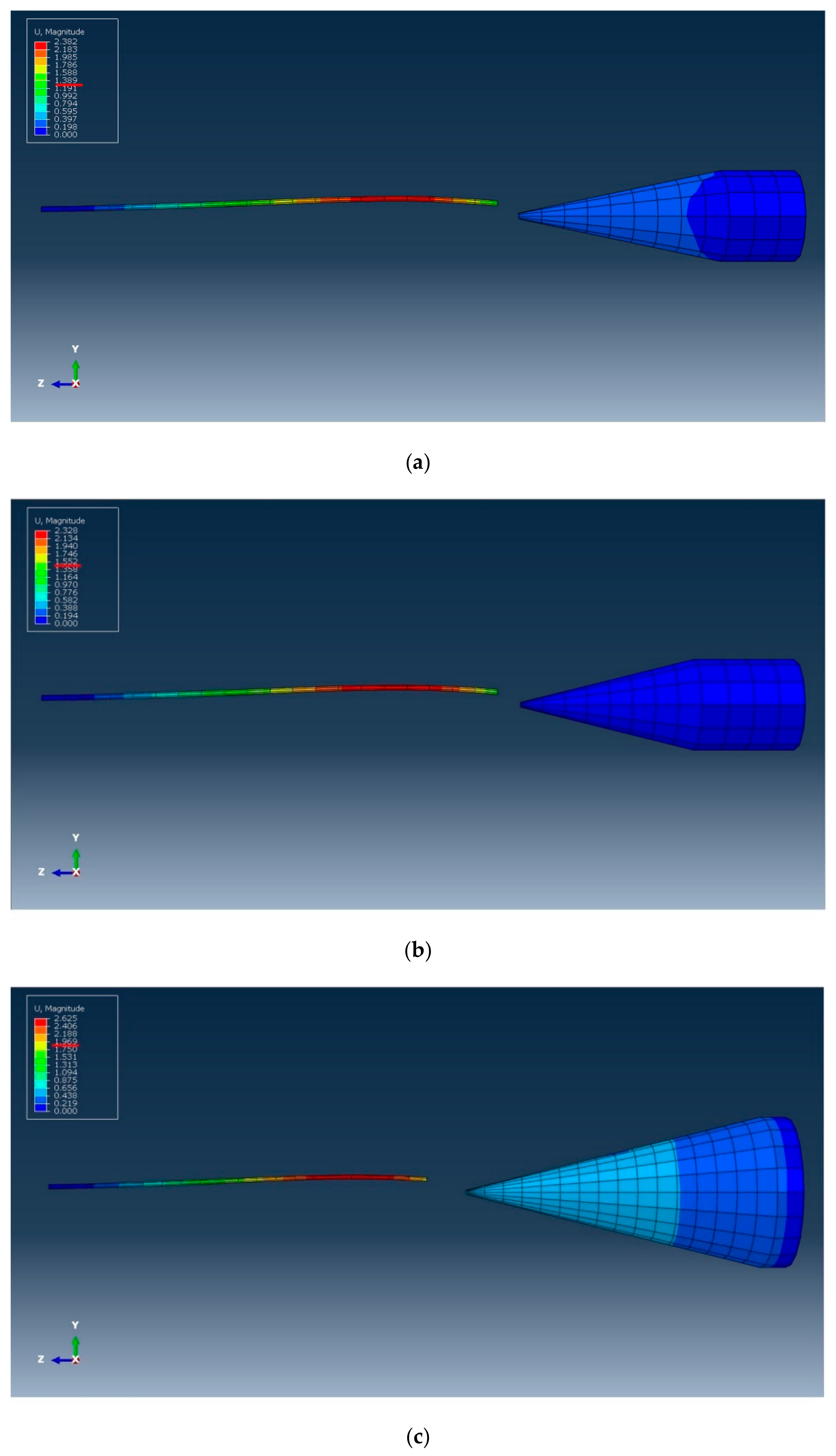
| Cone A | 12 | 20 | 0.33 | 2 | 1.38 |
| Cone B | 14 | 20 | 0.33 | 2 | 1.55 |
| Cone C | 14 | 40 | 0.33 | 2 | 1.96 |
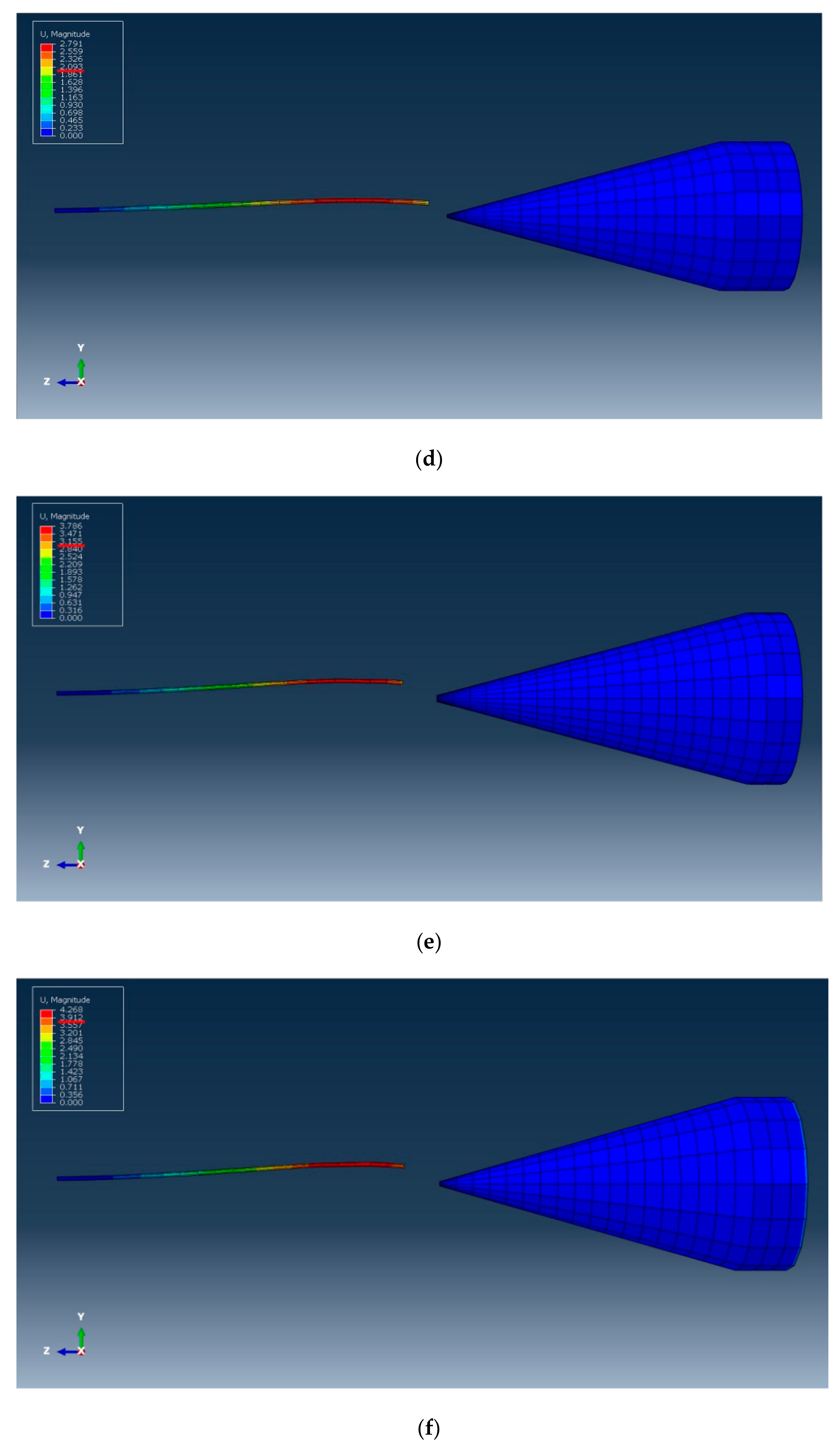
| Cone D | 15 | 40 | 0.33 | 5 | 2.25 |
| Cone E | 15 | 50 | 0.33 | 5 | 3.15 |
| Cone F | 16 | 50 | 0.33 | 5 | 3.75 |
| Simulation Results of Design and Experimental Parameters | |||||
|---|---|---|---|---|---|
| Type | Speed (mm/s) | Cone Angle (°) | Hole Spacing (mm) | Simulation Results | |
| A | 2 | 16 | 12 | 5 | NG |
| B | 2 | 2 | 14 | 8 | NG |
| C | 2 | 2 | 14 | 21 | NG |
| D | 5 | 2 | 15 | 24 | NG |
| E | 5 | 2 | 16 | 24 | NG |
| F | 5 | 2 | 16 | 48 | OK |
| Quadrant | 1st Quadrant | 2nd Quadrant | 3rd Quadrant | 4th Quadrant |
| 90° | 180° | 270° | 360° | |
| pulse |
| Number of Experiments | The First Time Separate Job Succeeded (8 s) | The Second Time Separate Job Succeeded (16 s) | More than Three Times Separate Job Succeeded (24 s or More) | Separate Job Failed |
|---|---|---|---|---|
| 1–10 | 6 | 4 | 0 | 0 |
| 11–20 | 8 | 2 | 0 | 0 |
| 21–30 | 6 | 2 | 1 | 1 |
| 31–40 | 7 | 3 | 0 | 0 |
| 41–50 | 7 | 1 | 0 | 2 |
| Total | 34 | 12 | 1 | 3 |
Publisher’s Note: MDPI stays neutral with regard to jurisdictional claims in published maps and institutional affiliations. |
© 2022 by the authors. Licensee MDPI, Basel, Switzerland. This article is an open access article distributed under the terms and conditions of the Creative Commons Attribution (CC BY) license (https://creativecommons.org/licenses/by/4.0/).
Share and Cite
Lin, Y.-R.; Lin, Y.-C.; Ho, C.-C. Digital-Twin-Based Flexibility Wires of a Circular Connector Automatic Disassembly Process. Robotics 2022, 11, 120. https://doi.org/10.3390/robotics11060120
Lin Y-R, Lin Y-C, Ho C-C. Digital-Twin-Based Flexibility Wires of a Circular Connector Automatic Disassembly Process. Robotics. 2022; 11(6):120. https://doi.org/10.3390/robotics11060120
Chicago/Turabian StyleLin, Yu-Ren, Yu-Cheng Lin, and Chao-Ching Ho. 2022. "Digital-Twin-Based Flexibility Wires of a Circular Connector Automatic Disassembly Process" Robotics 11, no. 6: 120. https://doi.org/10.3390/robotics11060120
APA StyleLin, Y.-R., Lin, Y.-C., & Ho, C.-C. (2022). Digital-Twin-Based Flexibility Wires of a Circular Connector Automatic Disassembly Process. Robotics, 11(6), 120. https://doi.org/10.3390/robotics11060120


