Article

User Study to Validate the Performance of an Offline Robot Programming Method That Enables Robot-Independent Kinesthetic Instruction through the Use of Augmented Reality and Motion Capturing

1
Department of Mechanical Engineering and Building Services Engineering, Technische Hochschule Nürnberg Georg Simon Ohm, 90489 Nuremberg, Germany
2
Department of Mechanical Engineering, Chemnitz University of Technology, 09107 Chemnitz, Germany
*
Author to whom correspondence should be addressed.
These authors contributed equally to this work.
Robotics 2024, 13(3), 35; https://doi.org/10.3390/robotics13030035
Submission received: 20 January 2024 / Revised: 12 February 2024 / Accepted: 15 February 2024 / Published: 23 February 2024
(This article belongs to the Special Issue Digital Twin-Based Human–Robot Collaborative Systems)

Abstract

:
The paper presents a novel offline programming (OLP) method based on programming by demonstration (PbD), which has been validated through user study. PbD is a programming method that involves physical interaction with robots, and kinesthetic teaching (KT) is a commonly used online programming method in industry. However, online programming methods consume significant robot resources, limiting the speed advantages of PbD and emphasizing the need for an offline approach. The method presented here, based on KT, uses a virtual representation instead of a physical robot, allowing independent programming regardless of the working environment. It employs haptic input devices to teach a simulated robot in augmented reality and uses automatic path planning. A benchmarking test was conducted to standardize equipment, procedures, and evaluation techniques to compare different PbD approaches. The results indicate a 47 % decrease in programming time when compared to traditional KT methods in established industrial systems. Although the accuracy is not yet at the level of industrial systems, users have shown rapid improvement, confirming the learnability of the system. User feedback on the perceived workload and the ease of use was positive. In conclusion, this method has potential for industrial use due to its learnability, reduction in robot downtime, and applicability across different robot sizes and types.

1. Introduction

The global shift towards high-mix, low-volume products is a result of recent market transformations that have created a buyer’s market, due to a shift in consumer mentality [1,2]. The trend towards mass customization poses new challenges for traditional robotic automation. Robots often need to be reprogrammed, making the cost of using robots prohibitive for small- and medium-sized enterprises (SMEs) [3].
Businesses, especially SMEs, rely on common programming methods, like using a teach pendant in the form of lead-through or walk-through programming, which falls under the category of online programming methods [3]. Online programming is very popular in this context because it does not require any actual programming knowledge, but it can use up a significant amount of robot resources over a prolonged period, resulting in a low cycle time. Realigning the robot with the teach pendant is a time-consuming process, but it is essential for welding tasks, for example, to avoid thermal deformation [4].
Fortunately, offline programming approaches can minimize downtime and singularity issues by predefining and simulating every movement of the robot arm. Offline programming has some limitations when used in small-scale productions. Capturing the environment and aligning the virtual components as they are positioned in the real world is a common issue. Furthermore, performing pure offline programming requires specialized training and programming skills to create all movements in an abstract virtual environment, possibly with code, and to later transfer them to the actual cell on the shop floor [5].
To summarize, online programming using walk-through or lead-through methods with a teach pendant is highly immersive, since it occurs in the actual cell, requiring minimal programming skills and no additional calibration steps. Offline methods, in contrast, usually enable the early identification of singularities through simulation. This allows for the optimization of the program without using a robot, ultimately reducing downtime. What is needed is a method that combines these features, works offline to minimize downtime, is easy to learn due to its high degree of immersion, and does not increase the effort required for the digital model. Possible answers to this question could be methods that are summarized under the terms programming by demonstration (PbD) or learning from demonstration (LfD). These methods allow for the rapid creation of robot programs without the need for extensive specialized knowledge. The objective is to develop a PbD method that does not require the robot during the programming phase while still providing a high level of immersion. Augmented reality may be the solution to achieve immersion in an offline PbD method. However, finding solutions that address spatial separation between real and virtual content is important. For instance, how to capture trajectories without an accurate computer-aided design (CAD) model of the cell, how to make all target frames accessible, and how to avoid collisions with real objects. In addition to spatial calibration of real and virtual content, creating suitable interfaces between humans and simulations is crucial.
To address this research gap, an Augmented Reality (AR)-based offline programming method has been developed that separates the robot in time and space from its working environment during the programming process and is called Virtual Kinesthetic Teaching (VKT). VKT uses an augmented reality AR simulation to generate the process steps in the robot program. It is independent of the physical robot hardware and enables the teaching process in an environment separate from the production area. To capture the necessary trajectories and commands for the robot using VKT, only the workpiece that will be processed by the robot is required. This allows the real robot to work on another workpiece simultaneously with the programming process, reducing downtimes. This efficient separation of the teaching process from the robot hardware also offers significant potential for safe learning when working with collaborative robots. It enables the training of complex tasks without the risk of injury and facilitates the integration of human–robot interactions into the production process.
To evaluate the VKT and various conventional kinaesthetic teach-in methods, a user study was conducted. The study considered application-specific performance measures, such as frame placement accuracy and programming time, as well as subjective factors like user-friendliness and learnability of the process. As part of the user study, the researchers used the same collaborative robot for both VKT and the conventional kinaesthetic teach-in method.

2. Related Work

This section discusses programming methods for industrial robots and how to evaluate their efficiency. It starts with a summary of current programming techniques, followed by an overview of approaches to compare and validate different programming methods. Lastly, an overview of current intuitive programming methods from research is given. Used keywords and databases can be found in the Appendix A. The objective of this work is to identify the challenges that must be overcome to make robot programming accessible to non-experienced operators.

2.1. Overview of Modern Programming Methods

There are different ways to subdivide the programming methods. For example, one can make a subdivision according to the components involved in programming a robot system. This results in various so-called centerings, such as robot-centered, task-centered, and guidance-centered [6].
One of the most common classifications is based on the interaction between the robot and the user during the programming process. This classification divides the methods into three groups: online, offline, and hybrid, which includes elements of both. The term online means that the robot is directly involved in the programming process and, therefore, production is interrupted. In offline programming, the actual programming process can be carried out independently and is usually software-supported. Offline methods are preferable when it comes to the efficient use of robot resources. However, a hybrid method is often used, where the control flow is determined offline and certain parameters are set online. Robot programming with augmented reality (RPAR) occurs in a semi-virtual environment with a simulated robot on the factory floor. Prior to executing the actual operation, the virtual robot synchronizes with the real robot [7,8,9].

2.2. Validation of Programming Methods

As shown in the previous section, the number of methods and approaches of demonstration-based programming methods is quite diverse. The variety makes it difficult to compare the methods with each other. Various researchers, such as [10], attempt to determine insights into the ease of use, physical and mental load on participants, and time requirements of their method through user studies. Table A1 lists the different validation methods and measurement parameters of various papers.
In [3], a user study was conducted with 20 participants and two test applications. The participants were tasked with creating a welding and a pick and place application using the developed prototype. To determine the method’s intuitiveness, programming time and subjective evaluations in six different areas were measured through a straightforward questionnaire. Unfortunately, the questions were highly specific to the method described in [3] and cannot be applied to similar methods. Additionally, the survey did not include any general questions about physical or mental load, and there was no mention of the accuracy attained by the participants using the method.
This underlines the statement of [11] that there is no common benchmark test to evaluate the resulting trajectory accuracy, the probability of completing an assembly task, and the intuitiveness of the programming interface. A standard for measuring the achievable path accuracy with a programming method does not yet exist. However, the general standard for recording the performance characteristics of robots can be adapted for this purpose [12]. The standard can be used, for example, to determine the accuracy of individual points that were previously programmed with the method to be tested.
To include humans in the validation of programming, other areas of research should also be considered. Certain approaches have been developed to collect data on human–machine interaction. Worth mentioning is the questionnaire for the subjective consequences of intuitive use (QUESI), which was developed for interaction with mobile devices such as cell phones or tablets [13].
However, the QUESI questionnaire does not refer to the mental or physical load experienced by the user. For this, the NASA task load index [14,15] can be used. Here, the user must describe their load in the areas of mental load, physical load, time demands, performance, effort, and frustration on a scale from low to high, representing, respectively, from good to bad.
The works of [3,10,16,17,18] demonstrate that a user study is an effective means of evaluating a programming method while considering both subjective and objective factors. To conduct the study, a suitable test scenario must be created. Ong et al. evaluate the performance of their method not only with a robotic welding application but also with a pick-and-place application, a preference shared by [17,18]. A clear distinction should be made between objective and subjective parameters when defining test parameters. Usability has been identified as a suitable subjective parameter, as demonstrated by Steinmetz et al. This parameter can be measured using a questionnaire such as the QUESI [13]. The NASA Task Load Index is a suitable instrument for measuring the physical and mental stress experienced by test subjects. Zuh et al., Steinmetz et al., Ong et al., and Quintero et al. use the time allotted for completing the task as an objective parameter. Another parameter for validating the method is the success rate, as used by [17,19,20]. To ensure a more accurate evaluation, measuring accuracy in the form of geometric deviation from the ideal position is a useful tool. A summary of the evaluation methods and associated parameters can be found in Table A1.

2.3. Programming Methods Based on Demonstration

A notable class of online methods is programming by demonstration (PbD) or learning by demonstration (LfD), which in both types is based on learning complex skills after an abstract demonstration phase. LfD tends to require programming at a higher level of abstraction than PbD (with some cases used as a synonym) and the basic requirement for learning new skills is the adaptation of human skills through observation.
Generally, these methods do not require writing manual code or creating complex CAD models of the work environment. During the programming process, a significant reduction in programming time is achieved by having a human demonstrate a step of the process and then having the robot attempt to replicate it. This human demonstration can range from a general posture to a demonstration of finger skills [8,11,21,22].
PbD or LfD methods are effective in streamlining the programming process, even when the CAD models required for traditional offline programming (OLP) are unavailable. Using PbD and LfD techniques, the robot can learn complex sequences of operations by physically demonstrating the task. This learning process takes place on three abstract levels. First, the movements of the human are captured using appropriate tools, depending on the LfD category. These data are analyzed and systematized in the second step, to learn or generalize the robot’s capabilities. The representation of capabilities has a significant impact on the performance of robot capability learning and adaptation. The approaches to capability representation can have different characteristics, such as the dynamical systems method or the probability and statistics method. In the third step, the data are abstracted and adapted to the robot [23,24,25].
Most PbD or LfD approaches fall into the categories of kinesthetic teaching, teleoperation, or passive observation. Kinesthetic teaching is characterized by the learning process being performed with the robot performing the task itself [26,27].
Many PbD or LfD approaches are confronted with the so-called correspondence problem. The problem is that human and robot bodies differ in their kinematic structure and dynamic behavior, which leads to mapping challenges. For example, in observational learning, the human pose must be recognized by cameras, adapted, and transferred to the robot with possible inaccuracies. The advantage of KT is that the robot’s manipulator is physically moved by pushing and pulling and at the same time the pose is detected by the internal force-torque sensors. This eliminates the calibration problem A X = Y B described in [28], which defines the relative transformations between hand–eye (X) and robot world (Y). The disadvantage is that KT can only be used to learn scenarios that are physically possible for humans. For example, teaching a robot to palletize heavy objects would require significant additional effort [22,29].
The presented work utilizes a range of technologies, including augmented reality and neural networks. The work is categorized into three categories. The first category describes experimental methods at a higher level of abstraction, followed by the more traditional industrial division into online and offline approaches. The authors’ methods and metrics for validating and evaluating their programming methods are presented in each case.

2.4. Experimental Programming Methods

As stated in the introduction, the goal of this work is to develop a PbD method that does not require the robot during the programming phase while still providing a high level of immersion to allow non-experts to participate in the programming process. To achieve this, we will examine various research approaches in more detail below.
In [19], a high-level approach of LfD using a neural network was developed. Both passive observations and active interactions were used to train the network and to create a model. The model was validated by a robotic task. In this task, the robot learned how to use a tool to move an object by passively observing a human. Passive observation comprised 1000 videos of a human pushing objects with different tools. As active interaction, the model had random robot trajectories as well as 1200 kinesthetic demonstrations of pushing tasks. The model had a higher accuracy than the stochastic adversarial video prediction (SAVP) [30] base model.
Schmeckpeper et al. presented a very abstract form of robot programming that is still in an early stage of research. An attempt was considered successful if the distance between the pushed object and the target point was less than 10 cm, which makes the use of this method impractical.
In [20], a PbD method based on kinesthetic teaching was presented. The method promised to be non-posture controlled. A peg-in-hole task was learned by means of a demonstration by a human. For this purpose, the workspace was scanned for objects using a wrist camera on the robot and identified using scale-invariant feature transform (SIFT) [31] features. The human labeled the recognized object by a specific name and performed the grasping process using kinesthetic teaching. Then, the software linked the object, the features, the labels, and the movements of the gripping process. The robot could then independently perform the demonstrated gripping task after a successful identification of the object. The method made it possible to automatically execute previously learned grasping strategies after automatic object recognition.

2.5. Online Programming Methods

Researchers continue to improve these methods by combining different approaches. Steinmetz et al. combined task-level programming, as implemented in the Robot Programming Suite (RPS) from ArtiMinds [32], with kinesthetic PbD and called it Task-Level Programming by Demonstration (TLPbD). The user demonstrated the task through kinesthetic teaching (KT), and the software recognized one of several predefined intentions based on the movement. As a result of the detected intent, a pre-parameterized skill was retrieved. Intention recognition saves the user from having to subsequently assign individual commands (e.g., close or open gripper) to specific points within the trajectory [10].
The work of Steinmetz et al. shows that intention recognition can speed up programming, but it is more error-prone than manual assignment. For an industrial use case, we would recommend using manual mapping, by pressing an input key during trajectory recording. It is important to note that the online TLPbD method consumes more robot resources than the offline method, which offsets the time advantage gained. In the field of observational learning, motion capture systems are frequently utilized, and sophisticated human machine interfaces (HMI), such as augmented reality, offer great potential for simplifying the programming of industrial robots.
Ong et al. presented a programming method for welding robots that projected the robot into the real robot cell via an AR interface. A PC mouse equipped with motion capture markers was used to display the tool center point of the AR robot. Programming was carried out by tracing the target points in the robot cell on the real workpiece with the modified PC mouse. The movements of the AR robot were then calculated by a Robot Operating System (ROS) https://www.ros.org/ (accessed on 14 February 2024) software module based on the tool center point (TCP). In a validation experiment with six test subjects, a virtual weld was drawn on a quarter-circular sheet metal joint [16].
In [3], the aforementioned prototype was used for a welding application, using additional information from a parameterized CAD model. Welds were delineated by selecting particular workpiece features with the modified PC mouse. The actual workpieces were marked with reference points to identify and correspond with the CAD model. Using the additional CAD data, it was expected that the weld would not only be easier to create, but also more accurate.
Schwandt et al. aimed to develop a new, intuitive human–robot interface (HRI) that utilizes AR to reduce the programming phase required for commissioning robot cells in the production line. This is an online programming method where an operator teaches the robot using an AR interface. The method can be applicable to various use cases. Firstly, the robot program was visualized sequentially by an AR trajectory that consisted of connected 3D points and lines. To achieve this, the target point coordinates from the robot program were utilized to display AR objects through a Vufine+ wearable display. To perform calibration, a planar QR code was attached to the end effector to serve as a reference coordinate system for projection tasks in the AR module. It could be recognized by the head-mounted camera. The second use case involved performing a virtual motion simulation of the robot executing the program. In this scenario, only a 3D model of the gripper was moved along the previously described trajectory. The authors aimed to offer visual collision control by projecting the scaled model of the robot end-effector at any point along the trajectory into the AR environment. Programming the industrial robot with a stylus was another use case. Transferring the 6D-coordinate of the stylus’s tip to the controller would replace the need for the teach pendant. A reachability check was performed on the measured point, and if it passed, the point was added to the robot program. A scaled 3D model of the end effector was projected into the image plane instead of using the AR-Stylus [33].

2.6. Offline Programming Methods

Quintero et al. introduced a method for the offline programming of industrial robots, using an augmented reality interface with a Microsoft HoloLens. Holographic images of a Barrett seven-degrees-of-freedom full-arm robot and its trajectory were projected as individual waypoints in the real workspace. To teach a waypoint, users had to aim their head so that a virtual pointer pointed to the desired target. Waypoints could be taught and modified using voice or gesture commands. Calibration involved manually aligning a real reference feature with a virtual one (e.g., visually positioning two nested cubes). In a user study, the authors instructed participants to record a surface path and a free space path using both the developed AR interface and a seven-degrees-of-freedom (DOF) Barrett whole-arm manipulator in gravity compensation mode. Overall, the AR interface expedited the programming process and attained similar results to the surface path task. However, in the free space pick and place activity, the AR interface experienced significantly more unsuccessful attempts. The NASA TLX analysis demonstrated greater cognitive load on the participants and reduced physical load whilst interacting with the AR interface [17].
Bambusek et al. aimed to reduce the user workload and speed up the programming process compared to kinesthetic teaching. They developed an AR application that enables the offline programming of collaborative robots using a Microsoft HoloLens and a table with Spatial Augmented Reality (SAR) projections. The AR application projected a hologram of the robot gripper centrally, at a fixed distance of 30 cm in front of the user’s field of view. On the SAR table, instructions for the programming process were displayed. The user guided the gripper to the desired target point by adjusting the head position and orientation. Gripper rotation was adjusted using HoloLens Air Tap gestures on an AR sphere, and the gripper’s ability to reach the target points was indicated by changes in color. The robot program generated offline in this manner could later be executed by the real robot, a PR2 (Willow Garage, Menlo Park, CA, USA), after calibration via an AR object and the table edge. In an experiment, the authors of the study compared the programming concept with another concept they had developed in a previous paper, in which they programmed the PR2 through kinesthetic learning with the support of SAR projections on the table [18].
The programming methods presented above are listed in Table A1 for better clarity, with the aspects of the technology used, the type of programming method and its validation concept detailed.
To summarize, Zhu et al. [20] showed that kinaesthetic teaching was a method with a high success rate for successfully teaching the robot specific grasping actions. This is supported by the NASA TLX results of [18], which showed that the cognitive load of the method with KT was lower than the gesture control of the simulated robot gripper used in the work. However, this is an online approach, and, in order to combine the efficient resource utilization of OLP with the fast programming speed of PbD, an alternative form of physical demonstration is required.
Observational learning, despite having increased calibration overhead due to the correspondence problem, can provide a solution in this context. This is due to the involvement of several temporally independent steps. These include the observation of demonstrations, often with the aid of visual systems, the extraction of an abstract feature representation, and the performance of the demonstrated task [22,34].
The concept of Bambusek et al. to create a program offline with an AR hologram at a free robot workstation does not use observational learning, but has great potential for human–robot interaction, as it simultaneously uses the advantages of resource-efficient offline programming. The offline programming method in [17], in combination with the low threshold, has the ability to simplify the programming process for certain robot tasks. According to the article, a limiting factor is the calibration and gesture-based control concept, which results in inaccuracy in the placement of waypoints. Quintero et al. mention that shifting the position of the test subjects can lead to an offset of up to 50 mm between the virtual and the real object, which would severely limit the benefits of AR technology. In their work, Quintero et al. point out that it is not always necessary to create a comprehensive 3D model of the robot cell in a simulation environment. Instead, the recommendation of Bambusek et al. can be followed to carry out the programming process at adjustable and mobile robot workstations in order to keep robot downtime to a minimum. A mobile robot workstation is a flexible workplace that resembles an industrial table on castors, for example, and is equipped with various mounting options or small load carriers.
Using such a mobile robot workstation and not using the real robot requires a realistic simulation. To make this offline programming process feel intuitive for the user, it is important to use not only the gripper, as in [18,33], but also a complete augmented reality simulation of the robot’s structure and kinematics. The work of Ong et al. [3,16] show such an advanced AR simulation. The generation of virtual weld seams with a 3D pointing device in the form of a mouse stretched by a motion capture are also very intuitive. Unfortunately, the online nature of the approach increases robot downtimes.
An intuitive teaching concept that places as little cognitive burden as possible on the user is crucial for simple programming. It is therefore more advantageous to use a physical teaching concept, as in [3], than a teaching concept based on the orientation of the head, as in [17,18]. A physical teaching approach, e.g., with a pen-like device, such as [33], enables the precise creation of points by direct touch, eliminating the need to determine them by the intersection of orientation vectors and objects.
In order to consider all aspects of AR robot programming, a reliable calibration of the real robot with the simulation must be developed. Both the purely optical calibration via a QR code, as in Ong et al. and Schwandt et al., as well as the manual placement of AR objects on real objects, as in Quintero et al., have potential for improvement.
In summary, it is clear that a new programming method needs to be developed that can, in principle, be executed offline in order to save robot resources and, at the same time, has a teaching concept that is independent of the cell. For this reason, classic kinesthetic teaching was ruled out, even though it enables a very intuitive and immersive programming process. A largely immersive replacement for the real robot is a realistic AR robot simulation. As [17,18] show, a physical teaching concept gives better feedback to the user than a purely visual or verbal teaching concept and, at the same time, helps to avoid the correspondence problem. To combine a physical teaching concept with offline programming and a sufficiently accurate calibration procedure, an adjustable and mobile robot workstation is required.
Since the combination of all the above-mentioned aspects has not yet been united in a programming method for industrial robots, a new programming method has been developed in this work, which is presented in the following.

3. Offline Programming by Virtual Kinesthetic Teaching

This section describes an offline programming method based on KT with a augmented reality representation of a robot. For more information on specific solutions, such as the hierarchy of object coordination systems or perception of components, see [35]. First, the functional principle of the method and the process flow are described. Subsequently, the realized method is presented in combination with a physical prototype.

3.1. Concept of the Method

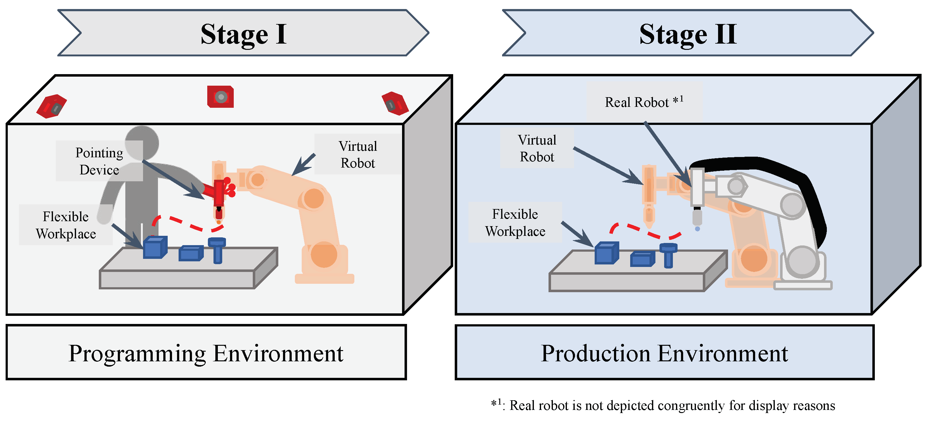
The programming method for industrial robots presented here claims to keep both the duration of the programming process and the robot downtime as low as possible. For this purpose, the method is divided into two stages, which take place in two real rooms and are extended by virtual objects (see Figure 1).
The two rooms do not have to be identical, as long as they have a similar size ratio, which excludes a miniature replica of the real cell. The relevant commonality of the rooms is only the workpieces to be machined and their material carriers or fixtures. One or several workpieces, along with all material supports and fasteners, are hereafter referred to as the flexible workplace (FXW).
During the first stage, the programming process is initiated, where a digital robot replica can be positioned in any desired location and manually controlled by the user with a pointing device (PD). The second stage involves setting up the robot cell by referencing the robot with the FXW and performing physical processing or manipulation. The following section will explain both stages and their respective processes in detail. Figure 2 serves for the graphical illustration of the process flow.
Stage I takes place in a room separate from the shop floor and represents the programming environment. In this context, the term environment is considered to be everything that a person can perceive with their senses. In this example, there are three main objects in the programming environment (see Figure 2, stage I, hexagonal boxes). It contains the FXW, which is to be processed or manipulated by the robot. In addition, there is a virtual image of the physical robot (the virtual robot), which imitates its visual appearance and properties. The last initial main object is a pointing device, which can be used to manually guide the virtual robot in 3D space. All these objects are involved in processes and create further virtual objects, data, and, finally, a template of the application.
Initially, preparatory processes are necessary to perform the actual programming. To address the correspondence problem of offline programming discussed in Section 2.4, a new approach of kinesthetic teaching focusing on the robot’s end effector is used. A physical pointing device controls the virtual robot and interacts with real-world objects on the flexible workplace. The PD serves as an end effector for the virtual robot and provides a physical connection to the virtual robot. To align the objects, the pointer must be calibrated to the FXW first.
This process involves the coordination of all real and virtual objects in the programming environment through spatial coordination. First, a global coordinate system (G-CS) is defined in real space, to which the coordinate systems of the real (see Calibration Element (CE), FXW, PD, and Sensor (S) in Figure 3) objects are referenced. There is a corresponding coordinate system in virtual space for each real object. By using geometric calibration elements (CE) and visual motion capture sensors (S), the transformation   v G C S T v C E =   G C S T C E can be determined (see Section 3.2). Using this transformation, the pose of the pointing device can be mapped to the end effector of the virtual robot. This allows all poses of the objects to be completely represented as an element of the special Euclidean group SE(3) with ( p , R ) SE(3) with p R 3 , R SO(3) at the end of the process.
The programming processes start with the frame creation process. Here, points with six degrees of freedom (6-DOF) are initially generated. They are subsequently paired with commands and now referred to as frames. Thanks to the object matching process, the end-effector of the virtual robot moves synchronously with the PD. The positions of the remaining robot links result from the inverse kinematics (IK) algorithm used and the prevailing transformation between the TCP and the robot’s base reference coordinate system. If the robot takes up a non-ideal overall position, the user must initiate a recalculation. This process is called virtual kinesthetic teaching. The PD can now be used to approach target points in real space, and command buttons can be used to create frames. These buttons are used to assign certain properties to the frames that affect the robot’s path planning. These properties are used to organize the frames hierarchically in trajectories, as well as to initiate a gripping process or similar.
The trajectories created are the foundation for the path planning process. The goal of this process is to generate a continuous robot motion for efficient motion planning. User input is used to define the motion types of the trajectories, and then the necessary data is generated. A distinction is made between simple waypoints, which are used for regular manipulation movements with a start and end point, and complex splines, which can represent, for example, a welded seam. Due to the different types of trajectories, it is necessary to specify the reference coordinate system that the respective trajectory uses. Trajectories that describe the approach and manipulation of a workpiece are referenced to the global coordinate system. Complex splines, on the other hand, which describe how to machine a part, use the workpiece pose as the reference system. This creates the first version of the application template.
The aim of the control process is to identify errors in the application template. The inverse kinematics of the virtual robot are constantly computed in real time in order to execute the entire trajectory with the TCP. Possible errors in the program sequence and collisions with objects can be identified by visually examining the overall robot motion. The robot’s joint angles are discretely recorded and analyzed over time for the application template to automatically verify the reachability of each target point. Through analysis, discontinuities in the joint angle trajectory can be detected, indicating singularities.
If any errors emerge during the control process, it is essential to revert back to the frame creation process. During this process, it is possible to delete frames, to move them, or to link them to other commands. It is also possible to add auxiliary points to the trajectory or components and to reposition virtual robots. A complete re-recording of all robot joint angles is required for robot repositioning. Once stage I is completed without further errors, the FXW is introduced into the production environment. All the generated data is then transferred to stage II.
The manufacturing environment now contains the FXW, the real robot, and the virtual robot. The setup process involves performing a calibration process to determine the actual geometric parameters within the robot cell, which helps identify the model deviations between stage I and stage II. It should be noted that the trajectories recorded in the application template are based on the base reference coordinate system of the virtual robot in stage I, which makes them invalid in the event of model deviations in stage II. To adjust a change in relative position, a measurement run must first be conducted within the real cell. To determine the coordinated transformation, the real robot’s end effector is coupled temporarily to a measuring object at the flexible workstation. This transformation between the robot’s base reference coordinate system and the FXWs coordinate system allows the virtual robot to be adapted to the pose of the real robot. The repositioning results in the need to recalculate all joint angles for the robot program. Through the adaptation and control process, in a similar way to the control process in stage I, a check of reachability and singularity is performed. The user visually monitors the process to detect any errors. If errors arise, the objects require repositioning, or the environment necessitates slight adjustments. Once a flawless run is achieved, the export process can commence. The export process is used to convert the application template into an executable robot application. A source code file is created using a special export format. This source code can be transferred to the respective programming language of the real robot used by means of a converter. Finally, the application is loaded onto the robot’s controller and the program can be executed. If several objects are manipulated or processed in a similar way, it is necessary to jump back to the calibration process.

3.2. Prototypical System and Environment Implementation

In the following section, the prototypical implementation of the method described above is explained and the most important hardware and software components are shown. Figure 4 illustrates how the components interact with each other and in which way data is exchanged. The description does not represent a chronological process flow like in Figure 2 and the spatial allocation of the components is also not shown in Figure 4.
The central hardware component is the workpiece, which is, in this case, permanently connected to the FXW. A setup with several independent workpieces or small load carriers is also possible (see Figure 5a). In this case, all objects must be permanently tracked in position. The FXW is equipped with an optical target and a calibration block. In addition, an AR system consisting of an HTC Vive Pro (HTC Corporation, Xindian District, New Taipei City, Taiwan), a controller and associated tracking system is used. A smart pointing device (SmartPd) is used as a representation of the robot’s end-effector, which can be tracked using an optical target and serves as an input device for additional commands. In addition, the SmartPd can be used to detect contact forces and grip objects. With a motion capture system consisting of six Flex 13 cameras (OptiTrack, Portland, OR, USA), the optical targets can be tracked with sub-millimeter accuracy. A Kuka iiwa LBR R800 (KUKA AG, Augsburg, Bavaria, Germany) is used to execute the tasks in the cell.
The most important software component is the GuideARob-Teach software, developed in Unity 2019.4.20f1 (Unity Technologies, San Francisco, CA, USA), which serves as the central control unit. The software GuideARob-Ex, written in C#, serves as the interface to the Kuka iiwa. For the control of the SmartPd and the wireless communication with GuideARob-Teach the SmartPd-OS is used, which runs on the microcontroller Particle Photon (Particle, Boulder, CO, USA). Commercial tools are utilized for communication with the OptiTrack MoCap system and its software Motive 2.2.3 (OptiTrack, Portland, OR, USA), as well as the AR system from OpenVR (Valve Corporation, Bellevue, Washington, DC, USA).
The AR system consists of modified Virtual Reality (VR) glasses (HTC Vive Pro) with two associated tracking sensors (Base Station 2.0) and a modified HTC Vive controller. With the help of the developed software GuideARob-Teach and the VIVE SRWorks SDK [36], the full potential of the VIVE VR system could be utilized and the glasses could be used in the context of AR pass-through technology.
Object matching takes place via the MoCap system and the various optical targets fixed at the FXW (see Figure 6a), as well as via the calibration block (see Figure 6a,b) and the AR system. Since the AR system has its own tracking system and the controller can be connected temporarily to the calibration block, it is possible to link the real objects (video feed) and the virtual content. Once the AR system is calibrated, the virtual robot’s TCP and the SmartPd’s TCP must be matched. To do this, the SmartPd’s calibration tip (see Figure 6c) is inserted into the calibration block and the virtual robot assumes its calibration pose. In this configuration, a transformation can be performed to adjust both TCPs.
The workpiece can be detected by attaching it to the FXW or by using a separate optical target. The target’s six mechanical degrees of freedom can be determined using a camera system. The SmartPd is used to specify the destination point for the TCP of the virtual robot. At the same time, the robot base reference coordinate system is defined in the software via a fixed relative position to the FXW. From this, the inverse kinematics solver can be used to compute the joint angles of the virtual robot. The multi-objective IK solver used here is called Bio-IK and internally uses a hybrid evolutionary algorithm [37]. In conjunction with a corresponding CAD model of the Kuka iiwa, a realistic simulation of the robot can be achieved (see Figure 5b). As the virtual robot follows the SmartPd, the user can set individual frames, including additional commands, at the push of a button.
If the TCP is in the correct position during frame creation, but the position of the remaining robot links is not optimal, which can happen with a 7-DOF robot, a recalculation of the IK can be triggered by pressing a button on the SmartPd. The individual frames are hierarchically assigned to specific trajectories. The reference coordinate system of the trajectories is linked to an optical target, which is permanently connected to the FXW or the workpiece. This allows the FXW or workpiece to be moved in space without the frames changing in relation to their reference object. The trajectories can be either simple movement types, like point to point (PTP), or complex spline movement types. Command keys on the SmartPd can be used to link additional parameters to them. This results in the application template, which shows the entire movement of the robot TCP relative to the reference object. To avoid errors, the application template is permanently synchronized with the virtual robot. This means that frames can only be created if they are reachable by the robot. In addition, the user receives a permanent AR visualization of the robot and the frames set via the AR module and the HTC Vive.
To set up the Kuka iiwa in the cell, its TCP can be temporarily connected to the calibration block, and the position of the coordinate system can be calculated using the joint angles. The virtual robot will now be automatically moved to the position of the real robot for adaptation. Subsequently, the application template is simulated again with the virtual robot and the final application is created. If there are no singularities or collisions and all points are reachable, an offline data package is created using the export module, which is then converted to Kuka iiwa source code using GuideARob-Ex. GuideARob-Ex enables the adjustment of individual frames or trajectory parameters, such as TCP speed, when necessary. Finally, the source code is loaded to the controller of the Kuka iiwa, and the application can be executed.
The prototype, and, in particular, the SmartPd haptic input device, are subject to various limitations in terms of the type of application, component handling, and accuracy. The range of possible applications depends on the interchangeable tip selected. Currently, there is a probe tip for creating welding, gluing, grinding, and handling applications. There is also a gripping tip that can be used to handle and assemble small parts in the range of 400 g and 4 × 7 × 10 
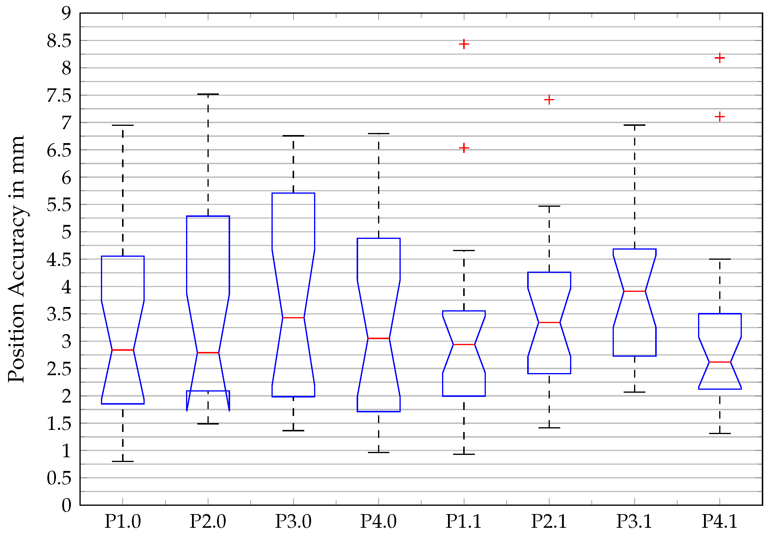
cm. The user must compensate for the weight of the SmartPd and the part during the learning process. In conventional KT, the robot’s own weight and, when appropriate, the weight of the component, can be compensated. Thus, KT offers certain advantages. However, an initial torque in the joints must be overcome in order for the robot to move, which can lead to overshoot for very fine tasks. For larger, heavier components, the gripping position can also be specified using the probe tip of the SmartPd. With this method, the limiting factor is the payload and opening width of the robot and gripper used later. The same applies to the size of the usable workspace. The SmartPd can operate in the field of view of the MoCap cameras in a radius of up to 5 m, but the actual usable workspace is limited by the robot selected later. The accuracy of the system is studied in Section 5 and is also limited by the robot.

4. Study-Based Validation for Programming by Demonstration Methods

The objective of this section is to develop a benchmarking test on programming methods based on demonstration. This test validates the applicability of robot programming methods for industrial applications through a study with a number of independent subjects.

4.1. Study Objective

The method from Section 3.1 is subjected to this benchmarking test to prove or disprove the following hypotheses:
The method allows inexperienced users with no robot programming knowledge to create a complex robot program without significantly decreasing the maximum achievable accuracy of frame placement or increasing the programming time.
To confirm or refute the hypothesis, various data must be collected. First, the maximum achievable accuracy of frame placement is measured. In addition, the required programming time must be recorded. Furthermore, the subjective impression of the test persons regarding the programming process is determined. This impression is examined with regard to the ease of use and how quickly the application of the method can be learned.

4.2. Study Design

As mentioned in [11], there is no standard method for measuring the performance of PbD or LfD methods. Accordingly, there is no established study design as there is for clinical trials. In the following section, an attempt is made to provide a design for studies of this type.
A total of 16 subjects of different gender, age, and knowledge participated in the study. Detailed information about all subjects, including who did which test how often, can be found in the Appendix B.1. Subjects were divided into three different user groups, based on their experience with the test application and prototype. User group one were experiencing the trial for the first time and were referred to as inexperienced users. User group two were subjects who were undertaking the trial for the third time and were referred to as advanced users. User group three consisted of users with a lot of experience using the prototype from Section 3.2 and who had run the test application multiple times.
The study consisted of 25 trials, each containing Task A and B, performed by each subject once or multiple times. The participants who completed the test multiple times were selected at random. Table A2 contains a list of these participants. The subjects had to assemble a simplified table using the prototype from Section 3.2 in an office-like environment. The template of the table is from Zeylikman et al. and the assembled object can be seen in [38] Figure 4a. A list of all components can be found in [38] Table II. In the initial phase of the test, the composite T-Type elements (T1, T2, T3, and T4) and the foot F-Type elements (F1, F2, F3, and F4) were stored in a small load carrier. The four table legs D-Type elements (D1, D2, D3, and D4) were placed in a horizontal fixture and the tabletop in a customized fixture (see Figure 7). The subjects had to pick up and place the different parts with the haptic device and the gripper tip (see Figure 7b). The user had to be aware, not only in order to perform the assembly correctly, but also to perform it in a way that was feasible for the robot without singularity or reachability problems. The individual process steps for Task A and B are listed in Table A4).
To quantify the results, the assembly process described above was repeated by a control group, using a conventional kinesthetic teaching method. In this case, the prototype was substituted by a Kuka LBR iiwa R800 with a 2-jaw parallel gripper, while the experimental set-up, such as the objects used and the small load carriers, were otherwise identical. For the conventional kinesthetic teaching, we utilized the Kuka hand-guiding teaching. The robot was put into hand-guiding teaching by pressing the release button on the robot flange. By pressing the confirm button on the robot wrist, the frames were saved and the grasping process was initiated. The experiment comprised five test series, with both task A and task B were performed in each series. The control group consisted of one experienced operator per test series with knowledge of the Kuka iiwa and the hand-guide gauge, who carried out each test series. No subjective evaluations were considered in the control group, since the test group was already well acquainted with the Kuka iiwa and the hand-guiding teaching. Therefore, only the measured values for required programming time and the maximum achievable accuracy of frame placement were recorded. Each test run included all steps for Task A and B from Table A4.

4.3. Measured Values to Be Collected

The following section describes the measurement procedures and methods used to obtain the data described above.

4.3.1. Time Effort

For each subject, the time t t o t a l required for test task A and test task B was measured at the first participation in the study. To determine the time per frame T p F , the number of frames n F generated was divided by the total time needed ( T p F = t t o t a l n F ). This time effort was then compared with conventional online programming methods in total and per frame.

4.3.2. Positioning Accuracy

Positioning accuracy was determined in conjunction with A at all eight target points ( P n . m with n [ 1 ; 2 ; 3 ; 4 ] and m [ 0 ; 1 ] , see Figure 7) and across all user groups (inexperienced, advanced, and professional). When gripping T-objects on their cylindrical shafts with the SmartPd, the spatial information was acquired with GuideArob-Teach and the MoCap system at the specific process steps (see Appendix B.2).The positioning accuracy used here gave the deviation of the reached position and the barycentre (mean position over all measurements) for the respective target point ( P n . m with n [ 1 ; 2 ; 3 ; 4 ] and m [ 0 ; 1 ] ) and was calculated according to the Formulas (1) and (2).
In order to determine whether there was a significant difference between the positioning accuracy at the different target points, a one-way analysis of variance (ANOVA) was performed. For this, the data of the positioning accuracy had to first be tested for normal distribution using a quantile–quantile plot and a Kolmogorov–Smirnov test.
P D n . m = ( x ¯ n . m x i ) 2 + ( y ¯ n . m y i ) 2 + ( z ¯ n . m z i ) 2
x ¯ n . m = 1 i x n . m , i y ¯ n . m = 1 i y n . m , i z ¯ n . m = 1 i z n . m , i

4.3.3. Distance Accuracy

The distance accuracy was used to compare the VKT to a conventional KT in terms of accuracy. This measurement procedure from [12] (Section 7.3.2) was actually intended for determining the performance parameters of industrial robots. In this work, it is used to determine the accuracy of teaching frames within a grasping task trial. The distance accuracy A D P is the difference between the mean measured distance D ¯ and the command distance D e (see Equation (5)). The measurement of the four different tracks (A1, A2, A3, and A4) between the pickup and drop of the T-objects ( P n . 0 to P n . 1 at n [ 1 ; 2 ; 3 ; 4 ] ) is used. This measurement method was chosen because the T-objects have fixed starting positions on the workpiece supports, but can be gripped at different points on the cylindrical shaft. Therefore, the sole measurement of the absolute gripping points is an insufficient indicator of the quality of the experiment. For this reason, the measurement of the relative distances of the gripping process is also part of this study. To reduce the effect that the errors of two measuring points cancel each other out, D ¯ is not formed from a single pair of measuring points, but from the mean of all measurements of the respective traces A1 to A4. To determine the command distance D e for all four tracks, a measurement is made using a Platinum measuring arm and a Laser LineProbe LLP V3 (FARO Technologies, Lake Mary, FL, USA), which has an accuracy of 25 μm. By additionally determining the distance accuracy, the teaching process with the two systems (the prototype and Kuka LBR iiwa) can be tested with respect to an absolute command value ( D e ) using a standardized procedure [12] and an established measuring medium (FARO Platinum).
A D P = D ¯ D e
D ¯ = 1 n j = 1 n | P 1 J P 2 J |
D e = | P e 1 P e 2 |

4.3.4. Measuring the Ease of Use

The subjects received a questionnaire to determine the ease of use of the method in combination with the current prototype. The questionnaire contained questions in three categories. The first category related to programming methods in general and was partly based on QUESI [13], the second to the task load perceived by the subjects, and the third to specific characteristics of the respective programming method. The task load assessment was based on the NASA task load index [14,15] and was extended by additional questions. The questionnaire aimed to gather the subject’s unbiased subjective impression of the programming method after using the prototype for the first time. The original questionnaire can be found in the Appendix B.3. All method-related questions were worded positively and subjects could express their agreement with the question with one (no agreement) to ten points (total agreement). For the evaluation of the questionnaire, the mean value over all subjects was calculated for each question and category. The overall evaluation of the ease of use of the method was conducted using the mean point score of the three categories.

4.3.5. Learning Progress

It is assumed that the more often the task from Section 4.2 is repeated by a subject, the higher the achievable positioning accuracy. This assumption is based on the principle of learning by reinforcement. This basic principle of motor learning states that the degree of performance improvement depends on the number of exercises. Motor learning in a cognitive approach means the stabilization of an efficient movement sequence on the basis of specific processing information. It is assumed that each execution of a movement leaves its traces in the human central nervous system. With repeated successful execution of the movement, these traces are deepened. This increases the probability that further movements will follow this trace and be more successful. The repetition of movements is considered one of the most effective methods for improving motor performance [39,40,41,42,43].
A proven model of motor learning includes a total of three stages. They are called the early learning phase (stage 1), the consolidation phase (stage 2), and the retention phase of motor sequence learning (stage 3). It should be noted that the transition between stage 2 and 3 is very fluid, making it difficult to distinguish [44].
In this study, it was assumed that the inexperienced user group experienced stage 1. The subjects quickly learned the basics of the movement through the short practice, and the process could be fully performed by them. The advanced user group was at stage 2, having developed their fine coordination through repeated use of the system. Their performance improved through training and they became more resistant to interference. During each trial, users received tactile feedback from manipulating the parts with the SmartPd, while also obtaining visual feedback from the simulation. The simulation permanently checked the reachability of the robot and let the user create only suitable frames. The professional user group showed stabilization of fine coordination due to a high repetition rate; they undertook through the process very smoothly. Performance optimization occurred at a slower learning rate. On the other hand, they could perform the task with decreasing attention. As a result, the increase in accuracy per repetition was an indicator of the learning process.
This study assumes that the more frequently the test is carried out or the application is used, the greater the accuracy achieved. This increases the probability of learning success. To prove this, the inexperienced group performed Task A once, the advanced group performed it three times, and the professional group performed it at least ten times. The positioning accuracy at the different pick-up and drop-off points (see Figure 7, P n.0 and P n.1) was evaluated separately for each user group. The positional accuracy was calculated as in Section 4.3.3, and the median of each user group was used as the reference value for learning success.
An analysis of variance was required to determine whether there was a significant difference between the three user groups (categorical variables) with respect to positioning accuracy (metric variables). The normal distribution test was conducted in a similar fashion to the discussion in Section 4.3.2. Since an ANOVA needs to be performed with independent samples, each test person may only appear once in the statistics, which is why the user groups were filtered and reduced accordingly. After performing the ANOVA with significance level α = 0.05 , the groups were tested against each other with a multiple comparison test [45].

5. Results

This section shows the results of the user study, including the parameters time effort, ease of use, distance accuracy, and learning process.

5.1. Time Effort

For all subjects who participated in the study for the first time (see heading of Table 1 and Table A3), the average time required and the average number of frames were calculated (see Table 1). The subjects needed an average of 5 min for task A and placed an average of 41.3 frames (including grab and move commands). For task B, they needed 9 min and 16 s and placed 61.6 frames. Overall, the average time per frame for task A and B was 9.1 s/F. This corresponded to a time saving of 46.8 % , compared to the control group with the conventional programming method using Kuka hand-guiding.

5.2. Positioning Accuracy

The results of the positioning accuracy are summarized in Figure 8. All recorded frames across all user groups were assigned to the individual target points. The median of the target points was very close, whereby the most accurate placement of the frames was P D 4.1 = 2.6 mm and the most inaccurate P D 3.0 = 3.4 mm. The quantile–quantile plot (see Figure A1) and the one-sample Kolmogorov–Smirnov test showed that the positional accuracy data were normally distributed. The ANOVA showed that there was no significant difference between the categorical variable position and the variable positioning accuracy with F = 0.71 , p = 0.663 at a significance level of α = 0.05 .

5.3. Distance Accuracy

The determined average absolute distance error over all trials (V03 to V24) and over all four tracks (A1 to A4) was A D a l l , V K T = 3.31 mm. The averaged distance deviation error related to the respective track showed considerable fluctuations (see Table 2). Within the control group, there were noticeable variations between the individual traces. Nonetheless, it can be noted that the control group showed less distance error when using the Kuka hand-guiding ( A D a l l , C o n v . K T = 1.37 mm).
A comparison of VKT usage among the three distinct user groups revealed significant discrepancies in both the scatter and the maximum and mean values (see Figure 9). The inexperienced users, who performed the trial (Task A and B) for the first time, recorded the largest scatter, with a deviation of up to 10 mm. The advanced user group repeated the trial three times and showed significantly lower scatter values compared to the inexperienced users. The interquartile range used here to quantify the scatter was I Q R i n e = 3.61 for inexperienced, I Q R a d v = 3.04 for advanced, and I Q R p r o = 0.912 for the professional user group.
The advanced group achieved a lower mean error in distance accuracy than the inexperienced group. The group of professional users had used the prototype at least ten times and achieved the best values for the mean distance accuracy with A D a d v = 2.24 mm. Moreover, the scatter of the values in the conducted experiments was extraordinarily low.

5.4. Ease of Use

The ease of use of the method was rated as 7.9 out of 10 possible points (see Table 3). The method was generally regarded as positive, and the evaluation of the individual functions was also very positive. Only the physical and psychological load of the test persons was in the midfield, with 4.94 points (see Table A5). The free text questions on positive and negative aspects of the method, as well as on suggestions for changes, were rated as follows, according to the frequency of responses. About 38 % of the respondents perceived the programming method’s ease of use to be positive. The simulation of the robot and its movements was mentioned positively by 31 % of the subjects. A quarter of the subjects noted the short training period or the quick learning of the method as positive. In response to the question “What did you notice negatively about the method?”, half of the respondents said that they disliked the poor image quality provided by the VR head-mounted display. Around 31 % of the respondents found using the SmartPd physically demanding and criticized the ergonomics of overhead gripping tasks. One eighth of the respondents criticized the poor pressure sensitivity of the input buttons on the SmartPd. The subjects made various suggestions for improving the method and the prototype. About 19 % of the subjects wanted a visualization showing the order of the frames already set. Connecting the individual frames with a straight line as well as sequential numbering of the individual frames were suggested. A proportion of 12.25 % of the subjects suggested a visualization with a higher resolution VR or AR head-mounted display (HMD), or by means of a handheld or stationary external screen. All free text answers can be viewed in Appendix B.3.4.

5.5. Learning Progress

Differences in positional accuracy were found between the inexperienced, advanced, and professional user groups. The user groups differed in the number of uses and achieved median positioning accuracy scores of P D m e a n , i n = 4.03 mm, P D m e a n , a d = 2.98 mm, and P D m e a n , p r = 2.29 mm when the test was performed once, three times, and at least ten times, respectively. The ANOVA in combination with the normal distribution test from Section 5.2 showed that there was a significant difference between the categorical variable number of uses and the variable positioning accuracy with F = 12.91 , p = 8.6 · 10 6 (see Table 4 and Figure A3). The multiple comparison test [45] based on the ANOVA showed that there was a significant difference between all groups. A statistically significant positive correlation between the number of uses and the achievable positional accuracy could be proven.

6. Conclusions

The results of the user study confirm the hypothesis from Section 4.1 and show that the presented method enables a wide range of users to create a complex robot application. The data show that the VKT in combination with the current prototype can compete with a conventional KT method. For the user study conducted, the assembly of a small table was simulated with the help of an industrial robot. By using this complex assembly task, which involves many individual steps, the method could be examined for various aspects. Unfortunately, the experimental setup created for this purpose had certain weaknesses when it came to determining the exact accuracy. The low stiffness of the components and the user-selectable gripping point of the components caused a variety of disturbances that were difficult to quantify. Therefore, the position and distance accuracy determined in this study serves as a first indication and for the first estimation of possible fields of application of the method. The mean positioning accuracy over all groups and target points to be approached is 3.4 mm. This value can be understood as a kind of three-dimensional standard deviation, since it refers to the common center of gravity of all created frames and thus provides an indication of the dispersion. Furthermore, no dependence of the positioning accuracy on the target points to be approached could be determined. For distance accuracy, a comparison was made between VKT and conventional KT. The prototype presented in Section 3.2 and the commercial robot system Kuka LBR iiwa R800 in hand-guiding mode were used. The results show that components can be moved from point A to point B with the VKT by skilled operators with an accuracy of A D p e r = 2.2 mm. In contrast, it was shown that the same process can be performed with the commercial system with an average absolute distance accuracy of A D i i w a = 1.4 mm. The SmartPd’s external tracking method provides reproducible and reliable results, although it falls behind conventional systems. When compared to AR techniques like that of [17], which utilize the HoloLens’ built-in sensors for tracking, VKT avoids significant offsets of several centimeters, even when the user’s field of vision is impaired.
To test usability, a questionnaire was created, consisting of a combination of specific questions and questions from [13,14]. The procedure’s ease of use received a rating of 7.9 out of 10 points. The positively phrased test questions were widely agreed upon by the users. The physical and mental stress of the subjects was rated as neutral, which was partly due to the high weight of the SmartPd and the low image resolution of the HMD, according to the free-text questions. To investigate the learning process of the method, the differences in positioning accuracy of the three user groups were examined. A statistically significant difference was found. This confirmed the hypothesis that there is a relationship between the frequency of use of the method and the accuracy achieved. This confirms that there is a learning success in using the method. VKT shows very high potential in terms of efficient uses of robot resources. Since the VKT allows the teaching process to occur offline, the robot’s downtime is minimized, as only a straightforward calibration process is required. In addition, a savings in pure programming time of 46.8 % was achieved during the study, compared to KT with the commercial system.
In terms of accuracy, the results of the control group of the conventional KT could not be achieved. This shows certain limitations of the method, which are due to the fact that only one representative of the robot end effector is used. It can therefore be said that, in terms of accuracy, the method is more suitable for applications that require accuracy in the millimeter range or can be actively recalibrated. An example of this would be, for example, a robotic welding application where an active welding gun corrects the path during execution. However, prototype-related factors must also be taken into account here, which is why no fair comparison with an industrial product is possible. The hardware-related low resolution of the VR goggles and the too-compliant gripper had an influence on the distance accuracy. Nevertheless, the accuracy that has been achieved so far should already be sufficient for certain applications in material handling or in the packaging application area. Furthermore, this method provides significant benefits in terms of downtime, by enabling the quick offline teaching of a vast number of frames. Additionally, it allows for safe and effortless teaching, as the robot is not at risk of collision. The method also facilitates the teaching of very large or insensitive robots, thereby providing new opportunities. Overall, the first user-based study shows very satisfactory results and indicates a high potential of the method for industrial use.

7. Outlook

Further studies should be carried out to investigate the general applicability and further potential of the method for other diverse applications such as welding, bonding, and grinding. The study suggests that the method could be most valuable in creating complex trajectories. Therefore, accuracy should be examined in an application that utilizes the probe tip of the SmartPd. To this end, further improvements should be made to the prototype based on the user study. First, the visualization should be improved by increasing the resolution of the HMD and improving the placement of information in the field of view. For example, trajectories can be tagged with virtual information labels to indicate the flow of the application. In addition, there is room for improvement for the SmartPd, in terms of the weight and precision of the gripper tip.

Author Contributions

Conceptualization, F.M., M.K. and A.H.; Methodology, F.M. and M.K.; Software, F.M.; Validation, F.M.; Formal Analysis, F.M.; Investigation, F.M.; Resources, F.M.; Data Curation, F.M.; Writing—Original Draft Preparation, F.M. and M.K.; Writing—Review & Editing, F.M., M.K. and A.H.; Visualization, F.M.; Supervision, M.K and A.H.; Project Administration, M.K.; Funding Acquisition, M.K. All authors have read and agreed to the published version of the manuscript.

Funding

The work was partly supported by funding from the German Federal Ministry of Education and Research (BMBF), Identifier: 13FH008IX6.

Institutional Review Board Statement

Due to the legal framework in the implementing country, consultation with the Institutional Review Board was not necessary.

Informed Consent Statement

Informed consent was obtained from all subjects involved in the study. All data was collected in such a way that it does not allow any conclusions to be drawn about personal data.

Data Availability Statement

The original contributions presented in the study are included in the article. For further information, please contact the corresponding authors.

Acknowledgments

We would like to thank all study participants for their time and commitment. This work was partly carried out as part of the project MRK&MoCap4Robots, funded by the German Federal Ministry of Education and Research (BMBF). We are thankful for the support and funding.

Conflicts of Interest

The authors declare no conflict of interest.

Abbreviations

The following abbreviations are used in this manuscript:
ANOVAOne-factor analysis of variance
ARAugmented reality
BMBFGerman Federal Ministry of Education and Research
CADComputer-aided design
CECalibration elements
FXWFlexible workplace
G-CSGlobal coordinate system
HMIHuman-machine interfaces
HMDHead-mounted display
HRIHuman–robot interface
IKInverse kinematics
KTKinesthetic teaching
LbDLearning by demonstration
LfDLearning from demonstration
MDPIMultidisciplinary Digital Publishing Institute
MoCapMotion capturing
OLPOffline programming
PDPointing device
PbDProgramming by demonstration
PTPPoint to point
QUESIQuestionnaire for the Subjective Consequences of Intuitive Use
RPARRobot programming with augmented reality
RPSRobot programming suite
ROSRobot Operating System
SAVPStochastic adversarial video prediction
SIFTScale-invariant feature transform
SMEsSmall- and medium-sized enterprises
SmartPdSmart pointing device
SARSpatial Augmented Reality
TCPTool center point
TLPbDTask level programming by demonstration
VKTVirtual kinesthetic teaching
VRVirtual Reality

Appendix A. Additional Information for the Related Work Section

Appendix A.1. Used Keywords

Action representations, accuracy, precision, augmented reality, collaborative robotics, coordinate change, cyber-physical system, design for intuitive use, ergonomic design, evaluation, flexible programming, full-body motion, head-mounted display, human–robot interaction, human–robot interface, industrial robot, industrial setup processes, input device, intelligent and flexible manufacturing, inverse kinematics, kinesthetic teaching, learning by demonstration, learning from demonstration, machine learning, motion capture, neural network, offline programming, online programming, path planning, performance evaluation, programming by demonstration, questionnaire, robotic manipulation, robotic system, skill-based learning, SME, training, user interface, user study, usability, virtual reality, and welding.

Databases Used

Scopus, ScienceDirect, SpringerLink, IEEE Xplore, Google Scholar, and ArXiv.
Table A1. Categorization of the works considered in the related works section, in terms of intuitive robot programming and the strategy used to validate the approaches.
WorkMethod CategoryUsed TechnologyValidation/Evaluation of MethodMeasurement ParameterIndustrial Use-CaseCalibration Technique
[19] Schmeckpeper et al.(Online) LfDNeuronal network, passive observation, active user interactionExperiment: push object with toolX–y displacement, success rateExperimental, research only
[20] Zuh et al.(Online) LfD, kinesthetic teachingObject recognition, previously learned grasping strategy (-> automatic execution of tasks)Experiment: object recognition-and-picking lego bricksTime, success rateGrasping strategy for assembly tasks, experimentalWrist camera
[10] Steinmetz et al.Online PbD, kinesthetic teachingSemantic skill recognition (-> intent recognition invokes pre-parameterized abilities)User study: QUESI, NASA TLXTime, subjective questionnaireHuman–robot interactionNot needed, purely online
[16] Ong et al.Online PbDAugmented reality simulation, motion capture object trackingUser study: creating virtual welds on sheet metal cornersX–y displacementWeldingPointing MoCap marker on QR code edges
[3] Ong et al. (augmented)Online PbDAugmented reality simulation, motion capture object tracking, CAD dataUser study: welding, pick and placeTime, subjective questionnaireWelding, pick and placePointing MoCap marker on QR code edges
[33] Schwandt et al.Online PbDAugmented reality simulationN.A.N.A.Pick and placeQR code
[17] Quintero et al.Offline PbDAugmented reality simulation (MS HoloLens), gesture control, speech control, CAD inputUser study: pick and place task, test vs. conventional kinesthetic teachingTime, success ratePick and placeAlignment of the real and virtual robot images
[18] Bambusek et al.Offline PbDAugmented reality simulation (MS HoloLens), SAR projector, gesture controlUser study: test vs. other kinesthetic teaching approach, NASA TLXSubjective questionnairePick and placeBlock to table edge

Appendix B. Additional Information on the User Study

Appendix B.1. Subjects

Sixteen subjects participated in the study, ten of whom were 18 to 30, two 31 to 40, two 41 to 50, and one 51 to 65 years old. Two of the subjects were female and 14 were male. Six of the test persons stated that they had already programmed or operated a robot. The subjects had a technical or engineering background in 93 % of cases. Some subjects had to perform the test as part of different groups (see Table A2) and had to complete the corresponding number of practice runs beforehand.
Table A2. Information about the participants in the user study.
Subject IDPart of GroupRobot Programming ExperienceAge
1InexperiencedNo31–40
2InexperiencedNo18–30
3Inexperienced and ProfessionalYes18–30
4InexperiencedNo41–50
5Advanced and ProfessionalNo18–0
6InexperiencedYes18–30
7InexperiencedNo18–30
8Inexperienced and ProfessionalNo18–30
9InexperiencedYes18–30
10InexperiencedNo18–30
11Advanced and ProfessionalYes31–40
12Inexperienced and AdvancedYes18–30
13InexperiencedNo18–30
14Inexperienced and AdvancedNo51–65
15InexperiencedYes18–30
16Advanced and ProfessionalNo41–50

Appendix B.2. Trials

Information about the different distance accuracies and the corresponding trials can be found in Table A3. A detailed description of the individual steps that had to be performed for each test can be found in Table A4.
Table A3. List of the different measured mean distances with the corresponding trials.
SymbolTrials IncludedGroup
D ¯ all V03 to V25All
D ¯ ine V03, V04, V05, V06, V09 to V11, V13 to V16, and V241
D ¯ adv V07, V12, V22, V23, and V252
D ¯ pro V17 to V213
Table A4. Process steps of test application A and B; position marking according to Figure 7; component designation according to [38] Table II.
Task A
   StepActionPlacesPart
   1Create home pointfree space-
   2Create approach pointP1.0-
   3Pick upP1.0T1
   4Create retract pointP1.0T1
   5Move to home pointfree spaceT1
   6Create approach pointP1.1T1
   7Place on edgeP1.1T1
   8Create retract pointP1.1-
   9Move to home pointfree space-
   10Repeat steps 1–9 with T2, T3, and T4--
Task B
   1Create home pointfree space-
   2Create approach pointR1.0-
   3Pick upR1.0D1
   4Create retract pointR1.0D1
   5Move to home pointfree spaceD1
   6Create approach pointR1.1D1
   7Peg in holeR1.1D1
   8Create retract pointR1.1D1, F1
   9Move to home pointfree spaceD1, F1
   10Rotate until the F1 is upfree spaceD1, F1
   11Create approach pointP1.1D1, F1
   12Peg in holeP1.1D1, F1
   13Create retract pointP1.1-
   14Move to home pointfree space-
   15Repeat steps 1–14 with D2–D4 and F2–F4--
Figure A1. Quantile–quantile plot of positioning accuracy data vs. standard normal.
Robotics 13 00035 g0a1
Figure A2. Distribution of all recorded points sorted by user groups.
Robotics 13 00035 g0a2
Figure A3. Box plot of the correlation of number of uses and positioning accuracy.
Robotics 13 00035 g0a3
Figure A4. Results questionnaire, rated from 1 to 10 points.
Robotics 13 00035 g0a4

Appendix B.3. Questionnaire

Lists of questions that have been used in the questionnaire, sorted by categories.

Appendix B.3.1. General Questions Regarding the Method

Q1
The programming method used allows even people without knowledge of robot programming to create applications in a short time.
Q2
Programming the robot using the input device (SmartPd) and the associated software is, in my opinion, easier than programming with a conventional handheld device.
Q3
Programming the robot using the input device (SmartPd) and the associated software is, in my opinion, easier than programming with a conventional offline programming software. (e.g., RoboDK, RoboDK Inc., 1250 Rene Levesque West, Suite 2200, Montreal, (QC) H3B 4W8, Canada)
Q4
The way of robot programming, using the input device (SmartPd) and its software, is in my opinion easier than programming by hand guiding.

Appendix B.3.2. Questions Regarding the Load of the Subjects

Q5
How much mental effort was required to assimilate and process information (e.g., thinking, deciding, calculating, remembering, searching, seeking…)? Was the task easy or difficult, simple or complex, did it require high accuracy or was it error tolerant?
Q6
How much physical effort was required (e.g., pulling, pushing, turning, steering, activating, …)? Was the task easy or hard, simple or strenuous, restful or tiring?
Q7
To what level was your sensory perception engaged (e.g., visual, haptic, auditory, …)? Was the task easy or difficult, easy or strenuous, restful or tedious?
Q8
How much time pressure did you feel in terms of the frequency or pace at which tasks or task elements occurred? Was the sequence slow and leisurely, or fast and hectic?
Q9
In your opinion, how successfully did you achieve the objectives set by the auditor (or by yourself)? How satisfied were you with your performance in pursuing these objectives?
Q10
How hard did you have to work to achieve your level of task completion?
Q11
How insecure, discouraged, irritated, stressed, and upset (versus confident, validated, satisfied, relaxed, and pleased with yourself) did you feel during the task?
Q12
During the trial, there was discomfort or dizziness.

Appendix B.3.3. Special Questions Regarding the Method

Q13
The virtual arrows representing approach points (frames) help to clarify the already programmed workflows.
Q14
The haptic feedback provided by the input device (SmartPd) and the associated interaction with real objects facilitates the programming process.
Q15
The virtual arrows, which represent target points (frames), help to clarify the already programmed workflows.
Q16
The visualization of the robot movement looks realistic and represents the programmed sequence in sufficient detail.
Q17
The presentation by means of augmented reality has improved the use of the application.
Table A5. Results of the evaluation of the load that the subjects felt during the experiment.
CategoryQuestionScore (One to Ten Points)
Mental requirementsHow much mental effort was required to absorb and process information?4.9
Physical demandshow much physical activity was required?5.6
Requirements of perceptionHow much strain was placed on your sensory perception?6.1
Time requirementsHow much time pressure did you feel in terms of the pace at which tasks occurred?3.4
PerformanceHow successfully do you think you have achieved the goals you set?6.0
EffortHow hard did you have to work to achieve your level of task completion?4.1
FrustrationHow insecure, discouraged, irritated, stressed and angry did you feel during the task?3.2
Overall ratingAll4.94

Appendix B.3.4. Free-Text Questions and Answers

The free-text questions were not personalized. They were not listed in any particular order after the questions in the following section. Not all participants responded to free text answers.
Q18
What did you notice positively while working on the task?
  • Quick familiarization
  • Simple execution of the programming task
  • Smooth movement of the robot
  • The AR overlay works well
  • Simple operating concept
  • Quick to learn and get used to
  • No disconnections
  • Good recognizability of the buttons
  • Relatively few errors due to inaccessible frames
  • Very simple handling, few possible errors
  • Visual representation of the robot
  • Easy/better understanding of the process
  • Low complexity
  • Representation of the robot + its motion sequence
  • Good clarification of the robot’s programmed travel paths
  • Robot movement
  • By displaying the already learned points, the path planning could be carried out better, especially if you no longer knew exactly where the previous point was.
  • The general procedure is super easy to grasp
  • Clear task definition
  • After a familiarization phase, very simple and straightforward
Q19
What did you notice negatively while working on the task?
  • Partially limited/poor vision due to AR glasses
  • Uncomfortable positions when gripping the components or turning the SmartPd
  • Wobbly image in the HMD
  • SmartPd becomes heavy over time
  • Restriction of the field of vision due to red field
  • Physical strain due to holding position, difficult to reach around
  • Input quality of the buttons
  • No error message in the event of incorrect positioning
  • Tiring in the long term (arm/strain)
  • Left-handed <-> right-handed operation
  • Poor image quality
  • Turning the SmartPd around
  • Optical resolution
  • Image quality, interference in the transmission
  • The weight of the SmartPd is relatively high and the arm had to be constantly held upwards. This was a bit tiring after a while.
  • The table is too high for me (or I am too short). The working posture was relatively uncomfortable
  • Blurred display in the AR glasses, unfavorable layout of the stations on the test table
  • Very unfamiliar and uncomfortable at first. Could be problematic, especially for older people
Q20
What would you change about the method? Please refer primarily to the concept as programmed and less to the deficits of the prototype.
  • Improve video resolution
  • Not specified
  • Connecting the individual points with lines
  • Larger working area of the robot or smaller workTable …Smoother process
  • Permanent push button to record the movement continuously
  • 180° rotation of the robot at the touch of a button
  • Set limits
  • Accessibility of the robot
  • Restricted zones
  • Indicate the sequence of set points
  • The taught-in points were often very close together and could not be kept apart later. Perhaps a representation with numerical values would help to keep the points apart.
  • Nothing at all
  • A more ergonomic input device would be better.
  • Approaching and operating the approach points would be easier without glasses, control via (3D) monitor more accessible.
  • Operation of the controller (pistol shape) not intuitive enough, abstract input device (e.g., game console controller-like) easier to operate.
  • Find the method very good

References

  1. Ji, W.; Wang, L. Industrial robotic machining: A review. Int. J. Adv. Manuf. Technol. 2019, 103, 1239–1255. [Google Scholar] [CrossRef]
  2. de Bellis, E.; Hildebrand, C.; Ito, K.; Herrmann, A.; Schmitt, B. Personalizing the Customization Experience: A Matching Theory of Mass Customization Interfaces and Cultural Information Processing. J. Mark. Res. 2019, 56, 1050–1065. [Google Scholar] [CrossRef]
  3. Ong, S.K.; Yew, A.W.W.; Thanigaivel, N.K.; Nee, A.Y.C. Augmented reality-assisted robot programming system for industrial applications. Robot.-Comput.-Integr. Manuf. 2020, 61, 101820. [Google Scholar] [CrossRef]
  4. Ahmed, S.M.; Tan, Y.Z.; Lee, G.H.; Chew, C.M.; Pang, C.K. Object detection and motion planning for automated welding of tubular joints. In Proceedings of the 2016 IEEE/RSJ International Conference on Intelligent Robots and Systems (IROS), Daejeon, Republic of Korea, 9–14 October 2016; pp. 2610–2615. [Google Scholar] [CrossRef]
  5. Dietz, T.; Schneider, U.; Barho, M.; Oberer-Treitz, S.; Drust, M.; Hollmann, R.; Haegele, M. Programming System for Efficient Use of Industrial Robots for Deburring in SME Environments. In Proceedings of the ROBOTIK 2012; 7th German Conference on Robotics, Munich, Germany, 21–22 May 2012; pp. 1–6. [Google Scholar]
  6. Müller, R.; Franke, J.; Henrich, D.; Kuhlenkötter, B.; Raatz, A.; Verl, A. (Eds.) Handbuch Mensch-Roboter-Kollaboration; Hanser: München, Germany, 2019. [Google Scholar]
  7. Thoo, Y.J.; Maceiras, J.; Abbet, P.; Racca, M.; Girgin, H.; Calinon, S. Online and Offline Robot Programming via Augmented Reality Workspaces. arXiv 2021, arXiv:2107.01884. [Google Scholar] [CrossRef]
  8. Argall, B.D.; Chernova, S.; Veloso, M.; Browning, B. A survey of robot learning from demonstration. Robot. Auton. Syst. 2009, 57, 469–483. [Google Scholar] [CrossRef]
  9. Pan, Z.; Polden, J.; Larkin, N.; Van Duin, S.; Norrish, J. Recent progress on programming methods for industrial robots. Robot. -Comput.-Integr. Manuf. 2012, 28, 87–94. [Google Scholar] [CrossRef]
  10. Steinmetz, F.; Nitsch, V.; Stulp, F. Intuitive Task-Level Programming by Demonstration Through Semantic Skill Recognition. IEEE Robot. Autom. Lett. 2019, 4, 3742–3749. [Google Scholar] [CrossRef]
  11. Heimann, O.; Guhl, J. Industrial Robot Programming Methods: A Scoping Review. In Proceedings of the 2020 25th IEEE International Conference on Emerging Technologies and Factory Automation (ETFA), Vienna, Austria, 8–11 September 2020; Volume 1, pp. 696–703. [Google Scholar] [CrossRef]
  12. ISO 9283:1998(en); Manipulating Industrial Robots—Performance Criteria and Related Test Methods. International Organization for Standardization: Genève, Switzerland, 1990.
  13. Naumann, A.; Hurtienne, J. Benchmarks for intuitive interaction with mobile devices. In Proceedings of the 12th International Conference on Human Computer Interaction with Mobile Devices and Services, MobileHCI ’10, New York, NY, USA, 7–10 September 2010; pp. 401–402. [Google Scholar] [CrossRef]
  14. Hart, S.G.; Staveland, L.E. Development of NASA-TLX (Task Load Index): Results of Empirical and Theoretical Research. In Advances in Psychology; Hancock, P.A., Meshkati, N., Eds.; Human: North-Holland, The Netherlands, 1988; Volume 52, pp. 139–183. [Google Scholar] [CrossRef]
  15. Hart, S.G. Nasa-Task Load Index (NASA-TLX); 20 Years Later. Proc. Hum. Factors Ergon. Soc. Annu. Meet. 2006, 50, 904–908. [Google Scholar] [CrossRef]
  16. Ong, S.K.; Nee, A.Y.C.; Yew, A.W.W.; Thanigaivel, N.K. AR-assisted robot welding programming. Adv. Manuf. 2020, 8, 40–48. [Google Scholar] [CrossRef]
  17. Quintero, C.P.; Li, S.; Pan, M.K.; Chan, W.P.; Machiel Van der Loos, H.; Croft, E. Robot Programming Through Augmented Trajectories in Augmented Reality. In Proceedings of the 2018 IEEE/RSJ International Conference on Intelligent Robots and Systems (IROS), Madrid, Spain, 1–5 October 2018; pp. 1838–1844. [Google Scholar] [CrossRef]
  18. Bambuŝek, D.; Materna, Z.; Kapinus, M.; Beran, V.; Smrž, P. Combining Interactive Spatial Augmented Reality with Head-Mounted Display for End-User Collaborative Robot Programming. In Proceedings of the 2019 28th IEEE International Conference on Robot and Human Interactive Communication (RO-MAN), New Delhi, India, 14–18 October 2019; pp. 1–8. [Google Scholar] [CrossRef]
  19. Schmeckpeper, K.; Xie, A.; Rybkin, O.; Tian, S.; Daniilidis, K.; Levine, S.; Finn, C. Learning Predictive Models from Observation and Interaction. In Proceedings of the Computer Vision—ECCV 2020; Vedaldi, A., Bischof, H., Brox, T., Frahm, J.M., Eds.; Lecture Notes in Computer Science; Springer: Cham, The Netherlands, 2020; pp. 708–725. [Google Scholar] [CrossRef]
  20. Zhu, Z.; Hu, H.; Gu, D. Robot Performing Peg-in-Hole Operations by Learning from Human Demonstration. In Proceedings of the 2018 10th Computer Science and Electronic Engineering (CEEC), Colchester, UK, 19–21 September 2018; pp. 30–35. [Google Scholar] [CrossRef]
  21. Antonelli, D.; Astanin, S. Qualification of a Collaborative Human-robot Welding Cell. Procedia CIRP 2016, 41, 352–357. [Google Scholar] [CrossRef]
  22. Calinon, S. Learning from Demonstration (Programming by Demonstration). In Encyclopedia of Robotics; Ang, M.H., Khatib, O., Siciliano, B., Eds.; Springer: Berlin/Heidelberg, Germany, 2020; pp. 1–8. [Google Scholar] [CrossRef]
  23. Siciliano, B.; Khatib, O. (Eds.) Springer Handbook of Robotics; Springer International Publishing: Cham, The Netherlands, 2016. [Google Scholar] [CrossRef]
  24. Si, W.; Wang, N.; Yang, C. A review on manipulation skill acquisition through teleoperation-based learning from demonstration. Cogn. Comput. Syst. 2021, 3, 1–16. [Google Scholar] [CrossRef]
  25. Akkaladevi, S.C.; Pichler, A.; Plasch, M.; Ikeda, M.; Hofmann, M. Skill-based programming of complex robotic assembly tasks for industrial application. e & i Elektrotechnik Und Informationstechnik 2019, 136, 326–333. [Google Scholar] [CrossRef]
  26. Ravichandar, H.; Polydoros, A.S.; Chernova, S.; Billard, A. Recent Advances in Robot Learning from Demonstration. Annu. Rev. Control. Robot. Auton. Syst. 2020, 3, 297–330. [Google Scholar] [CrossRef]
  27. Wang, W.; Chen, Y.; Li, R.; Jia, Y. Learning and Comfort in Human–Robot Interaction: A Review. Appl. Sci. 2019, 9, 5152. [Google Scholar] [CrossRef]
  28. Li, H.; Ma, Q.; Wang, T.; Chirikjian, G.S. Simultaneous Hand-Eye and Robot-World Calibration by Solving the AX=YB Problem Without Correspondence. IEEE Robot. Autom. Lett. 2016, 1, 145–152. [Google Scholar] [CrossRef]
  29. El Zaatari, S.; Marei, M.; Li, W.; Usman, Z. Cobot programming for collaborative industrial tasks: An overview. Robot. Auton. Syst. 2019, 116, 162–180. [Google Scholar] [CrossRef]
  30. Lee, A.X.; Zhang, R.; Ebert, F.; Abbeel, P.; Finn, C.; Levine, S. Stochastic Adversarial Video Prediction. arXiv 2018, arXiv:1804.01523. [Google Scholar] [CrossRef]
  31. Lowe, D. Object recognition from local scale-invariant features. In Proceedings of the Seventh IEEE International Conference on Computer Vision, Corfu, Greece, 20–27 September 1999; Volume 2, pp. 1150–1157. [Google Scholar] [CrossRef]
  32. ArtiMinds Robotics GmbH. Robot Programming Suite for Universal Programming of Industrial Robots. 2024. Available online: https://www.artiminds.com/en/artiminds-rps-basic/ (accessed on 14 February 2024).
  33. Schwandt, A.; Yuschenko, A. Intuitive Industrial Robot Programming Interface with Augmented Reality Environment. In Robotics: Industry 4.0 Issues & New Intelligent Control Paradigms; Kravets, A.G., Ed.; Studies in Systems, Decision and Control; Springer International Publishing: Cham, Switzerlands, 2020; pp. 231–241. [Google Scholar] [CrossRef]
  34. Pauly, L. Seeing to Learn: Observational Learning of Robotic Manipulation Tasks. Ph.D. Thesis, University of Leeds, Leeds, UK, 2021. [Google Scholar]
  35. Müller, F.; Deuerlein, C.; Koch, M. Cyber-physical-system for representing a robot end effector. Procedia CIRP 2021, 100, 307–312. [Google Scholar] [CrossRef]
  36. HTC Corporation. SRWorks Introduction. 2024. Available online: https://developer.vive.com/resources/knowledgebase/srworks-introduction/ (accessed on 14 February 2024).
  37. Starke, S.; Hendrich, N.; Zhang, J. Memetic Evolution for Generic Full-Body Inverse Kinematics in Robotics and Animation. IEEE Trans. Evol. Comput. 2019, 23, 406–420. [Google Scholar] [CrossRef]
  38. Zeylikman, S.; Widder, S.; Roncone, A.; Mangin, O.; Scassellati, B. The HRC Model Set for Human-Robot Collaboration Research. In Proceedings of the 2018 IEEE/RSJ International Conference on Intelligent Robots and Systems (IROS), Madrid, Spain, 1–5 October 2018; pp. 1845–1852. [Google Scholar] [CrossRef]
  39. Witte, K. Bewegungskoordination. In Grundlagen der Sportmotorik im Bachelorstudium (Band 1); Witte, K., Ed.; Springer: Berlin/Heidelberg, Germany, 2018; pp. 129–147. [Google Scholar] [CrossRef]
  40. Gaetano, R. Motor learning and didactics into physical education and sport documents in middle school-first cycle of education in Italy. J. Phys. Educ. Sport 2012, 12, 157–163. [Google Scholar]
  41. Petri, K.; Bandow, N.; Witte, K. Using Several Types of Virtual Characters in Sports - a Literature Survey. Int. J. Comput. Sci. Sport 2018, 17, 1–48. [Google Scholar] [CrossRef]
  42. Dhawale, A.K.; Smith, M.A.; Ölveczky, B.P. The Role of Variability in Motor Learning. Annu. Rev. Neurosci. 2017, 40, 479–498. [Google Scholar] [CrossRef] [PubMed]
  43. Krakauer, J.W. Motor learning: Its relevance to stroke recovery and neurorehabilitation. Curr. Opin. Neurol. 2006, 19, 84–90. [Google Scholar] [CrossRef] [PubMed]
  44. Dahms, C.; Brodoehl, S.; Witte, O.W.; Klingner, C.M. The importance of different learning stages for motor sequence learning after stroke. Hum. Brain Mapp. 2020, 41, 270–286. [Google Scholar] [CrossRef]
  45. Tamhane, A.C. Multiple comparisons in model i one-way anova with unequal variances. Commun. Stat.-Theory Methods 1977, 6, 15–32. [Google Scholar] [CrossRef]
Figure 1. Superordinate diagram for a simplified representation of the overall process. The illustration has been reduced to the two stages including the corresponding necessary environments and objects.
Robotics 13 00035 g001
Figure 2. Programming method with two real environments and a superimposed virtual environment.
Robotics 13 00035 g002
Figure 3. Transfer of transformations from the real to the virtual space within the programming environment in the course of the object matching process. (a) Coordinate systems and transformations of all real objects; (b) coordinate systems and transformations of all virtual objects and inverse kinematics (IK) of the virtual robot.
Robotics 13 00035 g003
Figure 4. Representation of all hardware and software components of the prototype, including mechanical coupling and data flow.
Robotics 13 00035 g004
Figure 5. This figure shows an example application of the method using the prototype. It shows both the real representation and the mixed reality representation, which the operator perceives via the modified Virtual Reality (VR) headset, which was converted into AR glasses using a special SDK. The robot is visually present for the operator and can be controlled by them via the pointing device. Interaction with physical objects is also facilitated by the pointing device. (a) Frame creation process real view; (b) Frame generation process in head-mounted display view with GuideARob-Teach.
Robotics 13 00035 g005
Figure 6. Illustration of the various calibration elements of the prototype. (a) Calibration plate of the FXW with a MoCap calibration cross (bottom left) and the calibration block attached to it (bottom right) and the associated calibration tip for the real robot; (b) illustration of the calibration process within the robot cell (stage II). The robot has the calibration element on the flange and is inserted into the calibration block using a hand guide mode; (c) SmartPd with calibration tip that can be inserted into the calibration block for the calibration process.
Robotics 13 00035 g006
Figure 7. Representation of a test run in which various parts are gripped with the pointing device (SmartPd). The objects are transported from their fixtures to the assembly position. (a) Top view of the table with all test objects and associated fixtures attached to the flexible workplace. Representation of the measuring tracks A1 to A4 in red color; (b) the gripping process of the T-type object with SmartPd.
Robotics 13 00035 g007
Figure 8. Box plot of positioning accuracy for all pickup and deposit points.
Robotics 13 00035 g008
Figure 9. Box plot of distance accuracy absolute error corresponding to track and the user groups. (a) Inexperienced; (b) advanced; (c) professional.
Robotics 13 00035 g009
Table 1. Recorded time effort of inexperienced user group; average time over trial V03 to V06, V08 to V11, and V13 to V16 and 24.
Virtual KTConventional KT
Test t t o t a l (s) T p F (s/n) t t o t a l (s) T p F (s/n)
A3007.465215.4
B55610.4133317.7
A + B4289.199317.1
Table 2. The table displays the mean absolute distance accuracy for the four tracks in task part A. It presents a comparison between the prototype introduced in Section 3.2 via the VKT method and the commercial robot Kuka LBR iiwa R800 through the conventional kinesthetic teaching method, the Kuka hand guidance method.
TrackVirtual KT (mm)Conventional KT (mm)
A 1 3.921.10
A 2 4.432.72
A 3 1.620.77
A 4 3.270.90
A A l l 3.311.37
Table 3. Results of the evaluation of the ease of use by means of a questionnaire.
CategoryQuestionScore (One to Ten Points)
General evaluationQ01–Q047.90
Load of subjectsQ05–Q124.94
Special propertiesQ13–Q178.34
Overall ratingAll7.06
Table 4. Results of the one-way ANOVA for the group-variable number of uses (represented by the different user groups Inexperienced, advanced and professional) over the dependent variable positioning accuracy.
Sum of SquaresDegree of FreedomMean SquaredFp
Between Groups47.174223.58712.91 8.6 × 10 6
Within Groups213.841171.8277
Total261.014119
Disclaimer/Publisher’s Note: The statements, opinions and data contained in all publications are solely those of the individual author(s) and contributor(s) and not of MDPI and/or the editor(s). MDPI and/or the editor(s) disclaim responsibility for any injury to people or property resulting from any ideas, methods, instructions or products referred to in the content.

