Abstract
The light weight and compliance of exosuits are valuable benefits not present rigid exoskeleton devices, yet these intriguing features make it challenging to properly model and simulate their interaction with the musculoskeletal system. Tendon-driven exosuits adopt an electrical motor combined with pulleys and cable transmission in the actuation stage. An important aspect of the design of these systems for the load transfer efficacy and comfort of the user is the anchor point positioning. In this paper, we propose a framework, whose first purpose is as a design methodology for the synthesis of an exosuit device, achieved by optimizing the anchor point location. The optimization procedure finds the best 3D position of the anchor points based on the interaction forces between the exosuit and the upper arm. The computation of the forces is based on the combination of a mathematical model of a wrist–elbow exosuit and a dynamic model of the upper arm. Its second purpose is the simulation of the kinematic and physiological effects of the interaction between the arm, the exosuit, and the complex upper limb musculoskeletal system. It offers insights into muscular and exoskeleton loading during operation. The presented experiments involve the development and validation of personalized musculoskeletal models, with kinematic, anthropometric, and electromyographic data measured in a load-lifting task. Simulation of the exosuit operation—coupled with the musculoskeletal model—showed the efficacy of the suit in assisting the wrist and elbow muscles and provided interesting highlights about the impact of the assistance on shoulder muscles. Finally, we provide a possible design of an elbow and wrist exosuit based on the optimized results.
1. Introduction
Assistive exoskeletons, whether soft or rigid in design, offer valuable support for various motor tasks, enhancing users’ energy conservation and overall efficiency [1]. Beyond their energy-saving capabilities, these technological solutions serve as a potent tool for therapeutic intervention, particularly for individuals engaged in rehabilitation programs. This motor aid contributes significantly to their recovery journey, ultimately enhancing their overall quality of life [2] and restoring their independence in performing essential activities of daily living (ADLs). Additionally, the utility of exoskeletons extends to labor-intensive occupations and tasks, where they play a pivotal role in assisting workers. For workers engaged in physically demanding roles, such as lifting objects weighing between 3 and 5 kg, exoskeletons can assist as a vital means to mitigate the risks associated with work-related musculoskeletal disorders.
The majority of exoskeletons are typically constructed using inflexible materials, posing a number of challenges. These issues include misalignment with the biological joints, excessive bulkiness, and added weight. However, a promising solution has emerged in the form of soft exoskeletons, commonly known as exosuits. These exosuits are crafted from flexible materials like fabric, webbing, and artificial tendons [3], allowing them to conform comfortably to the wearer’s body shape. This flexibility not only inherently resolves alignment problems but also enhances the overall comfort and natural interaction with the exosuit. Furthermore, the use of soft materials significantly reduces the exosuit’s bulk, enabling wearers to achieve a greater range of motion and improved agility. This reduction in weight is a crucial advantage, as it minimizes the additional load on the wearer. Consequently, exosuits present a highly adaptable option for enhancing human capabilities.
In particular, within the upper limb exosuit field, shoulder exosuits have gained interest. Studies have consistently demonstrated their effectiveness in reducing muscle activity among healthy individuals [4,5,6]. Moreover, these exosuits have demonstrated their benefits to subjects with upper limb impairments requiring rehabilitation. Specifically, shoulder exosuits have been proven to enhance usability and alleviate perceived muscle fatigue in wearers [7,8]. These devices have not only been shown to improve passive [4,9] and active [10] ranges of motion but have the ability to extend endurance during static hold [6].
Elbow exosuits, meanwhile, have primarily been developed for preventive and assistive purposes. Several studies have consistently highlighted their effectiveness in reducing muscle activity in healthy subjects [11,12,13], indicating their potential utility in tasks involving repetitive or demanding elbow movements. Within the scope of wrist exosuits, multiple iterations have been devised to address both assistive and rehabilitative objectives. These wrist exosuits have demonstrated promising outcomes [14,15]. There has also been significant progress in the development of multi-joint upper limb exosuits designed to perform rehabilitation and augmentative functions [7,16,17].
Despite significant advancements in exosuit development, the creation of soft exosuits still heavily relies on approximations and assumptions, as noted by Xiloyannis et al. [3]. Particularly, the determination of both the functional and geometric aspects of these exoskeletons predominantly depends on empirical approaches. Consequently, anchor points may not consistently find their way to the most ergonomic or optimal positions. This oversight could result in discomfort and potential user injury. Moreover, suboptimal anchor point placement can necessitate higher forces from the exosuit to deliver the same level of assistance, leading to larger and heavier systems, particularly for exosuits featuring a Bowden-cable-type transmission, which can suffer from increased frictional losses under substantial forces.
Given the complexity of experiments, achieving accurate exosuit design and optimization through testing alone is challenging. To address this challenge, the integration of precise exosuit modeling with musculoskeletal simulations can complement experimental approaches, offering a more comprehensive understanding of these devices. Such an approach not only saves time and resources but also enhances safety considerations.
While extensive research exists on the design and optimization of lower-limb exoskeletons utilizing musculoskeletal simulations [18,19,20,21], limited attention has been given to the development and optimization of exosuits, especially for the upper limbs [22,23,24,25,26,27]. Currently, there is a notable absence of quantitative models and optimization techniques for the creation of soft upper-limb exosuits and their examination concerning human biomechanics via musculoskeletal simulations. Filling this void would result in informative exosuit designs while upholding user safety.
It is worth noting that the studies conducted by Bardi et al. [26] and Sambhav et al. [25] have explored the potential of elbow exosuits through musculoskeletal simulations, but their work has several limitations. Firstly, they employ a simplified two-degree-of-freedom (DOF) model featuring only six muscles, overlooking the complexity of the human arm, potentially leading to unnatural movements. Secondly, the generation of elbow flexion relies on minimum jerk trajectories, neglecting the potential involvement of other joints in load handling. Lastly, the absence of parametric optimizations and strategies for anchor point placement and configuration makes it challenging to generalize their findings to other exosuit designs.
In this paper, we present a design framework for modeling, optimizing, and simulating exosuits, introducing a comprehensive methodology that involves a mathematical model of a wrist–elbow exosuit and a simulation approach that copes with the complex upper limb musculoskeletal system. In more detail, we modeled the human arm dynamics within the interaction forces produced by a tendon-driven exosuit. We proposed a parameterization methodology for the anchor point location and we implemented an optimization procedure that minimizes the integral effect of the tendon force magnitude to reduce the effect of friction losses and excessive tendon tension. From the quantitative analysis, we obtained the optimal parameters for the design of a preliminary wrist–elbow exosuit that we propose in this article. Finally, we implement and evaluate in a simulation framework the dynamic and physiological effect on the human arm of the exosuit with the optimal parameters. Moreover, we extended and deeply elaborated the partial results provided in [28].
2. Materials and Methods
2.1. Musculoskeletal Modeling and Simulation
2.1.1. Experimental Procedure
The experimental data were acquired from three male participants (average age: 30 ± 3 years, height: 179 ± 5.56 cm, weight: 78.34 ± 8.50 kg). All individuals self-reported as right-handed and had no history of upper-extremity musculoskeletal injuries or pathology, neuromuscular impairments, or physical limitations hindering them from performing the required tasks. Ethical approval for the study was granted by the Scuola Superiore Sant’Anna Review Board, and prior to commencing the experiments, written informed consent was obtained from each participant.
The primary objective of this study was to evaluate the effectiveness of the proposed elbow–wrist exosuit and to collect data on muscular activity and arm kinematics during load lifting. To achieve this, we designed the experiments to record arm kinematics and muscular activation of the subjects under two loading conditions. Data were collected through three trials in which participants unimanually lifted their right hand, with and without a 3 kg hand-held weight, based on visual cues. A scheme of the lifting task is shown in Figure 1b. Since the trial durations and overall experiment length were relatively short, the potential impact of fatigue was considered negligible, and therefore, conditions were not randomized to mitigate any fatigue effects.
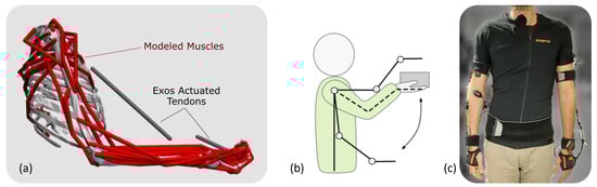
Figure 1.
(a) The musculoskeletal model, (b) the lifting task used for calibration experiments and simulation, (c) the experimental setup used for calibration of the model.
Arm kinematics were acquired using inertial measurement units (IMUs) provided by Xsens MVN Link (Xsens Technologies B.V., Enschede, The Netherlands). Subjects were equipped with 11 IMUs placed on their hands, forearms, upper arms, scapula, sternum, head, and pelvis, following the guidelines outlined in the Xsens MVN manual. IMU signals were sampled at 240 Hz for all participants, and data were collected using the associated MVN Analyze 2022.0.2 software (Xsens Technologies B.V., Enschede, The Netherlands). A representative subject wearing the sensors is shown in Figure 1c.
Simultaneously, the synchronized activities of targeted muscles were recorded through surface electromyography (sEMG) using a Bagnoli Desktop EMG system (Delsys, Natick, MA, USA). The integration of the IMU-based motion capture system and the EMG recording system was achieved through MVN Analyze software to ensure synchronization between kinematic and muscle activity data.
The specific muscles targeted in this study included the deltoid (anterior, medium, posterior), pectoralis major (sternal), flexor carpi ulnaris (FCU), flexor carpi radialis (FCR), extensor carpi ulnaris (ECU), extensor carpi radialis longus (ECRL), biceps brachii (short head), and triceps brachii (long head). Raw EMG data underwent post-processing, including band-pass filtering (30–450 Hz), full-wave rectification, and low-pass filtering (6 Hz), utilizing a zero-phase second-order Butterworth filter. To enable comparisons of muscle activities across different conditions, subjects, and simulated muscle activities, the post-processed EMG envelopes were normalized based on maximum voluntary contractions.
2.1.2. Musculoskeletal Model
Musculoskeletal simulations were conducted using OpenSim, a widely adopted open-source software in the realm of movement science [29,30]. In our study, we employed a customized unimanual upper extremity musculoskeletal model [31], implemented within the OpenSim environment [32]. This model [32] incorporates 7 degrees of freedom, encompassing shoulder elevation, elevation plane, shoulder rotation, elbow flexion, forearm rotation, wrist deviation, and wrist flexion. Additionally, it consists of 50 Hill-type muscle–tendon actuators representing the 32 muscles and muscle compartments that traverse the shoulder, elbow, forearm, and wrist joints.
For simulating the unimanual lifting of a hand-held weight, we modeled the load as a disk (height: 62.5 mm, radius: 40 mm) with a uniform density, rigidly attached to the hand within the model. To account for unmodeled passive components and potential muscle weaknesses, we introduced a set of Coordinate Actuators to the model’s coordinates, serving as reserve actuators. These actuators were configured to apply minor joint moments as needed to compensate for these factors.
The musculoskeletal simulations were customized to individual subjects using the experimental data we collected. These simulations encompassed three distinct conditions: simulations of unassisted subjects both with and without a 3 kg weight load (referred to as loaded and noload subjects, respectively), and simulations of assisted subjects engaged in lifting a 3 kg weight.
2.1.3. Musculoskeletal Simulation Workflow
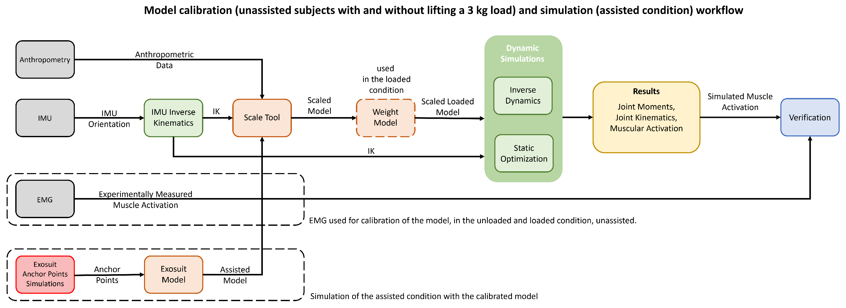
The simulation process, which is depicted in Figure 2, was initiated with the calculation of inverse kinematics, which relied on the IMU orientation data obtained from the experiments. We executed this step using the OpenSense toolkit [33] within OpenSim 4.4. For each participant and under each condition, we conducted three simulation trials. Within each trial, we utilized the IMU Placer and IMU Inverse Kinematics tools to produce joint kinematics.
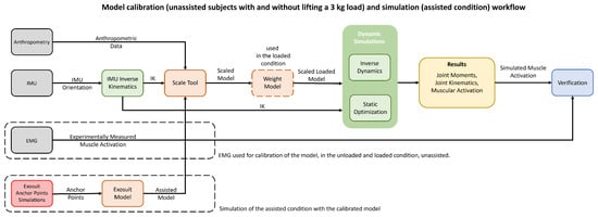
Figure 2.
Workflow scheme of the adopted models, summarizing the calibration phase, with the real user and IMU data in the no-load and loaded condition, and the simulation phase, including simulation with exoskeleton co-activation, and verification of the simulations with recorded EMG data.
The orientation of each IMU was assigned to its associated rigid body in the model, and then the set of IMU orientations was imported into OpenSense. Due to the unimanual upper extremity model, we only used the sternum and right arm IMU measurements for computation of the inverse kinematics, and the sternum served primarily as the base IMU for our model since the motion of the thorax was not of interest to us.
Using the IMU Placer Tool and the IMU calibration data, the fixed orientation of IMU frames in relation to the body segments of the posed model was calibrated. Due to the IMU Placer Tool assumption that the default poses of the model match the pose of the subject during calibration, the model’s default posture was manually altered to be aligned with the subject as closely as possible. Additionally, we provided three rotational degrees of freedom on the thorax body to achieve finer results between the experimental IMU orientation and virtual IMUs. The musculoskeletal model of a representative subject with calibrated virtual IMUs is demonstrated in Figure 3.
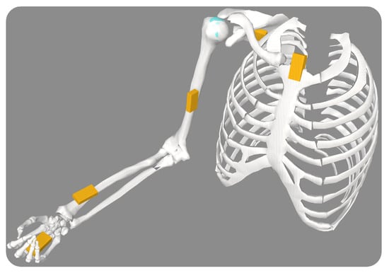
Figure 3.
The musculoskeletal model with calibrated virtual IMUs on each body segment.
Once the virtual IMUs’ offsets were calibrated, we employed the IMU Inverse Kinematics Tool. This tool enables us to determine joint angles that minimize the weighted squared difference between the experimentally measured IMU orientations and the virtual IMU orientations [33]. The weights assigned to each IMU were based on the reliability of their measurements and their significance in determining kinematics. Notably, we down-weighted the sternum IMU because the model did not account for thorax kinematics.
As the rigid body segment length has no influence on IMU-based inverse kinematics [33], the inverse kinematics of joints were computed without scaling the model. However, the inertial and musculotendinous features of the model will directly influence the dynamic simulations; hence, scaling the generic model is required to generate a subject-specific musculoskeletal model and, subsequently, subject-specific dynamic simulation results.
We did not employ optical motion capture equipment during the data-gathering phase; therefore, the standard approach of scaling the model using marker data is not applicable to our simulations. Along these lines, we relied on the manual scaling approach to generate a scaled model.
Given that the segments lengths of the generic model were consistent with the anthropometry data of a 50th percentile male described in [34], scaling of the segments would be possible by taking the same standard measurements from the subjects, as described in Gordon et al. [34]. Consequently, the lengths of the hand, forearm, upper arm, and clavicle bodies of each subject were measured, and then the required scale factor was calculated as a ratio between the length of the segment in the generic model to the measured subject.
These scale factors were incorporated into the OpenSim Scale Tool to scale each segment uniformly and generate the scaled musculoskeletal model. Each segment’s mass and inertial characteristics were also scaled by the product of its scale factor. After scaling, the mass of the segments was verified to be comparable to its estimated weight based on the subject mass [35].
Finally, the optimal fiber and tendon slack lengths of the generic model were scaled to retain their ratio across the scaled muscle path length, which concludes our scaling procedure.
We applied the OpenSim Static Optimization (SO) Tool to calculate the muscle activation and, subsequently, the forces required to generate the joint moments of the scaled model that tracked joint kinematics. Even though computed muscle control (CMC) is a common approach for producing muscle-driven simulations [18,20,21,29,32,36], the use of SO was preferred due to the complexity of the musculoskeletal model and, therefore, the time required by CMC for computation of each simulation.
Although the CMC approach takes into account a more realistic muscle model and muscular excitation, it has been shown that both static, CMC and dynamic optimization could provide comparable estimates of muscle forces during typical task performance [37,38]. The CMC would be considered a more appropriate tool to simulate rapid movements when activation and contraction dynamics play a significant role [38,39].
Considering that the objective of this study is to gain qualitative insight into the dynamics of muscle activation and the computational cost of the CMC, it was determined that SO was a more suitable technique to employ in this study.
As indicated in the OpenSim tutorial regarding the Static Optimization Tool, this tool utilizes the inverse kinematics solution of the model to address the equations of motion concerning joint torques, referred to as generalized forces in the model. These joint torques are controlled by the muscle activation-to-force dynamics, which, in turn, are limited by the constraints imposed by the force–length–velocity properties of the muscles, as outlined in Equation (1). This tool effectively solves muscle redundancy by minimizing a weighted sum of squared muscle activations and actuators, as delineated in Equation (2).
In these expressions, the variable N signifies the total count of muscles incorporated within the model. Each muscle’s activation at a given time step is represented by . Other parameters include , , , and , which, respectively, denote the maximum isometric force, length, shortening velocity, and the force–length–velocity surface associated with each muscle. Additionally, represents the moment arm of the muscle relative to the jth joint axis, while stands for the generalized force acting about the jth joint axis.
In Equation (2), the variable R denotes the count of reserve actuators present in the model. The term signifies the immediate torque exerted by the rth reserve actuators, while stands for the weight factor that scales the penalty associated with activating the rth reserve actuators [21]. These actuators are specifically designed to compensate for unaccounted dynamics and muscle weaknesses. Consequently, their weight costs, denoted as “optimal force”, were adjusted to significantly increase the cost of their recruitment in comparison to the muscles.
2.1.4. Modeling Exosuits and Simulating Assisted Subjects
The modeling of the wrist–elbow exosuit was achieved through the utilization of the PathActuator class, a feature provided by the OpenSim API. This class is specifically designed for the representation of massless actuators capable of applying tension along a specified path. It serves as a practical framework for simulating these actuators within the wrist–elbow exosuit, offering control over tension application and enabling controlled motion along the designated geometry. The geometry path of the actuators is defined by assigning the anchor points as the origin and insertion points of the actuator. The implemented model is depicted in Figure 1a.
Upon incorporating the assistive actuators into the model, the objective function of the static optimization is subjected to a modification, as expressed in Equation (3), wherein the assistive actuators are integrated into the function.
Much like the approach involving reserve actuators, the modified equation incorporates additional terms, namely and , which represent the immediate torque applied by the wrist and elbow exosuit actuators, respectively. Correspondingly, and denote the optimal force of the wrist and elbow exosuit actuators.
To enable the simulation of an ideal exosuit scenario, the optimal force values of both the elbow and wrist actuators were modified to 1000 N. This adjustment aims to significantly reduce the recruitment cost associated with the assistive actuators. This alteration encourages the optimization process to prioritize the utilization of the exosuit over muscular efforts when generating the desired joint moments.
The static optimization in both assisted and unassisted subjects while lifting a load (i.e., loaded subjects) employed the same kinematics while unassisted subjects without load (i.e., noload subjects) had different kinematics.
3. Exosuit Design
For the design of the exosuit, we considered three sizes of human arm and consequently of the suit. For each size, we computed the dynamics of the human arm and the interaction with the exosuit at the anchor points. From the analytical relation, we optimized the positioning of the anchoring point and we proposed a preliminary design for the elbow–wrist exosuit.
3.1. Modeling of the Arm with the Exosuit
The mass distribution of the human arm was based on [40]; thus, the arm, forearm, and hand masses were evaluated as a percentage of the overall body weight. In particular, the arm mass was 3.25%, the forearm mass was 1.87%, and the hand mass was equal to 0.65%. We chose 75 kg as a reference body weight. The body part lengths were set as in Table 1.

Table 1.
Lenght of the arm, forearm, and hand for the three modeled sizes.
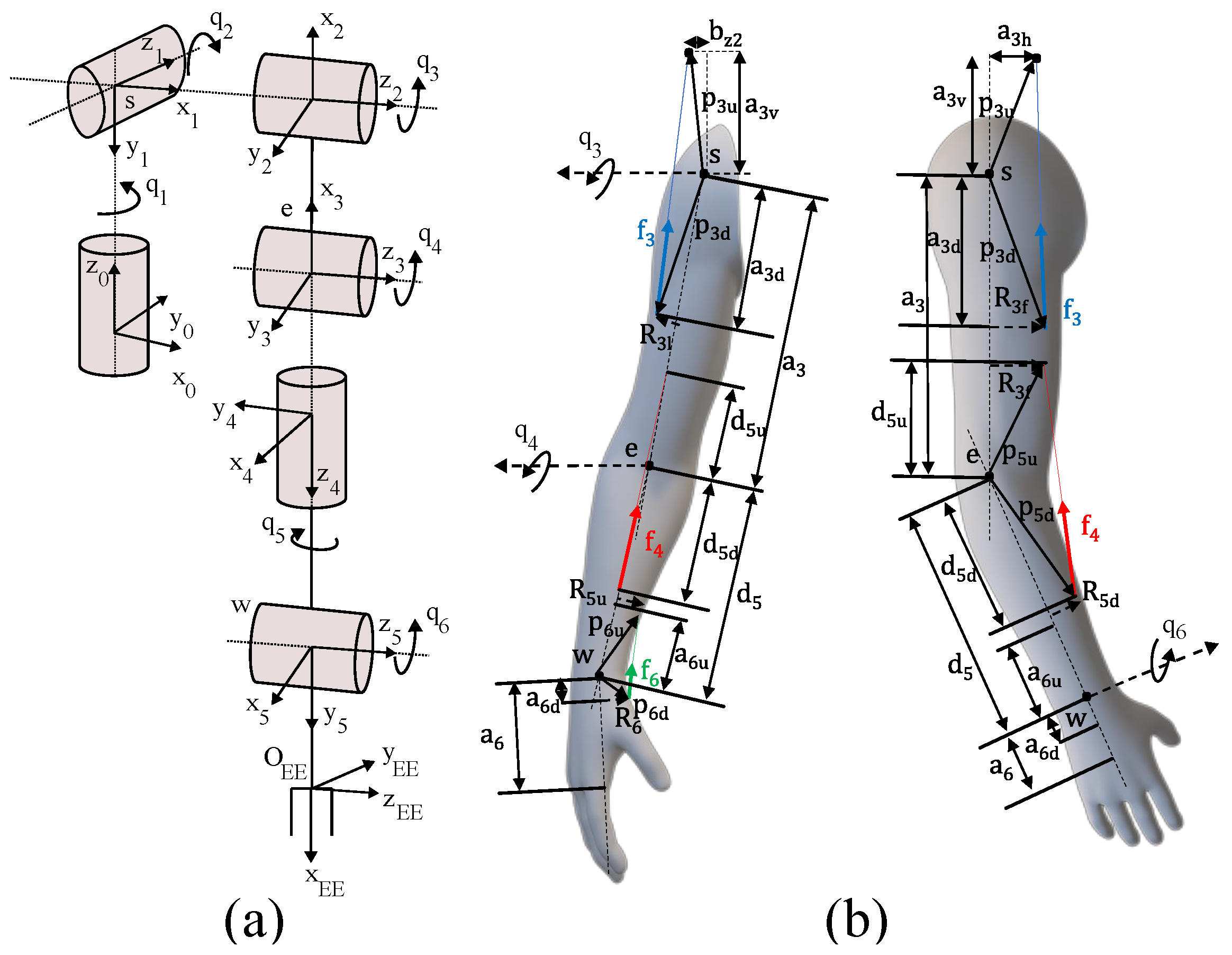
The design and optimization of the wrist–elbow exosuit started from the kinematic and dynamic modeling of the human arm and its interaction with the actuation units. The model takes into account three degrees of freedom (DoFs) for the shoulder, one DoF for the elbow, and two DoFs (flexion/extension and prono/supination) for the wrist. The modeled kinematic chain of the arm is shown in Figure 4a.

Figure 4.
Modeling of the human arm and its interaction with the exosuit. The kinematic chain used for the model (a), the geometrical parameters used for the generalized forces computation (b).
The dynamic equation describing the arm motion is recalled in Equation (4).
where , and are the vector of the joint angles, speed, and acceleration, respectively, are the linear inertial terms, are the centripetal and Coriolis terms, are the gravitational terms, is the effect of the external wrench on the joints, and is the joint torque vector.
For the actuation stage, we considered assisting only the flexion/extension of the three districts—shoulder, elbow, and wrist—and thus we considered the use of one motor per joint. Torque was applied to the human via Bowden cables from the motor pulley to an anchor point at the assisted body segment. For each actuator, we can identify a center of rotation and two anchor points:
- The first anchor point on the proximal segment where the actuator and the sheath of the Bowden cable are fixed.
- The second anchor point on the distal segment where the cable ends.
To optimize the tendon forces as a function of the anchor point locations, we determined the geometrical relation between them and the joint torques.
Figure 4b shows the geometric variables we used to derive the parametric equation of the forces exerted from the exosuit on the arm. The actuation force vector is constrained on the line connecting the two anchor points, identified by and , respectively.
The relation between the generalized forces that generate work on the Lagrangian coordinates and the actuator forces on the tendons is expressed by Equation (5)
where the vector components are related to the three chosen flexion/extension movements
where , ∈, the terms are scalars and represent the magnitude of the forces, represents transpose, and ∈ is the Jacobian matrix that relates the joint torque vector with the tendon forces applied by the actuators.
The matrix is obtained from the equation:
where is the generalized force that acts on the generalized coordinate ; is the application point of the force , that is, the j-th actuator force that makes work on the i-th generalized coordinate. is computed as:
where and are the position vectors represented in the Newtonian reference frame as shown in Figure 4. For the shoulder, elbow, and wrist flexion/extension case, the generalized forces become (for i ):
3.2. Exosuit Anchor Point Location Optimization
With the relation between the three tendon forces and the geometrical parameters of the anchor points, we built an optimization procedure to minimize the cost index defined in (10) for a human-like minimum jerk trajectory—as implemented in [11]—to simulate a smooth, human movement. We designed a cost index as one of the possible functions to minimize the amplitude of the tendons’ pulling force and to take into account its integral effect. We assumed that the efficiency of the transmission system remains constant throughout the exercise and that the friction losses are solely proportional to the cable tension.
We used genetic algorithms to find an optimal/sub-optimal solution due to the non-linearity and high complexity of the problem. For the genetic algorithm, we set the initial population of 50 individuals. Each one is characterized by its genes, which refer to optimization parameters. Moreover, each individual of the generation is evaluated by the cost function (Equation (10)), and then the next population is generated by using the operator. The and the were set to and , respectively. We set the maximum number of iterations equal to 100 × , whereas the between two iterations was set to . As a crossover function, we used the with the parameter equal to . Finally, the mutation strategy adopted was the due to the presence of constraints and the possibility of exploring the solution space with a random direction of the mutation process.
Before starting the optimization procedure, we set the values of the known parameters to m, m, = , = , = . Moreover, the physical limit of the parameters became a constraint for the optimization variable. The optimization converged by proving the parameters in Table 2.
Table 2.
Optimized parameters for the elbow and wrist for the three selected sizes.
As a result, the effect of decreasing parameter results in an increase in force and a decrease in . Moreover, the parameter tends to be equal to the upper limit, i.e., the distance between the wrist and the center of the hand. The parameter tends to be as small as possible and thus as close as possible to the wrist, while parameters and coincide with their own upper limits.
Lastly, it is convenient to have , , , and as large as possible.
The exosuit modeled and simulated in the following subsections was set up by using the results of the presented optimization procedure for a medium size suit.
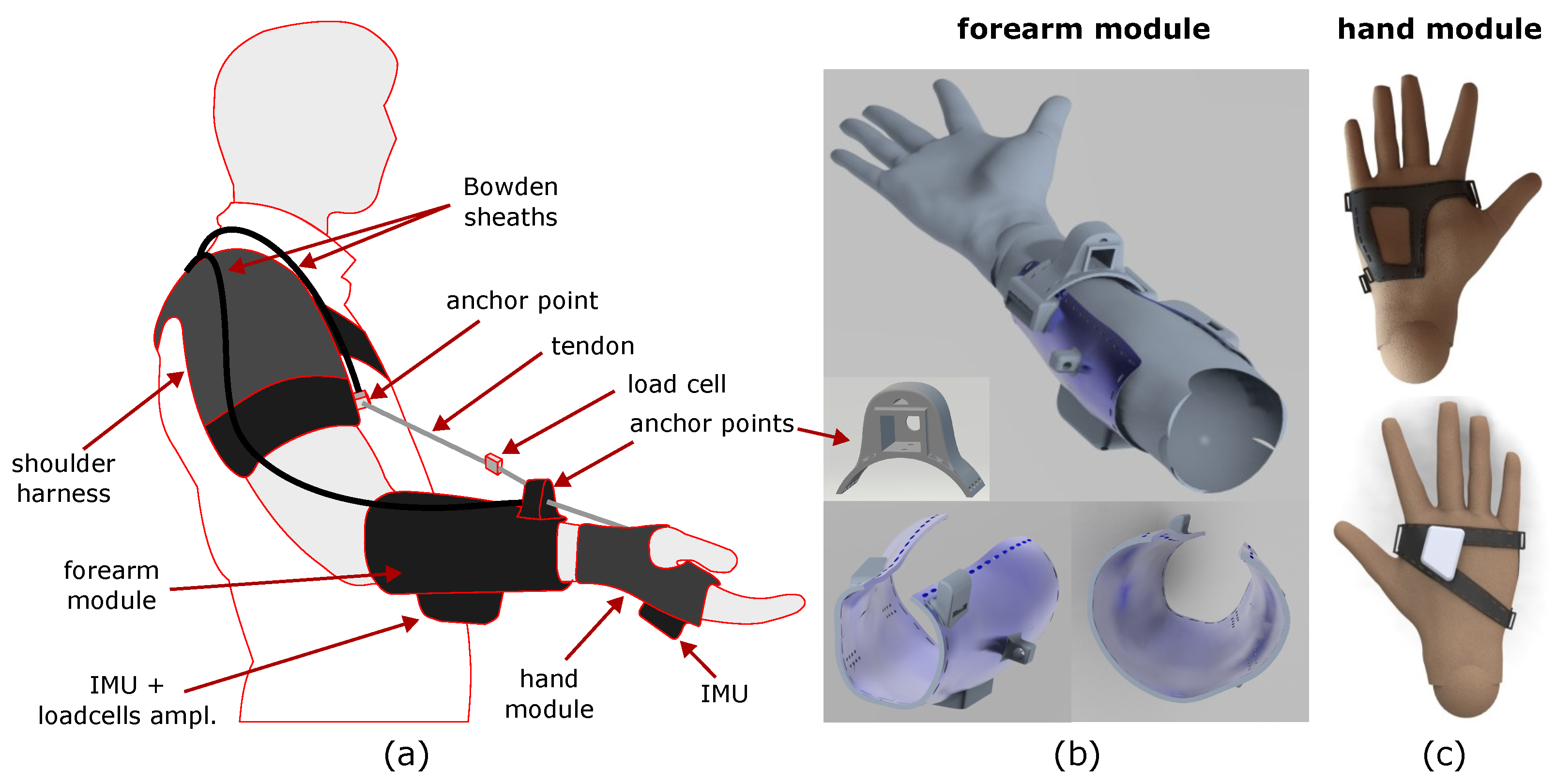
3.3. Exosuit Design
The design of the exosuit was conceived to merge soft and flexible materials—fabrics and plastic—to wrap around the human arm and transmit forces to its wearer’s skeletal structure. The proposed design comprises three main modules: the shoulder harness, the forearm module, and the hand glove (see Figure 5a). Each proximal module transmits forces to its next distal one through a tendon transmission; thus, when the tendons are tensioned, an assistive torque is delivered to the joint between the two modules. To efficiently apply the forces to the forearm and the hand, we stiffened the two fabric modules with a flexible 3D-printed ABS structure. This solution has already been proven to be effective for the wrist soft exosuit in [14]. In more detail, the forearm module (see Figure 5b) comprises a forearm band made of fabric with a plastic shell sewn on to it. The shell has an ergonomic shape that matches the 3D scan of the forearm of a mannequin with a height of 1.75 m The shell has a threefold purpose: it distributes the pressure due to interaction forces on a larger zone of the forearm, it makes the transmission of forces effective, and it hosts the anchor points and the compact embedded electronics for the local sensors. The anchor points on the forearm are located on a small 3D-printed arch that connects the two sides of the shell. The arch is sewn on to a band that can be tightened around the user’s forearm. The hand module (see Figure 5c) is composed of a glove with flexible and local reinforcements. The 3D-printed shell of the hand was conceived to be ergonomic and to not hinder hand closing/opening. An IMU is installed on the hand dorsum, from which data are retrieved via the embedded board on the forearm. The interaction forces between the exosuit and the user are collected by the compact load cells installed between the distal anchor points and the tendons. The proximal anchor point of the elbow joint is located on the shoulder harness at the level of the arm. Each tendon is wrapped around a pulley and is then routed in a Bowden sheath that is firmly connected between the proximal and distal anchor points.
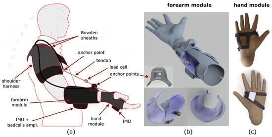
Figure 5.
Proposed design of the exosuit. Sketch of the whole exosuit (a), views of the 3D-printed forearm module (b), and views of the 3D-printed hand module (c).
4. Results and Discussion
4.1. Validation of Simulations
The OpenSim model adopted in this study underwent prior verification conducted by Holzbaur et al. [31] and Saul et al. [32]. Considering that no significant changes were made to the model for these simulations, it was not necessary to perform any further verification to support its use in our experiments.
The virtual IMUs tracked the orientation of the experimental IMUs, with the root mean square errors detailed in Table 3 for both the unloaded and loaded conditions. It is noteworthy that an error associated with the thorax IMU was anticipated and, accordingly, its impact on the inverse kinematics was significantly reduced through down-weighting. Given the reliance on IMU-based measurements and inverse kinematic calculations, as described in [33], we maintain that the computed kinematics remain sufficiently dependable, particularly considering that the primary findings of this study are of a qualitative nature.
Table 3.
Median and interquartile range (IQR) of the root mean square of the virtual and experimental IMUs’ orientation error.
The alignment between the recorded electromyography (EMG) data of the specified muscles and the simulated muscle activities exhibits a satisfactory timing consistency for the majority of the targeted muscles, as depicted in Figure A1, Figure A2 and Figure A3. Additionally, shifts in simulated muscle activities during the lifting of a load resemble analogous patterns observed in the majority of EMG measurements taken during the load-lifting task. This correspondence indicates the consistency between the simulated and observed muscle responses during load-related activities.
As both simulated muscle activities and EMG measurements of the muscles are prone to different errors [32,41,42], they should be compared in light of these error sources. First of all, it should be noted that recorded EMG signals are subject to delay, and this must be taken into account when comparing electromyography data with simulated activity data [42]. Second, since the EMG measurements were normalized using the voluntary maximum contractions of each subject, it was not expected that the amplitudes would be similar between simulation and EMG due to the inherent variability that is associated with this normalization. Instead, we expected to observe similar trends in the amplitude of muscle activities when comparing noload to loaded conditions. Further, the static optimization method computes the muscle activation under the assumption of inextensible tendons and does not take into account the contribution of the parallel elastic elements of the muscles, which can result in differences between simulation-based muscle activities and measured EMG data. Lastly, the kinematic tracking error results in arm motions that are slightly different to the motions of the arm during the experiments, which may also be a reason for the difference between the simulations and experiments.
The ratios of RMS and peak torque provided by reserve actuators to the net joint moment across degrees of freedom and simulations were 17.74% and 5.84%, respectively, for the noload condition, while the ratios were 2.54% and 9.71% for the loaded condition. These ratios for the assisted subjects were 0.075% and 0.28%, which is expected, as exosuit actuators provide the required torques to the joints of interest with a lower penalization cost.
Although most of these values are higher than the ratio recommended by Hicks et al. [42], the reserve actuators do not exceed the recommended torques by OpenSim. Although the ratio of the reserve actuator to the joint moment was high in the hand and wrist, a comparison of the muscle activities to EMG measurements demonstrated a similar onset and offset timing; additionally, further analyses of these reserve torques show that most of these torques are injected to satisfy the imposed constraints in the model. The kinematic uncertainty was another cause of the high ratio between the reserve torque and joint moments (e.g., a high wrist deviation would result in a small constraint violation and an injection of force via the wrist deviation ligament, which was compensated for by the torque provided by the reserve actuator of the wrist deviation coordinate). Considering the good agreement of timings between simulated muscular activities and EMG measurements, it was concluded that the contribution of the reserve actuators would not significantly affect the conclusions of this study.
4.2. Exosuit Performance
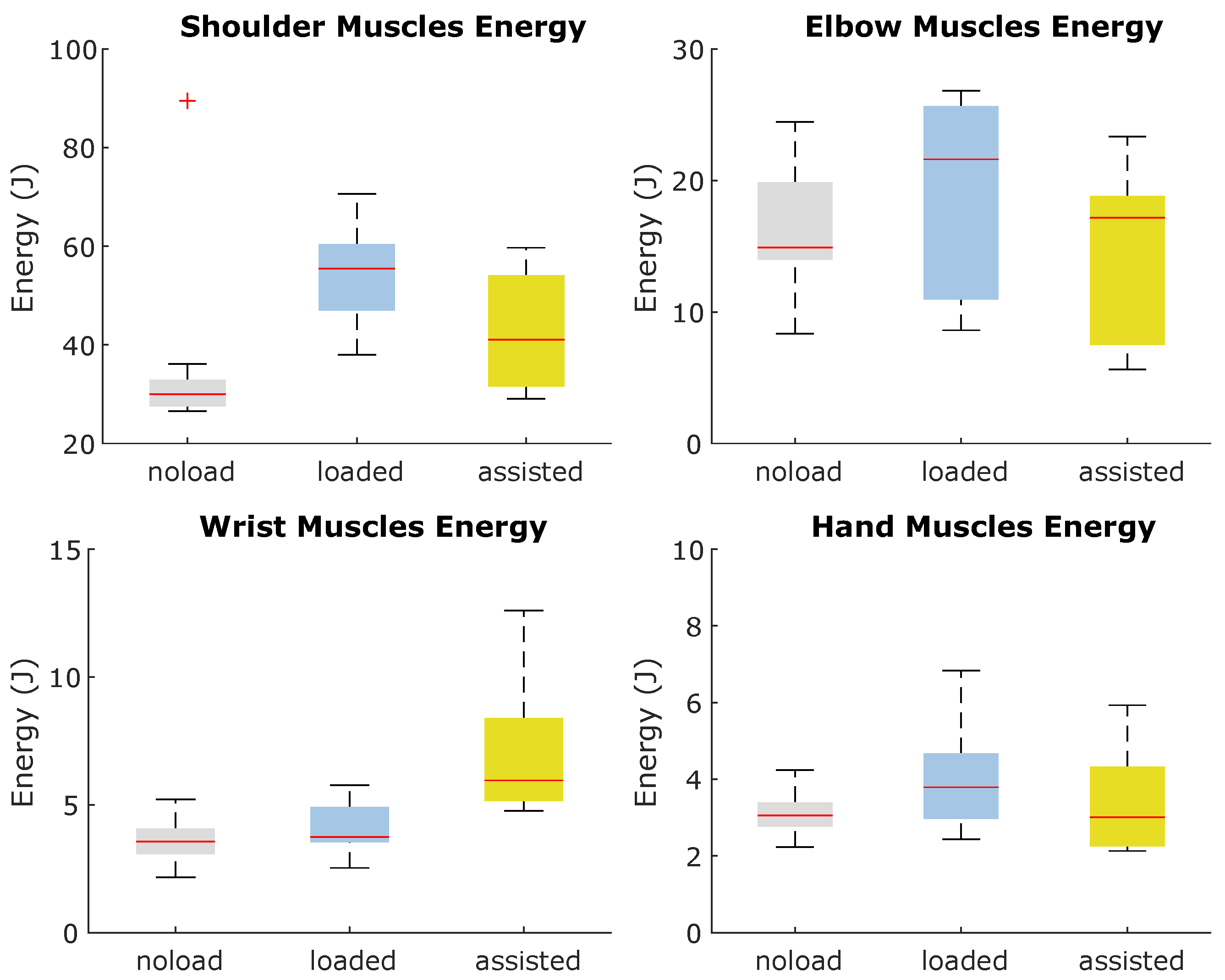
Through an evaluation of the cumulative energy expended by the muscles, it became evident that the elbow–wrist exosuit effectively reduces the overall energy expenditure of the arm during lifting activities. Further analysis of the muscular energy expenditure within each joint demonstrates the exosuit’s indirect support for shoulder joints while assisting the elbow and wrist. Moreover, the analysis reveals an increase in energy consumption for the muscles encircling the wrist joint due to the assistance torque provided to this joint, as visually presented in Figure 6. To optimize muscle energy expenditure across the entire arm muscle group, it may be advantageous to enhance the activity of select muscles, as the optimization process encompasses a set of muscles and actuators. Consequently, an increase in the activity of certain muscles and the associated higher energy expenditure within the wrist-contributing muscles can yield favorable optimization outcomes by reducing the overall energy consumption of the arm’s muscles. This behavior aligns with findings from simulation-based investigations involving assistive devices [18,20,21].

Figure 6.
Energy consumption of muscles contributing to joint motions during noload, loaded, and assisted conditions.
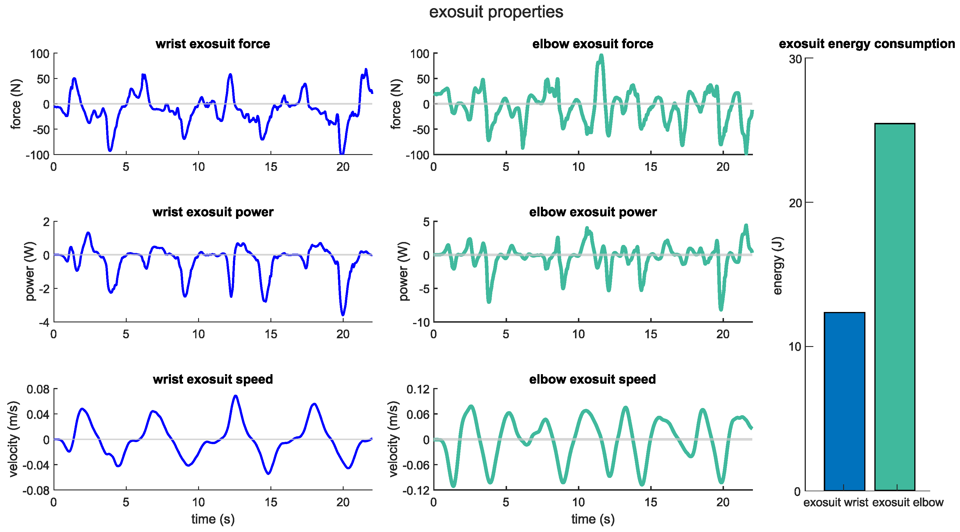
Although the elbow and wrist actuators exert a similar range of force with 266.50 ± 74.59 and 155.91 ± 68.06 N, the actuating speed range of the elbow actuator (0.17 ± 0.06 rad/s) is relatively higher than that of wrist actuator (0.09 ± 0.02 rad/s). In turn, this results in increased mechanical work on the elbow actuator and an enhanced level of assistance to the elbow joint. Quantitatively, the mean range of power delivered by the elbow actuator is 7.18 ± 4.66 W, while the wrist actuator delivers power with a mean range of 3.13 ± 1.41 W throughout arm motion. As can be seen from the representative profiles of the exosuit in Figure 7, the qualitative force, speed, and power profiles are in accordance with the quantitative analysis of the performance of the exosuit.
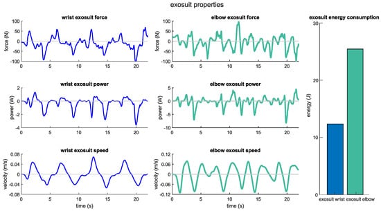
Figure 7.
Exosuit force, speed, and power profiles for a representative subject.
4.3. Lifting Load Effect on Arm Kinematics and Dynamics
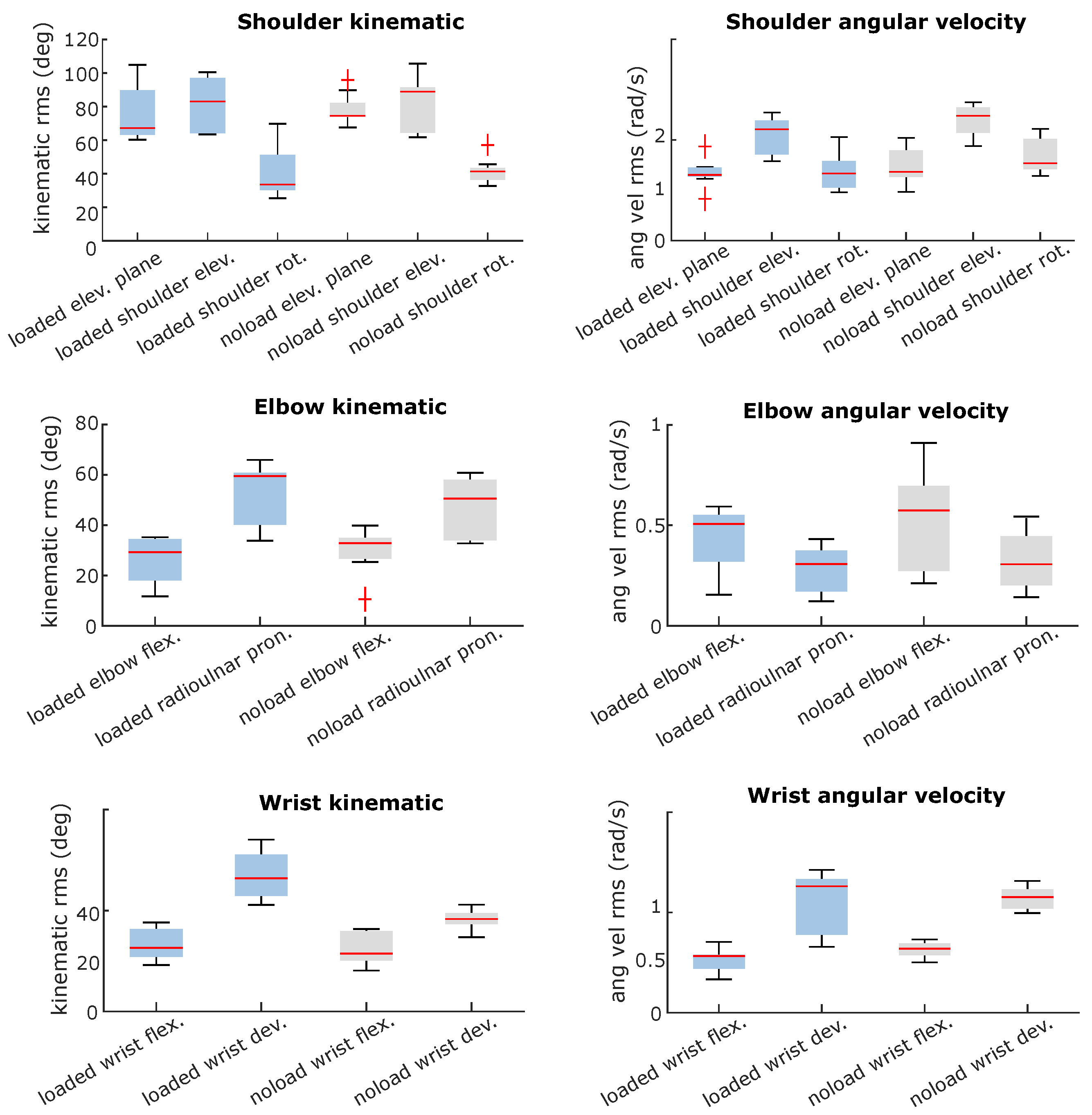
Since subjects were instructed to follow the visual cues during the experiments for both noload and loaded conditions, the range of motion of coordinates and the kinematics of the joints were similar during arm lifting with and without a load. While the joints are expected to have similar kinematics, the speeds of the joints differ considerably. Comparing the speed of joints indicates that shoulder elevation and rotation coordinates have slowed down by 0.49 ± 0.38 and 0.45 ± 1.07 rad/s. Furthermore, the wrist joint speed has been reduced by 0.39 ± 0.42 and 0.27 ± 0.26 rad/s in wrist flexion and deviation, respectively. Lastly, the elbow flexion and radioulnar pronation/supination speed reduced less than other joints by 0.25 ± 0.48 and 0.17 ± 0.20 rad/s, respectively. The root mean square of joint kinematics is shown in Figure 8 for lifting with and without a hand-held load which confirms the discussed results on the effect of lifting a load on the kinematics and speed of the arm. Additionally, the kinematic and speed profiles of joints are shown in Figure A4 and Figure A5 for a representative subject.
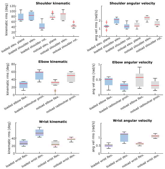
Figure 8.
Effect of load lifting on the kinematics of an arm.
It should be noted that there is significant within-subject variation while performing the task; as we only provided some visual landmarks during the experiments, this variation within the subjects while reaching the visual cues was expected.
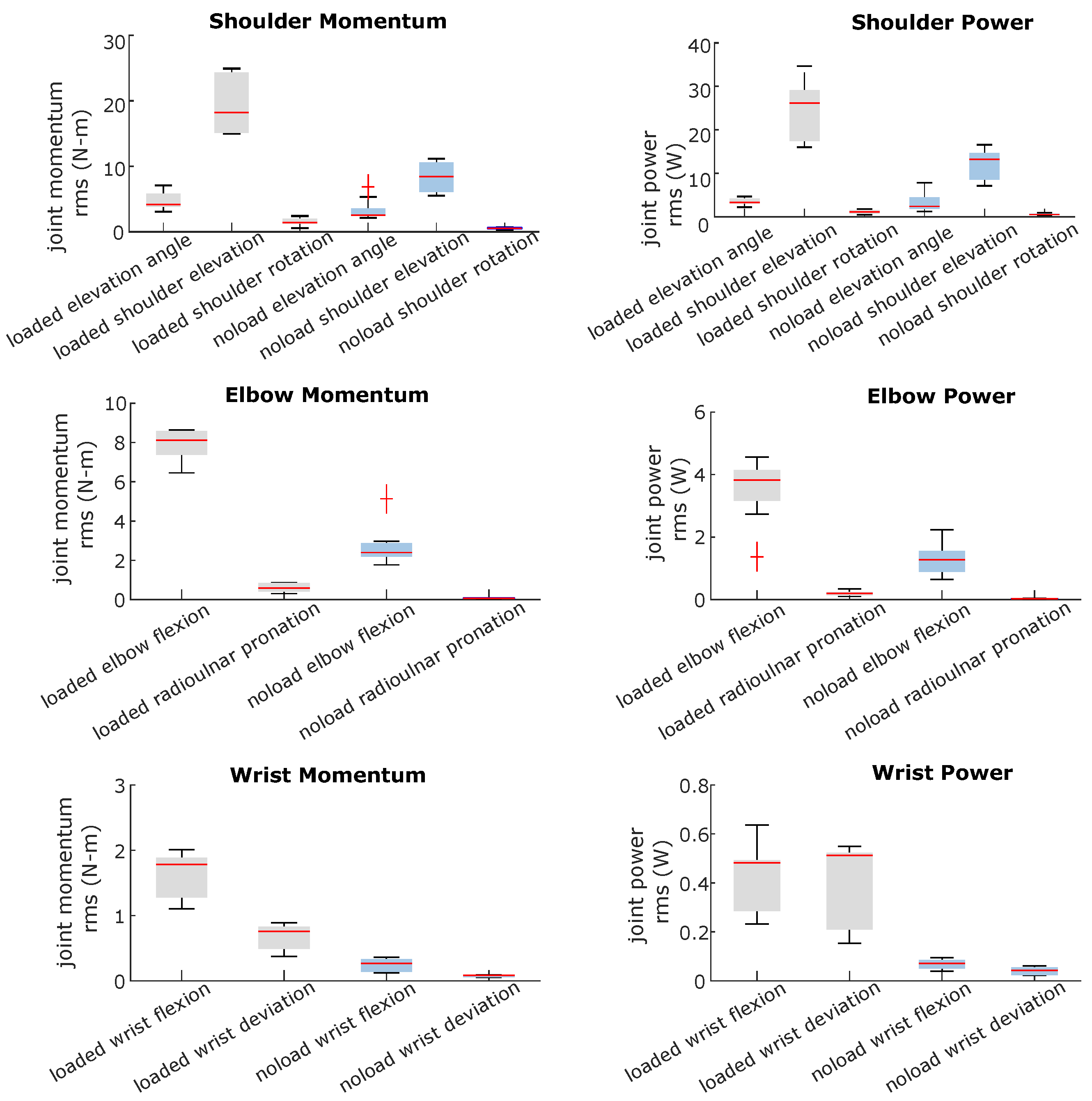
It would be intuitively expected that lifting a load, which is carried out primarily in the sagittal plane, would result in greater joint moments in both the elevation and flexion degrees of freedom. The comparison of the joint moments of subjects under two experimental conditions confirms that the results are consistent with expectations, as represented in Figure 9.
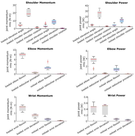
Figure 9.
Effect of load lifting on the arm joint momentum and power.
The shoulder joint moment was the most affected, with the highest effect on the shoulder elevation coordinate. The median moment for the elevation moment increased from 8.43 (IQR, 4.50) to 18.22 (IQR, 9.2) N-m. The moment of the elbow flexion was also significantly increased from a median of 2.39 (IQR, 0.68) to 8.11 (IQR, 1.2) N-m. Moreover, the moment of wrist flexion, which performed virtually no work during lifting without a load, was significantly increased from 0.26 (IQR, 0.19) to 1.78 (IQR, 0.60) N-m.
As a result of analyzing the kinematics of the task under two different loading conditions, along with the joint moments, it appears that the joints are required to perform significantly more mechanical work to lift a load than lifting an arm without the additional load, with the greatest increase in mechanical work occurring in the sagittal plane. Based on the results of the kinematics and dynamics of these joints, it can be concluded that effective assistance for the elbow and wrist joints can reduce the work that is required to be performed by muscles in these joints.
4.4. Exosuit and Lifting Load’s Effects on Muscle Activities
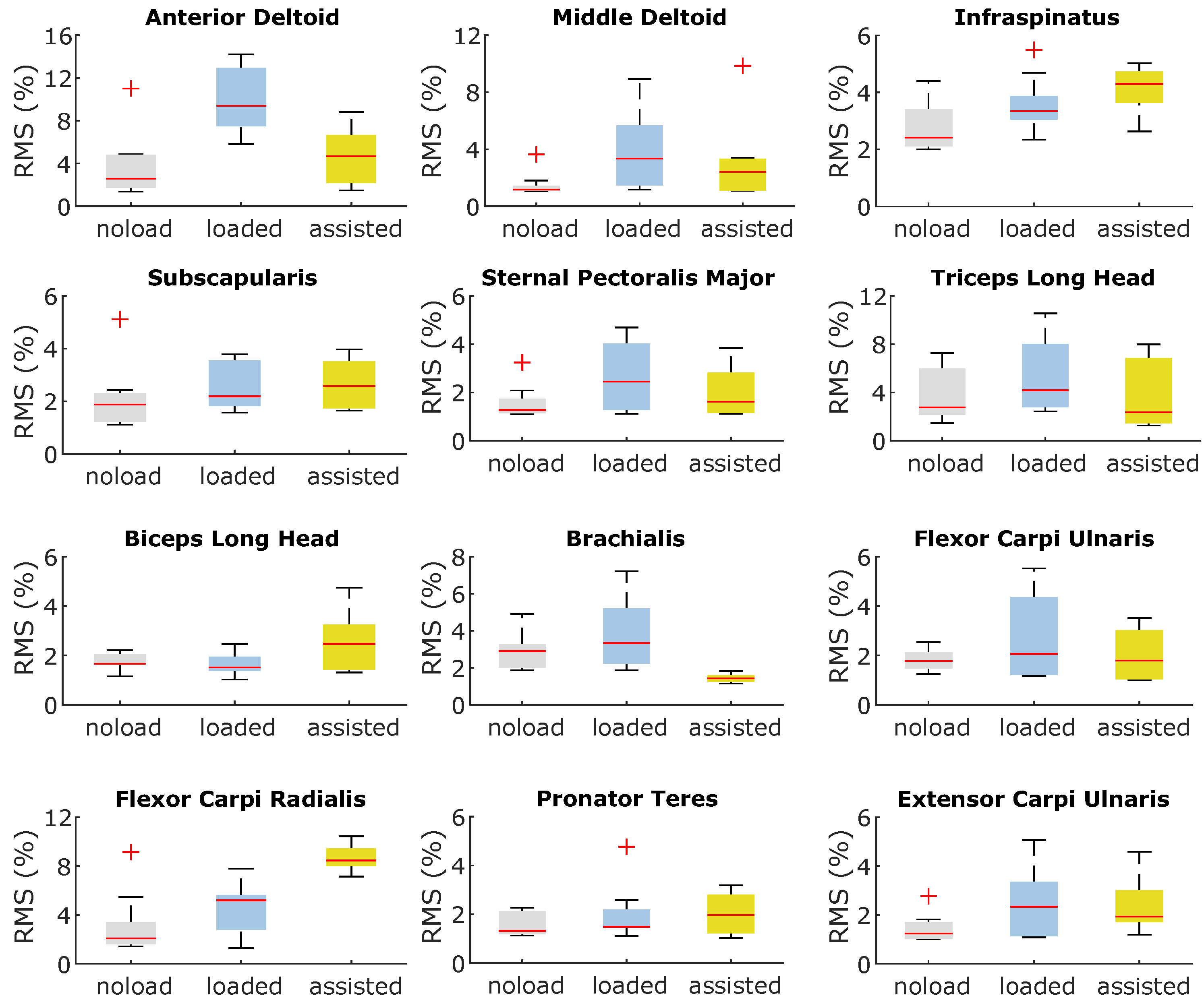
The elbow–wrist exosuit had a substantial impact on the muscle activity across various arm muscles. It is interesting to note that this effect extended beyond the muscles directly involved in elbow and wrist movements, affecting those associated with shoulder joint movements as well. Figure 10 visually depicts the muscle activation levels in selected arm muscles, with the data normalized as a percentage of their maximum activity (i.e., normalized to 1). These muscles were chosen based on their ability to generate force during the lifting task and their significant contribution to arm motion. Upon analysis of Figure 10, it is evident that lifting a load significantly alters the activation levels of these representative muscles throughout the arm. These findings suggest that shoulder muscles play a crucial role in compensating for the additional load during arm lifting.
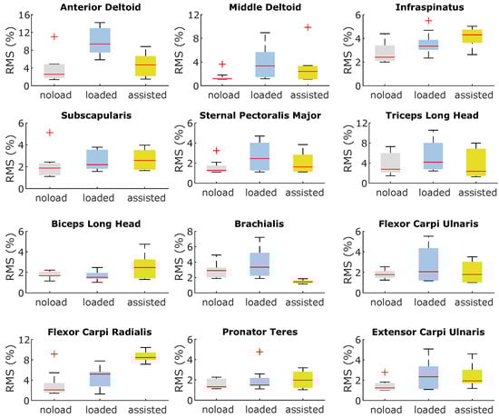
Figure 10.
Effect of load lifting and assistance from the wrist–elbow exosuit on the magnitude of activation of arm representative muscles.
The exosuit primarily impacts muscle activities related to the elbow and shoulder joints by reducing their activation levels, while simultaneously increasing the activities of muscles associated with the wrist joint. In particular, the flexor carpi radialis muscle, a major contributor to wrist movement, experiences a significant increase in activity. This heightened activity of the flexor carpi radialis, coupled with the relatively minor effect of assistance on other wrist muscles, results in an overall increase in energy consumption among the muscles responsible for wrist motion.
Furthermore, the assistance provided by the exosuit to the arm alters the coordination of muscles involved in shoulder movements, leading to a more economical recruitment of shoulder muscles during the task. Upon closer examination, it is evident that the activity of the deltoid muscle notably decreases, with the required force being compensated by heightened activity in more energy-efficient muscles such as the infraspinatus and subscapularis.
4.5. Discussion
An evaluation of the exosuit’s performance in providing assistance to the arm has shown that anchor points and therefore the moment arm available to the exosuit to provide moment play a significant role in the device’s effectiveness. It could be inferred from the results that although the anchor points were optimized for a model of the arm, an optimization framework in which both the exosuit and musculoskeletal model are integrated, as proposed in [18], could possibly lead to better results than optimizing the anchor points on the dynamic model of the arm. Specifically, under the constraints of the design, we believe that the anchor point for the wrist may need to be selected with greater care in order to provide more mechanical activity to the joint.
In accordance with our results, the exosuit has the potential to affect the activity of muscles that do not span the assisted degree of freedom, as shown in studies using assistive devices on lower limbs [18,20,21]. It is important, however, to carefully examine this behavior in a study based on experimental data relating to the upper limb.
According to the simulations, the shoulder is also responsible for bearing an important portion of the added load during arm lifting. There is, however, a significant challenge in designing a portable and lightweight shoulder exosuit for assistance, as discussed in [43]. The results of our study, however, suggest that we may be able to reduce the load related to muscles spanning the shoulder during load handling by using an elbow exosuit which, due to its nature, is easier to design and control.
4.6. Study Limitation
The results of simulation-based studies of exosuits need to be interpreted in light of their limitations. As one of the major limitations of this method, the kinematics of the assisted subjects are assumed to remain unchanged from the experimental data. During musculoskeletal simulations, static optimization cannot account for kinematic adaptation due to provided assistance; thus, it is assumed that unassisted and assisted subjects have the same joint moment and kinematics. Similarly, as OpenSim cannot support changes in the dynamic properties of subjects, the exosuit considered for musculoskeletal simulations is assumed to be massless.
It is important to note that the musculoskeletal model and simulation methods in general have certain inherent limitations, as discussed in [32,42], which should be taken into account when interpreting the conclusions drawn from this study.
In addition to the limitations of the musculoskeletal simulations, the experimental method employed in this study is also prone to errors that could impact the outcome of the simulations. As it was discussed earlier, the motion data of subjects were collected using an IMU-based motion capture system, and the kinematics were estimated based on OpenSense. Both IMU-based motion capture systems and estimations of the kinematics are prone to drift and error, which has already been acknowledged.
Although EMG recordings of the muscles that have been used to validate the muscusoleketal simulation are considered the ground truth for the validity of simulations, these measurements are highly sensitive to the placement of the sensor and other environmental effects and therefore, there is a high within-subject variation while measuring them.
Another point to be considered when interpreting the specific results of this work is the small size of the dataset used for calibrating the muscular activation model. Here, the focus of the study was to provide a comprehensive methodology for modeling and simulating the effect of an upper limb exosuit, and hence guiding its design parameters. To validate the specific results obtained in the simulation, a larger dataset is needed to meet the statistical power requirements [44]. Therefore, we used the obtained simulation results to qualitatively evaluate the effect of the exosuit on the musculoskeletal model of the arm and still showed interesting trends in the adopted design solution that were not obvious before.
5. Conclusions
This work presented a framework for the design and simulation of upper limb exosuits, covering all the developmental steps from modeling to optimization and simulation. Although focused on the design of an elbow–wrist exosuit, this framework represents a comprehensive methodology suitable for the design and simulation of other upper-limb-actuated exosuits. The complexity of the upper limb musculoskeletal system is here addressed both through a kinematic model, developed to design and optimize the exosuit layout, and through a complex musculoskeletal model of the upper limbs, developed to simulate device operation and its impact on the muscular activation of the user. Taking into account such a higher level of complexity of the upper limbs is the main advantage of this method with respect to other works adopting a simplified model depending on the actuated DOFs of the developed device.
The proposed framework can be generalized to other soft exoskeleton designs, even though we studied a wrist–elbow exosuit as a case study to contextualize the design process. Different designs can involve other segments (i.e., the shoulder) and in particular other assisted tasks, therefore changing the optimization and the load simulation results. In the developed method, the first step is the implementation of the analytical kinematic model of the arm, which can be transferred to the design of other upper limb exoskeletons, and the definition of the actuated joints and target trajectories. With the proposed approach, optimized anchor points of the soft exoskeleton were found. In the scope of the presented load-lifting task, the minimum jerk trajectory was adopted as the cost function criterion. Then, a musculoskeletal model was developed to simulate the effects of the exosuit on the user, considering all the different muscle units affecting the shoulder, elbow, and wrist. The purpose of this method is to obtain a well-calibrated and comprehensive musculoskeletal model of the user for the given task and then to simulate the effect of the exoskeleton before its actual implementation. The calibration experimental procedure has to be performed based on the desired task, although it is usable for different exoskeleton designs and anchor point optimization procedures. In order to better simulate real muscular activation, the calibration procedure uses experimental EMG and IMU data. Then, the final simulations with the musculoskeletal model can evaluate the effects of the exosuit activation at the level of the different muscle units, and the results can be compared with the unassisted condition. Interestingly, it emerges that not only obvious body segments and muscle units are affected by the exoskeleton activation, but also muscle units in other body districts (i.e., the shoulder) and on other dimensional axes than the planar task trajectories. These effects would not emerge through a simplified simulation reduced to the spatial and joint dimensions of the task. While on the one hand, the obtained model provides interesting insights into the effect of exoskeleton assistance and allows for evaluations at the design stage before prototype implementation, on the other hand, the results have to be considered from a qualitative perspective. Due to the complexity of the model, calibration, and other estimated factors, it is not expected that the model will resemble the precise quantitative behavior of the final prototype.
Together with the optimized layout of the anchor points, we provide a possible implementation of an exosuit at the level of CAD design in order to contextualize the approach within a real use case and its possible implementation. Further development in this direction includes testing a working prototype in order to compare experimental data with simulations. While it is unreasonable to expect a close matching between the results of musculoskeletal simulations and data collected from human-in-the-loop evaluations due to a number of limitations intrinsic to a complex simulation process as discussed above, the use of a more refined model and calibration can reduce this gap. The presented musculoskeletal simulation method has the considerable advantages of providing design guidelines and capturing trends, allowing for a systematic analysis of the consequences of various design decisions before their real-world implementation.
Author Contributions
Conceptualization, A.K.B., D.C., A.F. and D.L.; methodology, A.K.B., D.C., A.F. and D.L.; software, A.K.B. and D.C.; validation, A.K.B. and D.C.; formal analysis, A.K.B., D.C. and D.L.; investigation, A.K.B., D.C., A.F. and D.L.; resources A.F. and D.L.; data curation, A.K.B., D.C. and D.L.; writing—original draft preparation, A.K.B., D.C. and D.L.; writing—review and editing, A.K.B., D.C., A.F. and D.L.; visualization, A.K.B., D.C. and D.L.; supervision, D.C. and A.F.; project administration A.F.; funding acquisition, A.F. All authors have read and agreed to the published version of the manuscript.
Funding
This research was funded by project SUN, funded from the European Union’s Horizon Europe research and innovation program under grant agreement No 101092612.
Institutional Review Board Statement
This study was approved by the Board of Ethics of the Scuola Superiore Sant’Anna of Pisa, Italy on 26 March 2021 https://www.santannapisa.it/en/university/board-ethics, ID 152021.
Informed Consent Statement
Informed consent was obtained from all subjects involved in the study.
Data Availability Statement
The raw data supporting the conclusion of this article can be made available by the authors upon request.
Acknowledgments
We thank Edoardo Corsi for their precious help in the modeling of the human arm and for the design of the anchor point optimization procedure.
Conflicts of Interest
The authors declare that the research was conducted in the absence of any commercial or financial relationships that could be construed as potential conflicts of interest.
Appendix A. Simulated Muscle Activities and Measured Electromyography of a Representative Subject under noload and loaded Conditions
The figures presented herein illustrate a comparative analysis between the simulated muscle activities and the electromyographic (EMG) data obtained experimentally for the targeted muscles. These figures aim to compare the timing of muscle activations between the measured EMG data and the simulated muscles. Additionally, the figures compare the changes in muscular activities between no-load and loaded conditions for both EMG and simulated muscle activities.
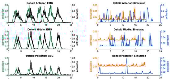
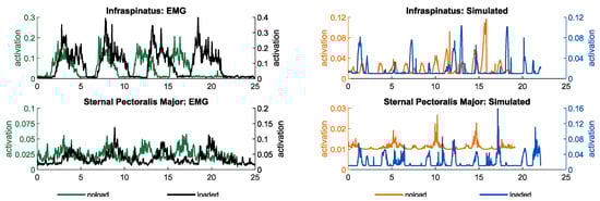
Figure A1.
Simulated muscle activities and measured electromyography of muscles contributing to shoulder motion in noload and loaded conditions.
Figure A1.
Simulated muscle activities and measured electromyography of muscles contributing to shoulder motion in noload and loaded conditions.
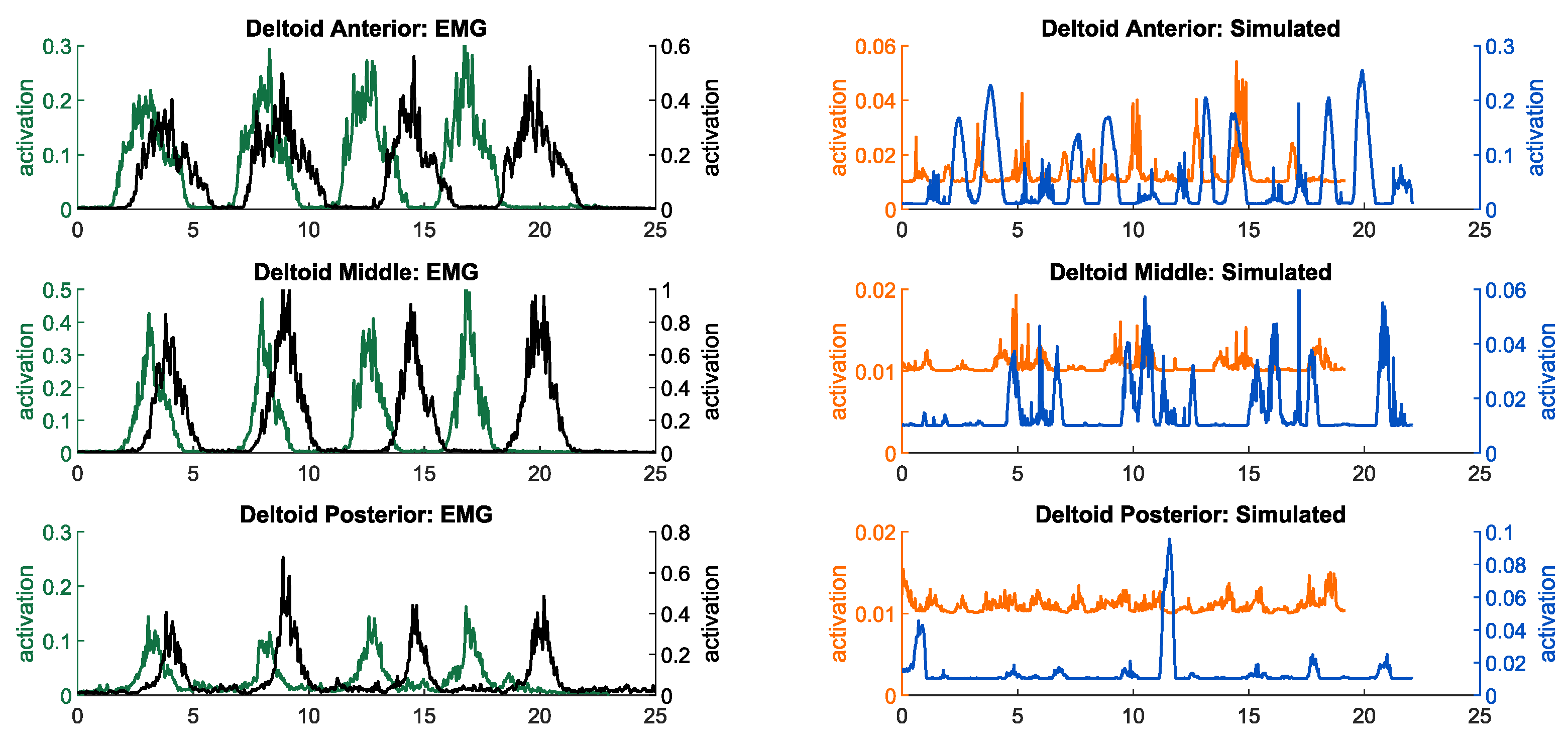

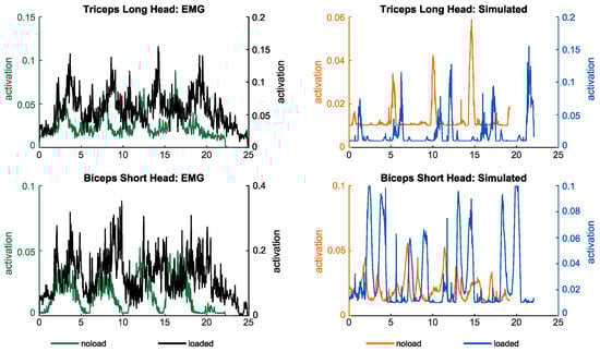
Figure A2.
Simulated muscle activities and measured electromyography of muscles contributing to elbow and radioulnar motions in noload and loaded conditions.
Figure A2.
Simulated muscle activities and measured electromyography of muscles contributing to elbow and radioulnar motions in noload and loaded conditions.

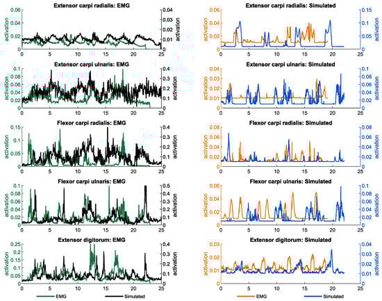
Figure A3.
Simulated muscle activities and measured electromyography of muscles contributing to wrist motion in noload and loaded conditions.
Figure A3.
Simulated muscle activities and measured electromyography of muscles contributing to wrist motion in noload and loaded conditions.
Appendix B. Kinematic and Speed Profiles of a Representative Subject’s Joints under noload and loaded Conditions
The following figures illustrate the kinematic and speed profiles of upper limb joints for a representative subject during arm lifting, with and without the additional load of holding a weight in their hand. These figures aim to offer insight into the kinematic variations during arm lifting under different load conditions. Specifically, they demonstrate how the kinematics of a representative subject differ between the two loading conditions.
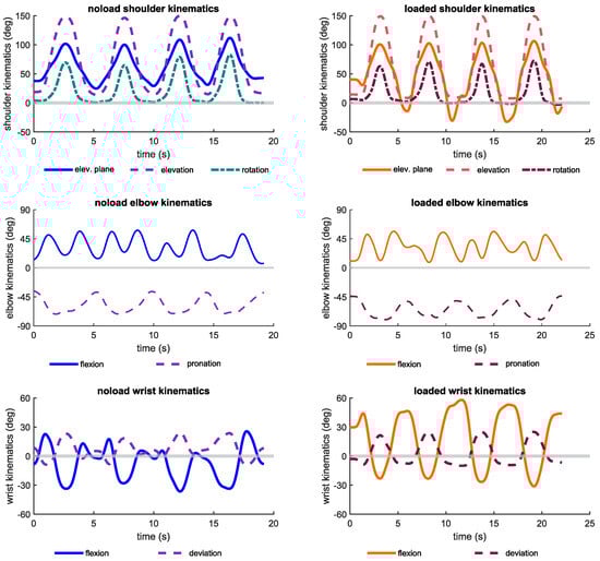
Figure A4.
Kinematic profiles of shoulder, elbow, and wrist joints during noload and loaded conditions.
Figure A4.
Kinematic profiles of shoulder, elbow, and wrist joints during noload and loaded conditions.
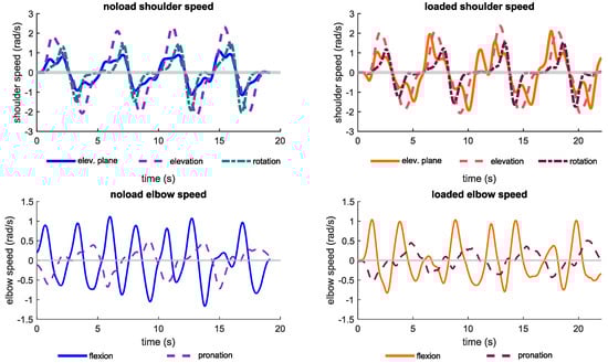
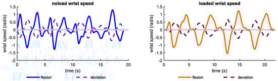
Figure A5.
Speed profiles of shoulder, elbow, and wrist joints during noload and loaded conditions.
Figure A5.
Speed profiles of shoulder, elbow, and wrist joints during noload and loaded conditions.
References
- Gull, M.A.; Bai, S.; Bak, T. A review on design of upper limb exoskeletons. Robotics 2020, 9, 16. [Google Scholar] [CrossRef]
- van Ommeren, A.L.; Smulders, L.C.; Prange-Lasonder, G.B.; Buurke, J.H.; Veltink, P.H.; Rietman, J.S. Assistive technology for the upper extremities after stroke: Systematic review of users’ needs. JMIR Rehabil. Assist. Technol. 2018, 5, e10510. [Google Scholar] [CrossRef] [PubMed]
- Xiloyannis, M.; Alicea, R.; Georgarakis, A.M.; Haufe, F.L.; Wolf, P.; Masia, L.; Riener, R. Soft robotic suits: State of the art, core technologies, and open challenges. IEEE Trans. Robot. 2021, 38, 1343–1362. [Google Scholar] [CrossRef]
- Simpson, C.; Huerta, B.; Sketch, S.; Lansberg, M.; Hawkes, E.; Okamura, A. Upper extremity exomuscle for shoulder abduction support. IEEE Trans. Med. Robot. Bionics 2020, 2, 474–484. [Google Scholar] [CrossRef]
- O’Neill, C.T.; Phipps, N.S.; Cappello, L.; Paganoni, S.; Walsh, C.J. A soft wearable robot for the shoulder: Design, characterization, and preliminary testing. In Proceedings of the 2017 International Conference on Rehabilitation Robotics (ICORR), London, UK, 17–20 July 2017; IEEE: Piscataway, NJ, USA, 2017; pp. 1672–1678. [Google Scholar]
- Georgarakis, A.M.; Xiloyannis, M.; Wolf, P.; Riener, R. A textile exomuscle that assists the shoulder during functional movements for everyday life. Nat. Mach. Intell. 2022, 4, 574–582. [Google Scholar] [CrossRef]
- Lessard, S.; Pansodtee, P.; Robbins, A.; Trombadore, J.M.; Kurniawan, S.; Teodorescu, M. A soft exosuit for flexible upper-extremity rehabilitation. IEEE Trans. Neural Syst. Rehabil. Eng. 2018, 26, 1604–1617. [Google Scholar] [CrossRef] [PubMed]
- O’Neill, C.; Proietti, T.; Nuckols, K.; Clarke, M.E.; Hohimer, C.J.; Cloutier, A.; Lin, D.J.; Walsh, C.J. Inflatable soft wearable robot for reducing therapist fatigue during upper extremity rehabilitation in severe stroke. IEEE Robot. Autom. Lett. 2020, 5, 3899–3906. [Google Scholar] [CrossRef]
- Li, N.; Yang, T.; Yu, P.; Chang, J.; Zhao, L.; Zhao, X.; Elhajj, I.H.; Xi, N.; Liu, L. Bio-inspired upper limb soft exoskeleton to reduce stroke-induced complications. Bioinspiration Biomim. 2018, 13, 066001. [Google Scholar] [CrossRef]
- Proietti, T.; O’Neill, C.; Gerez, L.; Cole, T.; Mendelowitz, S.; Nuckols, K.; Hohimer, C.; Lin, D.; Paganoni, S.; Walsh, C. Restoring arm function with a soft robotic wearable for individuals with amyotrophic lateral sclerosis. Sci. Transl. Med. 2023, 15, eadd1504. [Google Scholar] [CrossRef] [PubMed]
- Xiloyannis, M.; Chiaradia, D.; Frisoli, A.; Masia, L. Physiological and kinematic effects of a soft exosuit on arm movements. J. Neuroeng. Rehabil. 2019, 16, 1–15. [Google Scholar] [CrossRef]
- Thalman, C.M.; Lam, Q.P.; Nguyen, P.H.; Sridar, S.; Polygerinos, P. A novel soft elbow exosuit to supplement bicep lifting capacity. In Proceedings of the 2018 IEEE/RSJ International Conference on Intelligent Robots and Systems (IROS), Madrid, Spain, 1–5 October 2018; IEEE: Piscataway, NJ, USA, 2018; pp. 6965–6971. [Google Scholar]
- Nassour, J.; Zhao, G.; Grimmer, M. Soft pneumatic elbow exoskeleton reduces the muscle activity, metabolic cost and fatigue during holding and carrying of loads. Sci. Rep. 2021, 11, 12556. [Google Scholar] [CrossRef] [PubMed]
- Chiaradia, D.; Tiseni, L.; Xiloyannis, M.; Solazzi, M.; Masia, L.; Frisoli, A. An assistive soft wrist exosuit for flexion movements with an ergonomic reinforced glove. Front. Robot. AI 2021, 7, 595862. [Google Scholar] [CrossRef] [PubMed]
- Choi, H.; Kang, B.B.; Jung, B.K.; Cho, K.J. Exo-wrist: A soft tendon-driven wrist-wearable robot with active anchor for dart-throwing motion in hemiplegic patients. IEEE Robot. Autom. Lett. 2019, 4, 4499–4506. [Google Scholar] [CrossRef]
- Nam, C.; Rong, W.; Li, W.; Cheung, C.; Ngai, W.; Cheung, T.; Pang, M.; Li, L.; Hu, J.; Wai, H.; et al. An exoneuromusculoskeleton for self-help upper limb rehabilitation after stroke. Soft Robot. 2022, 9, 14–35. [Google Scholar] [CrossRef] [PubMed]
- Proietti, T.; O’Neill, C.; Hohimer, C.J.; Nuckols, K.; Clarke, M.E.; Zhou, Y.M.; Lin, D.J.; Walsh, C.J. Sensing and control of a multi-joint soft wearable robot for upper-limb assistance and rehabilitation. IEEE Robot. Autom. Lett. 2021, 6, 2381–2388. [Google Scholar] [CrossRef]
- KhalilianMotamed Bonab, A. Simulation Based Optimal Design of Exoskeletons to Reduce Metabolic Cost and Improve Energy Efficiency. Master’s Thesis, Sabanci University, Istanbul, Turkiye, 2021. [Google Scholar]
- Aftabi, H.; Nasiri, R.; Ahmadabadi, M.N. Simulation-based biomechanical assessment of unpowered exoskeletons for running. Sci. Rep. 2021, 11, 11846. [Google Scholar] [CrossRef] [PubMed]
- Dembia, C.L.; Silder, A.; Uchida, T.K.; Hicks, J.L.; Delp, S.L. Simulating ideal assistive devices to reduce the metabolic cost of walking with heavy loads. PLoS ONE 2017, 12, e0180320. [Google Scholar] [CrossRef] [PubMed]
- Uchida, T.K.; Seth, A.; Pouya, S.; Dembia, C.L.; Hicks, J.L.; Delp, S.L. Simulating ideal assistive devices to reduce the metabolic cost of running. PLoS ONE 2016, 11, e0163417. [Google Scholar] [CrossRef] [PubMed]
- Joshi, S.; Beck, I.; Seth, A.; Della Santina, C. Minimalistic Soft Exosuit for Assisting the Shoulder via Biomechanics-Aware Optimization. In Proceedings of the 2022 IEEE-RAS 21st International Conference on Humanoid Robots (Humanoids), Ginowan, Japan, 28–30 November 2022; IEEE: Piscataway, NJ, USA, 2022; pp. 667–673. [Google Scholar]
- Vo, T.E.; Jhangiani, R.; Robbins, A.; Elor, A. Designing user-specific soft robotic wearable muscular interfaces with iterative simulation. In Proceedings of the 2020 IEEE International Conference on Smart Computing (SMARTCOMP), Bologna, Italy, 14–17 September 2020; IEEE: Piscataway, NJ, USA, 2020; pp. 253–255. [Google Scholar]
- Lamers, E.P.; Zelik, K.E. Design, modeling, and demonstration of a new dual-mode back-assist exosuit with extension mechanism. Wearable Technol. 2021, 2, e1. [Google Scholar] [CrossRef]
- Sambhav, R.; Jena, S.; Chatterjee, A.; Bhasin, S.; Santapuri, S.; Kumar, L.; Muthukrishnan, S.P.; Roy, S. An integrated dynamic closed loop simulation platform for elbow flexion augmentation using an upper limb exosuit model. Front. Robot. AI 2022, 9, 768841. [Google Scholar] [CrossRef]
- Bardi, E.; Ambrosini, E.; Pirelli, A.; Pedrocchi, A.; Braghin, F.; Covarrubias, M.; Gandolla, M. Upper limb exosuit cable routing optimization. In Proceedings of the 2022 International Conference on Rehabilitation Robotics (ICORR), Rotterdam, The Netherlands, 25–29 July 2022; IEEE: Piscataway, NJ, USA, 2022; pp. 1–6. [Google Scholar]
- Noei, V.; Lakany, H. Analysis of movement of an elbow joint with a wearable robotic exoskeleton Using OpenSim software. In Proceedings of the 2022 44th Annual International Conference of the IEEE Engineering in Medicine & Biology Society (EMBC), Glasgow, UK, 11–15 July 2022; pp. 4342–4345. [Google Scholar] [CrossRef]
- Bonab, A.K.; Leonardis, D.; Frisoli, A.; Chiaradia, D. Modeling, Optimization, and Musculoskeletal Simulation of Elbow-Wrist Exosuit. In Proceedings of the 2023 21st International Conference on Advanced Robotics (ICAR), Abu Dhabi, United Arab Emirates, 5–8 December 2023; pp. 460–466. [Google Scholar] [CrossRef]
- Seth, A.; Hicks, J.L.; Uchida, T.K.; Habib, A.; Dembia, C.L.; Dunne, J.J.; Ong, C.F.; DeMers, M.S.; Rajagopal, A.; Millard, M.; et al. OpenSim: Simulating musculoskeletal dynamics and neuromuscular control to study human and animal movement. PLoS Comput. Biol. 2018, 14, e1006223. [Google Scholar] [CrossRef] [PubMed]
- Delp, S.L.; Anderson, F.C.; Arnold, A.S.; Loan, P.; Habib, A.; John, C.T.; Guendelman, E.; Thelen, D.G. OpenSim: Open-source software to create and analyze dynamic simulations of movement. IEEE Trans. Biomed. Eng. 2007, 54, 1940–1950. [Google Scholar] [CrossRef] [PubMed]
- Holzbaur, K.R.; Murray, W.M.; Delp, S.L. A model of the upper extremity for simulating musculoskeletal surgery and analyzing neuromuscular control. Ann. Biomed. Eng. 2005, 33, 829–840. [Google Scholar] [CrossRef] [PubMed]
- Saul, K.R.; Hu, X.; Goehler, C.M.; Vidt, M.E.; Daly, M.; Velisar, A.; Murray, W.M. Benchmarking of dynamic simulation predictions in two software platforms using an upper limb musculoskeletal model. Comput. Methods Biomech. Biomed. Eng. 2015, 18, 1445–1458. [Google Scholar] [CrossRef] [PubMed]
- Al Borno, M.; O’Day, J.; Ibarra, V.; Dunne, J.; Seth, A.; Habib, A.; Ong, C.; Hicks, J.; Uhlrich, S.; Delp, S. OpenSense: An open-source toolbox for inertial-measurement-unit-based measurement of lower extremity kinematics over long durations. J. Neuroeng. Rehabil. 2022, 19, 22. [Google Scholar] [CrossRef] [PubMed]
- Gordon, C.C.; Churchill, T.; Clauser, C.E.; Bradtmiller, B.; McConville, J.T. Anthropometric Survey of US Army Personnel: Methods and Summary Atatistics 1988. Technical Report; Anthropology Research Project Inc.: Yellow Springs, OH, USA, 1989. [Google Scholar]
- Winter, D.A. Biomechanics and Motor Control of Human Movement; John Wiley & Sons: Hoboken, NJ, USA, 2009. [Google Scholar]
- McFarland, D.C.; McCain, E.M.; Poppo, M.N.; Saul, K.R. Spatial dependency of glenohumeral joint stability during dynamic unimanual and bimanual pushing and pulling. J. Biomech. Eng. 2019, 141, 051006. [Google Scholar] [CrossRef] [PubMed]
- Lin, Y.C.; Dorn, T.W.; Schache, A.G.; Pandy, M.G. Comparison of different methods for estimating muscle forces in human movement. Proc. Inst. Mech. Eng. Part H J. Eng. Med. 2012, 226, 103–112. [Google Scholar] [CrossRef] [PubMed]
- Anderson, F.C.; Pandy, M.G. Static and dynamic optimization solutions for gait are practically equivalent. J. Biomech. 2001, 34, 153–161. [Google Scholar] [CrossRef] [PubMed]
- Thelen, D.G.; Anderson, F.C.; Delp, S.L. Generating dynamic simulations of movement using computed muscle control. J. Biomech. 2003, 36, 321–328. [Google Scholar] [CrossRef]
- Dempster, W.T.; Gaughran, G.R. Properties of body segments based on size and weight. Am. J. Anat. 1967, 120, 33–54. [Google Scholar] [CrossRef]
- Clancy, E.A.; Morin, E.L.; Merletti, R. Sampling, noise-reduction and amplitude estimation issues in surface electromyography. J. Electromyogr. Kinesiol. 2002, 12, 1–16. [Google Scholar] [CrossRef] [PubMed]
- Hicks, J.L.; Uchida, T.K.; Seth, A.; Rajagopal, A.; Delp, S.L. Is my model good enough? Best practices for verification and validation of musculoskeletal models and simulations of movement. J. Biomech. Eng. 2015, 137, 020905. [Google Scholar] [CrossRef] [PubMed]
- Rinaldi, G.; Tiseni, L.; Xiloyannis, M.; Masia, L.; Frisoli, A.; Chiaradia, D. Flexos: A Portable, SEA-Based Shoulder Exoskeleton with Hyper-redundant Kinematics for Weight Lifting Assistance. In Proceedings of the 2023 IEEE World Haptics Conference (WHC), Delft, The Netherlands, 10–13 July 2023; pp. 252–258. [Google Scholar] [CrossRef]
- Button, K.S.; Ioannidis, J.; Mokrysz, C.; Nosek, B.A.; Flint, J.; Robinson, E.S.; Munafò, M.R. Power failure: Why small sample size undermines the reliability of neuroscience. Nat. Rev. Neurosci. 2013, 14, 365–376. [Google Scholar] [CrossRef] [PubMed]


Disclaimer/Publisher’s Note: The statements, opinions and data contained in all publications are solely those of the individual author(s) and contributor(s) and not of MDPI and/or the editor(s). MDPI and/or the editor(s) disclaim responsibility for any injury to people or property resulting from any ideas, methods, instructions or products referred to in the content. |
© 2024 by the authors. Licensee MDPI, Basel, Switzerland. This article is an open access article distributed under the terms and conditions of the Creative Commons Attribution (CC BY) license (https://creativecommons.org/licenses/by/4.0/).