1. Introduction
Teleoperation has revolutionised the potential of robotics, enabling them to operate in high-risk environments such as irradiated zones or post-disaster areas. Robotic manipulators allow for interactions with environments; however, the complexity of certain objects and structures demand advanced manipulation capabilities. Cooperative bimanual manipulation enhances stability by increasing contact points and evenly distributing object weight across multiple arms, thus allowing robots to manipulation larger and heavier objects. Examples of manipulation scenarios that are enabled by bimanual manipulation include the ability to handle larger objects and the simultaneous manipulation of two objects [
1]. Currently, bimanual manipulation can consist of a single base carrying two robotic arms [
2] or multiple bases each carrying a single robotic arm [
3]. The former tend to have their active payloads impaired by the heavy weight of the arms, along with the limited mobility of the robot due to the size and weight [
4]. A setup like this has many limitations, such as the bases of the arms being fixed and the dexterity of manipulation relying entirely on the workspace and the degrees of freedom of the robotic arms, which typically results in the use of larger and heavier robotic arms. However, the latter bypasses these issues and instead requires additional levels of co-ordination in order to be successful [
5].
The use of multiple mobile manipulators collaborating to manipulate different types of objects has been demonstrated, such as with large deformable objects [
6] or heavier objects that a single robot cannot carry [
7], allowing for greater manipulation capabilities in certain scenarios. In addition, the grasping locations of an object being bimanually manipulated are no longer constrained by the workspace of the arm when comparing this approach to that with a single robot.
Finding an accurate distance and heading to other mobile bases, i.e., localisation, is essential to successful cooperative manipulation. There are many works outlining methods for achieving this localisation, such as the use of external tracking devices [
6], computer vision [
8], acoustic localisation systems [
9], or modelled planners [
10].
Meanwhile, there is complexity when attempting to control a robot that makes use of cooperative manipulation. Many past examples of this include the use of an avatar control system that uses two controllers, either a mirrored robotic arm or a high-DoF joystick, to control two robotic arms for bimanual manipulation [
11,
12]. This approach, however, is limited to only controlling two robotic arms because humans have only two arms and, therefore, are able to only control two mirrored robotic arms at a time.
When controlling multiple robots, the predominant approach is autonomous control. This is because the diverse nature of robots and their sheer number in a scenario can limit the feasible manual control modes. Many of the proposed solutions to robotic bimanual manipulation are focused on completing tasks autonomously, usually through the use of learning [
13,
14,
15,
16]. However, there are methods that utilise both reinforcement learning and a teleoperation control system to perform bimanual manipulation [
17].
Due to the current autonomous and semi-autonomous nature of control that seems to be prevalent in the area of cooperative manipulation, no teleoperation scenario can be fully controlled by a human. However, humans excel in adapting to new environments, an area where autonomous systems often falter.
The method presented in this paper aims to isolate and control every possible aspect of a multi-manipulator system. In addition to this, the method would also be compatible with the inclusion of mobile manipulators, as well as the possibility of scaling up to control a large number of manipulator and mobile base combinations.
The framework maintains a focus on high-level control input that can be subsequently mapped to multiple forms of control inputs, such as wireless inertial motion capture devices or joystick controllers, hence making it usable with many of the common control devices associated with telemanipulation scenarios, as well as able to be paired with autonomous methods that control robots primarily with high level commands.
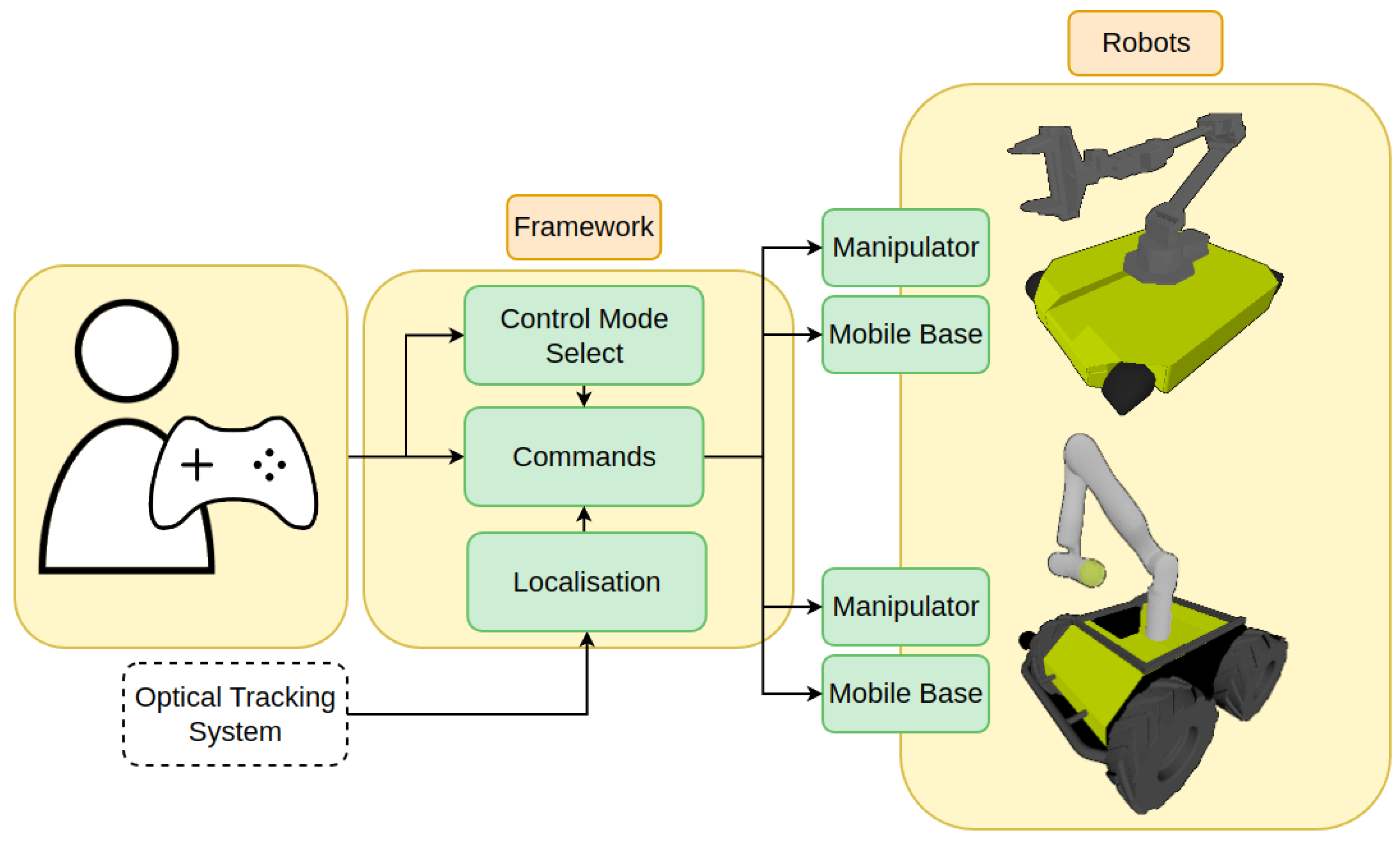
In this paper, we propose a teleoperation framework utilising external localisation to couple two legged manipulator robots to perform feasible bimanual manipulation within the frames of the two robots. Due to this, the framework is able to control the robots during the manipulation phase. An overview of the framework is illustrated in
Figure 1.
Due to the structure of the framework and the distinction between locomotion and manipulation modes, it is possible to control any combination of manipulators, mounted or fixed, and mobile bases. In addition, due to the use of high-level commands, the control framework should be compatible with any robotic mobile base and manipulator, such as wheeled or legged robots, both unidirectional and omnidirectional.
Our approach uses two separate mobile bases with a mounted manipulator in tandem with a localisation system to allow successful bimanual manipulation to be performed through the use of a teleoperation control framework that allows for easy mode switching and the control of every robot system and co-operative movement. The framework was verified in simulations through the use of joystick gamepad control.
2. Control Mode Deduction
The difficulty in bimanual manipulation comes from the fact that both robotic arms must conduct motion in a highly synchronised manner to achieve smooth manipulation.
Therefore, to perform bimanual manipulation in a feasible manner, the first consideration should be how to prevent unwanted movements of the robotic arm end-effectors in the scenario where both arms are manipulating a single object.
When both robotic arms are not on the same rigid structure, motion planning becomes more difficult as the distances between the co-operating robotic arms is not known. Therefore in our approach, we chose to use a localisation system to counteract this.
Currently, to localise the two robotic systems, we use optical markers mounted on the bases of both robotic arms and the Optitrack system [
18]. The Optitrack system allows us to obtain the positions and orientations of each marked robotic system with respect to a calibrated world frame origin. In the simulation, localisation is performed by simply retrieving the positions and orientations of each robot and calculating the difference.
Using the locations of each robot with respect to the world frame origin, we can calculate the relative location of one robot from the other.
After obtaining the relative locations, we can couple the transforms of both robots into a single system. This allows for various parameters to be obtained, such as the relative position and orientation of one end-effector to the other.
The localisation system is used when obtaining the distance between the manipulator bases and the orientation difference for use in bimanual manipulation calculations. The distance reference is also used to maintain the distance between the mobile bases in certain control modes of the framework where both mobile bases are moving in unison.
Control Mode Deduction
Success in teleoperation scenarios is largely impacted by the mobility and manipulation capability of the teleoperated robotic system [
19,
20]. Therefore, between two separate mobile manipulator systems, all control modes and control combinations that can be formed between the different sub-systems must be considered.
As the number of mobile base sub-systems that are required to be controlled increases, the possibility of combining multiple systems in a control group increases. The difficulty in selecting a specific combination of sub-systems to control also becomes a concern.
To ensure that the framework is able to control every combination, we form an equation that takes the number of mobile manipulators and number of fixed manipulators in a system and outputs the total number of control modes that can be formed with a set combination. However, there must be at least two manipulators in the system, as many of the modes assume that cooperative manipulation is possible.
We therefore deduce the total number of modes in multiple legged manipulators and a manipulator system, with the assumption that the sub-systems are able to cooperate with each other, using the following Equation:
where
n represents the total number of manipulators that are present in the entire system,
m represents the number of mobile bases in the system.
k is an index variable in both cases. The first binomial coefficient is used to calculate the total number of combinations of cooperative manipulations between the total number of manipulators.
k in this instance is initialised at 2 as this is the minimum number of manipulators required for cooperation to exist. The second binomial is used to calculate the total number of combinations of mobile base movements.
k is initialised at 1, as a single mobile base is required for movement to be possible. The function is then multiplied by 2 to account for the inclusion of a held object when moving. An assumption that is made is that all end-effectors in cooperative manipulation are coupled in space, meaning that modes that control only one of the end-effectors are excluded, resulting in fewer total modes than total possible combinations throughout the systems.
For example, in the case of two fixed arms, the parameters would be , . As such, the output of the equation would be .
In the case of a fixed arm and a mobile manipulator, the parameters would be , . As such, the output of the equation would be .
In the case of two mobile manipulators, the parameters would be , . As such, the output of the equation would be . Although there are 11 modes, these are sorted into a fewer number of mode groups, where the control of the mode is the same, but the target base/end-effector can be quickly cycled through.
The total number of mode groups for a specific system is double the number of manipulators present.
A description of each of the 11 modes in 6 mode groups for this case are displayed in the table below.
3. Control Framework
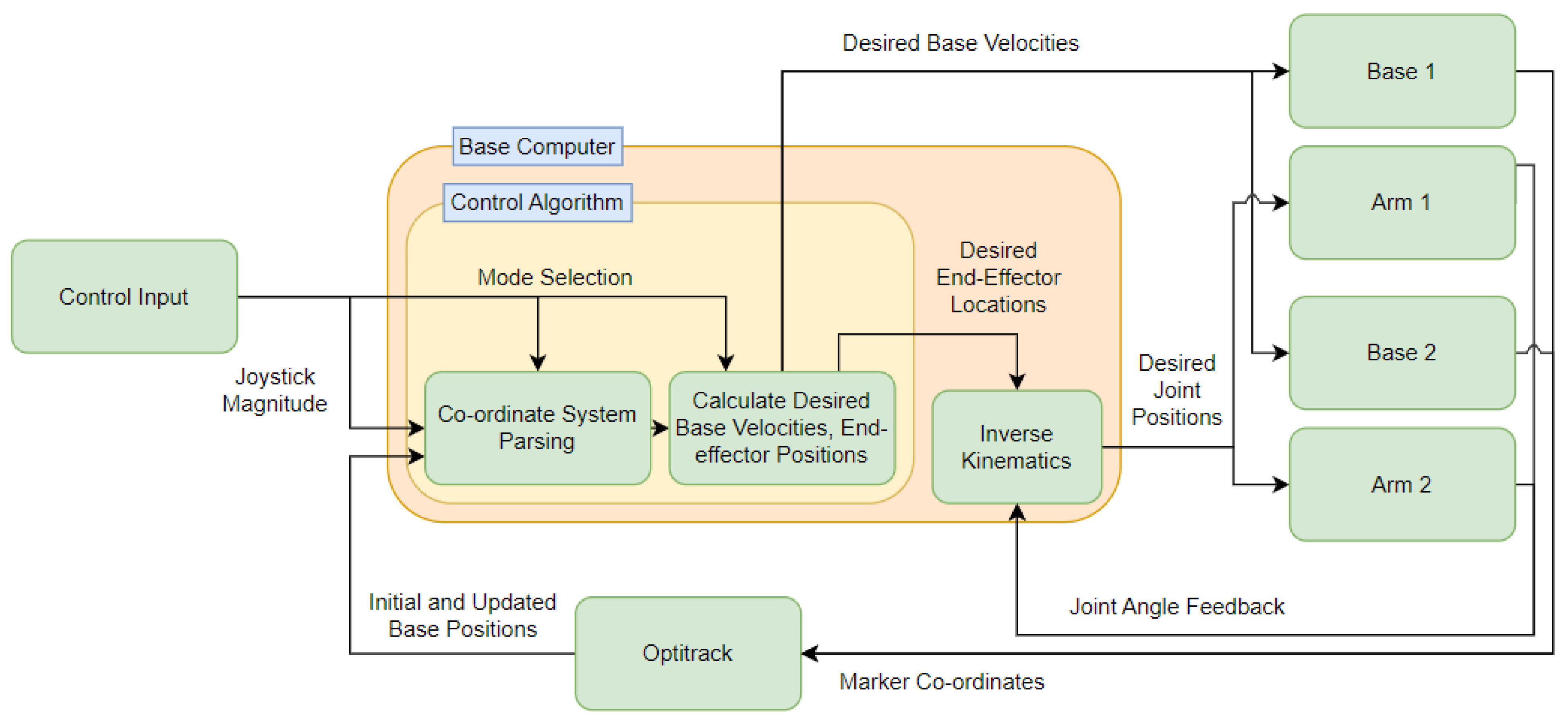
Figure 2 contains a flowchart containing all aspects of the control framework and the respective data flow.
The goal of the framework was to enable a somewhat simple control of multiple mobile manipulator systems that could also be used for complex manipulation applications. User commands are received via a joystick controller that directly communicates with the framework. The joystick input command will serve a different purpose based on which mode is currently selected, which can also be cycled through using a button on the joystick. These commands can either control the base velocity or the end-effector positions, either through individual control, where the Cartesian position is directly controlled, or through bimanual manipulation, where multiple end-effectors are coupled together spherically and controlled by adjusting the Cartesian positions and Euler angles.
Upon starting the framework, the Optitrack system initialises the base positions of both mobile bases, and the initial end-effector locations are sent to each arm, allowing for the locations of each base and end-effector to be known to the framework. Mode selection is then used to determine which co-ordinate axes to control before calculating the desired velocities and positions of the mobile manipulators.
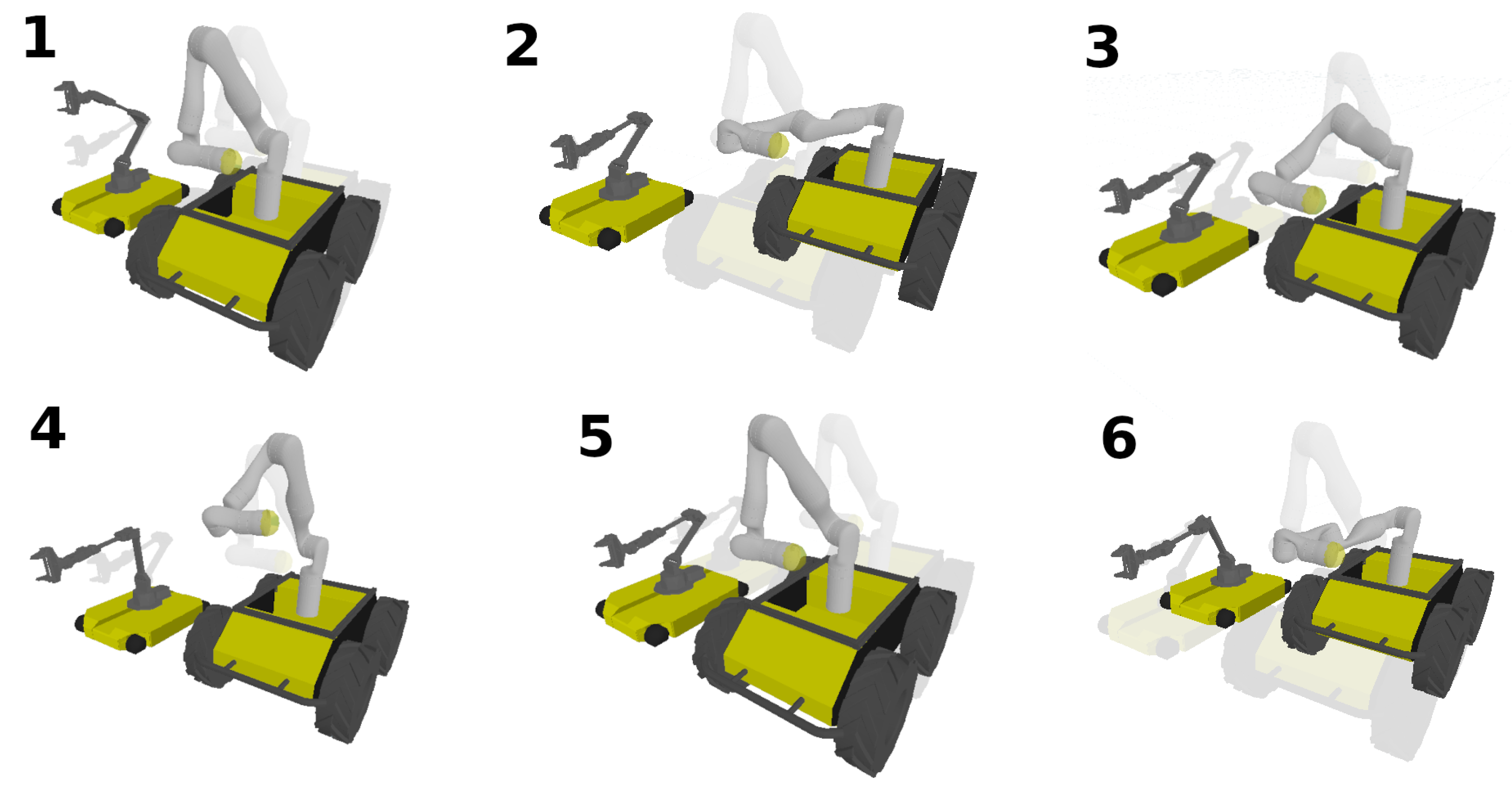
The mode selection is formulated as a simple state machine, where a single trigger is used to pass from state to state. There are a total of six states representing the mode groups, with additional sub-states to specify the platform to control, i.e., each specific control mode. These modes are illustrated in
Figure 3. An illustration of the axis used for control are illustrated in
Figure 4.
The Individual System Control of each base and robotic arm for both bases entails base control with the object fixed in the world and base control whilst coupled with the object, followed by bimanual telemanipulation, simultaneous base control whilst coupled with the object and simultaneous base control with the object fixed in the world.
Apart from the individual control, all other modes control the two robots assuming that both robots are manipulating a common rigid object. An expanded description of each mode can be found in
Table 1, along with potential applications in
Table 2.
3.1. Individual System Control
Mode 1, the individual control of a sub-system, simply controls either a single quadruped base or a manipulator by generating a base velocity or an end-effector trajectory, respectively. The system chosen is cycled through using a button on the joystick. This is the only mode that is used outside of cooperative manipulation and hence does not require the use of the optical tracking system to function. Much like the traditional control of a quadruped base or a robotic arm, this mode allows the user to control each system individually. For individual control, we use linear control via a joystick to adjust the velocity and target position of the base and robotic arms, respectively.
x refers to a Cartesian position vector of the respective system noted in the subscript.
In each mode, the control of a specific base uses the same logic as presented in Equation (
3). This is not the same for the robotic arm end-effector control in other modes, as object-orientated control is adopted instead.
3.2. Bimanual Manipulation
Mode 4, bimanual manipulation, is activated when both end-effectors are holding onto the same object. The optical tracking system first finds the difference in distance and orientation between both robotic arm bases in the world frame. As the object is mathematically modelled as a sphere, where both end-effectors are on the circumference, once the world frame locations of both arms are determined, the initial end-effector positions on the sphere are determined. All parameters are defined within the world frame.
Equations (4)–(8) focus on deducing the original Euler angles of a held object when the bimanual manipulation mode is enabled. Equations (9)–(14) then focus on obtaining the new Cartesian positions and Euler angle orientations of the end-effectors after a command is sent.
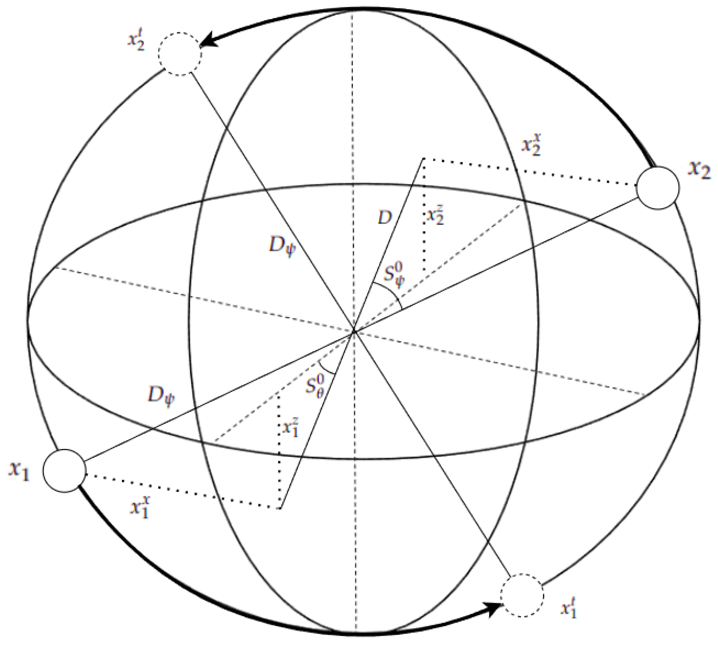
At the start, in the case of the simulation, the end-effector’s world pose is retrieved, and in the experiment, the end-effector’s world pose is calculated from the optical localisation of the robotic bases. A sphere is then formed between the two end-effectors, specifically the tool centre points, with a diameter being formed between them.
refers to the Cartesian position of the centre of the sphere, and the superscript 0 refers to the original value at t = 0.
refers to the Cartesian position of the first end-effector, all within the world frame.
refers to the magnitude of the diameter of the sphere that is formed in between the end-effectors.
refers to the
x component of the Cartesian position. These parameters are illustrated in
Figure 5.
Next, the current yaw and roll of the formed sphere are calculated. The pitch is ignored, as pitch control is about the diameter of the sphere between the two end-effectors.
refers to the original yaw orientation of the sphere at time = 0.
D is the new diameter that is calculated once the yaw is removed from the sphere, allowing for the roll to be calculated.
is then the original roll orientation of the sphere at time = 0.
In the bimanual manipulation mode, the teleoperator directly controls the position and orientation of the object.
where
represents the desired Euler orientation of the sphere at time
t.
Following this, the new locations for each end-effector are calculated:
where
refers to the new Cartesian position of the first end-effector at time
t. The Cartesian positions are represented by
x,
y, and
z.
With this, the final orientations of the end-effectors are then deduced.
where
refers to the end-effector roll and pitch orientation in the world frame.
R refers to a ratio value calculated to split the desired pitch between the pitch and roll axes for when the end-effectors have a different yaw orientation in the world frame.
3.3. Base Control with Object Fixed
Mode 2 is similar to the individual control of a quadruped base; however, during bimanual manipulation, the manipulator mounted on the respective controlled base will adjust its end-effector location to keep the held object stationary in the world frame. The mobile manipulator that is not being controlled will also remain stationary. Due to the object being stationary, however, the base’s movement is limited by the robotic arm’s workspace. As everything is modelled around the master base as the origin, the requirements to enable each behaviour is different for each robot.
where
is the sphere position and yaw orientation in the world frame.
is the change in base position and orientation over time
t of the master robot (controlled) in the world frame.
3.4. Base Control Coupled with Object
Mode 3 also controls a base’s movement, with the difference being that the object that the controlled base is holding will remain fixed in space relative to the controlled base. Due to this, moving the base and object will cause the manipulator on the other base to react and move its end-effector location to maintain contact with the object. Due to this, the movement is then limited by the workspace of the other manipulator. This mode is represented in the simulation as a transform of both the object and manipulator about the other manipulator.
where
is the sphere position and yaw orientation in the world frame.
is the change in base position and orientation over time
t of the master robot (controlled) in the world frame.
3.5. Control of Both Bases Coupled with Object
Mode 5 is used to move and rotate every system, including the held object in the world frame. The position and orientation of the object are also locked within the robot frame. In the simulation environment, this is formulated as a transformation that affects every element. This mode relies heavily on the update frequency of the framework.
where
is the difference in the Cartesian position and Euler yaw between the two robot bases.
M and
S refer to the robot base that is controlled by the teleoperator and the robot base that is being automatically controlled by the control framework, respectively.
is the desired Cartesian position and yaw orientation of the robot base controlled by the framework.
is a rotation matrix created from the distance between the two robot bases and the change in yaw of the main teleoperated robot.
3.6. Control of Both Bases with Object Fixed
Mode 6 fixes the position and orientation of the object in the world frame and allows for both bases to move in conjunction with each other. The equations are the same as above, with the addition of one equation to offset the object by the change in base position, causing it to be fixed in the world frame.
4. Simulation Results
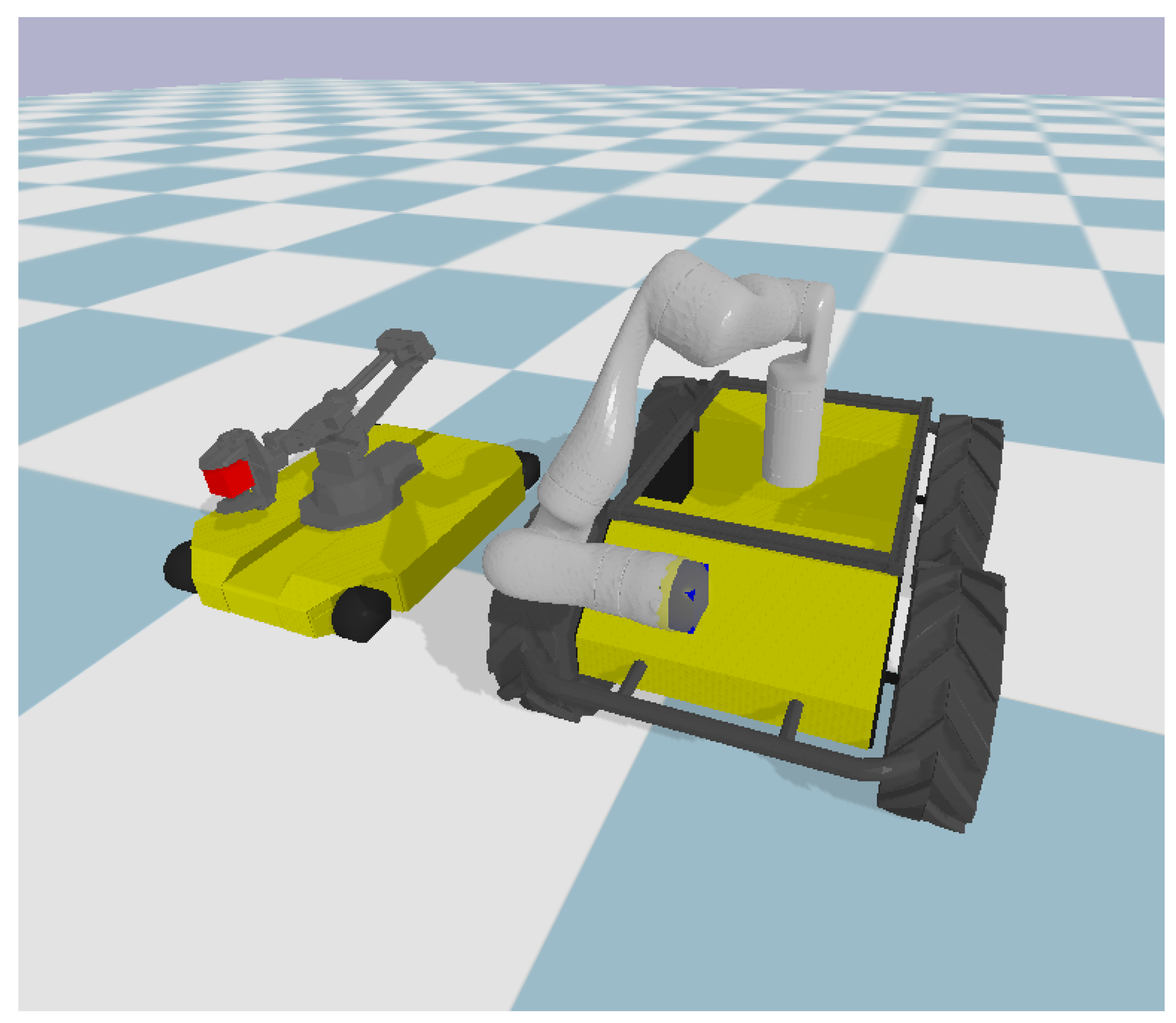
A Pybullet simulation with two mobile manipulators was used. The Clearpath Husky and the Clearpath Dingo with a mounted Jaco robotic arm and a ViperX 300s robotic arm on the top side of each base were used, respectively. These can be seen in the simulation in
Figure 6. In a simulation, all modes of control can be tested.
Each mode of the control framework was first validated in the Pybullet simulation. Throughout the simulation testing, the position and rotation feedback in the world frame for each robot and end-effector was used for localisation for the control framework. This was later replaced with the optical localisation method in real-life experiments.
To show the accuracy and stability of the trajectories generated in the bimanual manipulation mode,
Figure 7,
Figure 8 and
Figure 9 illustrate the movements generated by the framework for the simulated robots.
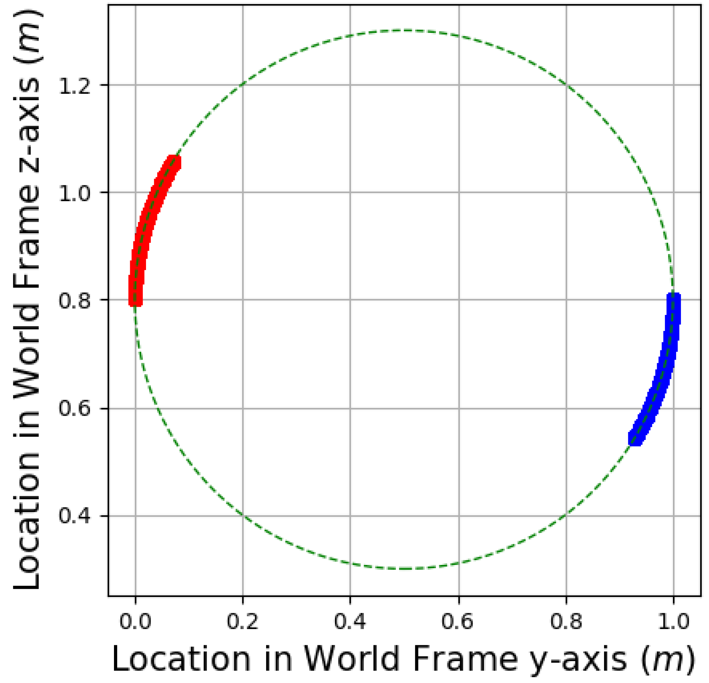
Figure 7 illustrates the movement of both robotic arm end-effectors when a roll trajectory is generated and sent from the framework. The red and blue curves represent the position of each end-effector in the world frame over the course of the roll command. The dashed-line circle represents a circle with the same diameter as the distance between the two end-effectors at the start of the roll command.
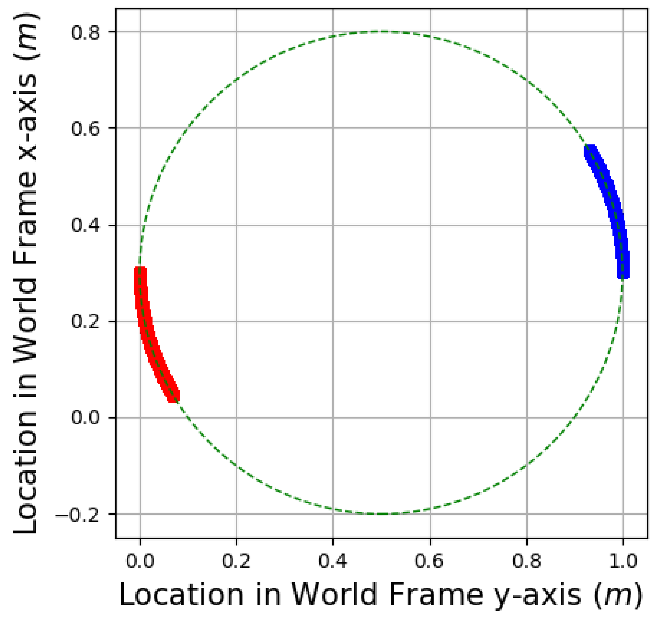
Figure 8 is similar to
Figure 7, except it shows movements on the yaw axis instead. In both
Figure 7 and
Figure 8, the end-effectors are normal to the sphere, and both are on a straight line that intersects the centre of the circular trajectory.
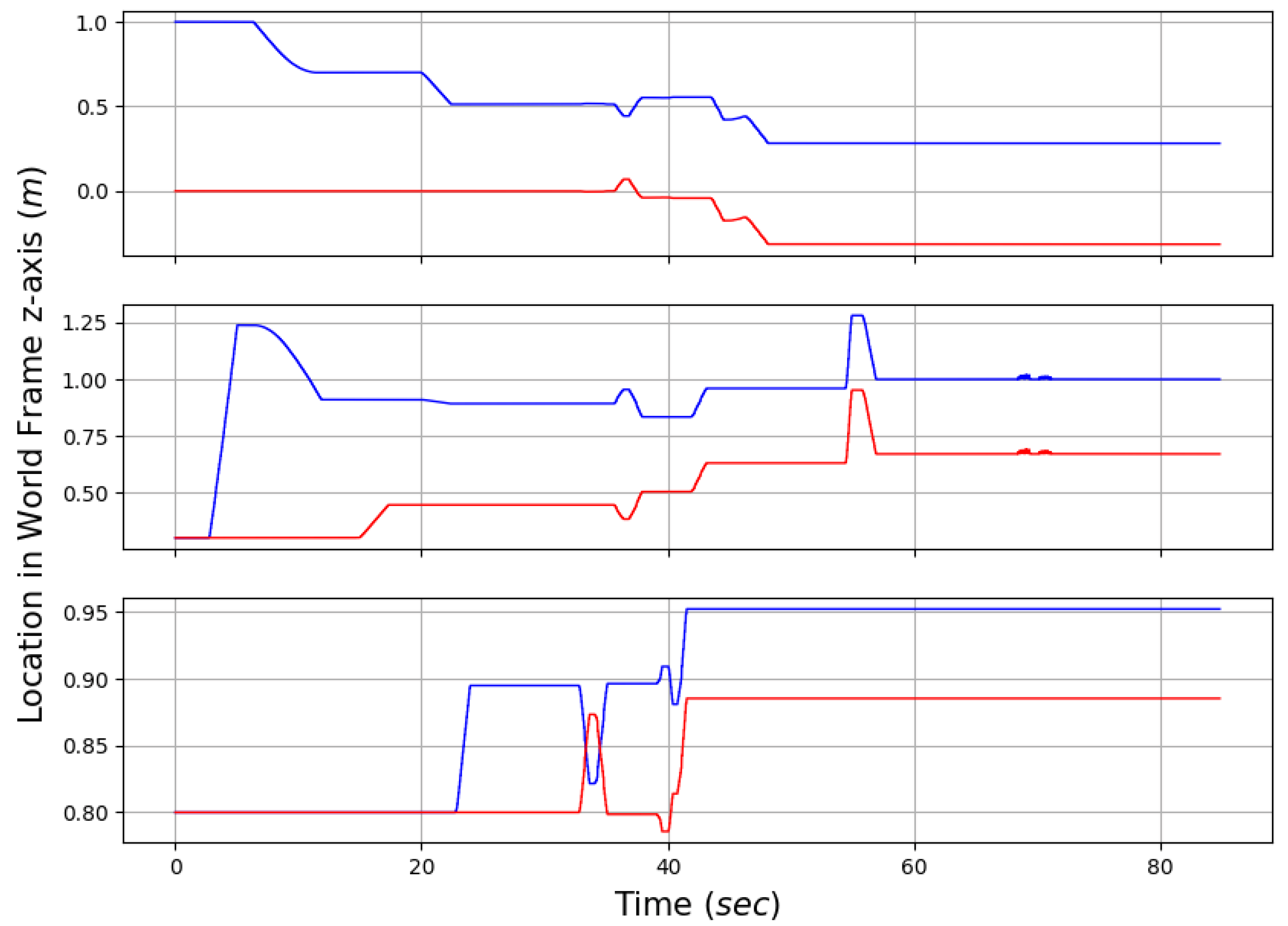
In addition to bimanual manipulation is a separate experiment, in which each other mode is shown to be working as intended in
Figure 9. From 0 to 4 s, the second base moves forwards, keeping its end-effector stationary in the robot frame but exhibiting stable forward movement in the world frame. From 6 s to 12 s, the second base rotates to the left. From 15 s to 17, the arm of the first base moves forwards. From 20 to 22 s, the second arm moves forwards. From 22 to 23, the second arm moves vertically up. At 32 s, bimanual manipulation is enabled, and both arms conduct a roll trajectory before returning back to their initial pre-roll positions. This is followed by a short yaw movement at 37 s and then another roll at 39 s. This is then followed by coupled vertical up, forward, and left translation movements at 41, 43, and 44 s, respectively. At 55 s, both bases move forward and then backwards in a coupled movement. This is followed by a forward movement decoupled from the end-effector of the first base at 62 s, followed by the second base at 68 s.
5. Results
To verify the functionality of the bimanual manipulation system, an experiment was conducted with two quadruped manipulators using an Optitrack optical tracking system.
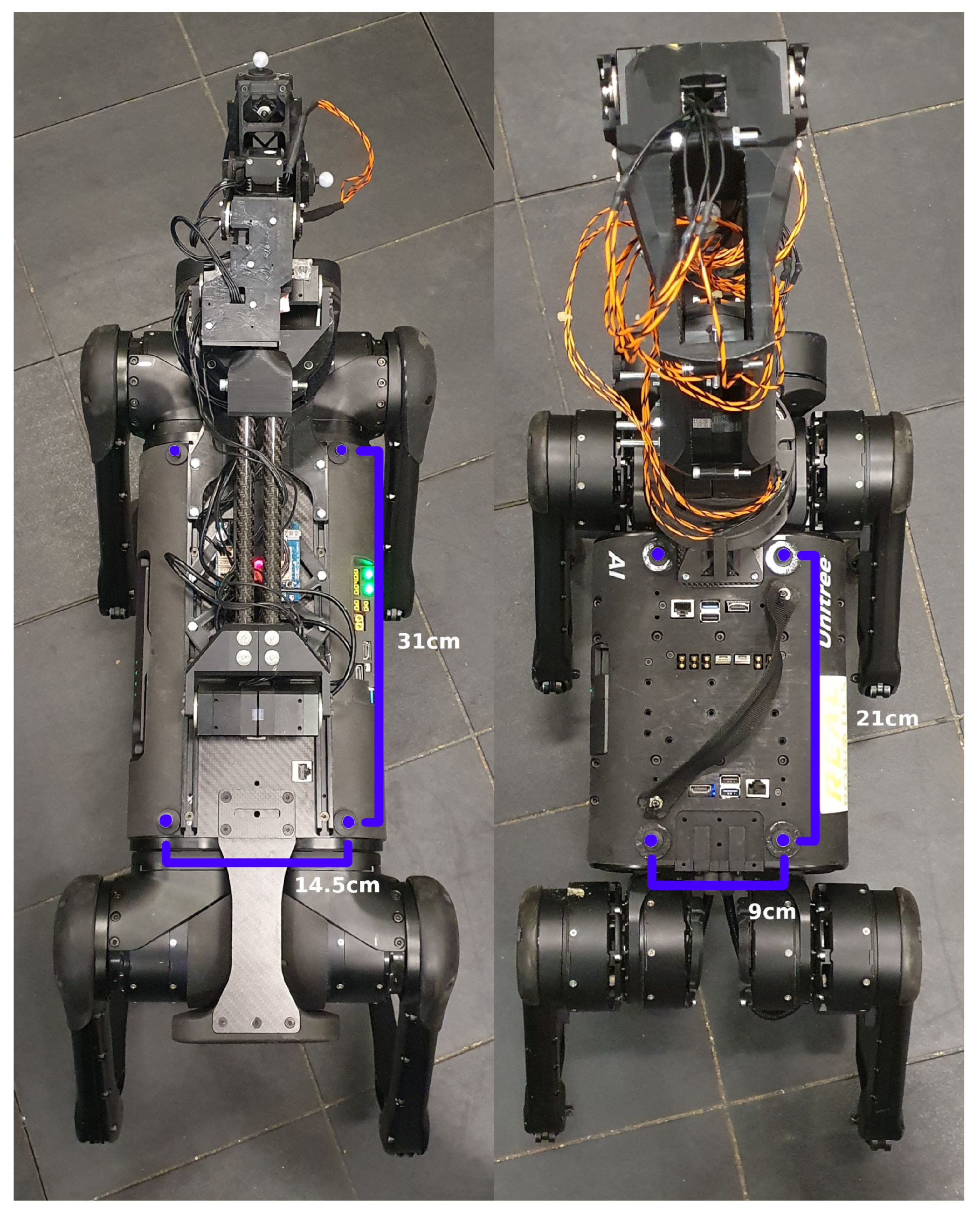
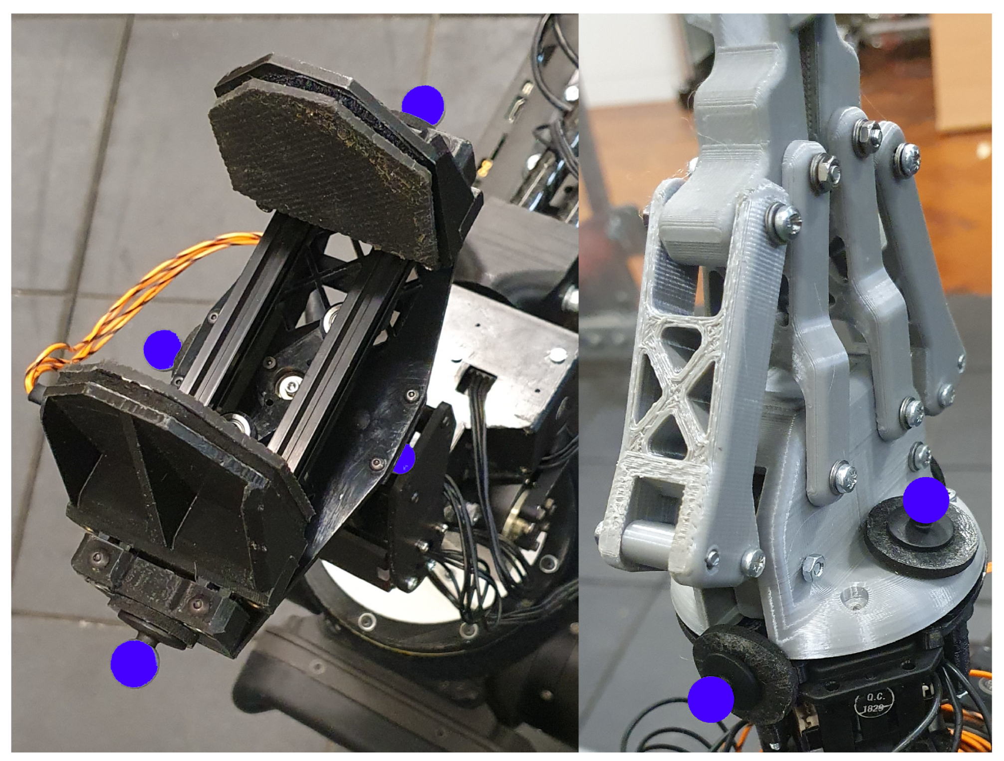
The Optitrack system tracks the position of a body formed around each robot through the use of optical markers. The purpose of the Optitrack system in this experiment was to replicate, as closely as possible, the perfect conditions for localisation, like those in the simulated experiments; this was realized through the use of multiple cameras arranged around the experimental area to minimise the loss of tracking of each system. In the future, this method of localisation will be replaced with a method more practical for field robotics and thus will have imperfect conditions and potentially experience the loss of tracking at various points. Two sets of optical markers were used in the experiment. The first set was located on each corner of the quadruped base, forming a body around the base, with the centre point being the centre of the base itself. These centre co-ordinates were used in the control framework to co-ordinate the mobile bases during the respective control modes and also to deduce the locations of the end-effectors for use in the bimanual control modes. The second set of optical markers were placed around the end-effector of each robotic arm; however, these were purely for data collection and served no purpose within the control framework. These optical tracker locations can be seen in
Figure 10 and
Figure 11, where they are highlighted in blue. Substantial consideration was made to ensure the optical markers placed on the robot would form a centre point that correctly represented that of the actual robot. To assist in placing the markers, geometric features on the robot’s base were used as attachment points. The dimensions of the optical markers on each base can been in
Figure 10. The dimensions of the polygon formed by the optical markers in
Figure 11 are 8.5 cm by 17.5 cm and 6.5 cm by 9.5 cm, respectively. The experimental area is approximately 3 m by 4.5 m and contains 11 Optitrack cameras, each mounted on the perimeter of the area at an elevation of approximately 2.5 m and facing inwards towards the experimental area.
The Optitrack system output pose data for all marked bases and arms at 120 Hz.
The mobile platforms used are the A1 and Aliengo quadruped robots, and mounted on the topside of the platforms are a bespoke 6-DoF robotic arm and the ViperX 300s 6-DoF robotic arm, respectively. The experiment revolved around verifying the functionality of each separate mode contained within the framework.
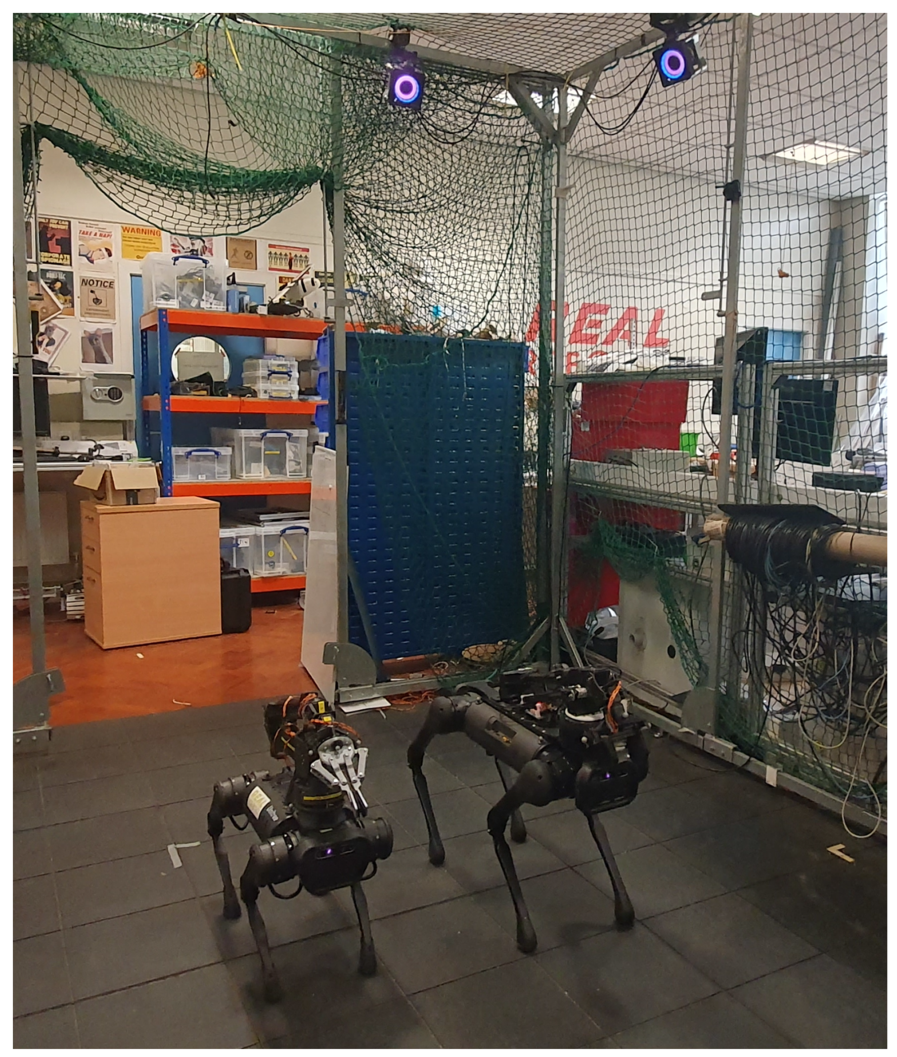
The real-life experiment setup is illustrated in
Figure 12, where two quadruped manipulators can be seen, as well as several optical tracking cameras. Beyond the figure, there are many more optical tracking cameras forming 360-degree coverage of the markers inside of the experimental zone, minimising the loss of tracking.
Each of the following figures was constructed using data that were collected using the optical tracking system Optitrack as the ground truth for the locations of the end-effectors and robotic bases.
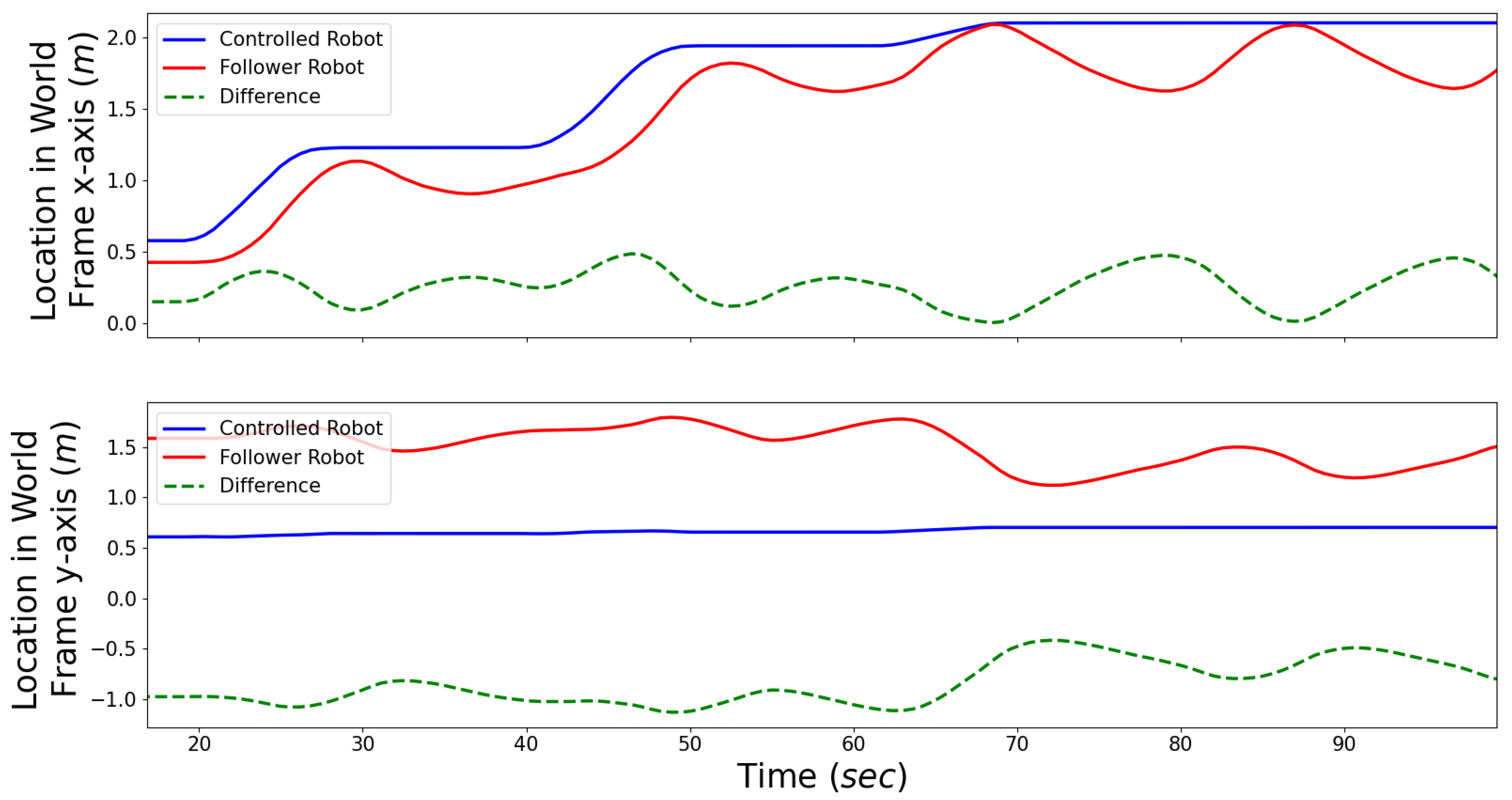
Figure 13 plots the two-dimensional location of each robotic base (excluding the vertical axis, as this does not change), along with the difference between the two bases. This graph illustrates the robot-to-robot following capabilities required for modes 5 and 6 to be functional. It can be observed that, even though there is some positional fluctuation, the follower robot keeps to the trend of maintaining its location relative to the controlled robot. Due to the use of high-level controls to maintain the relative distance, as well as potential delays in velocity due to the nature of legged robots being reliant on stepping cycles, the increasing fluctuations in the line labelled “difference” in each graph, having a magnitude of 0.3–0.5 m on both axes, with prolonged movement prove that it can be further improved to improve the stability and reliability of the following capability, as this is required for the translation of objects during bimanual manipulation. This will be improved in the future with the implementation of an improved feedback loop in the controller.
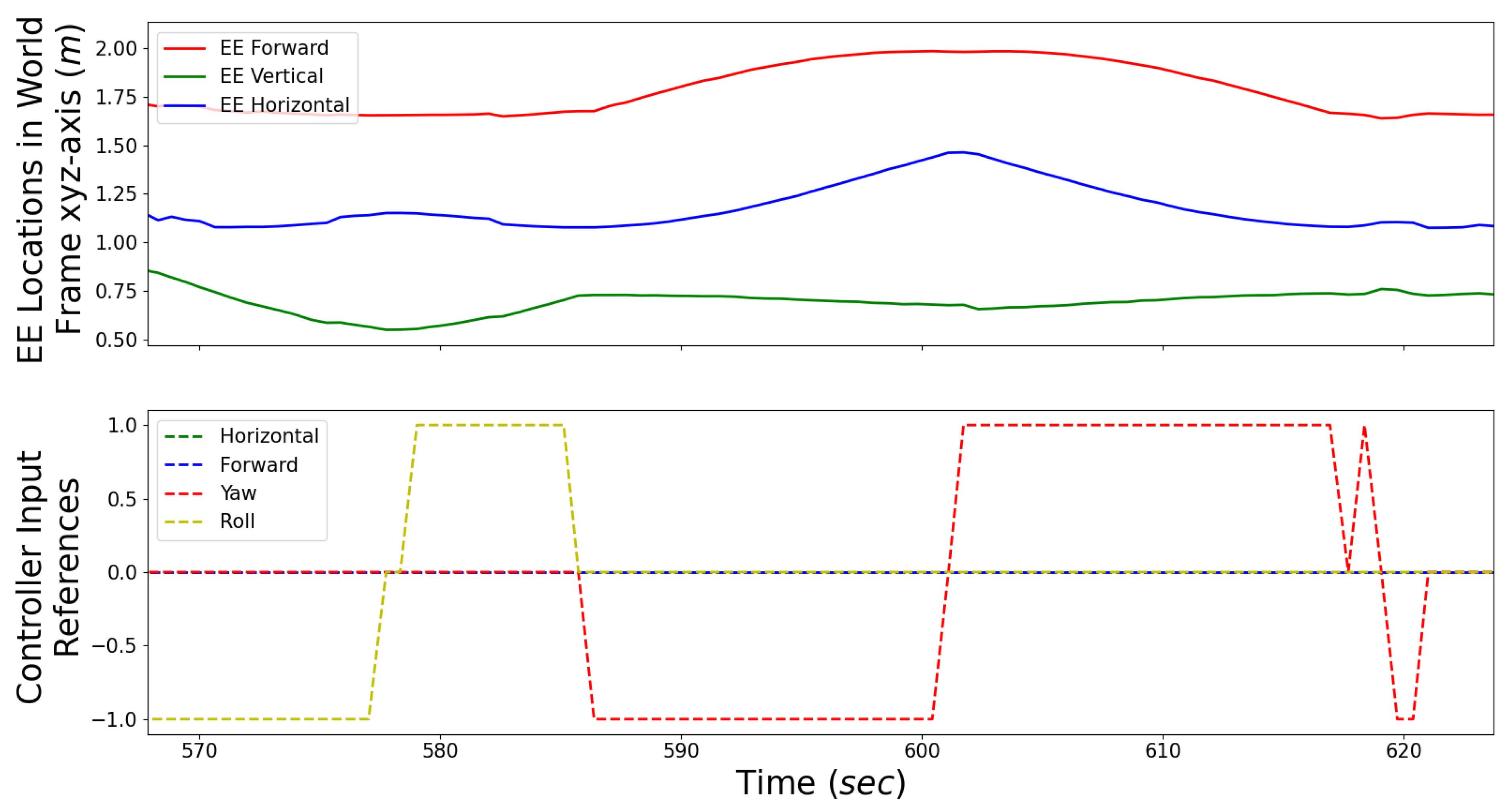
Figure 14 and
Figure 15 both illustrate the change in the Cartesian position of an end-effector when given a control input reference. However, in the former, the end-effectors are restored to their initial positions after each reference. Therefore, it can be seen in the latter that some rotation references cause a change in position in several Cartesian axes. In this experiment, the location and orientation of the object were not tracked. However, the trajectory of the end-effector can be seen reacting to the corresponding inputs from the controller. As can be seen from each graph, the controller input can feasibly control the respective location of each end-effector. Comparing the two figures, it can be seen that each command affects the movement of the end-effector on two axes due to the spherical trajectory. In
Figure 15, the magnitude of displacements on each axis are increased due to the end-effectors not being level. Unlike the locomotion experiment, there is minimal unintentional disturbance in the end-effectors’ trajectories, indicating that additional feedback systems are not necessary.
Because each experiment included the use of two mobile platforms, it can be safe to say that the framework would also work for two fixed robotic arms or a combination of one mobile manipulator and one fixed robotic arm.
6. Conclusions
In this paper, we propose a novel teleoperation framework that would allow a teleoperator to control multiple robotic systems at once and perform both unimanual and bimanual manipulation trajectories in a feasible manner, as well as co-operative locomotion. The framework was validated in simulations and with preliminary real-life experiments with two mobile manipulator systems.
As seen in the experiments, manipulation using this framework is currently stable; however, the fluctuations in relative positions during robot-to-robot following indicate that further improvements in stabilisation through the use of feedback loops in the controller, such as PID, are needed. Further work will include the development of a stabilised locomotion system as well as additional experimentation, where bimanual manipulation tasks will be performed simultaneously with the improved locomotion system.
Currently, the framework is unilateral; however, in the future, there is much potential for the implementation of haptic feedback into this framework, as the additional information gained from this feedback could reduce the time between each state in the framework and assist in enabling delicate manipulation scenarios, as well as increasing immersion for the teleoperator, reducing learning time and potential mental load.
As this solution requires a fixed localisation system, in the future, the Optitrack system will be replaced with a localisation system capable of obtaining the locations of the two robots with respect to each other without the area limitation that using an optical/visual system such as Optitrack entails, thus being more useful for applications where teleoperation is required.


