Article

Design and Evaluation of a Novel Passive Shoulder Exoskeleton Based on a Variable Stiffness Mechanism Torque Generator for Industrial Applications †

1
Department of Electronic Systems, Aalborg University, 9220 Aalborg, Denmark
2
Department of Material and Production, Aalborg University, 9220 Aalborg, Denmark
*
Author to whom correspondence should be addressed.
This paper is an extended version of a paper published by Zhu, Y.; Balser, F.; Shen, M.; Bai, S. Design and Evaluation of a Novel Passive Shoulder Exoskeleton Based on VSM Torque Generator. In Advances in Mechanism and Machine Science—Proceedings of the 16th IFToMM World Congress 2023—Volume 2, Tokyo, Japan, 5–10 November 2023; Okada, M., Ed.; Springer Nature: Berlin, Germany, 2023; pp. 810–819.
Robotics 2024, 13(8), 120; https://doi.org/10.3390/robotics13080120
Submission received: 28 June 2024 / Revised: 27 July 2024 / Accepted: 6 August 2024 / Published: 8 August 2024
(This article belongs to the Section Intelligent Robots and Mechatronics)

Abstract

:
Work-related musculoskeletal disorders (WMSDs) are a common occupational health problem in industries, and they can lead to decreased productivity and a reduced quality of life for workers. Exoskeletons, as an emerging technology, have the potential to solve this challenge by assisting arm movements and reducing muscle effort during load lifting tasks. In this paper, a passive exoskeleton based on a variable stiffness mechanism (VSM) torque generator is proposed and evaluated. This exoskeleton can provide adjustable torque curves and accommodate three degrees of freedom (DOFs) while remaining compact and lightweight. The workspace analysis shows that the workspace of this exoskeleton is sufficient for most industrial manual handling tasks. The experimental results demonstrate that the exoskeleton effectively reduces muscle effort during overhead reaching and load-lifting tasks, highlighting its effectiveness for repetitive tasks in industrial settings.

1. Introduction

Exoskeletons are wearable machines worn on the human body for motion assistance and power augmentation in the form of either upper-body, lower-body, or full-body exoskeletons [1,2]. They have been found in many applications, ranging from medical rehabilitation to industrial settings [3], one of which is to prevent WMSDs for physical workers in various industries. WMSDs include disorders in the muscle, skeleton, and related tissues. This is a common occupational health problem in various industries [4]. Approximately half of WMSDs affect the shoulder and lower back muscles of industrial workers who perform repetitive tasks at overhead heights [5]. WMSDs are particularly prevalent in the manufacturing industry [6,7,8], where some manual handling tasks are difficult to robotize, making human workers essential and central [9]. WMSDs consequently affect worker productivity, incur healthcare costs, and impact quality of life due to limited mobility and increased rehabilitation costs [10,11]. In Germany, for example, muscle disorders caused a total loss for 47.6 billion in 2016, which included both the social expenses and loss of labor productivity [12]. Thus, industries are showing a growing interest in exoskeletons to aid workers in manual handling tasks and mitigate the risk of WMSDs, benefiting both employers and employees.
Exoskeletons, by assisting human limb movements, can effectively reduce muscle effort. Based on the energy source, exoskeletons can be classified into active exoskeletons and passive exoskeletons. Active exoskeletons include actuation systems that generate torque actively, such as electrical [13,14,15], pneumatic [16,17,18], and hydraulic actuations [19,20,21,22]. However, active exoskeletons are, in general, complicated, and they require on-board batteries and control units, making the entire system bulky and heavy [23]. Furthermore, the control system must be properly designed to provide the needed torque and ensure stability [24,25]. Rather than adopting active actuators, passive exoskeletons can provide assistive torque through the stored potential energy in elastic elements, which are in the form of either mechanical springs [26,27,28,29] or gas springs [30,31,32]. Notably, researchers also utilize magnetic springs on the passive exoskeletons to compensate for the gravity acting on the upper limbs [33,34]. Compared to active exoskeletons, passive exoskeletons are typically lighter and less complex, since there is no actuator or external power source needed [35]. In industrial applications, passive shoulder exoskeletons enable workers to slightly enhance their load-lifting capabilities while significantly reducing muscle fatigue during repetitive manual handling tasks [36]. Examples of commercial passive shoulder exoskeletons include Skelex 360 [37], Vex [38], and Paexo [39], adopting either leaf springs or linear springs, and EVO [40] which adopts a gas spring can provide 2.2–6.8 kg of lifting force to each arm. For these exoskeletons, overcompensation, which describes the condition where the exoskeleton provides more assistance than required, can reduce the muscle activities involved in shoulder flexion. However, in the case of extension, muscle activities are increased, which means that the exoskeleton impedes the natural movement of the subjects [41]. Therefore, it is desirable to make the torque profile adjustable for different individuals to avoid overcompensation. In addition, exoskeletons remain bulky and heavy, which impedes their widespread applications in the industry. Therefore, more compact and lightweight passive exoskeletons are needed for high-performance assistance and also for their widespread application.
In this paper, a passive shoulder exoskeleton that incorporates the variable stiffness mechanism (VSM) principle is presented. By adopting the VSM, a novel torque generator that is both compact and capable of providing adjustable assistance was developed. This work is based on our previous research [42] in which we presented the foundational principles of the shoulder mechanism design. In this study, a portable shoulder exoskeleton that can accommodate the three primary motions of human shoulder joints was developed. To assess the effectiveness and practicality of this exoskeleton in real-world scenarios, a series of load lifting experiments were conducted. These experiments were designed to evaluate the exoskeleton’s performance in reducing muscle strain and improving overall efficiency by mimicking manual handling tasks.
This paper is organized as follows: In Section 2, the concept of the torque generator with the variable stiffness mechanism (VSM) principle is introduced. Section 3 describes the mechanical design of the passive shoulder exoskeleton. Section 4 presents a comprehensive workspace analysis of the exoskeleton, evaluating its range of motion and ability to accommodate the three primary motions of human shoulder joints. Section 5 describes the preliminary load lifting experiments carried out to assess the exoskeleton’s performance. This work is discussed and concluded in Section 6.

2. Basic Design Concept of the VSM Torque Generator

The VSM was first proposed by Li and Bai in [43], then applied to the design of exoskeletons [44]. Here, we provide a brief overview of the VSM principle for completeness.
The design of the VSM is based on a four-bar linkage. Figure 1a illustrates a specific case where bar 4 becomes zero-length and bar 2 is replaced with an elastic element. Building upon this zero-length base link four-bar linkage concept, a new mechanism is implemented using a pulley cable system connected to a linear spring, as shown in Figure 1b. Here, bar 1 and bar 3 can be seen as the input and output levers, respectively.
Figure 1c demonstrates a torque generator concept implemented with input and output plates coupled with pulleys and cables to achieve varying stiffnesses. The configuration shown in Figure 1b is replicated to expand the stiffness range.
As shown in Figure 1a, the force applied to link 1 equals the force generated by the spring. Therefore, the torque applied to link 1 can be expressed as follows:
τ = J · F
where F is the tension force in the spring and J is the Jacobian, which can be further written as follows:
F = k · Δ l 2 + F 0
J = l 1 l 3 sin θ l 1 2 + l 3 2 2 l 1 l 3 cos θ
where l 1 and l 3 are the lengths of bar 1 and bar 3 shown in Figure 1a, respectively. θ is the deflection angle between bar 1 and bar 3. k, Δ l 2 , and F 0 are the stiffness, elongation, and pretension force of the spring, respectively.
Figure 1c shows the torque generator utilizing VSM, constructed with cables and multiple pulleys. In this design, the output torque is expressed as follows:
T V S M = c 2 · N 2 · J · k · Δ l 2 + c · N · J · F 0
Here, the geometrical factor c denotes the influence of mechanical geometry on cable elongation, while N represents the number of pulleys on the output plate.
Figure 2 illustrates the torque distribution of the VSM concerning the deflection angle and pretension, computed using Equation (4), with the parameters set to c = 2 , N = 1 , k = 5.4 N/mm, l 1 = 22.4 mm, and l 2 = 32.5 mm.

3. Design Implementation of the Exoskeleton

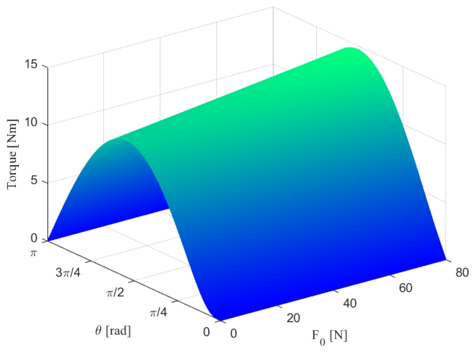
3.1. Parameter Optimization of the VSM

As shown in Figure 2, the torque generated by the VSM depends on various parameters, including geometric parameters, material properties, and the layout of the pulley–cable–spring system.
Considering the range of rotation of the shoulder joint, only one pulley is utilized to avoid interference between the moving pulley and the central axis and to maximize the rotation of the joint. Moreover, the required torque should closely match or equal the torque needed to lift the arm. This can be achieved through design optimization.
Utilizing the lengths and masses of the arm segments, a 7-degrees-of-freedom (DOF) model of the human arm was first developed, similar to the approach outlined in [27]. With this model, a resulting torque curve for motion in the sagittal plane can be calculated. An objective function was then defined, aiming to minimize the difference between the required torque of the human arm and the torque provided by the exoskeleton.
The optimal design was implemented using an interior point algorithm [45]. The objective function in the optimization is given as follows:
f ( x ) = β l β u α l α u [ w · ( T S ( β , α ) + T V S M ( β , x ) ) ] 2 d α d β 1 / 2
where x = [ l 1 , l 3 , k , F 0 ] T ,which contains the parameters of the VSM that need to be optimized. Here, T S is the shoulder torque, which can be found in [42]; T V S M is the VSM torque, calculated using Equation (4); and w is a weight function used to amplify certain positions over others. The boundaries ( α l , α u ) and ( β l , β u ) are determined by the range of joint rotations, which are α l = β l = 0 ° , α u = 150 ° and β u = 180 ° . α and β are the elbow and shoulder angles, respectively, as illustrated in Figure 3.
The weight function is built with an emphasis on the position of overhead work, with its maximum at β = 110 ° and α = 47 ° . The optimization problem confines the design space to geometrically and logically feasible intervals, as outlined in [42]. Considering the design requirement to support 100% of the arm weight for an adult at the 50% percentile of Danish adults [46], optimal parameters were determined, as presented in Table 1. Figure 4 displays the torque curve corresponding to this configuration of the torque generator.

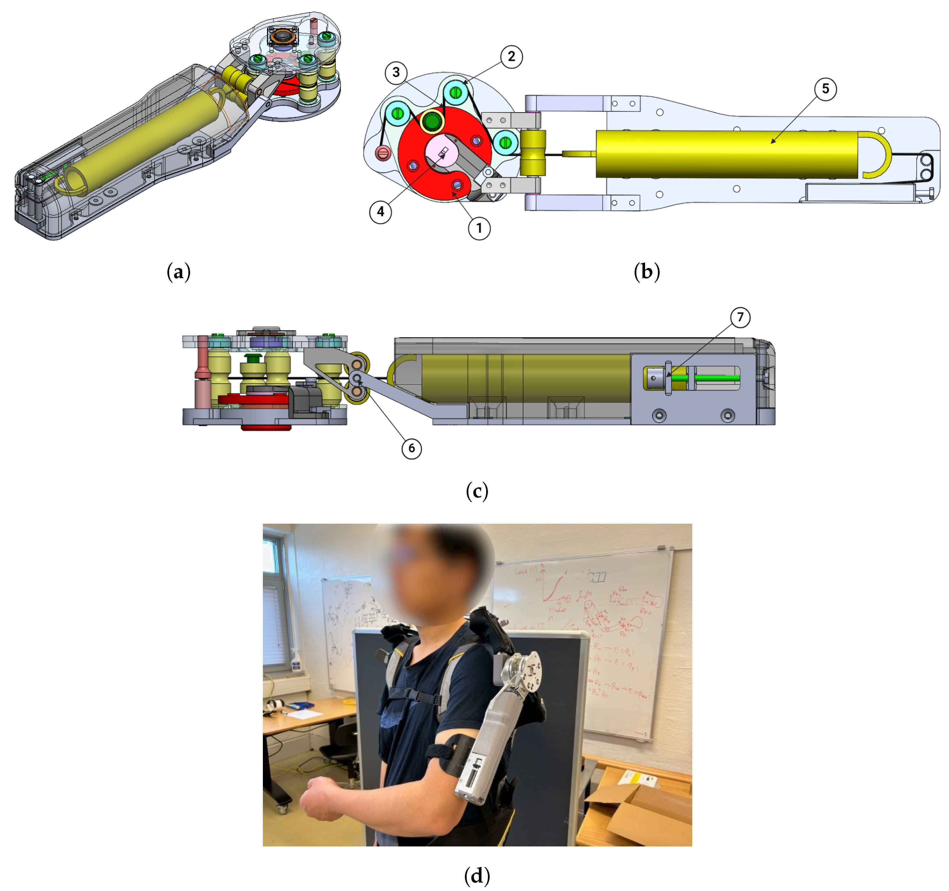
3.2. Prototype Development

Using the optimal parameters obtained, a prototype of the shoulder exoskeleton was developed. Figure 5a–c show the CAD model of the exoskeleton. An encoder was included in the design for angle recording.
Furthermore, to be adaptive to different users and assistance requirements, a manual adjusting module has been designed to change the pretension force of the spring, enabling adjustable assistance levels. The prototype, mounted on a frame manufactured by Skelex Inc. and worn by the lead author, is shown in Figure 5d.
Table 2 outlines the key specifications of the exoskeleton. In addition to the shoulder movement in sagittal plane, the exoskeleton allows shoulder movement in frontal and transverse planes, thus facilitating shoulder motions in all three DOFs.

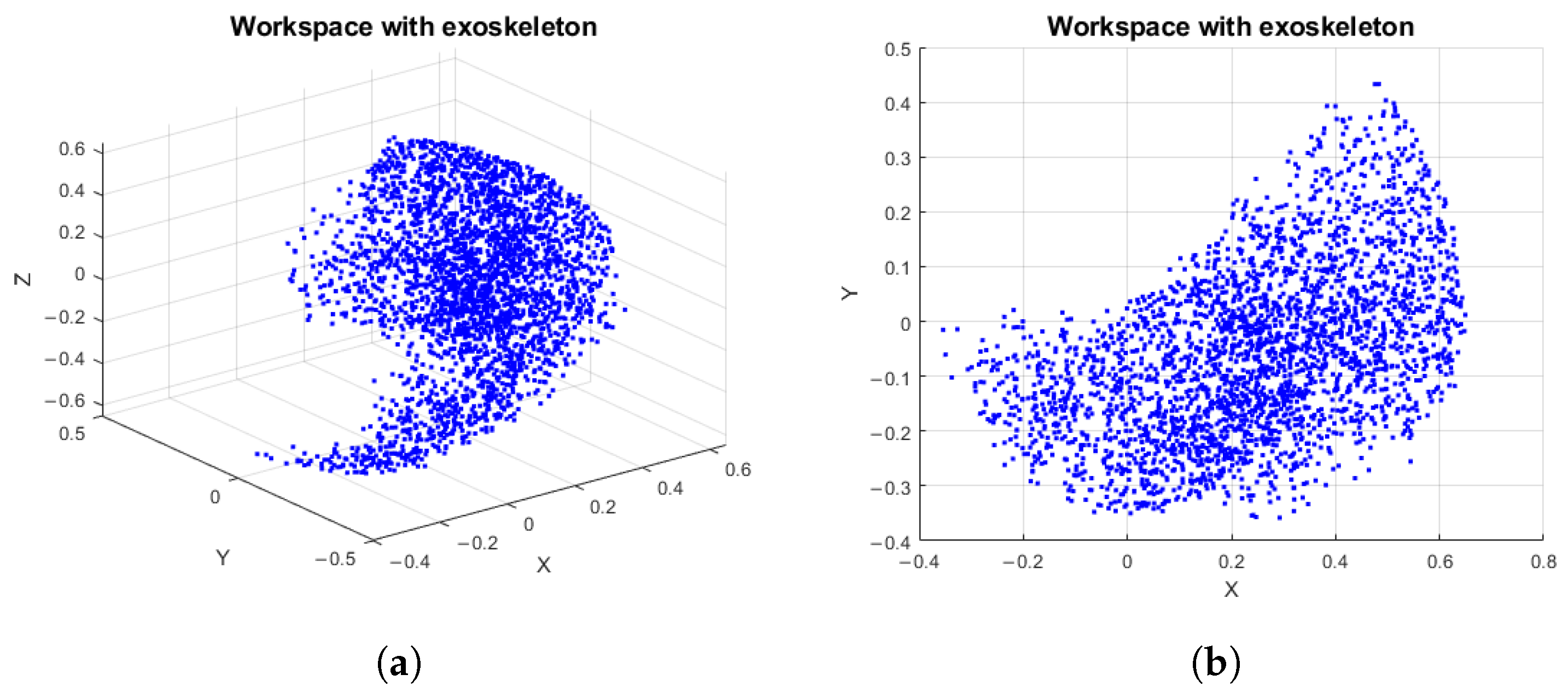
4. Workspace Analysis of the Exoskeleton

For the developed exoskeleton, the workspace of the exoskeleton is analyzed to ensure the necessary range of motion for various industrial tasks. Denavit–Hartenberg (DH) is adopted for this purpose. To simplify the calculation, the shoulder joint is modeled as a spherical joint, and the elbow pronation/supination are ignored. The DH parameters are summarized in Table 3.
Here, L u and L f represent the length of the upper arm and forearm, respectively. The ranges of θ 1 , θ 2 , and θ 3 are the angles of extension/flexion, abduction/adduction, and internal/external rotation, respectively, as shown in Table 2. θ 4 is in the range of ( 0 , 153 ° ) , which is the angle of elbow flexion/extension. The transformation matrices are readily obtained using the DH parameters:
A i = cos ( θ i ) sin ( θ i ) cos ( α i ) sin ( θ i ) sin ( α i ) a i cos ( θ i ) sin ( θ i ) cos ( θ i ) cos ( α i ) cos ( θ i ) sin ( α i ) a i sin ( θ i ) 0 sin ( α i ) cos ( α i ) d i 0 0 0 1
The overall transformation matrix from the base frame (human trunk) to the end-effector (human hand) frame can be expressed as follows:
T = A 1 · A 2 · A 3 · A 4 = R P 0 1
where P is the reaching position of the human hand. The Monte Carlo sampling method is used to generate pseudo-random numbers between 0 and 1, adhering to a uniform distribution. Each sampling produces a set of values for each joint [47]. The arm motion values generated by sampling pseudo-random numbers can be expressed as follows:
θ i j = θ i min + ( θ i max θ i min ) · r a n d ( N , 1 )
where r a n d ( N , 1 ) represents the pseudo-random number in the range of ( 0 , 1 ) complying with the uniform distribution. N is the sampling time, which is set to 3000 in this simulation. Figure 6 shows the workspace’s point cloud of the human arm with the exoskeleton. Compared with the results of the workspace analysis for the human arm in [48], it can be concluded that the workspace of the arm is not restricted by the shoulder exoskeleton for general industrial tasks.

5. Performance Evaluation of the Exoskeleton

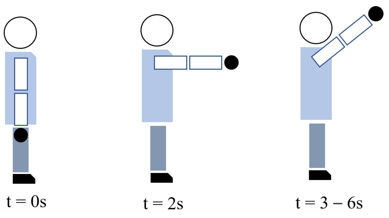
5.1. Experimental Protocol
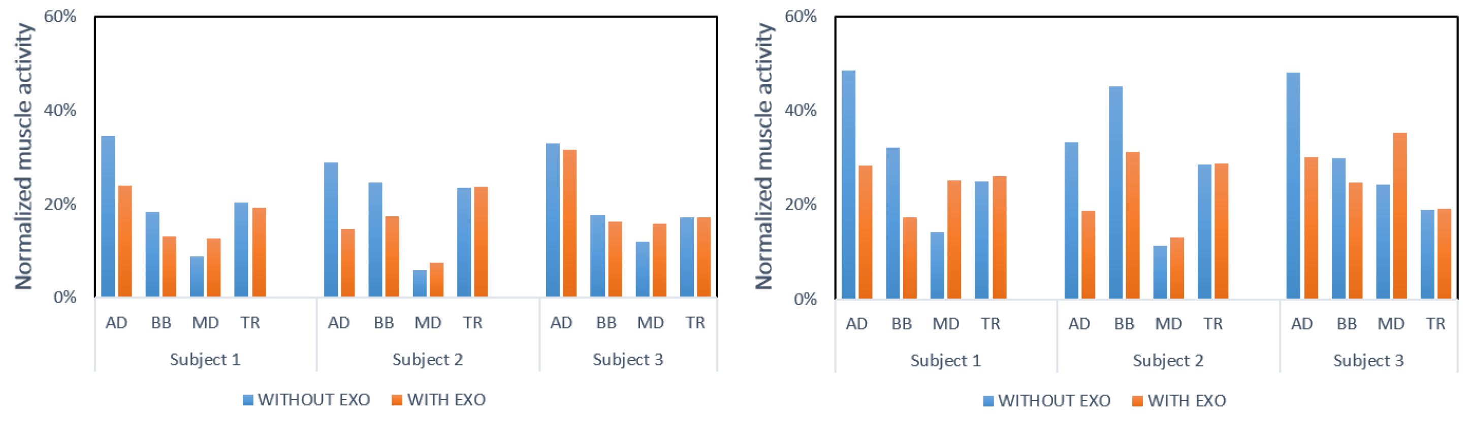
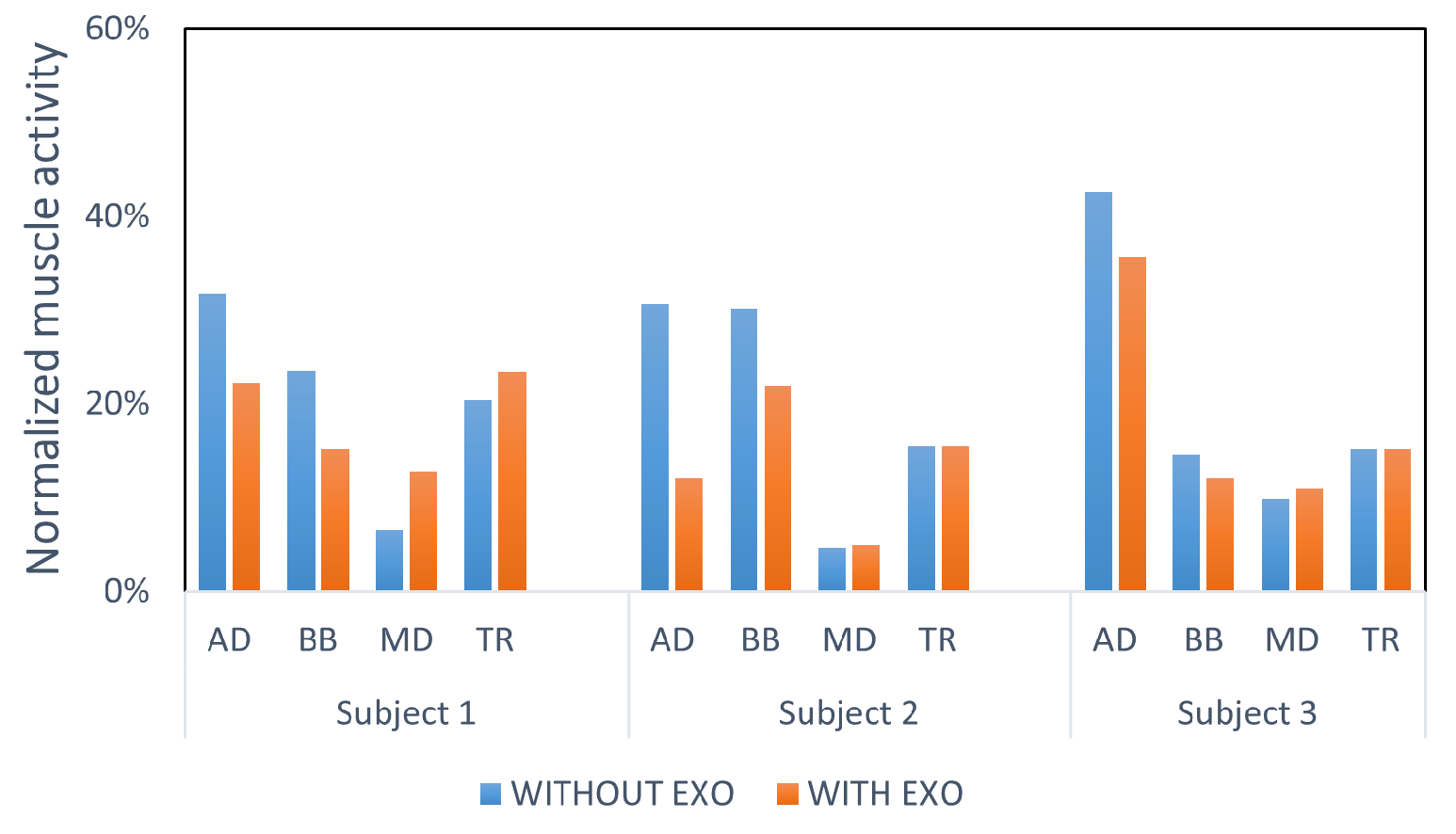
Experiments were conducted on the prototype at the Exoskeleton Lab, Aalborg University, Denmark. This study involved three right-handed male participants aged 25–30, none with a recent history of musculoskeletal disorders. The participants provided written informed consent before the study. Prior to the experimental trials, the participants engaged in a ten-minute training session to familiarize themselves with the exoskeleton and load lifting tasks. During this session, adjustments were made to the exoskeleton’s mounting interface to ensure maximum comfort.
Electromyographic (EMG) signals were utilized to assess the exoskeleton’s performance. EMG data were captured using the FREEEMG system (BTS S.p.A, MI, Italy). This study focused on the activity of four shoulder-related muscles: the upper trapezius (TR), biceps brachii (BB), and the anterior and middle deltoids (AD and MD). Electrode placement followed the guidelines recommended by Cram [49]. Figure 7 illustrates the placement of the electrodes.
To evaluate the exoskeleton’s performance, both static and dynamic load lifting experiments were conducted. The maximum voluntary contractions (MVCs) of the aforementioned muscles were recorded for each participant prior to the experiments.
In the static load lifting experiment depicted in Figure 8, the participants were instructed to hold a 2 kg weight at 90 and 135 degrees, both with and without the exoskeleton, for 10 s in each of five trials. To prevent muscle fatigue, the participants rested for 3 min between trials.
In the dynamic load lifting experiment shown in Figure 9, the participants lifted a 2 kg weight from 0 to 135 degrees, both with and without the exoskeleton, for five trials. Upon reaching 135 degrees, they maintained the position for 3 s. Programmed voice guidance was used to instruct the participants while performing these tasks. To prevent muscle fatigue, the participants rested for 3 min between trials.

5.2. Results

The EMG signals were sampled at a rate of 1000 Hz. Initially, the raw EMG signals were filtered using a third-order bandpass Butterworth filter with a passband of 20–450 Hz, followed by full-wave rectification. Subsequently, the signals were processed using a lowpass filter with a cutoff frequency of 10 Hz. Figure 10 presents an example of both the raw and processed EMG signals from one trial of the static load lifting experiment.
All the EMG signals were then normalized to the MVC. The mean normalized muscle activation for the relevant muscles was extracted for both the static and dynamic load lifting tasks.
Figure 11 and Figure 12 display the normalized muscle activation during the static and dynamic load lifting experiments for the three subjects, respectively. The average reductions in muscle activation with and without the exoskeleton across the different tasks are summarized in Table 4. It is evident that the muscle activation in the anterior deltoids and biceps brachii was significantly reduced across all the tasks, particularly for the overhead lifting tasks, such as load lifting at 135 degrees, both in the static and dynamic conditions.
In addition to the anterior deltoids and biceps brachii, which are involved in shoulder flexion, the muscle activities of the upper part of the trapezius and middle deltoids were also assessed to evaluate the potential side effects of the exoskeleton. The results indicated that the exoskeleton had no significant impact on the upper trapezius, which shows that the exoskeleton did not restrict the elevation of the scapla.
In our recent work [50], the Skelex 360 exoskeleton was evaluated using a series of tasks in a controlled laboratory environment. Table 5 shows the muscle activation reduction results in the box moving task. The posterior deltoids (PDs) are the additional muscles involved in the experiment. Although one muscle involved in the evaluation differed, the overall methodology and conditions for the box moving task are comparable.
Compared to the Skelex 360 exoskeleton, our proposed exoskeleton has a larger muscle activity reduction in the anterior deltoids and biceps brachii. However, different from Skelex 360, all of the subjects experienced impedance in the middle deltoids with our proposed exoskeleton, likely due to the exoskeleton’s weight. Furthermore, misalignment between the human body and the exoskeleton may restrict free movement. Future improvements could involve integrating quasi-passive actuation to mitigate impedance [51], for which human impedance detection and human–robot interaction modulations can be included [52]. Additionally, employing a unique parallel structure could potentially eliminate misalignment concerns [53].

6. Discussion and Conclusions

In this work, we designed and evaluated a portable passive shoulder exoskeleton based on a variable stiffness mechanism to assist workers in industrial applications. The test results indicated that the exoskeleton effectively reduced the muscle activities in the anterior deltoids and biceps brachii, particularly during overhead tasks such as static load lifting at 135°. The reduction in muscle activation for load lifting position at 90° was decreased. This suggests its potential as a valuable tool for alleviating muscle strain among workers. However, there was an increase in the muscle activities in the middle deltoids. To address this, optimization strategies such as reducing weight through topology optimization and minimizing misalignment through ergonomic design could be implemented.
Additionally, considering the weight function’s emphasis on the position at β = 110 ° and α = 47 ° , further improvements can be made by adding an adjustment module to customize optimal working positions. This would enhance the exoskeleton’s adaptability to a wider range of tasks.
A workspace analysis revealed that the exoskeleton provided a sufficient workspace for general manual handling tasks, making it suitable for industrial applications. However, when no payload is present, the subjects may need to exert effort to overcome the torque provided by the exoskeleton. Introducing a clutch mechanism to disengage assistance when walking without a payload could enhance usability.
Future research could focus on assessing the feasibility of implementing the exoskeleton in real-world work environments and further optimizing its design for improved comfort and adaptability.

Author Contributions

Conceptualization, Y.Z., F.B. and S.B.; methodology, F.B. and Y.Z.; validation, Y.Z. and F.B.; software, Y.Z. and F.B.; formal analysis, Y.Z. and F.B; writing—original draft preparation, Y.Z. and F.B.; writing—review and editing, S.B. and M.S.; supervision, S.B.; project administration, S.B. and M.S. All authors have read and agreed to the published version of the manuscript.

Funding

This work was partly supported by the Independent Research Fund Denmark (DFF) through the VIEXO project and the EU Interreg North Sea Region project EXSKALLERATE.

Data Availability Statement

The raw data supporting the conclusions of this article will be made available by the corresponding author on request.

Conflicts of Interest

The authors declare no conflicts of interest.

References

  1. Gull, M.A.; Bai, S.; Bak, T. A review on design of upper limb exoskeletons. Robotics 2020, 9, 16. [Google Scholar] [CrossRef]
  2. Qiu, S.; Pei, Z.; Wang, C.; Tang, Z. Systematic review on wearable lower extremity robotic exoskeletons for assisted locomotion. J. Bionic Eng. 2023, 20, 436–469. [Google Scholar] [CrossRef]
  3. Massardi, S.; Rodriguez-Cianca, D.; Pinto-Fernandez, D.; Moreno, J.C.; Lancini, M.; Torricelli, D. Characterization and evaluation of human–exoskeleton interaction dynamics: A review. Sensors 2022, 22, 3993. [Google Scholar] [CrossRef] [PubMed]
  4. Steinhilber, B.; Luger, T.; Schwenkreis, P.; Middeldorf, S.; Bork, H.; Mann, B.; von Glinski, A.; Schildhauer, T.A.; Weiler, S.; Schmauder, M.; et al. The use of exoskeletons in the occupational context for primary, secondary, and tertiary prevention of work-related musculoskeletal complaints. IISE Trans. Occup. Ergon. Hum. Factors 2020, 8, 132–144. [Google Scholar] [CrossRef] [PubMed]
  5. Govaerts, R.; Tassignon, B.; Ghillebert, J.; Serrien, B.; De Bock, S.; Ampe, T.; El Makrini, I.; Vanderborght, B.; Meeusen, R.; De Pauw, K. Prevalence and incidence of work-related musculoskeletal disorders in secondary industries of 21st century Europe: A systematic review and meta-analysis. BMC Musculoskelet. Disord. 2021, 22, 1–30. [Google Scholar] [CrossRef] [PubMed]
  6. Altundaş Hatman, E.; Öngel, F.S.; Yavuz, M.E.; Gülenç, N. Work-related diseases and risk factors associated with work-related musculoskeletal disorders among unionized metal industry workers: A cross-sectional study. Int. J. Occup. Saf. Ergon. 2024, 30, 194–204. [Google Scholar] [CrossRef] [PubMed]
  7. Ayub, Y.; Shah, Z. Assessment of work related musculoskeletal disorders in manufacturing industry. J. Ergon. 2018, 8, 1–5. [Google Scholar] [CrossRef]
  8. Nur, N.M.; Dawal, S.Z.; Dahari, M. The prevalence of work related musculoskeletal disorders among workers performing industrial repetitive tasks in the automotive manufacturing companies. In Proceedings of the 2014 International Conference on Industrial Engineering and Operations Management, Bali, Indonesia, 7–9 January 2014; pp. 1–8. [Google Scholar]
  9. Voilqué, A.; Masood, J.; Fauroux, J.; Sabourin, L.; Guezet, O. Industrial exoskeleton technology: Classification, structural analysis, and structural complexity indicator. In Proceedings of the 2019 Wearable Robotics Association Conference (WearRAcon), Scottsdale, AZ, USA, 25–27 March 2019; pp. 13–20. [Google Scholar]
  10. Luger, T.; Bär, M.; Seibt, R.; Rieger, M.A.; Steinhilber, B. Using a back exoskeleton during industrial and functional tasks—Effects on muscle activity, posture, performance, usability, and wearer discomfort in a laboratory trial. Hum. Factors 2023, 65, 5–21. [Google Scholar] [CrossRef] [PubMed]
  11. Chang, Y.F.; Yeh, C.M.; Huang, S.L.; Ho, C.C.; Li, R.H.; Wang, W.H.; Tang, F.C. Work ability and quality of life in patients with work-related musculoskeletal disorders. Int. J. Environ. Res. Public Health 2020, 17, 3310. [Google Scholar] [CrossRef] [PubMed]
  12. Jan de, K.; Paul, V.; Jacqueline, S.; Georgios, R.; Martin, C.; Kees, P.; Pim van, D.; Isusi, I. Work-Related Musculoskeletal Disorders: Prevalence, Costs and Demographics in the EU; Publications Office: Luxembourg, 2019; p. 20. [Google Scholar] [CrossRef]
  13. Ding, S.; Narayan, A.; Reyes, F.A.; Han, S.; Yu, H. Design and control of a novel active shoulder exoskeleton for overhead work assistance. IEEE/ASME Trans. Mechatron. 2024, 1–10. [Google Scholar] [CrossRef]
  14. Li, Y.; Guan, X.; Han, X.; Tang, Z.; Meng, K.; Shi, Z.; Penzlin, B.; Yang, Y.; Ren, J.; Yang, Z.; et al. Design and preliminary validation of a lower limb exoskeleton with compact and modular actuation. IEEE Access 2020, 8, 66338–66352. [Google Scholar] [CrossRef]
  15. Pirjade, Y.; Londhe, D.; Patwardhan, N.; Kotkar, A.; Shelke, T.; Ohol, S. Design and fabrication of a low-cost human body lower limb exoskeleton. In Proceedings of the 6th International Conference on Mechatronics and Robotics Engineering (ICMRE), IEEE, Barcelona, Spain, 12–15 February 2020; pp. 32–37. [Google Scholar]
  16. Inose, H.; Mohri, S.; Yamada, Y.; Nakamura, T.; Yokoyama, K.; Kikutani, I. Development of a lightweight power-assist suit using pneumatic artificial muscles and balloon-amplification mechanism. In Proceedings of the 2016 14th International Conference on Control, Automation, Robotics and Vision (ICARCV), Phuket, Thailand, 13–15 November 2016; pp. 1–6. [Google Scholar]
  17. Porter, A.P.; Marchesini, B.; Potryasilova, I.; Rossetto, E.; Newman, D.J. Soft exoskeleton knee prototype for advanced space suits and planetary exploration. In Proceedings of the 2020 IEEE Aerospace Conference, Big Sky, MT, USA, 7–14 March 2020; pp. 1–13. [Google Scholar]
  18. Xu, M.; Wang, G.; Rong, C. Fiber-reinforced flexible joint actuator for soft arthropod robots. Sens. Actuators Phys. 2022, 340, 113522. [Google Scholar] [CrossRef]
  19. Otten, A.; Voort, C.; Stienen, A.; Aarts, R.; van Asseldonk, E.; van der Kooij, H. LIMPACT: A hydraulically powered self-aligning upper limb exoskeleton. IEEE/ASME Trans. Mechatron. 2015, 20, 2285–2298. [Google Scholar] [CrossRef]
  20. Kim, H.; Shin, Y.J.; Kim, J. Design and locomotion control of a hydraulic lower extremity exoskeleton for mobility augmentation. Mechatronics 2017, 46, 32–45. [Google Scholar] [CrossRef]
  21. Noda, T.; Morimoto, J. Development of upper-extremity exoskeleton driven by pneumatic cylinder toward robotic rehabilitation platform for shoulder elevation. In Proceedings of the 2015 IEEE International Conference on Rehabilitation Robotics (ICORR), Singapore, 11–14 August 2015; pp. 496–501. [Google Scholar]
  22. Holl, E. New optimized mechanism for linking a hydraulic actuator to the elbow joint of an upper arm exoskeleton. J. Test. Eval. 2022, 50, 2400–2409. [Google Scholar] [CrossRef]
  23. Toxiri, S.; Näf, M.B.; Lazzaroni, M.; Fernández, J.; Sposito, M.; Poliero, T.; Monica, L.; Anastasi, S.; Caldwell, D.G.; Ortiz, J. Back-support exoskeletons for occupational use: An overview of technological advances and trends. IISE Trans. Occup. Ergon. Hum. Factors 2019, 7, 237–249. [Google Scholar] [CrossRef]
  24. de Miguel-Fernández, J.; Lobo-Prat, J.; Prinsen, E.; Font-Llagunes, J.M.; Marchal-Crespo, L. Control strategies used in lower limb exoskeletons for gait rehabilitation after brain injury: A systematic review and analysis of clinical effectiveness. J. Neuroeng. Rehabil. 2023, 20, 23. [Google Scholar] [CrossRef]
  25. Pérez Vidal, A.F.; Rumbo Morales, J.Y.; Ortiz Torres, G.; Sorcia Vázquez, F.d.J.; Cruz Rojas, A.; Brizuela Mendoza, J.A.; Rodríguez Cerda, J.C. Soft Exoskeletons: Development, Requirements, and Challenges of the Last Decade. Actuators 2021, 10, 166. [Google Scholar] [CrossRef]
  26. Ding, S.; Francisco, A.R.; Li, T.; Yu, H. A novel passive shoulder exoskeleton for assisting overhead work. Wearable Technol. 2023, 4, e7. [Google Scholar] [CrossRef]
  27. Asgari, M.; Phillips, E.A.; Dalton, B.M.; Rudl, J.L.; Crouch, D.L. Design and preliminary evaluation of a wearable passive cam-based shoulder exoskeleton. J. Biomech. Eng. 2022, 144, 111002. [Google Scholar] [CrossRef]
  28. Kim, J.; Kim, J.; Jung, Y.; Lee, D.; Bae, J. A passive upper limb exoskeleton with tilted and offset shoulder joints for assisting overhead tasks. IEEE/ASME Trans. Mechatron. 2022, 27, 4963–4973. [Google Scholar] [CrossRef]
  29. Rossini, M.; De Bock, S.; van der Have, A.; Flynn, L.; Rodriguez-Cianca, D.; De Pauw, K.; Lefeber, D.; Geeroms, J.; Rodriguez-Guerrero, C. Design and evaluation of a passive cable-driven occupational shoulder exoskeleton. IEEE Trans. Med. Robot. Bionics 2021, 3, 1020–1031. [Google Scholar] [CrossRef]
  30. Karfidova, A.; Vasilyev, M.; Morozova, I. Modernization of an industrial passive exoskeleton prototype for lower extremities using rapid prototyping technologies. IOP Conf. Ser. Mater. Sci. Eng. 2020, 971, 052049. [Google Scholar] [CrossRef]
  31. Eguchi, Y.; Kadone, H.; Suzuki, K. Standing mobility device with passive lower limb exoskeleton for upright locomotion. IEEE/ASME Trans. Mechatron. 2018, 23, 1608–1618. [Google Scholar] [CrossRef]
  32. Hull, J.; Turner, R.; Asbeck, A.T. Design and preliminary evaluation of two tool support arm exoskeletons with gravity compensation. Mech. Mach. Theory 2022, 172, 104802. [Google Scholar] [CrossRef]
  33. Lee, H.H.; Yoon, K.T.; Lim, H.H.; Lee, W.K.; Jung, J.H.; Kim, S.B.; Choi, Y.M. A novel passive shoulder exoskeleton using link chains and magnetic spring joints. IEEE Trans. Neural Syst. Rehabil. Eng. 2024, 32, 708–717. [Google Scholar] [CrossRef]
  34. Rodríguez-León, J.F.; Chaparro-Rico, B.D.; Cafolla, D.; Lago, F.; Castillo-Castañeda, E.; Carbone, G. Design of a novel exoskeleton with passive magnetic spring self-locking and spine lateral balancing. J. Bionic Eng. 2024, 21, 236–255. [Google Scholar] [CrossRef]
  35. Vallée, A. Exoskeleton technology in nursing practice: Assessing effectiveness, usability, and impact on nurses’ quality of work life, a narrative review. BMC Nurs. 2024, 23, 156. [Google Scholar] [CrossRef]
  36. Coccia, A.; Capodaglio, E.M.; Amitrano, F.; Gabba, V.; Panigazzi, M.; Pagano, G.; D’Addio, G. Biomechanical effects of using a passive exoskeleton for the upper limb in industrial manufacturing activities: A pilot study. Sensors 2024, 24, 1445. [Google Scholar] [CrossRef]
  37. Skelex. Skelex Products. Available online: https://www.skelex.com/products (accessed on 24 July 2024).
  38. Hyundai Robotics. Wearable Robot VEX. Available online: https://robotics.hyundai.com/en/unveiled-robots/wearable/vex.do (accessed on 24 July 2024).
  39. Immo Denmark. Paexo Shoulder. Available online: https://immodenmark.dk/produkter/paexo-shoulder/ (accessed on 24 July 2024).
  40. Orthexo. Ekso Evo Upper Body Industrial Exoskeleton from Ekso Bionics. 2023. Available online: https://orthexo.de/en/exoskeletons/industrial-exoskeletons/ekso-evo/ (accessed on 24 July 2024).
  41. Van Engelhoven, L.; Poon, N.; Kazerooni, H.; Rempel, D.; Barr, A.; Harris-Adamson, C. Experimental evaluation of a shoulder-support exoskeleton for overhead work: Influences of peak torque amplitude, task, and tool mass. IISE Trans. Occup. Ergon. Hum. Factors 2019, 7, 250–263. [Google Scholar] [CrossRef]
  42. Balser, F.; Desai, R.; Ekizoglou, A.; Bai, S. A novel passive shoulder exoskeleton designed with variable stiffness mechanism. IEEE Robot. Autom. Lett. 2022, 7, 2748–2754. [Google Scholar] [CrossRef]
  43. Li, Z.; Bai, S. A novel revolute joint of variable stiffness with reconfigurability. Mech. Mach. Theory 2019, 133, 720–736. [Google Scholar] [CrossRef]
  44. Li, Z.; Bai, S.; Madsen, O.; Chen, W.; Zhang, J. Design, modeling and testing of a compact variable stiffness mechanism for exoskeletons. Mech. Mach. Theory 2020, 151, 103905. [Google Scholar] [CrossRef]
  45. Ye, Y. Interior Point Algorithms: Theory and Analysis; John Wiley & Sons: Hoboken, NJ, USA, 2011. [Google Scholar]
  46. Male-Female-Population-Denmark. Available online: https://www.statista.com/statistics/1008574/male-female-population-denmark-1769-2020 (accessed on 11 April 2023).
  47. Li, J.; Zhao, F.; Li, X.; Li, J. Analysis of robotic workspace based on Monte Carlo method and the posture matrix. In Proceedings of the 2016 IEEE International Conference on Control and Robotics Engineering (ICCRE), Singapore, 2–4 April 2016; pp. 1–5. [Google Scholar]
  48. Liao, Z.; Chen, B.; Qian, Z.; Chang, T.; Bai, D.; Liu, K.; Xu, J. Collaborative workspace design of supernumerary robotic limbs base on multi-objective optimization. J. Braz. Soc. Mech. Sci. Eng. 2023, 45, 354. [Google Scholar] [CrossRef]
  49. Criswell, E. Cram’s Introduction to Surface Electromyography; Jones & Bartlett Publishers: Burlington, MA, USA, 2010. [Google Scholar]
  50. Musso, M.; Oliveira, A.S.; Bai, S. Influence of an upper limb exoskeleton on muscle activity during various construction and manufacturing tasks. Appl. Ergon. 2024, 114, 104158. [Google Scholar] [CrossRef]
  51. Arora, A.; McIntyre, J.R. Quasi-passive lower and upper extremity robotic exoskeleton for strengthening human locomotion. Sustainable Innovation: Trends in Marketing and Management; Springer: Cham, Switzerland, 2020; pp. 1–14. [Google Scholar]
  52. Zhu, Y.; Bai, S. Human Compatible Stiffness Modulation of a Novel VSA for Physical Human-Robot Interaction. IEEE Robot. Autom. Lett. 2023, 8, 3023–3030. [Google Scholar] [CrossRef]
  53. Wang, X.; Guo, S.; Qu, B.; Bai, S. Design and experimental verification of a hip exoskeleton based on human–machine dynamics for walking assistance. IEEE Trans. Hum.-Mach. Syst. 2023, 53, 85–97. [Google Scholar] [CrossRef]
Figure 1. The basic concept of the VSM. (a) The special case of the four-bar linkage, (b) the implementation of the VSM with pulleys and cable, (c) torque generator concept with VSM, where the torque is generated due to the restoring force of the spring.
Robotics 13 00120 g001
Figure 2. Torque distribution of the VSM with respect to pretension force and deflection angle.
Robotics 13 00120 g002
Figure 3. Definition of the shoulder and elbow extension/flexion angles with a simplified model of the human arm.
Robotics 13 00120 g003
Figure 4. Torque curve with optimized parameters.
Robotics 13 00120 g004
Figure 5. Views of the shoulder exoskeleton. (a) Isometric view of the torque generator, (b) top view of the torque generator with the cover removed: (1) input plate, (2) output plate, (3) cable, (4) encoder, (5) linear spring, (c) side view with (6) free revolute joint, (7) manual adjusting module. (d) The shoulder exoskeleton worn by the lead author.
Robotics 13 00120 g005
Figure 6. Workspace point cloud of the human arm with the exoskeleton. (a) Isometric workspace, (b) workspace projected into the XOY plane. The units in these plots are meters.
Robotics 13 00120 g006
Figure 7. Placement of the electrodes.
Robotics 13 00120 g007
Figure 8. Illustration of static load lifting experiments. (a) Load lifting at 90 degrees, (b) load lifting at 135 degrees.
Robotics 13 00120 g008
Figure 9. Illustration of dynamic load lifting experiment where participants were asked to lift the load from 0 to 135 degrees and hold it at 135 degrees for 3 s.
Robotics 13 00120 g009
Figure 10. Raw and processed EMG signals recorded during the static load lifting experiment. (a) Raw EMG signal, (b) processed EMG signal.
Robotics 13 00120 g010
Figure 11. Normalized mean muscle activation during static load lifting of 90 degrees (left) and 135 degrees (right).
Robotics 13 00120 g011
Figure 12. Normalized mean muscle activation during dynamic load lifting.
Robotics 13 00120 g012
Table 1. Torque generator parameters.
l 1 l 3 k F 0
17.4 mm31.4 mm6.2 N/mm10 N
Table 2. Main specifications of the shoulder exoskeleton.
DescriptionValue
Length (without frame)58.6 mm
Width (without frame)293.8 mm
Weight (without frame)0.705 kg
Number of DOFs3
Range of extension/flexion 36 ° 178 °
Range of abduction/adduction 5 ° 45 °
Range of internal/external rotations 5 ° 81 °
Designed payload 0 5 kg
Spring modelBUFSP22-2.5-91
Table 3. DH parameters.
Link (i) θ i d i a i α i
1 θ 1 00 π 2
2 θ 2 00 π 2
3 θ 3 L u 0 π 2
4 π 2 θ 4 0 L f 0
Table 4. Averaged reduction in muscle activation during load lifting tasks.
Muscle Activation Reduction
TasksADBBMDTR
Static load lifting (90°)8.72%4.55%−3.16%0.34%
Static load lifting (135°)17.58%11.37%−7.82%−3.62%
Dynamic load lifting11.68%6.36%−2.57%−1.01%
Table 5. Average reduction in muscle activation during box moving with Skelex 360.
Muscle Activation Reduction
TaskADBBMDPD
Box moving7.65%−1.60%1.73%−2.02%
Disclaimer/Publisher’s Note: The statements, opinions and data contained in all publications are solely those of the individual author(s) and contributor(s) and not of MDPI and/or the editor(s). MDPI and/or the editor(s) disclaim responsibility for any injury to people or property resulting from any ideas, methods, instructions or products referred to in the content.

