Abstract
Humanoid robots often struggle with tasks such as lifting objects due to the complexity involved in identifying contact points, applying the correct force, and tracking task progress. We propose an integrated solution that leverages the dual-arm capability of humanoids and utilizes sensor fusion from vision and force sensors. Our system employs a computer vision algorithm to detect and characterize object properties (shape, size, position, orientation) and differentiate between parallel and non-parallel bi-manipulation tasks. The controller then identifies optimal contact points for the end effectors, generating trajectories fed into a closed-loop controller using force feedback. For parallel bi-manipulation, momentum cancellation is achieved through sensor fusion. For non-parallel surfaces, a reinforcement learning algorithm determines the appropriate lifting force to prevent slippage using only two contact points. Experimental validation on a real humanoid platform demonstrates the effectiveness of our approach in autonomously lifting objects, regardless of contact surface configuration. This advancement significantly enhances the reliability and versatility of humanoid robots in performing complex manipulation tasks, contributing to their practical deployment in human-oriented environments.
1. Introduction
In the following decades, it is expected to see robotic systems coexisting with us on a daily basis, helping to make our lives easier. These advances will improve quality of life not only by replacing unwanted day-to-day tasks such as cleaning the house, buying groceries, among other activities, etc., but also by helping elderly and disabled people to perform activities that they may be unable to accomplish currently because they involve carrying heavy weights or making a high physical effort. This growing interest is directly reflected in the increase in research projects related to humanoid service robots [1], covering a wide range of tasks: from cleaning [2] to waiter activities [3], among many other service tasks [4].
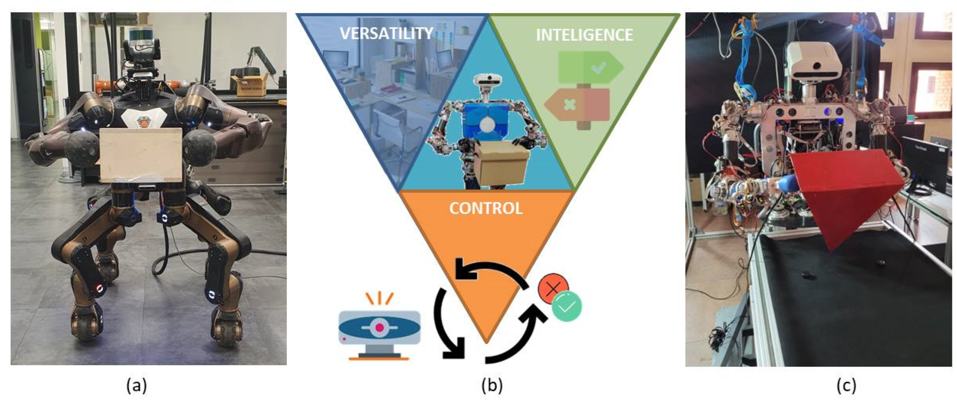
However, to finally achieve the goal of robots capable of performing activities in an autonomous mode and fully integrated into our daily lives, there is still a long way to go. We propose three main characteristics, represented in Figure 1b, to be considered as requirements for the system to perform the tasks: versatility, intelligence, and control.

Figure 1.
(a) The robot Centauro from IIT lifting a wood box. (b) Characteristics of a self-sufficient robot: versatility, intelligence, and control. (c) Humanoid robot TEO from UC3M RoboticsLab lifting a triangular parallelepiped.
Versatility: to interact in a non-structured environment, in which the common factor is the lack of standardization due to human activity. For that reason, it must be able to adapt to different scenarios and overcome obstacles [5], among other issues. Intelligence: to interact and make decisions to accomplish tasks with autonomy, by extracting relevant information and using it optimally to complete that particular activity. Finally, control regarding the task performed is necessary. Robots should be able to have enough knowledge to decide if the task performed was successful or not by using their own sensing systems, being capable of rectifying and changing parameters until the goal is achieved.
This research was developed in two phases: The first phase was started in Instituto Italiano di Tecnologia (IIT) working with the Centauro robot, shown in Figure 1a. There, the vision system to classify the different shapes as well as to characterize the objects (position, size, orientation) was developed. Also, the first bi-manipulation trajectories were implemented. Then, the research was continued in the RoboticsLab from University Carlos III of Madrid by using the humanoid robot TEO (Figure 1c). Dual-arm tasks for object lifting were improved by closing the force–position–visual loop. Also, a reinforcement learning process was implemented to help the robot lift objects with non-parallel contact faces.
Much research has focused on lifting objects with dual-arm robots applying force control [6,7,8,9,10]. However, most of them are implemented in controlled standardized environments like warehouses. Also, in many cases, previous information like shape, weight, or position is given by using QR codes. In the approach presented in this paper, the robot identifies the objects and extracts their characteristics, distinguishing between parallel and non-parallel contact. Then, it generates the approximation trajectory to make contact with the end-effectors to finally try to lift the object. Instead of performing fixed grasping as shown in Figure 2a, in which the slippery effects are completely deleted from the equation because the contact is completely rigid, the problem has been approached by pressure control, as in Figure 2b.
Figure 2.
(a) Fixed grasping blocking all object movement axes. (b) Pressure grasping. Compensating gravity force by applying lateral pressure on objects.
There are objects that are not possible to manipulate with rigid contacts due to their size. Therefore, in this paper, we focus on this kind of pressure grasping, trying to bi-manipulate the objects to prevent them from slipping. To achieve this goal, we combined information from both force and visual sensors.
The remainder of this paper is organized as follows: In Section 2, the structure of the application is explained. Section 3 describes the vision processing steps to classify the shapes and acquire the object characteristics. In Section 4, the contact points to lift the objects with parallel and non-parallel surfaces are calculated. Section 5 addresses the force and vision sensor fusion. In Section 6, the experimental setup and the results for both the parallel and non-parallel objects are shown. In Section 7, a different approach to lifting objects with non-parallel faces by using reinforcement learning is developed. Finally, in Section 8, conclusions and future work are presented.
2. Autonomous Humanoid Bi-Manipulation
When we perform a task like picking an object and lifting it, we do not realize the amount of sub-processes which are running in the background. This action, which seems so simple, can be challenging for a robot due to its current level of physical and computational evolution.
Several studies in the field of neuroscience have been conducted to understand the processes that the brain follows to be able to successfully perform manipulation tasks. In [11,12], the prehension task is divided into two main components: reaching, moving the hands towards an object, supported by the feedback from visual perception; and grasping, shaping the hands with respect to the object’s properties to be able to handle it.
Taking into account those studies, in a simplified form, the process followed by humans is as follows: First of all, an existing idea of a box (or whatever the object of interest is) is required. Then, through visual perception, the object is localized and distinguished from other objects. But it is not enough to just distinguish it; to reach the object, it is also needed to obtain an accurate idea of where the object is in the space, as well as its orientation, and its size. Based on these data, the decision to pick it up is taken: if it is small, using one hand; and if it is a big object, using both arms. Therefore, the hands directly make contact with the object, adapting to its shape (reaching the position at which it is expected that the object will not spin), and in that moment, based on previous experiences where objects of similar size were lifted, force is applied. This strategy usually works, but sometimes, the object to be lifted is heavier than expected; as a consequence, it slips from the hands. So, the object has to be left lying on the surface, and then try to lift it once again by applying higher forces. Finally, the object is lifted and brought to another place.
As can be seen in Figure 3, three main blocks can be distinguished in the application: computer vision, trajectory generation and contact point calculation, and bi-manipulation control.
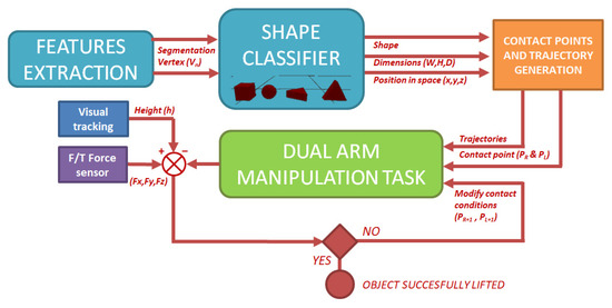
Figure 3.
Scheme of autonomous bi-manipulation application.
Through computer vision techniques, the object is segmented from the image. Then, by using a contour shape classifier (based on the space disposal of the shape vertex), the robot identifies different shapes (sphere, triangular prism, box). Once the shape has been identified, physical characteristics of the object such as position, orientation, size, etc., are calculated by mixing both RGB and depth information. The second block uses the information obtained in the previous step to calculate the contact points, as well as the trajectory to reach them. Finally, in the third block, dual-arm movements to reach contact with the object and to lift it are performed. During this step, the robot has the knowledge of whether or not it is achieving the task by fusing the feedback from the force sensors available in the end-effectors and the relation between the incremental position of the end-effectors in the vertical axis and the visual information of the position in the same axis of the upper surfaces of the objects.
It is important to highlight that to have a completely independent system capable of performing the task without any previous information or help, two key points are taken into account: On the one hand, for full autonomy to identify the object and to reach the contact points with the end-effectors, just the primitive information from the classifier to identify shapes is known by the robot. On the other hand, it has the capacity to continuously check and decide if the object has been lifted by taking advantage of the information obtained from the sensor fusion (cameras plus force sensors).
3. Shape Recognition and Characterization
One of the main pillars of the dual-arm manipulation task performed in this application is the capability of obtaining useful information to feed the manipulation step after processing the RGB and depth images acquired with the camera. Through this image processing, the pose and characteristics of the object are extracted. These data are later used to generate the trajectories to lift the box. The structure of the vision algorithm can be divided into two blocks: object segmentation to identify the shape, and characterization of the information to generate the 3D model in the space. Algorithm 1 shows the pseudo-code:
| Algorithm 1: Box characteristics (2D&3D post-processing) |
| Input: RGB image + Depth image. Output: Object shape, dimensions, volume, vertex position in space (V0(x,y,z) to V5(x,y,z)) |
| Is required: RGB + Depth camera switched on. 01: Capture (RGB + D) 02: Cascade filter 03: Canny (Img_preproc) 04: HoughLinesP (Img_preproc) //Finite lines generated. 05: FindCountours (Img_preproc) //Corner acquisition. 06: Output1: 2D Vertex (V0(X,Y) to V5(X,Y)) //Location of vertexes in 2D image. 07: ∑2D Vextex(X,Y)/n.Vertex → CoG //Calculus of the Center of Geometry (CoG). 08: for n in range(len(2D Vertex)): //For each 2D vertex. 09: acquire Depth (Vn(X,Y)) //Depth obtention. 10: if (depthValue(Vn(X,Y))==0): //Value equal zero, no depth information. 11: = CoG − Vn(X,Y) //Calculus of the pixel value increase direction. 12: Output2: Depth of 2D Vertex with perspective error. 13: Perspective Filter (Vn(X,Y) + Depth n(X,Y)). 14: Output3: 3D Vertex (V0(X,Y,Z) to V5(X,Y,Z)) //Location of vertexes in 3D space. 15: Shape classifier (3D Vertex (V0(X,Y,Z) to V5(X,Y,Z)) 16: Output 4: Object shape, CoG, volume. |
3.1. Object Segmentation (2D Shape Obtention)
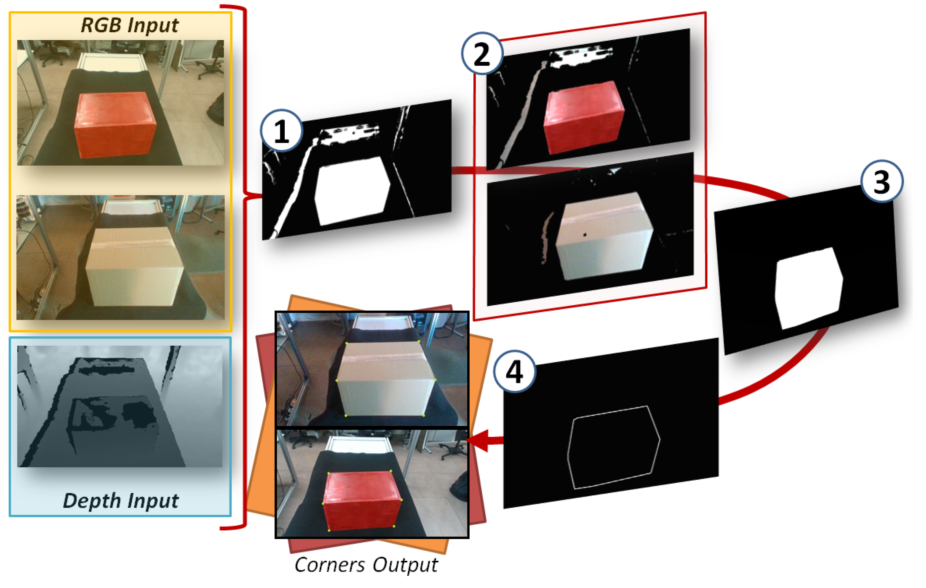
In Figure 4, the image results after the segmentation steps can be seen. These steps illustrate Algorithm 1 (lines 1 to 7). First of all, in step 1, a threshold filter to distinguish the color of the main object is applied. Then, in step 2, the threshold picture is merged with the color image, just introducing the colors of the main object. In step 3, a sequence of cascade filters to delete the noise are applied. Taking into account that the final goal is to perform a bi-manipulation task, for this task, a 1 m distance from the camera has been considered as the region of interest (ROI). The reason is that reaching objects over longer distances would imply a displacement, and this is out of the scope of this research. Therefore, following this assumption, a depth filter was applied as part of the cascade filters. The depth image is merged with the filtered RGB picture. The condition of depth plus the color condition belonging to the same blob is used to finally obtain the object of interest. Finally, in step 4, a Canny filter plus Hough lines and corner detector are applied to obtain the object corners in the RGB 2D image.

Figure 4.
Steps to obtain object corners.
3.2. Three-Dimensional Object Generation (Position in Space, Volume)
Once the corner points have been identified, it is required to extrapolate them to the 3D space. To achieve this, the pixel coordinates (X,Y) of the corners in the RGB image are used to obtain the depths in the depth image matrix also acquired by the camera. Ideally, in simulation, this task is easy, as long as there is no noise. However, in real cameras, the light spectrum affects the infrared system, creating noise and blank zones in the depth matrix. Also, there are occluded zones to the camera. As a consequence, some vertex coordinates may match this lack of information. In Figure 5a, the depth image appears with these defects (pixels in black). Therefore, to avoid the absence of information, a filter has been implemented. The depths of each vertex are extracted from the depth matrix by following the RGB coordinates. In case the depth value is equal to zero (no information), the filter extracts the Center of Geometry of the total vertex in 2D. Then, the coordinates of the vertex are displaced to that direction, until a depth value is obtained. This correction can have a minor effect when generating the object volume. However, this error has been considered and is compensated in the approach trajectory, when the robot makes contact with the object (Algorithm 1, steps 11 to 16).
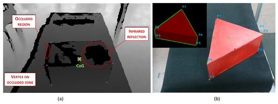
Figure 5.
(a) Noise correction in box shape after depth information acquisition. (b) Triangular prism shape identified with classified vertex.
Finally, as explained in [13], depth information obtained with the infrared sensor of the camera shows the distance from the camera to each point of the image in the space. Therefore, it is important to take into account the perspective of the visual field of the robot. The head is tilted to see the objects over the table; as a consequence, the camera is not perpendicular to the floor plane. Then, to obtain the real relation of the position of the object in reference to the robot origin coordinates, the correction already developed in previous research is applied, and the real position of the vertex in 3D space is obtained.
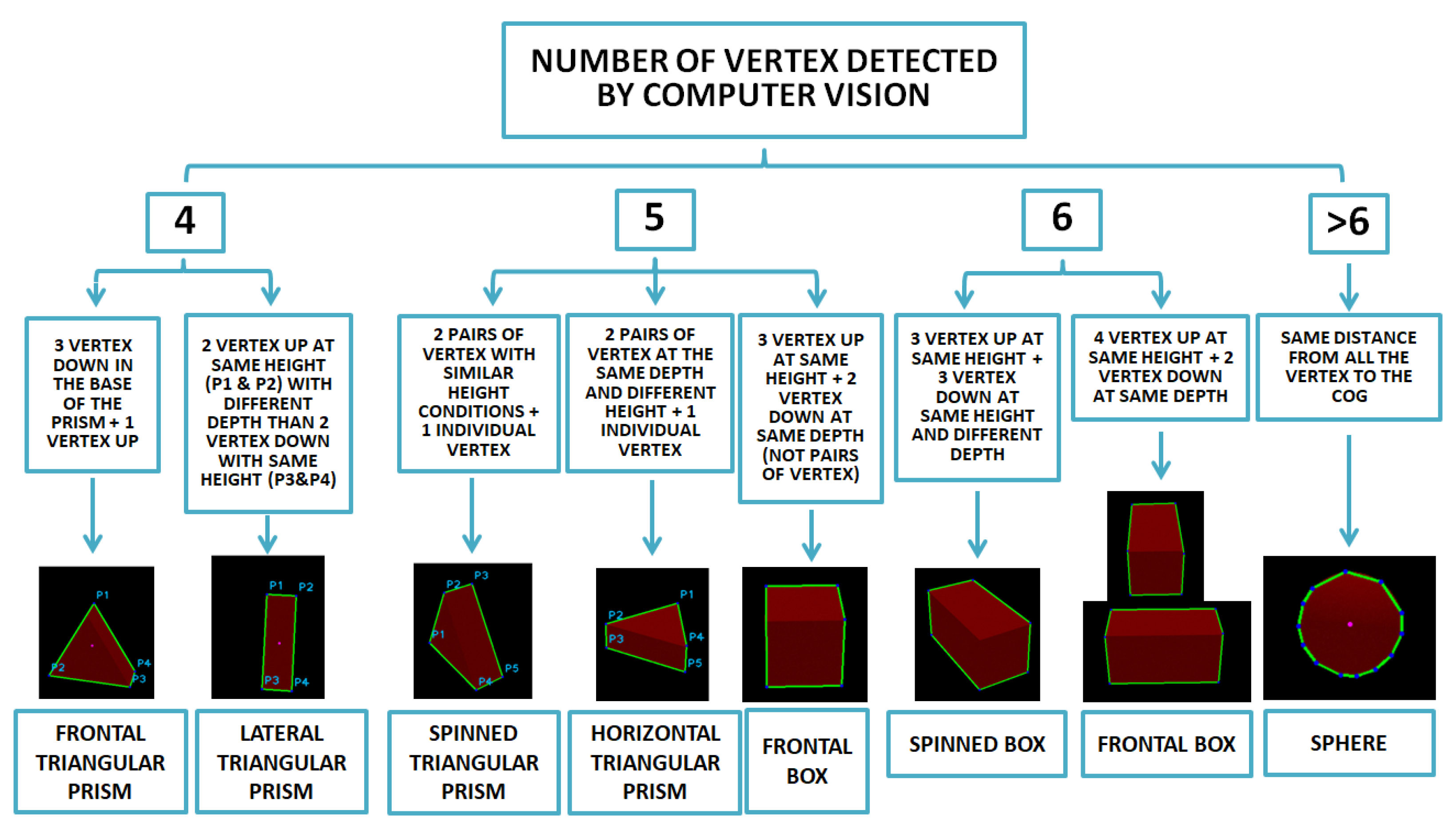
From that point, a classifier has been implemented to link the corners of the shape and generate the volume and position of the object in the space, etc. The scheme according to this classifier can be seen in Figure 6. Firstly, vertexes are distinguished between upper surfaces and down surfaces (normal axis to supporting surface). Then, taking into account the relation between lower and upper points, a second segregation is achieved by considering the distance to the robot. Once all the points have been classified as seen in Figure 5b, knowing the position, the Center of Mass (CoM) in the space of the 3D shape is calculated as well as the object volume.
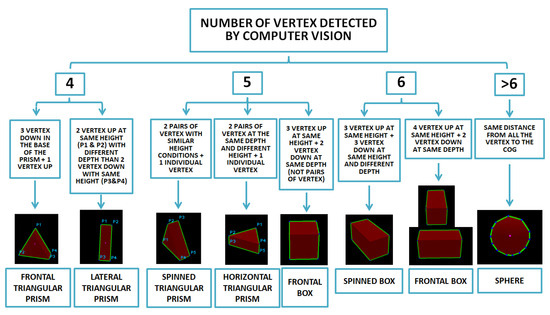
Figure 6.
Shape classifier based on number of vertexes detected and 3D position in space.
After having classified all the visual information and knowing the shape that has to be bi-manipulated, as well as the positions and orientations of the objects in space, based on the nature of the object, the robot can choose between the parallel and non-parallel bi-manipulation task.
4. Study of Grasping Points
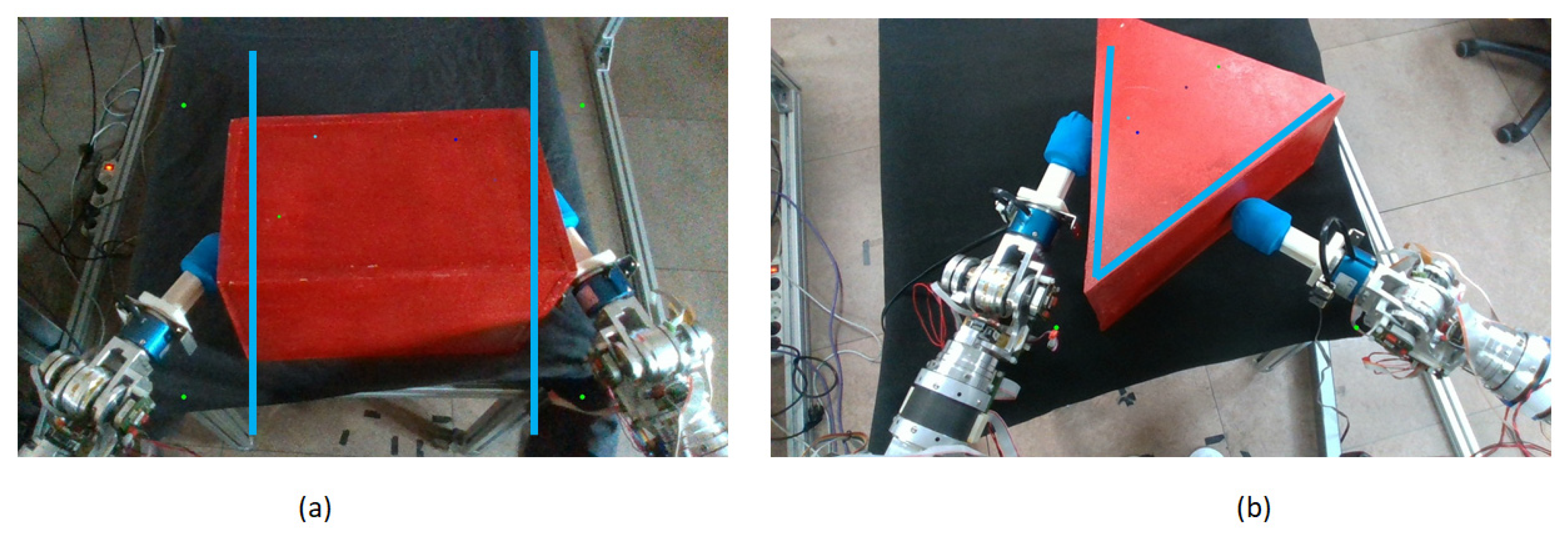
Due to the configuration of the lateral faces of the objects, the obtention of the contact points to perform the bi-manipulation task can be classified in two different cases: On one hand, there are objects with parallel faces, allowing symmetric grasping. The obtention of two contact points to cancel the moments generated by the forces exerted by each end-effector is more intuitive. These equations to find the contact points were applied in boxes and spheres (Figure 7a). On the other hand, we can find objects with non-parallel faces. In this case, finding two contact points is more complex, i.e., to obtain the momentum cancelation, factors such as the angles between both faces and the slippery have to be taken into account. Tests were performed with a triangular shape (Figure 7b), considering it as an extreme case of non-parallel faces.
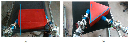
Figure 7.
(a) Parallel grasping (box). (b) Non-parallel grasping (triangle).
Several studies in which object shapes are approximated to primitive shapes such as boxes or spheres have been conducted [14,15,16]. This paper focused on the performance of dual-arm manipulation tasks in an autonomous mode, proposing different approaches between parallel and non-parallel contact surfaces. In future works, by combining the methods of primitive shapes for objects plus the steps developed in this study, the dual-arm manipulation task can be extended for a more generic range of objects with a wide range of shapes.
4.1. Parallel Grasping
The segmented objects, boxes and spheres, do not have any surface that allows for rigid grasping by using grippers. In case it was possible, a fixed contact point would be generated, avoiding any slip or movement of the manipulated object. Also, if the object was grabbed, the grasping task could be performed only by one hand.
However, as the box and sphere surfaces are smooth, the objects’ volumes are bigger than the size that can be covered by a human-sized gripper, and there is a lack of grasping points; it is necessary to perform the task working simultaneously with both arms. While generating the force, it is important to apply a pressure high enough to keep the object gripped (as a human being would do) without damaging or permanently deforming it. If the force value is not enough to keep the object lifted, a slippery movement from the end-effectors can appear. This effect can appear as a consequence of the lack of fixed links between the contact points of the object and the robot. The description of this kind of grasping task is similar to a point or surface contact-based grasping [17].
In [18], experiments were performed where subjects lifted objects with varying friction surfaces while their grip and load forces were measured, with and without finger anesthesia, to study the adaptation and coordination of these forces. The conclusion was that coordination between the grip force and the load force is crucial to avoid slipping. An adequate balance between both forces, maintaining a symmetrical and opposite force value, allows maintaining a small but sufficient safety margin to prevent falls.
Also, in the experiments in [19], it can be seen that the lifting action can be divided into a sequence of action phases—reach, load, lift, and hold—clearly differenced while measuring the grip force. The sequence of actions presented in Roland S. Johansson’s paper can be also observed in the experiments performed by the robot, showing a complete similitude between the human and robot performances.
Following these studies on the human behavior, in order to reproduce the actions with a robot and perform the box-lifting action and maintain the grasp while preventing the box from slipping, falling, or being smashed, it is necessary to localize the contact points that allow a force to be generated with both arms in such a way that the resultant force is equivalent to a virtual fixed contact [20]. So, as a consequence, both robot arms would be united by this object which would be similar to a mechanical resistance based on solid rigidity. In addition, both contact points must be placed in such a way that the moments generated by the forces applied on the object surfaces are null, thus avoiding any twist and flip effects on it. This implies that there should exist symmetrical bimanual coordination [21].
After having defined the kind of grasping task that is going to be performed by the robot, three main limiting factors can be distinguished when defining the contact zones between the end-effectors and the object: individual orientation of each end-effector in relation to the contact surface, the relation of both end-effectors’ forces to obtain the null moment and the articular limitations of the robot.
4.1.1. Force Orientation between End-Effector and Contact Surface
One of the most extended conditions to determine the orientation range of the forces applied between an object and an end-effector on a grasping task is the friction cone, represented in yellow in Figure 8.
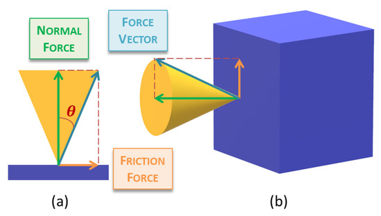
Figure 8.
Friction cone in contact point grasping task (a) 2D representation (b) 3D representation.
This cone is obtained by rotating the triangle generated by the vertex angle of θ, where θ is calculated using the arctangent of the coefficient of static friction µstc, as in (1):
θ = atan(µstc)
This angle θ defines the maximum inclination angle allowed while applying a force over a surface without the slippery effect. So, in case the force vector is inside this cone, the grasping task can be successfully performed.
4.1.2. Grasping Contact Surface (GCS) Based on Friction Cones and Null Force Moments
The condition of the friction cone allows us to delimit the angle of incidence of the force from a single end-effector with respect to the surface. However, we must take into account that our system has two arms, and therefore, the support point is double. With two support points, we are exerting two forces simultaneously on the object. Hence, it is necessary to counterbalance these forces in such a way that an undesired rotation or overturning of the object does not occur.
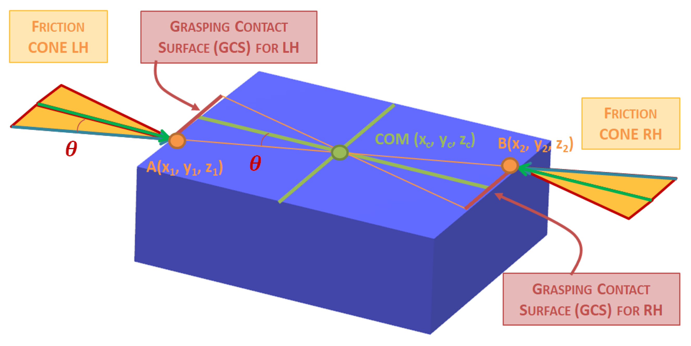
Taking the friction cone with an angle amplitude of ±θ as a reference [22], which has been obtained from the coefficient of friction, we can establish the range of action of the forces. To cancel forces, we make two assumptions: the box is a rigid or semi-rigid object and its mass is uniformly distributed. The friction cones provide contact forces that pass through the Center of Mass of the box to cancel out the forces and eliminate any torsion on the box.
We define the coordinates of the two points of contact between the robot and the box as A(x1, y1, z1) and B(x2, y2, z2), where (x, y, z) represent the coordinates in the robot’s reference system. The Center of Mass of the box is denoted as COM(xc, yc, zc), as seen in Figure 9.
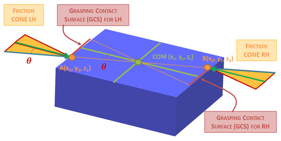
Figure 9.
Grasping Contact Surface (GCS) based on friction cones and null force moment.
Based on these assumptions, the equation relating the positions of the friction cones at the contact points for the forces to cancel out is as follows.
In (2) the sum of forces in the x-axis is shown, where the sum of the x-components of the contact forces at points A and B should be equal to zero:
FxA × cos(θA) + FxB × cos(θB) = 0
FxA is the magnitude of the force at contact point A. FxB is the magnitude of the force at contact point B. θA is the angle between the friction cone at contact point A and the robot’s x-direction. θB is the angle between the friction cone at contact point B and the robot’s x-direction.
In (3), the sum of forces in the y-axis is calculated. The sum of the y-components of the contact forces at points A and B should be equal to zero:
FyA × sin(θA) + FyB × sin(θB) = 0
In the z-axis, the sum of the vertical forces at points A and B should be equal to the weight of the box (4):
where: FzA is the vertical component of the force at contact point A. FzB is the vertical component of the force at contact point B. P is the weight of the box.
FzA + FzB = P
Finally, in order to eliminate any torsion in the box, the moment generated by the forces at points A and B, both in x-axis (5) and y-axis (6), should be equal to zero:
(y1 − yc) × FxA × cos(θA) + (y2 − yc) × FxB × cos(θB) = 0
(x1 − xc) × FxA × cos(θA) + (x2 − xc) × FxB × cos(θB) = 0
Taking into account these equations, a Grasping Contact Surface (GCS) where the end-effectors can apply the force is obtained, represented in Figure 8.
4.2. Non-Parallel Grasping
Whereas in the problem of parallel grasping, it is clear that the contact points must be found in the opposite faces of the objects, while reviewing previous works to face the manipulation of irregular shapes as a triangle, finding the contact points is not so easy. In those studies regarding hand grasping of irregular shapes [23,24,25], the task is successfully achieved by increasing the contact points to over three, taking advantage of all the hand fingers. This solution is applicable to small shapes that can be handled by one hand. However, in this research, the goal is to lift an irregular shape big enough to be handled by a humanoid robot with two robotic arms at two contact points.
To achieve this, the robot must choose to make contact with two out of the three surfaces available. In order to reduce the energy consumption, as well as to avoid reaching the articular limits of the robot, the approach followed to choose the right contact points is finding the two faces more parallel to the y-axis, as in (7):
where represents the angle between the face of the triangular shape comprised by the coordinates of vertex Vi and Vj with respect to the y axis, as in (8). The triangular prism coordinates were previously obtained through computer vision:
By using (8) the robot calculates the angles with respect to the y-axis for the three laterals of the triangular shape composed by the different vertex combinations and selecting the vertex combination that minimises the sum of the absolute differences between the angles and 90°.
Once the robot has selected the two reachable contact faces of the triangular prism, the procedure followed to find the contact points to lift the object is similar to the parallel grasping.
The first constraint taken into account to find the limit force resolution to be applied over the surface is the friction cone, which purely applied corresponds to (1). However, as it is shown in Figure 10, the faces of the triangular prism are not perpendicular to the robot, there are orientated in an angle α in relation to the coordinate axis. So, the decomposition of the friction cones for each end effector are as in (9):
where FL is the force applied by the left hand, FR the force applied by the right hand, and θ is the amplitude of the friction cone defined by (1).
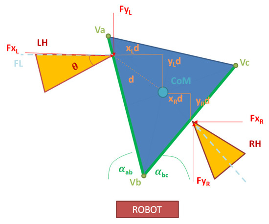
Figure 10.
Force decomposition for dual contact in non-parallel surface (triangular prism seen from above).
Based on the force decomposition for both left and right end-effectors, the robot must find two points such that the momentum after applying the force is null. Therefore, the robot must find the Center of Mass (CoM), taking into account that in a triangle, this point is coincident with its centroid “C”, which is located at the point of intersection of the medians; the robot obtains the centroid “C” (10) from the three vertexes V1(x1,y1), V2(x2,y2), and V3(x3,y3):
By taking into account the forces from both end-effectors decomposed in the x- and y-axes in (9), plus the distance from each contact point to the centroid (10), the final equation to find the points where the momentum in the x- and y-axes are null is as in (11):
To find the best combination of contact points for the end-effectors, the robot has divided both contact faces into points separated 1 mm from each other in space. Then, for each contact point for the left arm, we tested the combination of all the points for the right arm by applying Equation (11). The results were stored, and once all the possible combinations were calculated by the robot, the two points which were closer to obtaining null momentum in the x- and y-axes were selected.
5. Sensor Fusion: Force, Position and Vision Control
After obtaining the contact points, the robot proceeds to perform the lifting task. To carry it out successfully, a control system has been created that allows the robot to receive three simultaneous items of feedback [26]. Two of these pieces of information pertain to the robot’s state: the position of the end-effectors and the force it is applying to the box. The third piece of information provides knowledge of how the robot is influencing the object it is interacting with. It extracts the height of the top face of the box. This feedback can be observed in the control diagram presented in Figure 11.
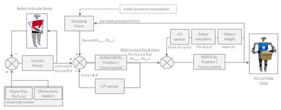
Figure 11.
Sensor fusion control scheme: force + position + visual feedback.
The relation between all the control elements seen in the previous scheme is modeled in (12):
where Flifting is the force made by the robot to lift the object. k adjusts the sensibility of the relation. is the absolute distance between both end-effectors in the axis where the pressure is applied over the object. β adjusts the influence of the height on the system. h is the height of the upper surface of the object to be lifted, and is the average of the height of both end-effectors.
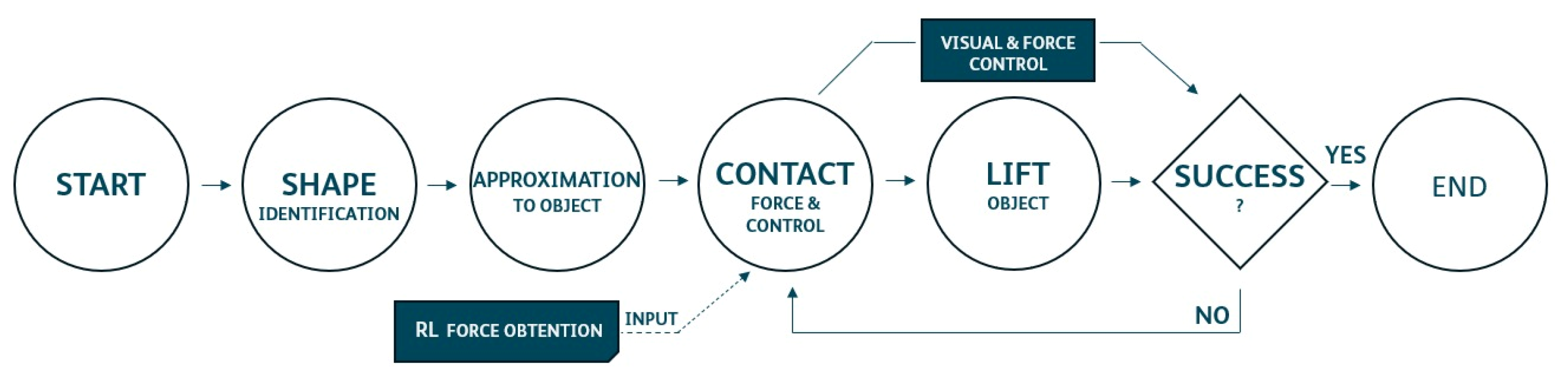
As observed in Algorithm 2, the task is performed in four steps, which are repeated until the robot detects that it has lifted the box. First, it moves to a starting position. Next, it approaches safely without making contact with the box. In the third step, it performs the displacement movement of the end-effectors until it detects that it has made contact with the box and applies the necessary force to exert pressure on it. Finally, it proceeds to lift the box.
During this lifting task, as the robot raises its arms, it continuously monitors the applied force to try to maintain it within a stable range. When it reaches the end of the lifting trajectory, it reads the height of the box. If it detects that the box is still on the table, it repeats all the previous steps while increasing the applied pressure force. If it detects that it has lifted the box to the same height as the vertical displacement of the end-effectors, the loop terminates, indicating successful completion of the task.
| Algorithm 2: Sensor fusion control loop |
| Input: End-effector horizontal position (EEPh), end-effector vertical position (EEPv), force sensors (F/T), object height (Oh) computer vision. Output: Object lifted |
| Is required: Camera + robot encoders + F/T sensors. 01: Object segmentation // Image processing 02: Grasping Contact Surface (GCS) calculus. 03: Set start pos → (XL,YL,ZL,αL,βL,γL) & (XR,YR,ZR,αR,βR,γR). // Safety pos. to start mov. 04: while ((Object height < required lift height): 05: Move EEPh to object contact. 06: while (F/T sensors < Required pressure F): //Achieve desired contact force. 07: Move EEPh to box surface → ↑ pressure. 08: while Move EEPv in z axis: //Lift the object. 09: if (20% F < F/T sensors < 120% F): //Control contact pressure. 10: Correct EEPh pressure. 11: if ((Oh or EEPz) != vertical path length): //Control F: VISION + POS. 12: ↑F(Moving EEPh). 13: Output: Object lifted. //Lift task successfully achieved. |
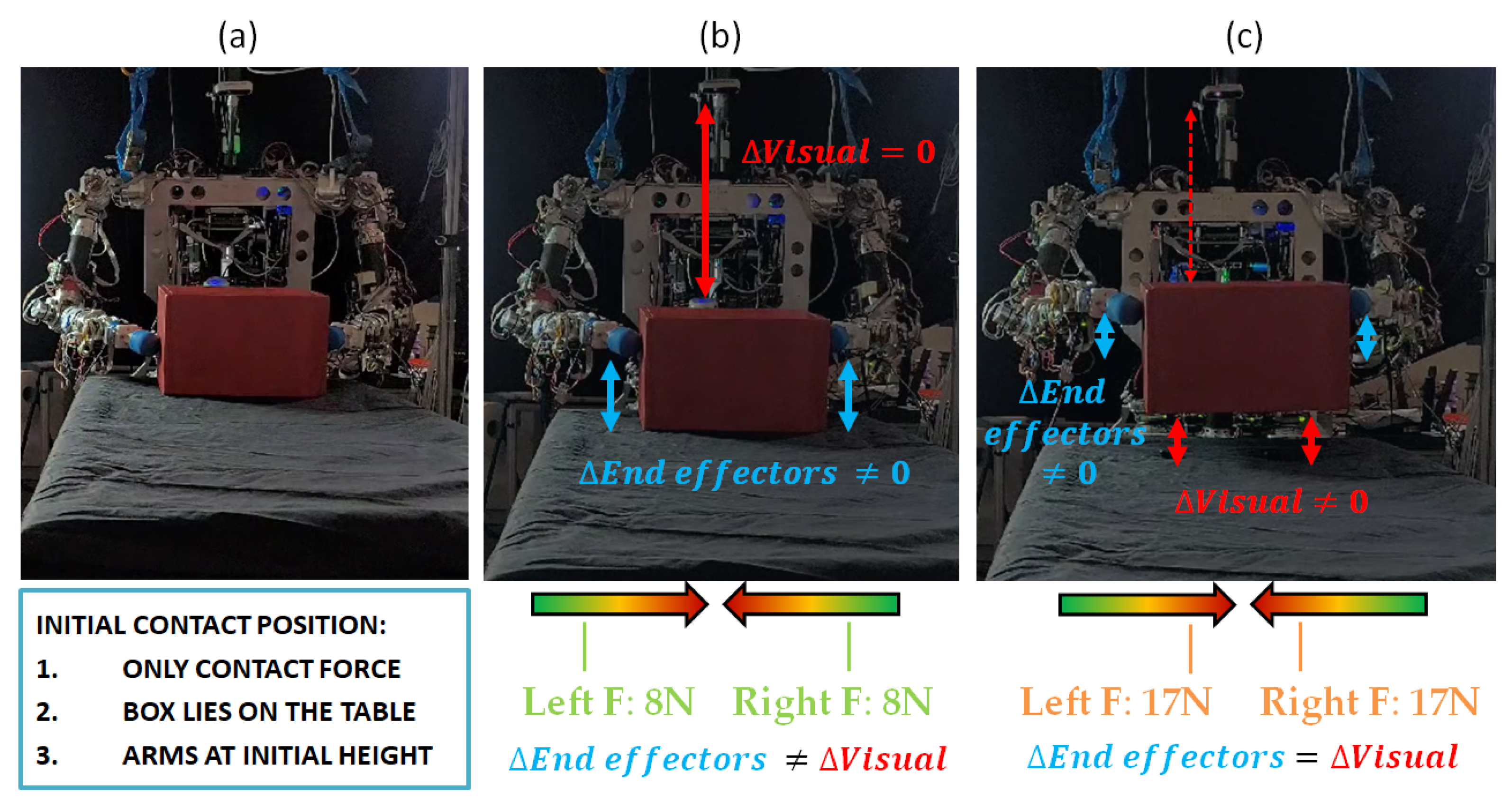
In Figure 12, the interaction between different control actors can be seen, as described in the sensor fusion control loop developed in Algorithm 2. First of all, the object is lying on a surface, and only contact forces are applied by the robot end-effectors, as shown in Figure 12a.

Figure 12.
(a) Initial state of object at rest, robot makes contact with object. (b) First attempt. Force is not high enough. Robot end-effectors increase height, but object continues lying on table. (c) Second attempt. Forces are high enough to overcome gravity and object weight. Delta of object height (visual feedback) and end-effectors’ height are similar. Object is lifted.
Then, the control loop is performed by simultaneously monitoring three online information sources. The robot sets a pressure force with both end-effectors, which is maintained constant; at the same time, while controlling the pressure force, the robot displaces the arms vertically, trying to lift the object and controlling the delta in the end-effectors’ height displacement. Meanwhile, the camera is continuously tracking the distance to the object, obtaining the height delta from the lying surface by detecting if the distance from the object to the camera is being reduced.
In Figure 12b, it can be seen that the visual delta is zero, whereas the end-effectors’ position delta is increasing. Therefore, the robot detects that the force is not enough and the object is slipping. In Figure 12c, the force applied over the object is higher, and both the end-effector and the visual deltas are different to zero and with the same value. Therefore, the robot detects that the force value that is being controlled and exhorted over the object is the correct value for lifting the object.
6. Lifting Experiments
In this section, the results of the conducted experiments to lift the objects are presented. The objects used are shown in Table 1:

Table 1.
Objects used in lifting experiments.
To carry out the experiments, an attempt was made to reproduce a scenario similar to that found in an environment where humans interact, that is, a dynamic environment subject to changes and potential disorder. As shown in Figure 13a, boxes and other elements were arranged in the background, mimicking a store’s warehouse. In Section 6.1 the results of the iterations made by the robot to lift the boxes are presented. Experiments were performed using boxes of different sizes, materials, and weights. In Figure 13b, a cardboard box with different weights (1.35 kg and 2.35 kg) and a wooden box weighing approximately 2 kg are depicted. Then, in Section 6.2, the algorithm was improved, giving visual feedback while performing the lifting action. In this case, both the wooden box and the plastic ball from Figure 13c were lifted by the robot in the first iteration. Finally, in Section 6.3, the problem of non-parallel grasping is faced by the robot, trying to lift the triangular shape shown in Figure 13d.
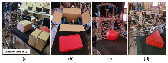
Figure 13.
(a) Experimental setup for boxes. (b) Boxes and configurations used in tests. (c) Sphere positioned. (d) Triangular prism in front of robot.
The general work flow of the robot during the execution of the experiments can be seen in Figure 14. Experiments performed by humanoid robot are shown at https://www.youtube.com/watch?v=pfOybpE-T-U (accessed on 26 July 2024).
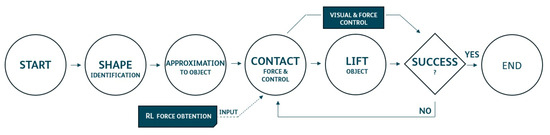
Figure 14.
Experimental work flow.
6.1. Experiment 01: Boxes Lifted Learning by Repetition (Parallel Contact)
The lifting task is carried out in four steps, which are repeated in a loop until the robot autonomously detects that the box has been lifted, as shown in Figure 15. In the first step, TEO performs a safe approach task, maintaining a safe distance from the object. Then, in the second step, the end-effectors position themselves closer to the box, aligning for contact. In the third step, the robot moves its arms until the force sensors detect contact and the necessary pressure on the surface of the box is applied. Finally, in the last step, the robot proceeds to lift its arms.
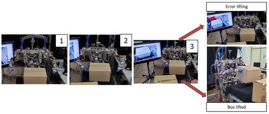
Figure 15.
Program steps 1 to 3 to lift the object and results of the previous steps. Robot lifting the box.
If the arms reach the desired height but the vision algorithm detects that the box has not been lifted, the four steps are cycled, increasing the applied force on each iteration until the box is lifted.
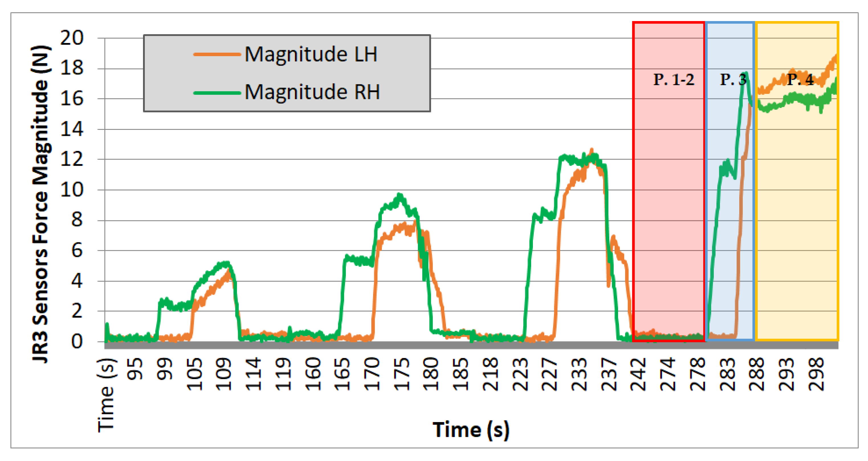
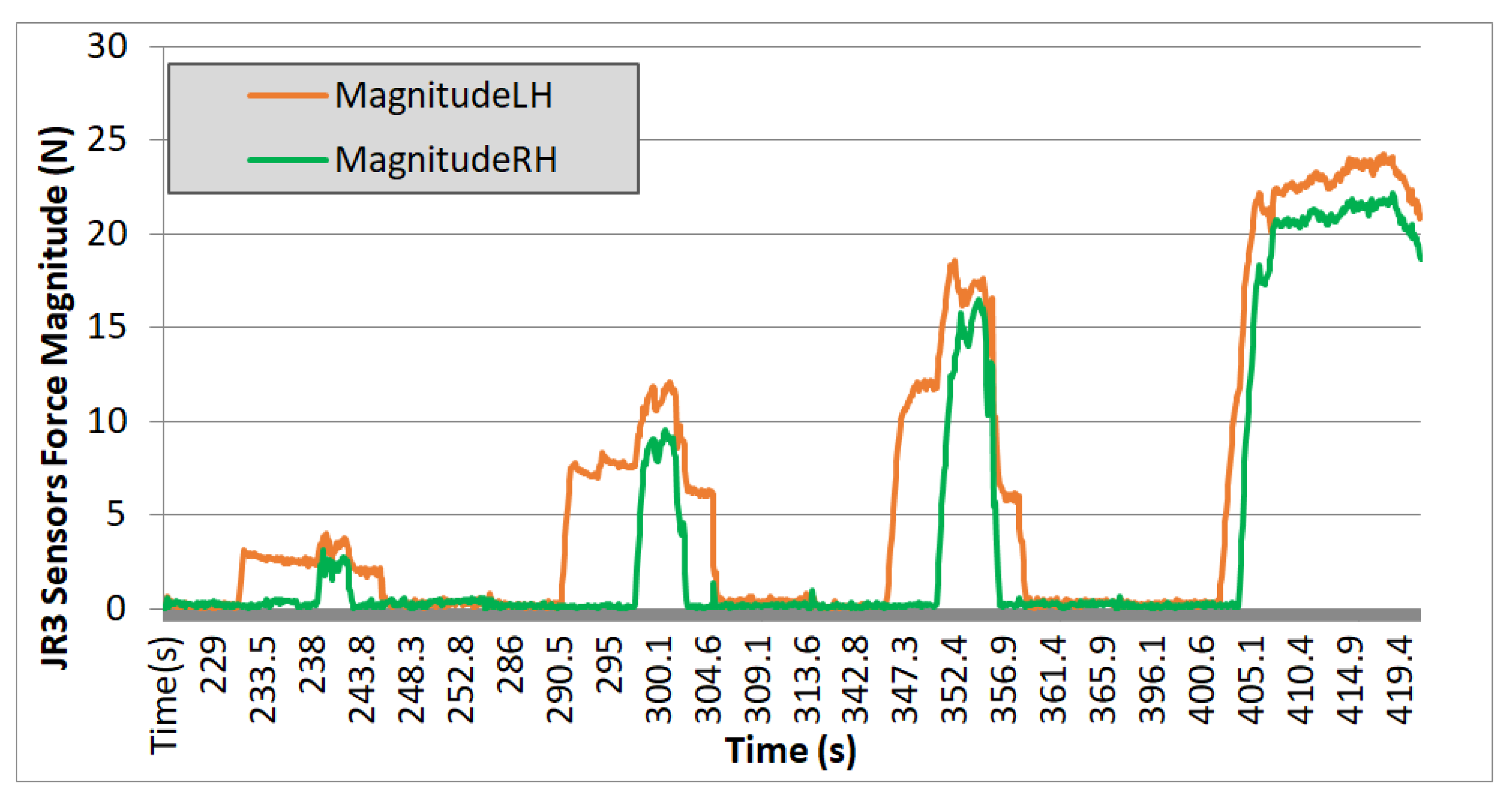
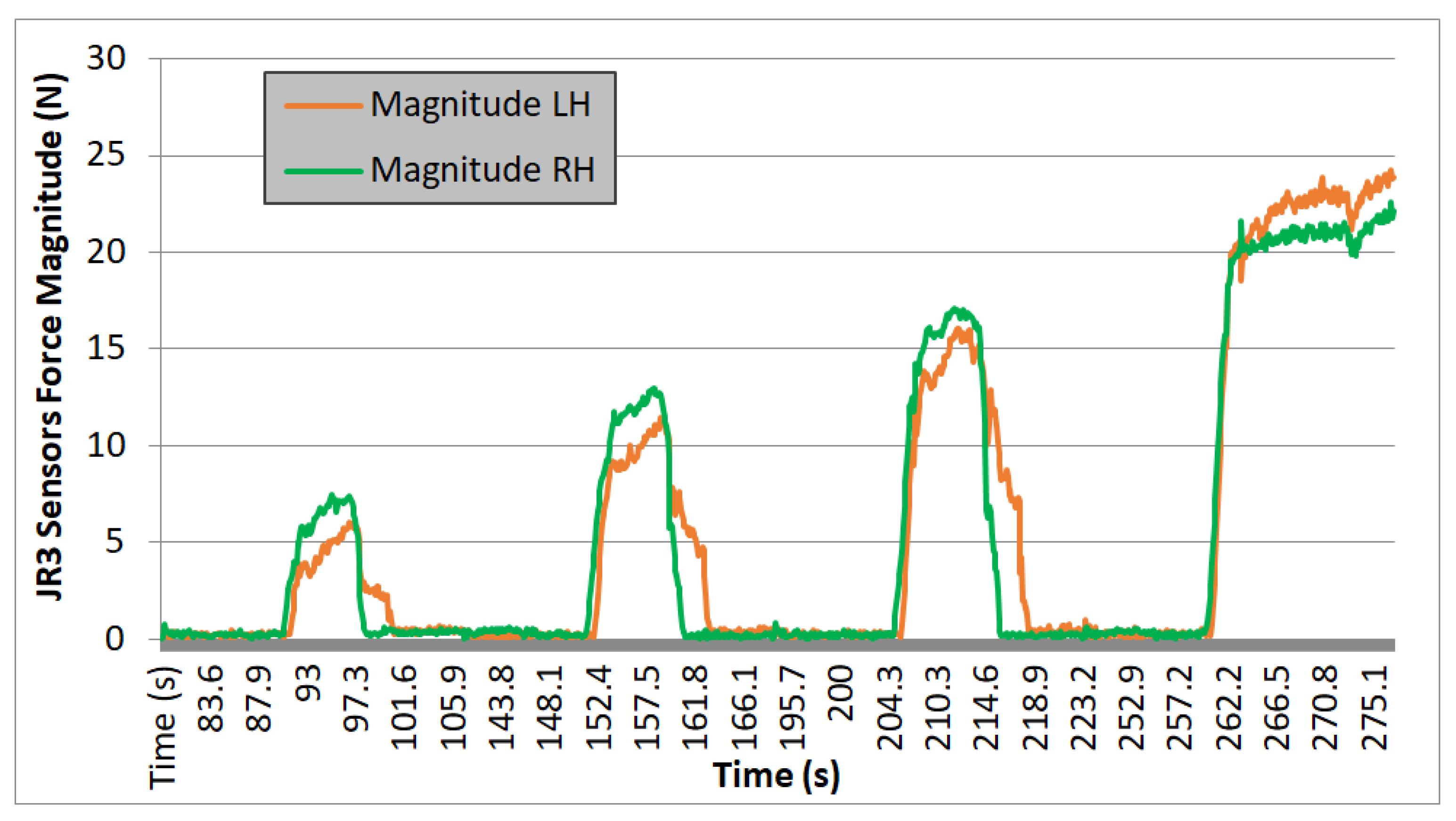
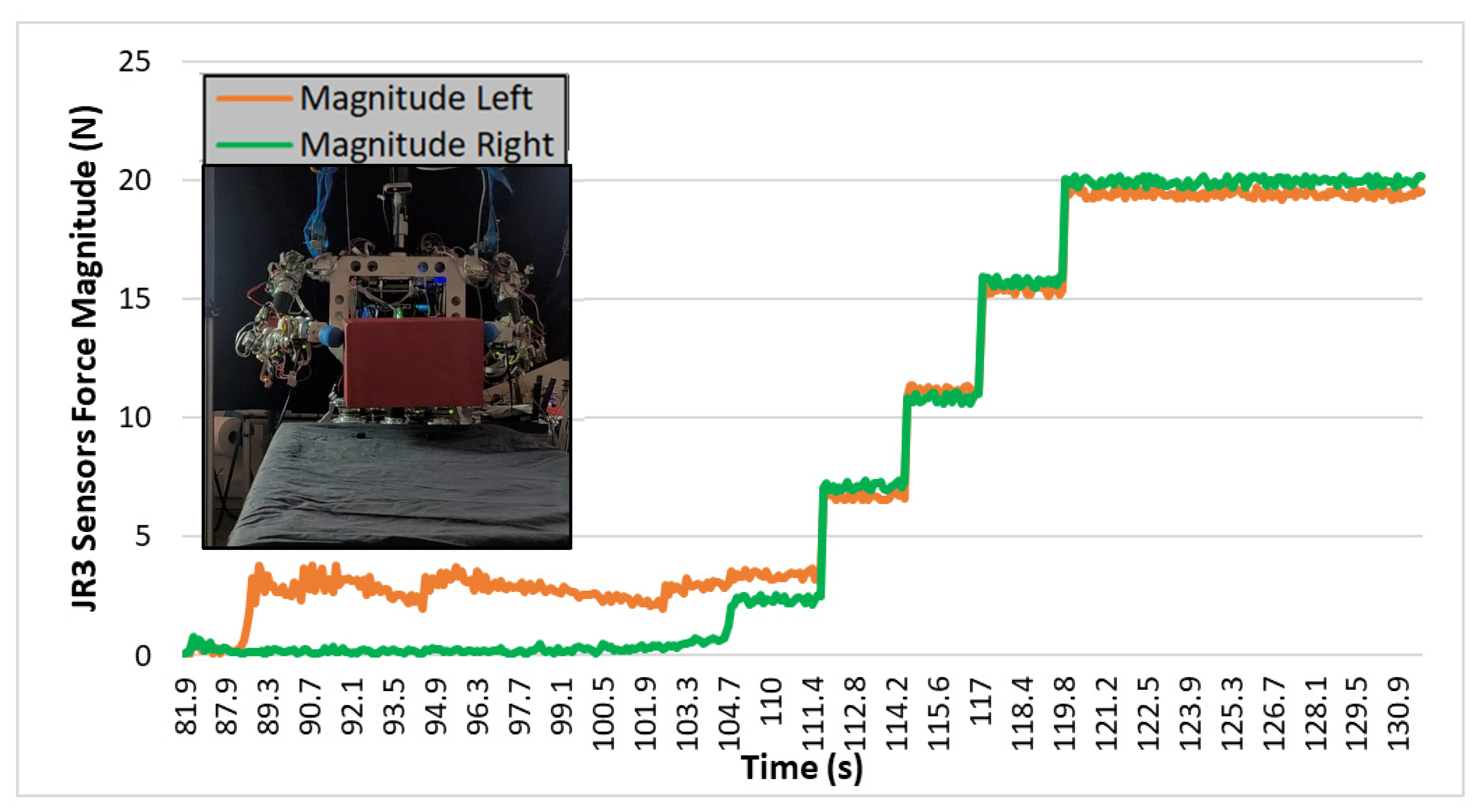
In the experiments carried out with TEO, data were collected on the module of the left arm (LH) and right arm (RH) for all three axes of forces over time, as read by the force sensor. Results are shown in Figure 16, Figure 17 and Figure 18.
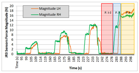
Figure 16.
Test 01. Cardboard box 1.35 kg.
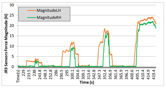
Figure 17.
Test 02. Wooden box 2 kg.
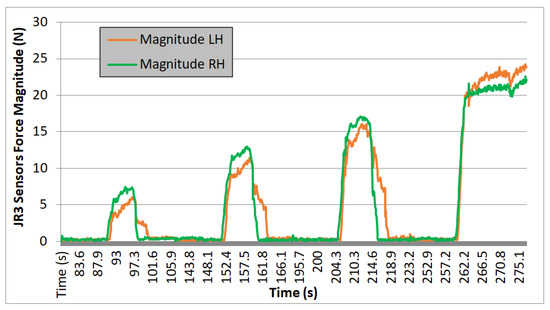
Figure 18.
Test 03. Cardboard box 2.35 kg.
Evaluating the plotted results from the three experiments, the following observations can be made: the system’s behavior is repetitive, and it can be seen that the applied force progressively increases, with four iterations performed in each case. On each iteration, a region with zero force is observed, corresponding to phases 1 and 2 of the movement. During these steps, the force is null because it corresponds to the approach trajectories without contact. Phase 3 begins when the right arm makes contact with the box, increasing the “magnitude RH” value, and ends when the curve reaches a nearly stabilized point. Finally, phase 4 corresponds to the region of the graph where an almost constant force value is observed. It ends either when the force value returns to zero (indicating that the box could not be lifted, and it slipped between the end-effectors) or, in the case of the fourth iteration, when this value remains stable at that force level (indicating that the box is being successfully lifted).
6.2. Experiment 02: Boxes and Sphere Lifted by Real-Life Visual Feedback (Parallel Contact)
Despite the robot achieving the action of lifting different boxes successfully, in terms of energy and time, this way was not optimal. Therefore, the application was improved, and instead of using visual feedback at the end of the movement, the visual information was continuously read, indicating to the robot whether the object was lifted or not. In that way, the robot increased the height of the end-effectors by 2 cm, and if it visually detected that the object did not lift, the force was increased. As can be seen in Figure 19, the robot progressively increased the force until it reached the right force when the object was lifted. In this experiment, the robot found the force to successfully lift the box in 15 s, whereas in previous experiments from Section 6.1, it took about 170 s. There is a reduction of 91.17% of the time needed to perform the task.

Figure 19.
Test 04. Wooden box lifted in one iteration by direct visual feedback.
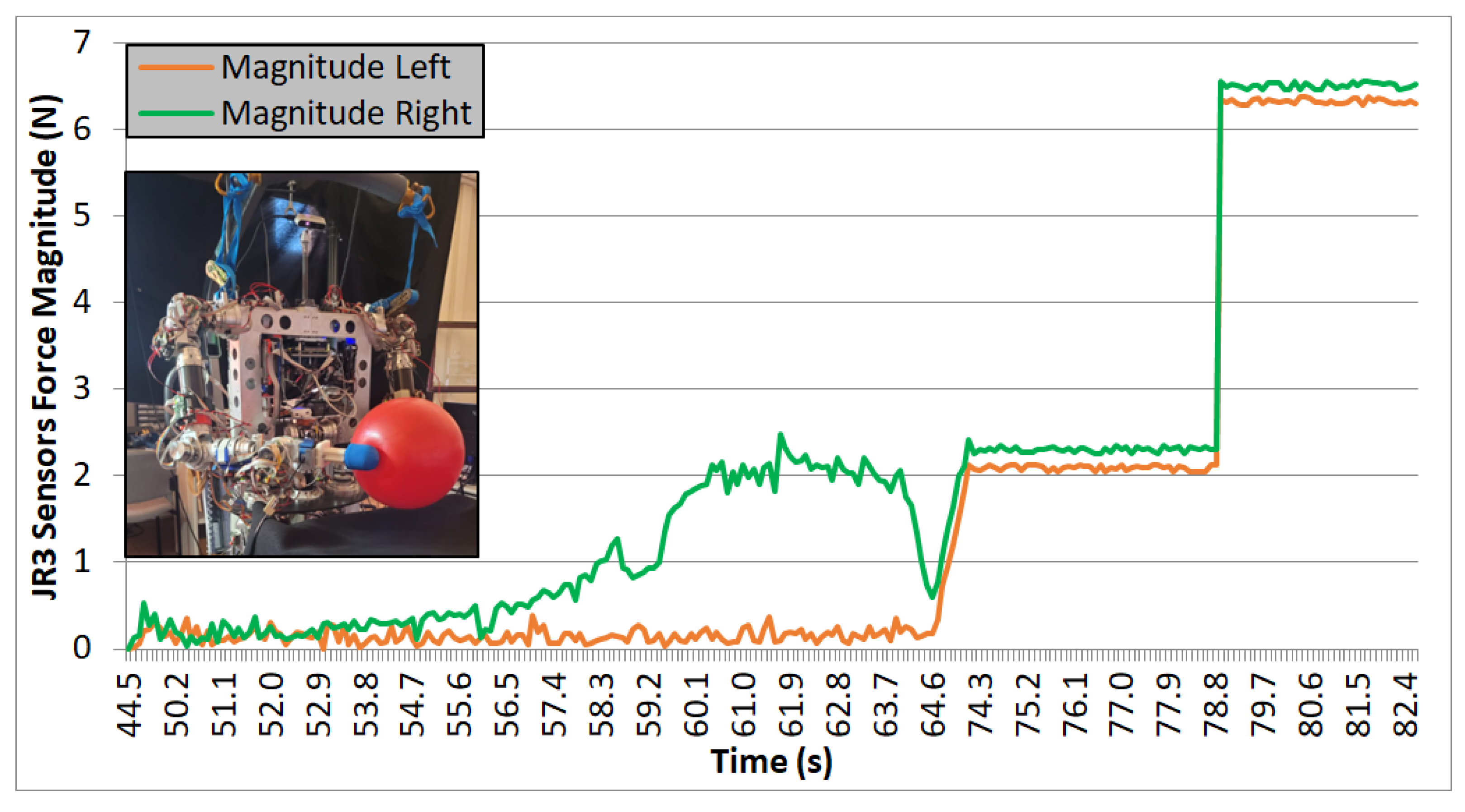
Due to the difference in the weight between the ball (Figure 20) and the box (Figure 19), the force needed by the robot to lift the objects is significantly different, being smaller in the case of the plastic ball. In both cases, the grasping points where the force is applied are on parallel surfaces, and the robot performs the task successfully.

Figure 20.
Test 04. Plastic ball lifted in one iteration by direct visual feedback.
6.3. Experiment 03: Triangular Prism Lifting (Non-Parallel Contact)
As can be seen in Figure 21a,b, firstly, both end-effectors approach to make contact with the surface of the triangular shape represented in red in Figure 21a. These contact points were obtained by the robot using the equations from Section 4.2, according to the positions where force momentums created by both end-effectors are closer to the null value. From that point, the robot tries to apply the force required to perform the lifting task with success. However, as can be seen in Figure 21c, the triangular shape begins to slip. As a consequence, the robot is not capable of exhorting the required force to bi-manipulate the object, and the triangular prism is displaced to a new position (seen in light blue in Figure 21a).
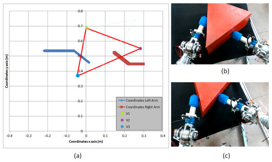
Figure 21.
(a) Trajectory in x and y axis of end-effectors while performing dual-arm task. Initial position of the vertexes (V1-V2-V3) is represented. (b) Initial position of triangular prism. (c) Final position of triangular prism.
7. Reinforcement Learning Algorithm Applied in Non-Parallel Grasping
Due to the absence of parallelism on the surfaces where the end-effectors made the contact within the prism, the robot encountered difficulties in achieving an end-effector position where the force moments were null. Despite the theoretical existence and calculation of nulling points, as highlighted in Section 6.3, the prism exhibited a flipping behavior during experimental execution. This outcome is not unexpected, given that the bi-manipulation strategy employed resulted in an asymmetric grasping configuration, proving challenging for individuals attempting to lift the triangular prism with one finger from each hand while making contact on the surface.
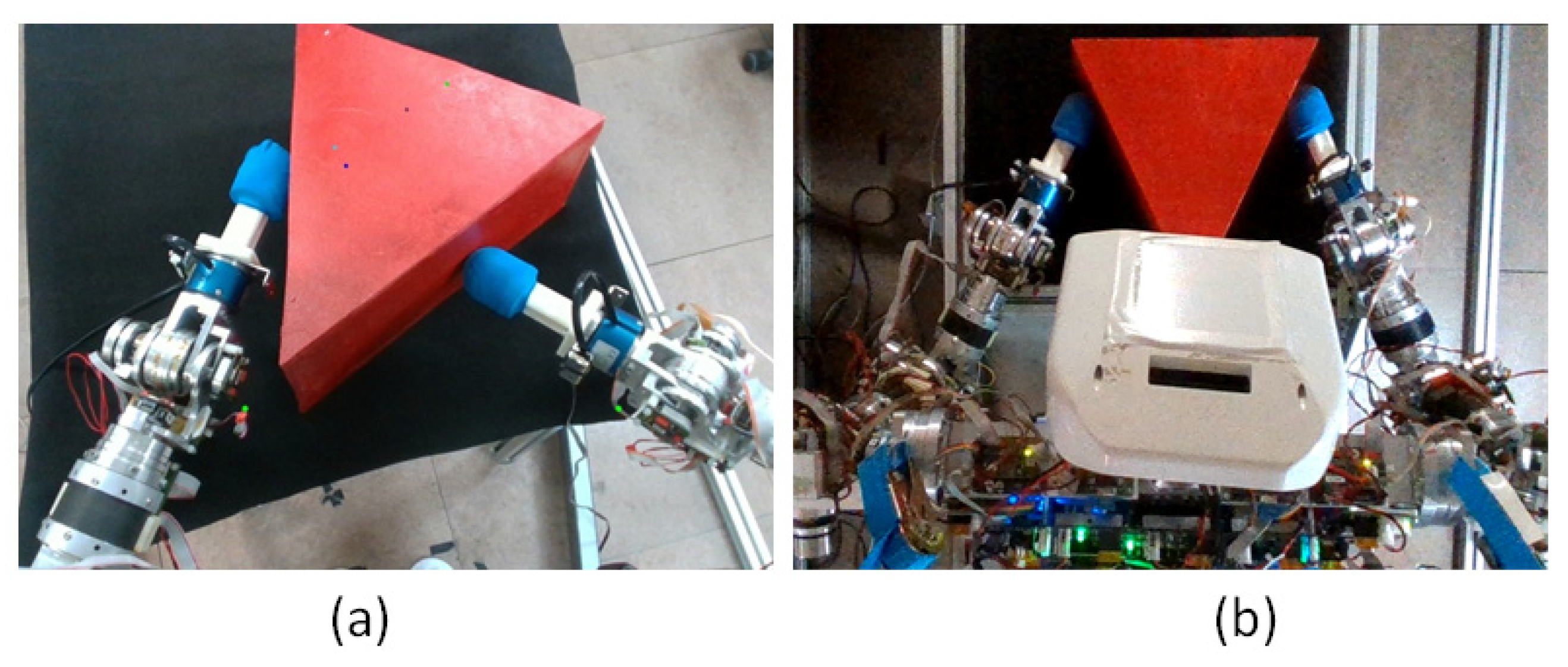
Consequently, a novel manipulation strategy is proposed. Instead of seeking two contact points where the moments are null by traversing the center of the triangular prism, as depicted in Figure 22a, an alternative approach involving symmetrical forces applied to the lateral faces of the prism, as illustrated in Figure 22b, was pursued. In this approach, the robot is tasked with determining a force magnitude sufficient to secure and elevate the triangular prism while maintaining a low level to prevent slippage. To ascertain this specific force value, a reinforcement learning (RL) algorithm was employed. Analogous to the iterative process observed in babies learning to grasp objects through repeated trials and errors, the robot learns the required force for lifting the object by manipulating the non-parallel faces in a similar manner.
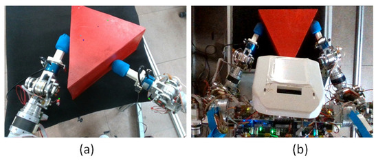
Figure 22.
(a) First approach (trigonometric calculus null momentum). (b) Second approach (RL).
7.1. RL Elements
As seen in [27,28,29], RL algorithms have some elements which must be defined: agent, environment, actions, state, and rewards. In this subsection, those elements as well as the final goal are defined:
- RL Goal: Finding the maximum value of the force (F) that the robot can apply with the end-effectors over the non-parallel faces of the prism without causing the object to slip.
- Agent: The humanoid robot with two arms.
- Environment: The triangular shape, positioned over a table in front of the robot.
- Action: The robot can exert different force values over the lateral surfaces of the triangle. A discrete range of forces that covers from 0 N to 50 N is set. The goal of the algorithm is to find a force value which is inside a range of two force values. Each learning episode of the RL algorithm is composed of two actions: the first action (F1), a force that should not move the object, and the second action (F2), a higher force which should move it.
- State: The response of the triangle after each pair of forces is applied will be recovered in the system state. For that reason, after each episode, three pieces of information are acquired:
- ○
- Result of first force (F1): If the robot has not moved the prism, the value is zero. If the robot has moved it, the value is one.
- ○
- Result of second force (F2): Same values as in previous case.
- ○
- Force difference (DIFF): Difference between both forces.
EpisodeSt = [F1, F2, DIFF]However, this information only depicts the state of a specific episode. The accumulated information from all episodes is stored in a 50 × 50-sized bi-dimensional matrix. This size is according to the discrete values of the range of 50 N which can be made. The x-axis from the matrix shows the first force (F1) applied in each episode and y-axis shows the second force (F2) from those episodes. In that matrix, the rewards and punishments are saved. - Termination condition: The condition that allows the algorithm to finish is finding a force range in the same episode such as that seen in Table 2:
Table 2. Termination condition reward.
- ○
- First force exerted does not move the triangular prism. → F1 = 0
- ○
- Second force applied over the prism moves it. → F2 = 1
- ○
- Difference between second force and first force is maximum 2 Newtons.
- Rewards and punishments: It can happen that in the same episode, the robot applies two forces that do not move the triangular shape. The opposite situation can also occur, where the prism is moved with both forces. Both cases (Table 3) are not useful, as they do not help to find the limit force without slip. As a consequence, when this is the robot’s performance, it receives a punishment of minus five points.
Table 3. Negative reward condition.
When the robot is capable of exerting a first force without moving the triangular prism and a second force moving it in the same episode, it receives a reward of 3 positive points. Furthermore, if in the following episode (ep) it is capable of reducing the force differences, it receives a positive reward of 10 points (Table 4):
Table 4.
Positive reward condition.
7.2. RL Algorithm and Exploit vs. Exploration Policy
Based on the previous information, the quality of the actions performed in each iteration by the robot is evaluated by using the Q learning algorithm. The algorithm’s goal is to learn a policy, or strategy, that maximizes the cumulative reward over time. The equation that defines the Q value update rule is as in (13):
where
Q(s,a)←(1 − α) ⋅ Q(s,a) + α ⋅ (r + γ ⋅ maxaQ(s′,a))
- Q(s,a) is the Q-value for state s and action a.
- α is the learning rate, controlling how much the agent learns in each step.
- r is the reward received after taking action a in state s.
- γ is the discount factor, modeling the relative importance of future rewards.
- s′ is the next state after taking action a.
In RL is important to keep a good balance between exploration and exploitation. Excessive exploration within the algorithm may result in suboptimal performance, while an undue emphasis on exploitation risks forsaking potentially superior solutions, culminating in the convergence to a local optimum. While trying to maximize the learning process there has been stated some constraints to help the algorithm tilting between both options.
As it is expected, in the initial stages when there is lack of information, the algorithm selects actions (forces) randomly. This persists until the algorithm identifies actions that yield positive rewards. From that point, the chances for the algorithm to choose random actions start decaying by following an epsilon-greedy policy as seen in Equation (14):
where the value of epsilon (ε) controls the trade-off between exploration and exploitation. By ensuring a minimum value of 0.01, epsilon does not decay too much and continues having some exploration chances. Also, there is a gradual reduction in epsilon by 0.5% in each iteration, implying a tendency to decrease over time.
7.3. RL Experimental Setup
As can be seen in Figure 22b, prism has been set in front of the robot over a table, symmetrically oriented. The robot first reaches a safety position. Then, it moves the end-effectors until it applies a force previously obtained by the algorithm, based on its experience or a random choice. Thirdly, it is identified whether the triangular prism was moved or not. Afterwards, the robot goes again to the safety position, and in case the object was moved, it waits until it is relocated to start the new iteration. This loop is repeated during all the experiment until the robot compiles enough information to find the solution.
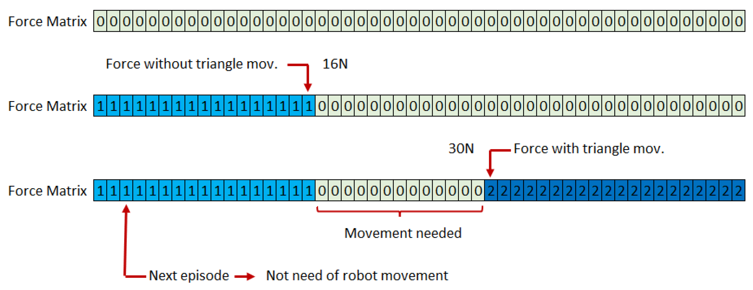
During the experiment, to speed up the learning process, robot movements were minimized by creating a “Force Matrix”, as seen in Figure 23. It is composed of 50 cells (1 for each applicable Newton force). Before the robot performs any movement, all the values are zero. When a force has been applied, and the prism has not been moved, all the forces below that value are set to 1. However, if the force applied moves the triangular prism, all the values over the position of that cell are set to 2. In that way, in each episode, the robot only performs the movement if the value of the array for that force is zero. Otherwise, it takes the necessary information to feed the Q-learning algorithm from the “Force Matrix”. This strategy has helped to accelerate the trial-and-error learning process.
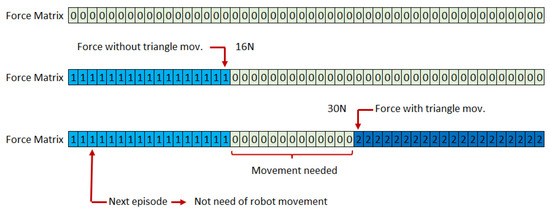
Figure 23.
Force matrix. Record of the real robot movements results after force application.
7.4. RL Experimental Results
The experiment was repeated 10 times, allowing the robot to perform a maximum of 200 iterations per experiment. In all the cases, the algorithm has converged to the solution before performing 50 iterations. Considering that exists 2500 force combinations, and half of them are symmetrical results, it exists 1250 force combinations. The system needs to explore a maximum of 4% of the combinations to guess the maximum force that allows the dual-arm manipulation of the triangular prism without slip. In all cases, the algorithm has come to the solution between 33 and 35 N of the grasping force limit.
Table 5 shows the iterations from one experiment until it comes to the solution of 33 N.
Table 5.
Reinforcement learning results after application.
In Table 5, it can be seen that the algorithm combines both exploration and exploitation decisions, and it converges to the solution to finally find the limit force that can be applied over the triangular prism without slip. As can be seen, positive rewards have a reduction factor directly related to the number of episodes needed by the algorithm to find the solution, thereby encouraging the algorithm to find the solution in the shortest possible term.
7.5. Lifting Force Validation
The force obtained through the reinforcement learning algorithm allows us to determine the maximum force that we can apply while lifting avoiding any slippery. This information was used to feed the dual-arm manipulation loop to perform the lifting action.
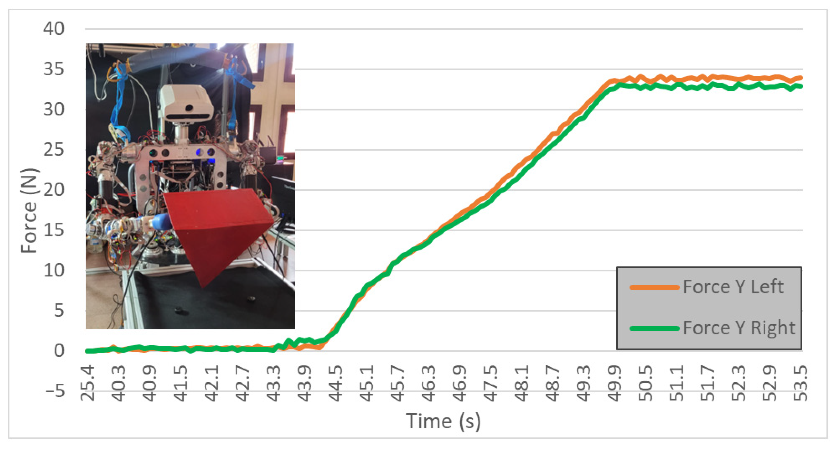
Firstly, the robot has segmented the triangular prism from the image and obtained its position and orientation. From that point, the trajectory to reach the contact points of the end-effectors was calculated. Then, the robot has moved the arms, applying the force obtained with the RL algorithm. Finally, the prism was lifted by the robot, by controlling that force. In Figure 24, the steps previously enumerated can be seen: reaching the robot with 33 N in each arm and maintaining it while lifting the object.

Figure 24.
Applying force obtained by RL for the triangular prism lifting action.
8. Conclusions
A fully autonomous system has been successfully developed, capable of identifying different types of shapes (boxes, spheres, triangular prisms) through the processing of information using artificial vision techniques. Moreover, the experiments were conducted simulating a human-like environment, where there may be disorder and changes.
By fusing force, position, and vision sensors, a closed-loop controller has been implemented, granting the robot the ability to iteratively self-regulate its force to perform the task. To validate this adaptive capacity, tests have been conducted with various boxes of different weights, varying the content inside them. Firstly, it gives visual feedback after the end of each movement. Then, it reads visual information in life and adapts the grasping force to lift the object in one iteration.
Without receiving any input from humans, TEO autonomously obtained the position of the object, generated the trajectory, and adjusted the force to carry out the tasks of lifting the boxes and the sphere, achieving autonomous dual-arm manipulation in objects with parallel surfaces.
On the other hand, two different approaches were tried by the robot to lift an object, applying the contact points on surfaces which are not parallel. The first one, based on the geometrical shape of the object, was not successful due to the inherent difficulty that is already present for humans and the need for high accuracy to null the momentums. This approach also had the disadvantage of being limited to triangular shapes. The second approach was performed by using RL techniques. In that case, the maximum force allowing the object to be lifted without a slippery effect was found. Then, the triangular prism was lifted. The advantage of using the second approach is that this RL algorithm could be used to find the limit force to grasp without slip on any shape with non-parallel faces. As future work, this algorithm could be checked with other different objects.
As future work, the integration of the system to make it adaptable to other robots is underway, and there are planned to replicate these same tests with a completely different robot.
This research introduces three main innovations: the autonomous capability of the robot to adapt the bi-manipulation to various objects positioned and oriented differently, utilizing online visual, force, and position feedback. This enables the robot to autonomously determine whether it is correctly performing the task of lifting an object. Geometric shapes such as cubes and spheres were chosen for parallel gripping, with the idea that future work can leverage other research on the bi-manipulation of objects approximating simpler shapes. Finally, a reinforcement learning methodology was developed to enable the robot to lift objects that do not have symmetrical faces for gripping.
Author Contributions
Conceptualization, J.H.-V. and S.M.; methodology, J.H.-V. and S.M.; software, J.H.-V. and B.Ł.; validation, J.H.-V.; formal analysis, J.H.-V. and S.M.; investigation, J.H.-V.; resources, N.T. and C.B.; data curation, J.H.-V.; writing—original draft preparation, J.H.-V.; writing—review and editing, J.H.-V. and S.M.; visualization, J.H.-V.; supervision, S.M., N.T. and C.B.; funding acquisition, N.T. and C.B. All authors have read and agreed to the published version of the manuscript.
Funding
The research leading to these results has received funding from the COMPANION-CM project: Artificial intelligence and cognitive models for symmetric human-robot interaction in the field of assistive robotics, reference Y2020/NMT-6660, funded by Proyectos Sinérgicos de I+D la Comunidad de Madrid.
Data Availability Statement
Data are contained within the article. A video will be uploaded to the platform.
Acknowledgments
Thanks to all the team in IIT for allowing me to spend 4 months in the robotics laboratory and to be able to work with CENTAURO.
Conflicts of Interest
The authors declare no conflicts of interest.
References
- Karar, A.S.; Said, S.; Beyrouthy, T. Pepper humanoid robot as a service robot: A customer approach. In Proceedings of the 2019 3rd International Conference on Bio-Engineering for Smart Technologies (BioSMART), Paris, France, 24–26 April 2019; IEEE: Piscataway, NJ, USA, 2019; pp. 1–4. [Google Scholar]
- Attamimi, M.; Araki, T.; Nakamura, T.; Nagai, T. Visual recognition system for cleaning tasks by humanoid robots. Int. J. Adv. Robot. Syst. 2013, 10, 384. [Google Scholar] [CrossRef]
- Garcia-Haro, J.M.; Oña, E.D.; Hernandez-Vicen, J.; Martinez, S.; Balaguer, C. Service robots in catering applications: A review and future challenges. Electronics 2021, 10, 47. [Google Scholar] [CrossRef]
- He, W.; Li, Z.; Chen, C.P. A survey of human-centered intelligent robots: Issues and challenges. IEEE/CAA J. Autom. Sin. 2017, 4, 602–609. [Google Scholar] [CrossRef]
- Soroka, A.J.; Qiu, R.; Noyvirt, A.; Ji, Z. Challenges for service robots operating in non-industrial environments. In Proceedings of the IEEE 10th International Conference on Industrial Informatics, Beijing, China, 25–27 July 2012; IEEE: Piscataway, NJ, USA, 2012; pp. 1152–1157. [Google Scholar]
- Kimura, N.; Ito, K.; Fuji, T.; Fujimoto, K.; Esaki, K.; Beniyama, F.; Moriya, T. Mobile dual-arm robot for automated order picking system in warehouse containing various kinds of products. In Proceedings of the 2015 IEEE/SICE International Symposium on System Integration (SII), Nagoya, Japan, 11–13 December 2015; IEEE: Piscataway, NJ, USA, 2015; pp. 332–338. [Google Scholar]
- Yan, L.; Mu, Z.; Xu, W.; Yang, B. Coordinated compliance control of dual-arm robot for payload manipulation: Master-slave and shared force control. In Proceedings of the 2016 IEEE/RSJ International Conference on Intelligent Robots and Systems (IROS), Daejeon, Korea, 9–14 October 2016; IEEE: Piscataway, NJ, USA, 2016; pp. 2697–2702. [Google Scholar]
- Caccavale, F.; Chiacchio, P.; Marino, A.; Villani, L. Six-dof impedance control of dual-arm cooperative manipulators. IEEE/ASME Trans. Mechatron. 2008, 13, 576–586. [Google Scholar] [CrossRef]
- Benali, K.; Brethé, J.F.; Guérin, F.; Gorka, M. Dual arm robot manipulator for grasping boxes of different dimensions in a logistics warehouse. In Proceedings of the 2018 IEEE International Conference on Industrial Technology (ICIT), Lyon, France, 19–22 February 2018; IEEE: Piscataway, NJ, USA, 2018; pp. 147–152. [Google Scholar]
- Liu, J.F.; Abdel-Malek, K. Robust control of planar dual-arm cooperative manipulators. Robot. Comput. -Integr. Manuf. 2000, 16, 109–119. [Google Scholar] [CrossRef]
- Turella, L.; Lingnau, A. Neural correlates of grasping. Front. Hum. Neurosci. 2014, 8, 686. [Google Scholar] [CrossRef] [PubMed]
- Jeannerod, M. Specialized channels for cognitive responses. Cognition 1981, 10, 135–137. [Google Scholar] [CrossRef] [PubMed]
- Hernandez-Vicen, J.; Martinez, S.; Balaguer, C. Principios básicos para el desarrollo de una aplicación de bi-manipulación de cajas por un robot humanoide. Rev. Iberoam. Automática Informática Ind. 2021, 18, 129–137. [Google Scholar] [CrossRef]
- Miller, A.T.; Knoop, S.; Christensen, H.I.; Allen, P.K. Automatic grasp planning using shape primitives. In Proceedings of the 2003 IEEE International Conference on Robotics and Automation (Cat. No. 03CH37422), Taipei, Taiwan, 14–19 September 2003; IEEE: Piscataway, NJ, USA, 2003; Volume 2, pp. 1824–1829. [Google Scholar]
- Huebner, K.; Ruthotto, S.; Kragic, D. Minimum volume bounding box decomposition for shape approximation in robot grasping. In Proceedings of the 2008 IEEE International Conference on Robotics and Automation, Shanghai, China, 9–13 May 2008; IEEE: Piscataway, NJ, USA; pp. 1628–1633. [Google Scholar]
- Huebner, K.; Kragic, D. Selection of robot pre-grasps using box-based shape approximation. In Proceedings of the 2008 IEEE/RSJ International Conference on Intelligent Robots and Systems, Nice, France, 22–26 September 2008; IEEE: Piscataway, NJ, USA; pp. 1765–1770. [Google Scholar]
- Smith, C.; Karayiannidis, Y.; Nalpantidis, L.; Gratal, X.; Qi, P.; Dimarogonas, D.V.; Kragic, D. Dual arm manipulation—A survey. Robot. Auton. Syst. 2012, 60, 1340–1353. [Google Scholar] [CrossRef]
- Johansson, R.S.; Westling, G. Roles of glabrous skin receptors and sensorimotor memory in automatic control of precision grip when lifting rougher or more slippery objects. Exp. Brain Res. 1984, 56, 550–564. [Google Scholar] [CrossRef] [PubMed]
- Johansson, R.S.; Flanagan, J.R. Coding and use of tactile signals from the fingertips in object manipulation tasks. Nat. Rev. Neurosci. 2009, 10, 345–359. [Google Scholar] [CrossRef] [PubMed]
- Hernandez-Vicen, J.; Martinez, S.; de Santos-Rico, R.; Menendez, E.; Balaguer, C. Characterization and Study of the Primitive Dynamic Movements Required to Bi-Manipulate a Box. Electronics 2021, 10, 1354. [Google Scholar] [CrossRef]
- Surdilovic, D.; Yakut, Y.; Nguyen, T.M.; Pham, X.B.; Vick, A.; Martin-Martin, R. Compliance control with dual-arm humanoid robots: Design, planning and programming. In Proceedings of the 2010 10th IEEE-RAS International Conference on Humanoid Robots, Nashville, TN, USA, 6–8 December 2010; IEEE: Piscataway, NJ, USA, 2010; pp. 275–281. [Google Scholar]
- Prattichizzo, D.; Trinkle, J.; Siciliano, B.; Khatib, O. Springer Handbook of Robotics; Prattichizzo, D., Trinkle, J.C., Siciliano, B., Eds.; Springer: Berlin, Germany, 2008; Chapter 28. [Google Scholar]
- Chinellato, E. Robust Strategies for Selecting Vision-Based Planar Grasps of Unknown Objects with a Three-Finger Hand; Springer: Berlin, Germany, 2002. [Google Scholar]
- Suárez Feijóo, R.; Cornellà Medrano, J.; Roa Garzón, M. Grasp Quality Measures; Springer: Berlin, Germany, 2006. [Google Scholar]
- Lin, Y.; Sun, Y. Robot grasp planning based on demonstrated grasp strategies. Int. J. Robot. Res. 2015, 34, 26–42. [Google Scholar] [CrossRef]
- Honjo, R.; Katsura, S. Calculation of grasping force to adapt mass variation of object considering human motion. In Proceedings of the IECON 2015-41st Annual Conference of the IEEE Industrial Electronics Society, Yokohama, Japan, 9–12 November 2015; IEEE: Piscataway, NJ, USA, 2015; pp. 004923–004928. [Google Scholar]
- Thrun, S.; Littman, M.L. Reinforcement learning: An introduction. AI Mag. 2000, 21, 103. [Google Scholar]
- Kaelbling, L.P.; Littman, M.L.; Moore, A.W. Reinforcement learning: A survey. J. Artif. Intell. Res. 1996, 4, 237–285. [Google Scholar] [CrossRef]
- Sutton, R.S.; Barto, A.G. Reinforcement Learning: An Introduction; MIT Press: Cambridge, MA, USA, 2018. [Google Scholar]


Disclaimer/Publisher’s Note: The statements, opinions and data contained in all publications are solely those of the individual author(s) and contributor(s) and not of MDPI and/or the editor(s). MDPI and/or the editor(s) disclaim responsibility for any injury to people or property resulting from any ideas, methods, instructions or products referred to in the content. |
© 2024 by the authors. Licensee MDPI, Basel, Switzerland. This article is an open access article distributed under the terms and conditions of the Creative Commons Attribution (CC BY) license (https://creativecommons.org/licenses/by/4.0/).