Article

Post-Earthquake Recovery Phase Monitoring and Mapping Based on UAS Data

by
Nikolaos Soulakellis
1,
Christos Vasilakos
1,*,
Stamatis Chatzistamatis
2,
Dimitris Kavroudakis
1,
Georgios Tataris
1,
Ermioni-Eirini Papadopoulou
1,
Apostolos Papakonstantinou
1,
Olga Roussou
1 and
Themistoklis Kontos
3
1
Department of Geography, University of the Aegean, 81100 Mytilene, Greece
2
Department of Cultural Technology and Communication, University of the Aegean, 81100 Mytilene, Greece
3
Department of Environmental Studies, University of the Aegean, 81100 Mytilene, Greece
*
Author to whom correspondence should be addressed.
ISPRS Int. J. Geo-Inf. 2020, 9(7), 447; https://doi.org/10.3390/ijgi9070447
Submission received: 15 June 2020 / Revised: 10 July 2020 / Accepted: 15 July 2020 / Published: 17 July 2020
(This article belongs to the Special Issue Geomatics and Geo-Information in Earthquake Studies)

Abstract

:
Geoinformatics plays an essential role during the recovery phase of a post-earthquake situation. The aim of this paper is to present the methodology followed and the results obtained by the utilization of Unmanned Aircraft Systems (UASs) 4K-video footage processing and the automation of geo-information methods targeted at both monitoring the demolition process and mapping the demolished buildings. The field campaigns took place on the traditional settlement of Vrisa (Lesvos, Greece), which was heavily damaged by a strong earthquake (Mw=6.3) on June 12th, 2017. For this purpose, a flight campaign took place on 3rd February 2019 for collecting aerial 4K video footage using an Unmanned Aircraft. The Structure from Motion (SfM) method was applied on frames which derived from the 4K video footage, for producing accurate and very detailed 3D point clouds, as well as the Digital Surface Model (DSM) of the building stock of the Vrisa traditional settlement, twenty months after the earthquake. This dataset has been compared with the corresponding one which derived from 25th July 2017, a few days after the earthquake. Two algorithms have been developed for detecting the demolished buildings of the affected area, based on the DSMs and 3D point clouds, correspondingly. The results obtained have been tested through field studies and demonstrate that this methodology is feasible and effective in building demolition detection, giving very accurate results (97%) and, in parallel, is easily applicable and suit well for rapid demolition mapping during the recovery phase of a post-earthquake scenario. The significant advantage of the proposed methodology is its ability to provide reliable results in a very low cost and time-efficient way and to serve all stakeholders and national and local organizations that are responsible for post-earthquake management.

1. Introduction

An earthquake is a rare event that can have a significant impact on humans and the landscape, while it can also affect the socio-economic development of a region [1]. The process of disaster management can affect the severity of the disaster and the duration of the aftermath. Disaster management consists of four phases: mitigation, preparedness, response, and recovery [2]. The recovery phase aims to restore the life of the city, at the pre-destructive levels, as well as to reduce vulnerability in the future [3] and it has a variable time range according to the length of the short-term and long-term phases. The flow of the reconstruction phase depends on the characterization of the disaster-stricken areas by decision-makers, mainly into three types: collective relocation area, rebuilding on original location area, and non-disaster area [4]. The usefulness of geospatial data and fields for monitoring changes has been proven thoroughly over the last few years. Geospatial data regarding disaster management are capable of contributing to a field of research that manages time, spatial, and descriptive information to such an extent [5]. The issue of scale is critical when discussing geospatial information needs for disaster management issues. While many capabilities in earth observation have been aimed at regional to global consideration, the challenge to the research and applications community is to adapt the techniques and the technology of geospatial analysis for disaster management issues to the local level [6].
Widespread 3D acquisition techniques have highlighted the usefulness of 3D data, as it is challenging to understand spatial information using just 2D datasets, such as, for example, a reconstruction plan [7], especially if the building-height changes over time. The development of new computer vision algorithms dramatically reduces the time needed and improves the degree of automation in generating 3D point clouds using photogrammetry techniques. Structure-from-Motion (SfM) is a computational photogrammetry method where the 3D coordinates of an image point are derived by analyzing two or more photos collected from different positions that have significant overlap with each other [8].
Data acquisition techniques using Unmanned Aircraft Systems (UASs) allow for the production of a complete 3D model with the highest possible resolution, wherein a post-earthquake scenario UASs can document the state of an area, ensuring the safety of all operators [9]. The European Commission already assesses the potential role of UASs in emergency situations and in a rapid response and mapping context as “an alternative and/or complementary source of post-event imagery” [10]. UASs can provide rapid solutions with no infrastructure and they are a complement to larger manned-aircraft photography and photogrammetry [11]. The combination of using UASs with the photogrammetric method of SfM has previously been applied for reconnaissance purposes following the 2009 L’Aquila, Italy earthquake [12,13], the 2016 Kumamoto, Japan earthquake [14], the 2016 Amatrice, Italy earthquake [15], the 2016 Kaikoura, New Zealand earthquake [16], and the 2017 Lesvos, Greece earthquake [17,18,19]. In addition to rapid damage assessment, UAS has been used for other disasters related to earthquakes and geological structure (e.g., landslides [20,21,22] and for damage assessment in other type of disasters, such as floods [23]).
One crucial parameter in disaster management is the need for comprehensive imagery acquisition of an area to support monitoring rather than focusing only on specific structures [24]. The approach used to monitor and detect changes in residential areas during the relief phase, where the priority is to identify the most affected areas, differs from that used to detect changes during the recovery phase, where the purpose is to ascertain the progress being made in the recovery process, and also to determine the nature of that progress [25]. Especially during the recovery phase, regular mapping of the urban interface needs to be undertaken using high-resolution geospatial data. The availability of a detailed representation of a disastrous phenomenon, such as an earthquake using UASs, besides the support for the first estimation of occurred damages, can be used for the timely monitoring of the post-disaster situation and recovery process [26]. In [27], the reconstruction process in Bam, Iran after the 2003 earthquake was tracked and analyzed using three approaches to comprehensively assess the reconstruction progress and sustainability of long-term disaster recovery projects.
Change detection (CD) or time-series data analysis in 3D have gained great attention due to their capability of providing volumetric dynamics to facilitate more applications and provide more accurate results. Different methods have their advantages for different types of 3D data, and it is important to select an appropriate approach according to the application and data [28]. More analytically, height differences remain the most straightforward way to compute the geometric differences of two Digital Surface Models (DSMs) in several studies. Menderes et al. [29] and Turker and Cetinkaya [30] revealed the effectiveness of exploiting DSM differences between two epochs in order to detect and map collapsed buildings after a catastrophic earthquake, with an accuracy of 94% and 84%, respectively. Both studies are based only on DSMs and not on 3D point clouds, which is the primary 3D dataset derived from UAS image/video processing. On the other hand, point clouds generated from airborne oblique images have become a suitable source for detailed building damage assessment after a disaster event, since they provide the essential geometric and radiometric features of both roof and façades of the building [31]. The present paper presents the results obtained by processing DSM and 3D Point Clouds individually, in order to better understand the usefulness of 3D point clouds for building demolition mapping of a post-earthquake situation.
The aim of this paper is to present the methodology followed and the results obtained by the exploitation of Unmanned Aircraft Systems (UASs) 4K-video footage processing and the automation of geo-information methods targeted at monitoring the demolition process and mapping the demolished buildings during the recovery phase of a post-earthquake situation. More specifically, this study examines:
  • The usability of UASs 4K video footage in accurately producing 2D and 3D information able to provide urban and rural landscape changes during the recovery phase of a catastrophic earthquake event.
  • The automation of geoinformation processing aiming to detect and map the demolished buildings based on multitemporal 3D information (3D point cloud and DSM).
Even if various studies have been conducted to utilize UASs capabilities for post-earthquake monitoring, to the best of our knowledge, the usability of 3D point clouds has not yet been fully examined, especially for mapping the building demolition process during the recovery phase. Previous studies were mainly focused on using differences of two DSMs, while 3D point clouds were found to be very promising mainly for building damage assessment. Monitoring the recovery process can help the authorities to understand the conditions that may have contributed to the disaster and provide the ability to assist post-earthquake management and reconstruction processes, since such 3D information and geo-visualization can serve all stakeholders and national and local organizations.

2. Materials and Methods

2.1. Study Area and Data Acquisition

On the 12th of June 2017, a magnitude Mw 6.3 earthquake occurred offshore the SE coast of Lesvos island, Greece, as shown in Figure 1 [32,33]. A magnitude Mw 6.3 can be characterized as “a moderate” earthquake, compared to those of other events of the world, such as the 2010 Haiti and 2005 Pakistan earthquakes [34], but it is a serious seismic event for a European country [35]. However, Vrisa village, had un-strengthened masonry buildings and this led to the severe damage of the village. A complete earthquake-induced building damage assessment can be found in [36]. Vrisa was proclaimed by the Greek state as a “traditional settlement” in 2002, because apart from its overall architectural interest it had remarkable architectural and morphological features and was an excellent example of local folk architecture [37].
The geological and geomorphological setting, along with the building characteristics, have been identified as the main factors controlling the spatial distribution of building damages. Specifically, the combination of highly vulnerable old masonry structures founded on alluvial deposits and on slopes in an area bounded by significant faults in combination with probable directivity phenomena resulted in destruction [33]. More analytically, the geology of Lesvos island can be summarized as a basement composed of metamorphic rocks overlain by post-Alpine formations, comprising Miocene volcanic rocks and Neogene marine and lacustrine deposits [38]. As regards the geological setting of the settlement of Vrisa, its western part is founded on Holocene alluvial deposits comprising gray and red clays, sands and gravels, while its eastern part is founded on Pleistocene deposits, including fluvial sand, clays, and conglomerates, with thicknesses of about 100 m [36].
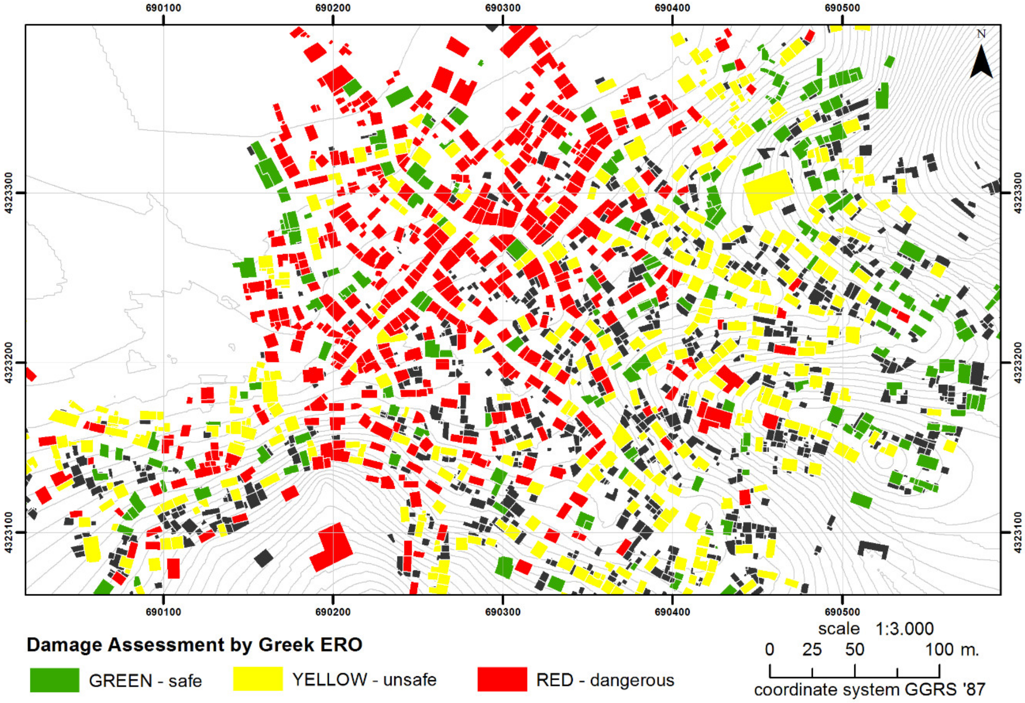
As far as the impact to the built environment of the Vrisa traditional settlement is concerned, shortly after the earthquake, the local Earthquake Rehabilitation Organization (ERO) performed the first and second order visual inspections, where 815 buildings were distinguished into “Green—safe for use”, “Yellow—unsafe for use”, and “Red—dangerous for use”, based on the Earthquake Planning and Protection Organization (EPPO) guidelines [39], and were marked with the appropriate sign based on this damage assessment, as shown in Figure 2. According to the legislation, buildings marked Red should be demolished soon by their owners, while the Yellow and Green ones should be repaired. Practically, several Yellow-marked buildings may also be demolished by their owners, since the cost for their reconstruction is very high. It should be noticed that, according to the legislation and for the purpose of this paper, demolishing a building also includes the transferring of the debris.
After the earthquake, several field campaigns took place for collecting: (a) information concerning the buildings, such as their ERO damage assessment (red, yellow and green), their geographical coordinates, their constructed material (i.e., masonry, R/C building), and number of stores; (b) about 150 ground control points (GCPs) using an RTK system; (c) a UAS (hexacopter) flew over the Vrisa village at 65 m altitude and captured vertical images using a Sony A5100 camera with a fixed lens of 19 mm focal length on 25th July 2017 [17].
In the months after the major earthquake, a number of flights took place in order to capture data for monitoring the recovering process of the village. That is, the demolition activities ask for novel strategies for an automated methodology for multitemporal monitoring and mapping of building-changes, based on UAS video footage. More precisely, the demolition process started, requiring novel strategies for developing a fully automated methodology for the multitemporal monitoring and mapping of the changes occurred, based on UAS video footages. For this purpose, one of the flights took place in February of 2019. The flight mission involved planning and video footage acquisition covering the monitoring area by means of a UAS—Phantom 4 Pro—which is a small and portable quadcopter (weight of around 1.4 kg) and is equipped with a custom 4K video camera that has a 1” CMOS sensor, 84-degree field of view, 24 MP images, and a focal length of 35mm format equivalent. Flight planning is normally performed in the lab with dedicated software (Litchi Hub), starting with the knowledge of the area of interest (AOI), the required ground sample distance (GSD) or footprint, and the intrinsic parameters of the on-board digital camera and the main purpose-goal of the data exploitation. The most crucial flight parameters that are be decided directly affect the quality of the video data and, as such, the quality of the produced 3D point clouds, the digital surface models and the orthophoto maps. More analytically:
  • Flight height: Directly related to the GSD of the video frames. After several flights at different heights, ranging from 30 m to 100 m, it was decided that the height of 80m is the most suitable for the specific study and the GSD was calculated to be approximately 3 cm/pix.
  • Flight speed: Directly affects the video quality as it introduces blurring on the video frames if it is too high and, on the other hand, it requires more time flight and battery energy if it is too slow. After several test flights, it was decided that the most efficient flight speed for acquiring video footage was 25 Km/h.
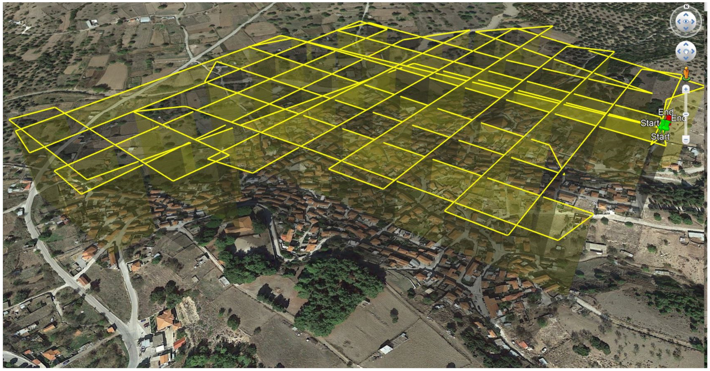
  • Flight path: Directly affects the building appearance in the video footage and controls the side-overlapping of the deriving frames. These two parameters are crucial for the quality and density of the 3D point clouds, especially for points that represent the facades of the buildings. For reaching the specific research goals a flight plan was designed, using Litchi Mission hub software, taking into consideration the shape of the building blocks by following flight paths that are parallel to the streets and with a 50 m distance among them, providing 80% side overlapping, as shown in Figure 3.

2.2. Methodology

The methodology of the present research entails three steps: (i) video footage processing and 3D modeling; (ii) development of the geodatabase of Vrisa buildings; (iii) mapping of demolished buildings by applying two demolition detection algorithms through the exploitation of 3D point clouds and DSMs on different epochs (03/02/2019 and 25/07/2017). The sequence of the methodology is portrayed in Figure 4.

2.2.1. Geo-Registration

Geo-registration is a very crucial step in order to provide absolute orientation and to assign the proper scale to the orthorectified aerial high-resolution images and the 3D point cloud. Thus, it was necessary to add an adequate number of GCPs measured, in the Greek reference system GRS-87, using the RTK technique. The accuracy of the produced orthophoto and DSM, as shown in Table 1 depicts the values of the total RMS error. More specifically, for the geo-registration of the UAS survey 3rd February 2019, 10 GCP’s were used with a total RMS of 2.2 cm. GCP locations and error estimates are depicted in Figure 5, and from the geo-registration accuracy achieved, we can conclude that the precision of the geoinformation produced is of satisfactory accuracy for 3D monitoring and mapping.

2.2.2. Video Footage Processing for 3D Modelling

Video footage processing aims to produce an accurate 3D model of the Vrisa settlement almost 1.5 year after the destructive earthquake. The processing pipeline involves the following steps:
  • Video Frame Extraction—VFE is not a straightforward process since the frames that will be extracted should meet the prerequisites of further processing that leads to generating accurate 3D point clouds and digital surface models. For this reason, the wise frame selection (WFS) approach has been applied, which refers to an elaborated approach that reduces blur-motion effects and frame redundancy, with the aim of discarding the most redundant (i.e., more than 80% front overlap) and lowest-quality frames (i.e., an Image Quality Index (IQI) lower than 0.5 frames).
  • The Structure from Motion (SfM) [40] and Multi View Stereo (MVS) [41] algorithms are the most popular approach in order to create 3D point clouds and digital surface models from a set of 2D images acquired by UAS. This approach has been extensively implemented in the last decade in 3D mapping in different scales and has been employed in some commercial and free software packages in different variations.

2.2.3. Mapping of Demolished Buildings

Mapping of demolished buildings by means of (i) 3D point clouds and (ii) DSM derived by UAS high-resolution images and video footage has been performed using the following two parallel processing steps:
  • Extract the 3D point clouds of each building from the 25th July 2017 and 3rd February 2019 datasets by using the building polygons derived by the photointerpretation of the 25th July 2017 ortho-photomap.
  • Extract the DSM values of each building from the 25th July 2017 and 3rd February 2019 datasets by using the building polygons derived by the photointerpretation of the 25th July 2017 ortho-photomap.
  • Application of the demolition detection algorithms to above datasets for each building and evaluation of the results by field data. More analytically, two demolition detection algorithms have been developed, the first for mapping the demolished buildings by comparing 3D point clouds on different epochs while the second one by comparing the DSMs on different epochs.
The main methodology for building extraction from point clouds is the filtering for the separation of ground from non-ground points followed by a segmentation algorithm for the detection of the building objects [42]. However, in the present monitoring study, building objects are already known and mapped by interpreting the 25/07/2017 orthophoto map, therefore the main task was to identify 3D change detection within these specific building polygons during a time period. One of the applied methodologies was to compare the segmented point clouds in order to identify buildings which were demolished, and their debris was transferred. This comparison was based on point cloud statistics and specifically on their mean height values. Each building was classified as demolished or non-demolished by calculating the difference of the above metrics for the point clouds. These differences were compared with various thresholds (i.e., 0.5 m, 1 m, 1.5 m, 2 m, 2.5 m, 3 m, 3.5 m) to classify them. For each threshold, the classification confusion matrix, the accuracy, the sensitivity, the specificity, and the Cohen’s Kappa [43] were computed.
Additionally, the DSMs were also used for the classification of the demolished buildings based on the two DSM (i.e., T1 (July 2017) and T2 (February 2019)). We used 30 statistical measures for the mathematical difference between the two DSMs in order to feed the algorithm. In other words, for each building polygon we produced 30 numerical measures, most of which were related to the cell by cell differences between the T1 and T2 periods. The spatial multivariate dataset we obtained asks for an efficient approach of identifying the most suitable variable along with its cut-off thresholds in order to classify the building polygons into two classes—1: Demolished; 2: Non-Demolished. There is a need for an unsupervised binary classification method, capable of handling multivariate data.
Recursive partitioning is a well-established classification approach that provides a useful alternative to the parametric methods [44,45,46]. This method does not rely on assumptions, regarding the dependency of the dependent variable, against the predictors. It is a non-parametric method for classification based on tree structures and rules extraction. The results of such a method include rules based on thresholds that need to follow in order to classify a case. The tree structure includes nodes that form mathematical sub-groupings of the learning sample with terminal nodes that cannot be split further. This partitioning method includes a pruning option that identifies a sub-tree of the saturated tree that is most “predictive” of the outcome and least vulnerable to the noise of the multivariable data.

3. Results and Discussion

3.1. Orthophoto Map of 3rd February 2019

The orthophoto map produced by the application of SfM and MVS algorithms comprised 578 frames derived by 4K video footage acquired on 03/02/2019. The total duration of the video footage was ~34 min and 600 frames were extracted (1 frame every 3 s) and finally, 578 frames were selected for processing, fulfilling the requirements for 3D modeling. The map size was 25,556 × 19,160 pixels, having a spatial resolution of 2.98 cm/pix and thus covering an area of 0.281 km2 using coordinate system GGRS87/Greek Grid (EPSG:2100). This map of Vrisa’s traditional village, almost 20 months after the destructive earthquake, at a cartographic scale 1:100, clearly presents the changes that occurred at the village during the recovery phase. A visual interpretation and comparison with the orthophoto map of 25th July 2017 show that: (i) a large number of buildings have been demolished, changing dramatically the image of the village; (ii) debris volumes by collapsed buildings or walls have been removed; (iii) some abandoned damaged buildings further collapsed, as shown in Figure 6.

3.2. 3D Point Cloud of 3rd February 2019

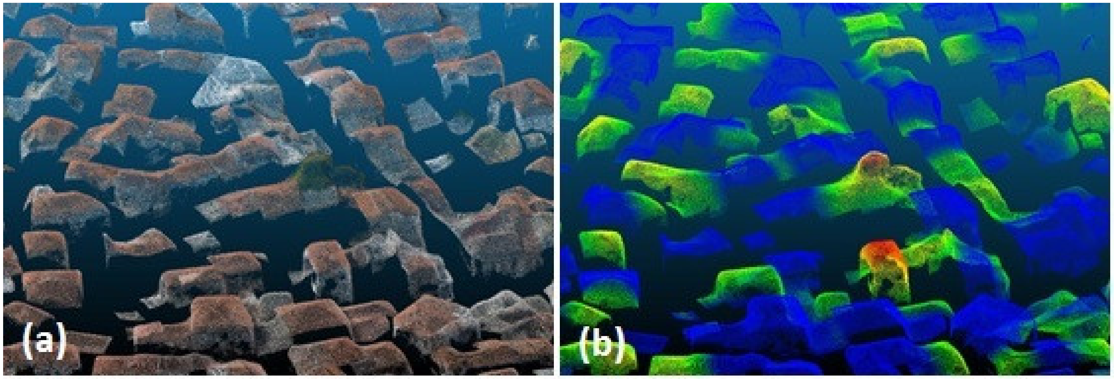
The 3D point cloud of 03/02/2019 consists of 30,840,291 points for the whole study area. A visual interpretation and comparison with the 3D point cloud of 25th July 2017 show that a large number of buildings have been demolished. By visually combining the two points clouds, the damaged buildings’ point clouds of the oldest dataset appear on top of the grounds’ point clouds of the newest one, as shown in Figure 7a,b.
Change detection analysis using UAS data is a demanding process because 3D point clouds produced by applying the SfM algorithm on images acquired on different temporal epochs and/or by different UAS sensors need to be comparable. In 3D change detection, both pre- and post-demolition process point clouds are required, and pair-wise changes emerging from the pre-post comparison are attributed to their demolition. For comparison purposes, ancillary data for the village blocks were used, either already available or easily extracted by manual interpretation of orthophoto maps, to further improve the accuracy of the comparison by discarding unnecessary parts of the scene (roads, ground, trees, etc.). Thus the point clouds were homogenized to avoid “class merging” effects when measuring distances in pre and post building stock condition.
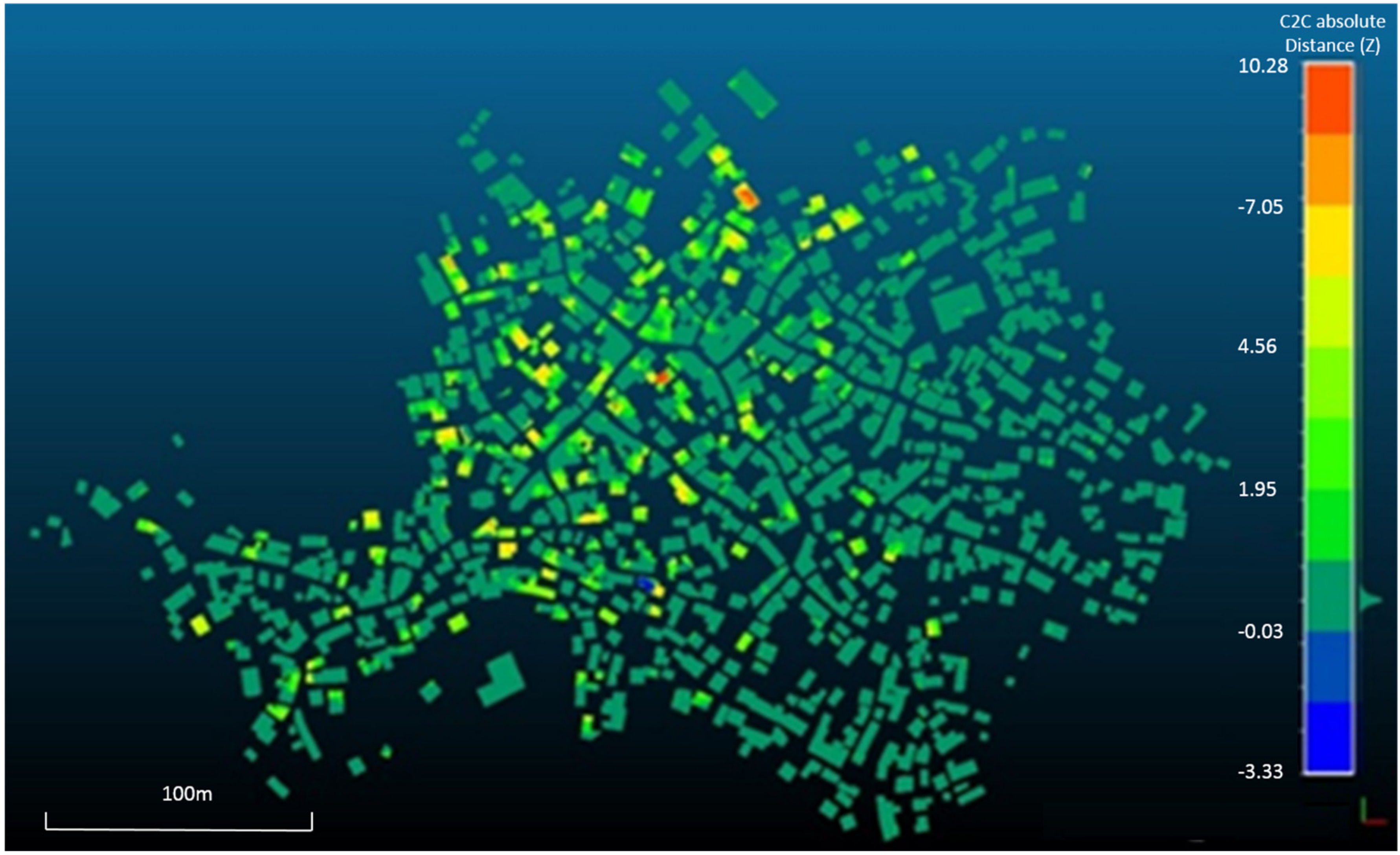
A cloud to cloud comparison was realized to describe the height differences between the buildings that were demolished or collapsed after the first flight due to post-seismic activity. The differences between the two-point clouds are measured using the least-square best fitting plane calculating the nearest point and its neighbors. As a reference cloud, the newest (03/02/2019) point cloud was selected, and the point cloud created from the data acquired on 25/07/2017 was the point cloud on which the distances will be computed. For the cloud to cloud comparison, the open-source program CloudCompare was used to calculate the distances of each point relative to the reference cloud points [47]. The newest point cloud was selected due to the higher point density. The results showed that the height differences between the two-point clouds have a variation between −3.33 and 10.28 m. In Figure 8, the absolute distance in the z-axis for the total area of building stock is illustrated. The means and the standard deviations of the calculated cloud to cloud point distances were 0.57 m and 1.40 m, respectively.
The positive values were validated from a ground-truth campaign depicting, with high accuracy, the demolished building stock and its randomness in building silhouette changes. The negative values, especially the values less than 0.50 m, were miscalculated distances associated with vegetation and shadows. More specific, the highest negative value corresponds to a demolished house that, in the post demolition state, had a tree close by its roof, as shown in Figure 9.
The shadow effect in the area around roofs can produce local extrema to the height differences variation between the two-point clouds. Thus, a confident way to isolate building stock points from all other point classes is critical for the accurate point to point comparison. The small variance in absolute height difference between the two-point clouds leads to the conclusion that different survey flights by means of season and UAS sensors can produce comparable results. Furthermore, the cloud to cloud comparison between two different aerial acquisition datasets can produce robust change detection results in anthropogenic structure damage identification.

3.3. DSM of Difference Map between 3rd February 2019 and 25th July 2017

During the present study, a high resolution (11 cm) DSM has been created, presenting the heights of Vrisa traditional village almost 20 months after the earthquake. By subtracting this DSM from the DSM of 25th July 2017, a DSM of difference map was created, showing the depression of height values (blue colors on map) of the demolished buildings. The DSM of difference map, as shown in Figure 10, has five classes for the negative values of heights, which refers to areas that lost surface height due to the demolition process. More analytically, the map-class from −1.5 m to −6 m corresponds to one-story buildings, while the map-class from −6 m to −9 m refers to two-story buildings, and, finally, the map-class <−9 m refers to three-story buildings.

3.4. Demolition Detection Algorithm with 3D Point Cloud

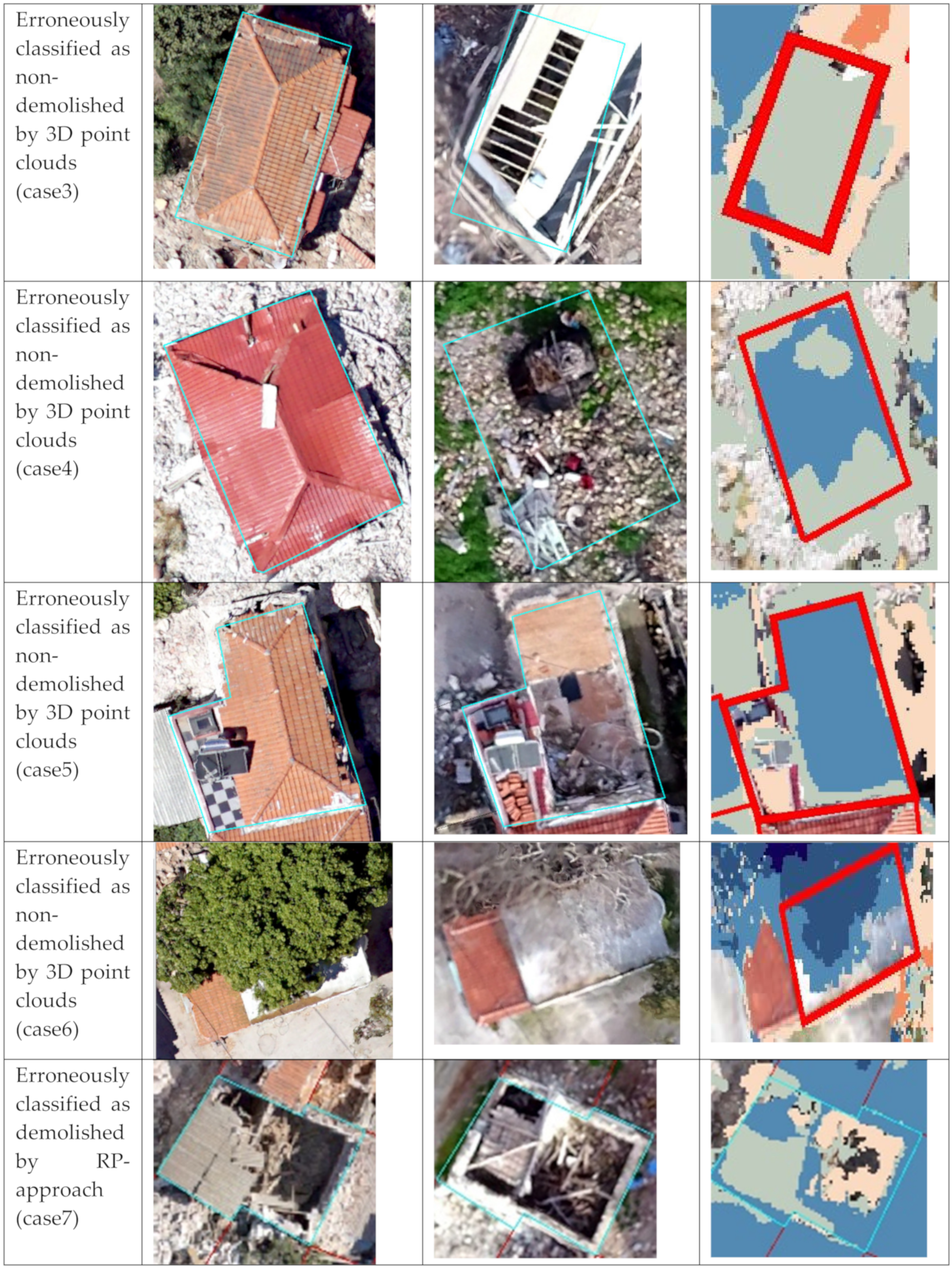
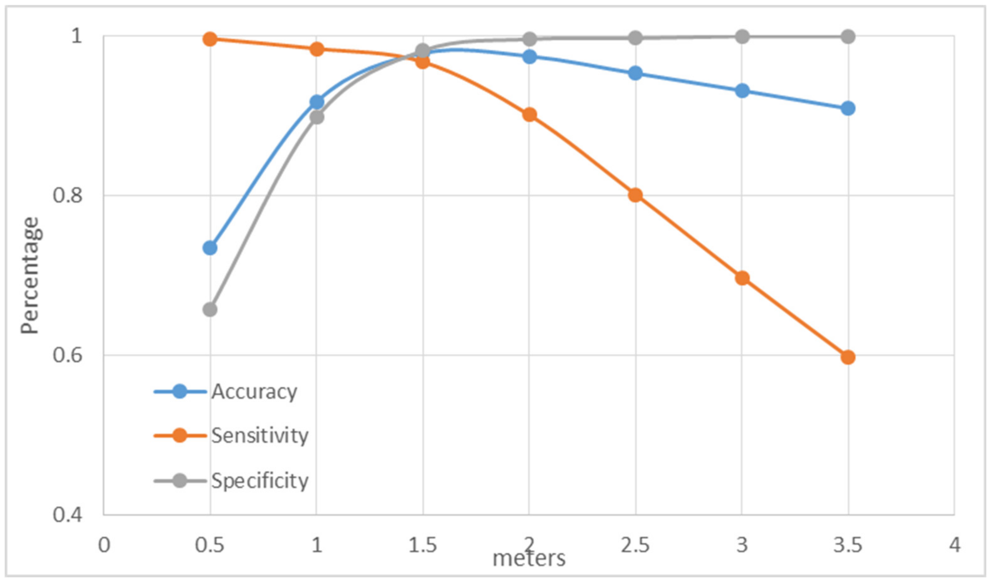
Figure 11 presents the accuracy, sensitivity, and specificity for different thresholds of the difference between the mean heights of the two point clouds. According to the results, the difference of the mean height values between the two point clouds can identify the demolished, as shown in Figure A1—case1, from non-demolished, as shown in Figure A1—case2, buildings with an accuracy of 97.8% when a 1.5 m threshold is applied for these differences, as shown in Table A1. This threshold was chosen because of its better performance in the classification of demolished buildings. However, 24 buildings are misclassified due to various reasons. Eight demolished buildings were classified as non-demolished. One of them was sited in a parcel where a new building was under construction. Therefore, there was no significant difference between the heights, as shown in Figure A1—case3. The rest of the buildings were totally collapsed by the earthquake and the height of the debris was lower than 1.5 m, hence they were misclassified, as shown in Figure A1—case4. On the other hand, 16 not-collapsed buildings were classified as collapsed. Most of them were misclassified due to partial collapse between the two acquisition dates, as shown in Figure A1—case5. Furthermore, some buildings were misclassified because of the different number of points of the clouds between the two dates. In these cases, in epoch T1, only the roof and the facade were visible due to neighborhood buildings. In epoch T2, one or more neighborhood buildings were demolished, and the side walls were then visible, leading to lower mean height values. Finally, a building was misclassified due to a deciduous tree (plane tree) covering the roof during the summer acquisition date, as shown in Figure A1—case6.

3.5. Demolition Detection Algorithm from DSMs

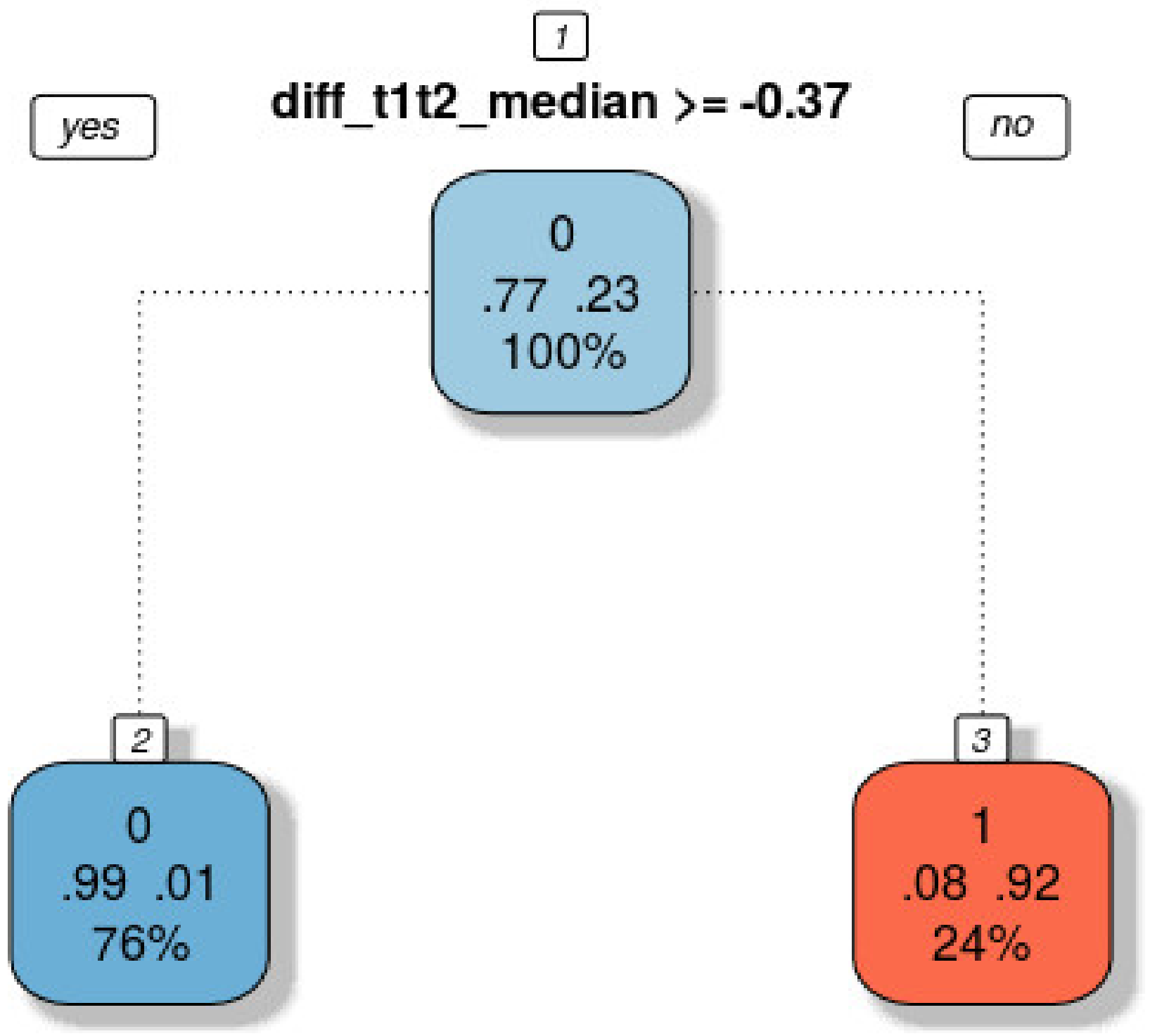
With the use of R programming language [48] and the use of relevant machine learning libraries [44], we conducted recursive partitioning on the multivariate dataset. The result of this approach is a partition tree structure, which is depicted in Figure 12.
According to the resulting tree, the single most important variable for the classification of the multivariate dataset into two classes is the median of the differences between T1 and T2. The threshold for this variable, which is used for the most accurate dichotomy of the multivariate dataset in two classes is −0.37 m. The confusion matrix indicated that most of the building polygons have been classified accurately. More specifically, out of 1079 total cases, 12 buildings have been erroneously classified as demolished by the recursive partitioning approach and two erroneously classified as non-demolished. The overall accuracy of the classification process is 97% and the Kappa is 93%, while the sensitivity and the specificity are 0.99 and 0.92, respectively.
Based on the statistical knowledge acquired from the multivariate dataset of this geographical area, building structures with a Median difference of less than −0.37 m have a 97% probability of being collapsed. It is worth mentioning that the twelve buildings that have been erroneously classified as demolished by the recursive partitioning approach are standing buildings that lost about 2–3 m height from the top of their roofs (collapsed roofs and part of their walls) due to their partial collapse, as shown in Figure A1—case7. The two erroneously classified as non-demolished, as shown in Figure A1—case8, are one-story buildings (~3 m in height) that were totally collapsed by the earthquake, presenting 1–2 m height on the 25th July 2017 digital surface model, while on the 3rd February 2019, after their demolition, their height difference was not high enough to be classified as demolished.
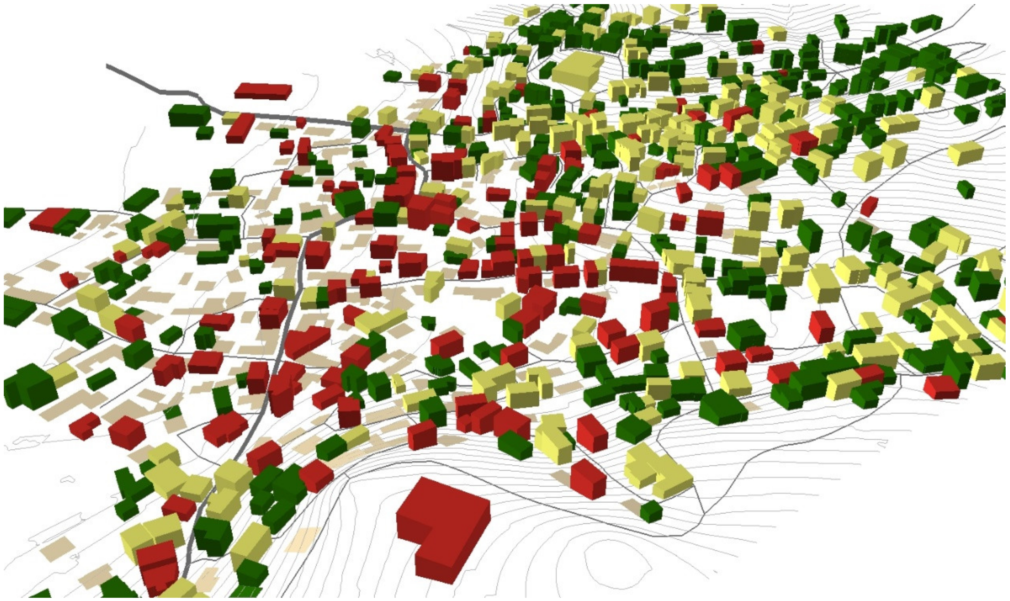
Despite the fact that remote sensing and geoinformation provide a wide spectrum of data acquisition and processing methods, there is no methodology to automatically or semi-automatically detect and map the demolished buildings of an earthquake-damaged urban area. Accurate 3D point cloud and DSM produced by UAS high resolution 4K video footage processing permit the development of algorithms for the detecting and 3D mapping of demolished buildings, as shown in Figure 13, with an accuracy of approximately 97% compared with field mapping. More analytically, 240 masonry buildings have been demolished from a total amount of 394 damaged buildings (RED-buildings), as shown in Table 2. The main reason for the misclassification of demolished buildings is the fact that, after a destructive earthquake, several buildings totally collapse, and their height is remarkably lower than standing ones. The comparison of heights after demolition does not differ significantly enough to be classified as a demolished building.
The results obtained by the present study show that DSM algorithm has fewer erroneously classified as demolished/non-demolished buildings than the 3D point cloud algorithm. It is evident that the raster format of the DSM provides the advantage of representing the surface of a parcel or building with a continuous surface and comparing the surface on a pixel by pixel basis. On the other hand, the methodology applied on the point clouds, based on a single statistic comparison for the whole object, does not capture any partial changes within each object (i.e., a partially collapsed building. Conclusively, both methods presented high overall accuracy in the classification of the demolished buildings without any significant omission and commission errors.

4. Conclusions

Spatial data can support both the earthquake-induced damage assessment [49] and recovery phase monitoring. The present study focused on the exploitation of UAS 4K-video footage to monitor and 3D-map the changes that occurred by the demolition process of a heavily damaged traditional village. The results proved that 4K-video footage acquired by the low altitude flight of a small UAS over a demolished area is a very safe, quick, low-cost and efficient method for capturing high-resolution optical information able to provide accurate 2D and 3D spatial datasets, such as orthophoto map, DSM, and 3D Point cloud. These datasets, algorithmically compared with the corresponding ones from previous flight campaigns (a few days after the destructive earthquake), proved to be efficient enough to automatically detect and map the demolished buildings among these dates.
By evaluating the results obtained with ground truth data, it can be concluded that the demolition process during the recovery phase after an earthquake can be monitored and accurately 3D mapped by taking advantage of geoinformation methods. Additionally, UAS flights that differ in acquisition date and flight parameters can produce comparable point clouds for change detection and demolition identification in recovery phase monitoring. These results indicate that the proposed methodology can assist post-earthquake management and reconstruction processes monitoring, since such 2D and 3D accurate spatial information can serve all stakeholders and national and local organizations. Future research will focus on developing a novel algorithm for debris calculation and mapping based on the same datasets and, more specifically, the 3D point clouds and DSMs on different epochs and debris weight measurements.
Debris processing plays a significant role in the beginning stages of the recovery process [50] and emerges as a critical issue in responding to a disaster closely intertwined with the environment [51]. When the damaged buildings are modern, and without significant architectural features, the demolition and reconstruction of new buildings is the optimal strategy. On the contrary, for heritage/traditional masonry buildings, such as Vrisa’s building stock, a strategy on the full recovery of the initial building stock is suggested. The optimal solution in the second case is the “anastylosis” reconstruction technique, employing a large amount of the original materials [52].

Author Contributions

Conceptualization, Nikolaos Soulakellis; Methodology, Nikolaos Soulakellis, Christos Vasilakos, and Dimitris Kavroudakis; Formal analysis, Christos Vasilakos and Dimitris Kavroudakis; Data curation, Ermioni-Eirini Papadopoulou, Apostolos Papakonstantinou, Olga Roussou and Themistoklis Kontos; Software, Stamatis Chatzistamatis and Ermioni-Eirini Papadopoulou; Visualization, Apostolos Papakonstantinou and Georgios Tataris; Writing-Original Draft Preparation, Nikolaos Soulakellis; Writing-Review & Editing, All. All authors have read and agreed to the published version of the manuscript.

Funding

This research was funded by North Aegean Region, Greece grant number 2917.

Acknowledgments

We thank the anonymous reviewers for providing constructive comments for improving the overall manuscript.

Conflicts of Interest

The authors declare no conflict of interest.

Appendix A

Figure A1. Different cases of omission and commission errors.
Ijgi 09 00447 g0a1aIjgi 09 00447 g0a1bIjgi 09 00447 g0a1c
Table A1. Classification matrix and accuracy results for demolished/non-demolished buildings for various thresholds of the difference between the mean heights of the two-point clouds. Columns are those modelled, and rows are the actual values (number of buildings).
Threshold0.511.522.533.5
01010101010101
054628474585814168264827382918291
112404237823324217481937316897144
Accuracy0.7340.9170.9780.9740.9520.9310.908
Sensitivity0.9960.9830.9670.9000.8010.9670.598
Specificity0.6580.8980.9810.9950.9960.9990.999
Kappa0.4610.7870.9360.9230.8540.7780.694

References

  1. Johnson, L.A.; Olshansky, R.B.; Olshansky, J.A. After Great Disasters: How Six Countries Managed Community Recovery; Lincoln Institute of Land Policy: Cambridge, MA, USA, 2016. [Google Scholar]
  2. Alexander, D. Principles of Emergency Planning and Management, 6th ed.; Dunedin Academic Press Ltd.: Edinburg, UK, 2012; ISBN 978-1-903544-10-5. [Google Scholar]
  3. Contreras, D.; Blaschke, T.; Kienberger, S.; Zeil, P. Myths and realities about the recovery of L’Aquila after the earthquake. Int. J. Disaster Risk Reduct. 2014, 8, 125–142. [Google Scholar] [CrossRef] [PubMed] [Green Version]
  4. Ubaura, M. Changes in Land Use After the Great East Japan Earthquake and Related Issues of Urban Form. In The 2011 Japan Earthquake and Tsunami: Reconstruction and Restoration: Insights and Assessment after 5 Years; Santiago-Fandiño, V., Sato, S., Maki, N., Iuchi, K., Eds.; Springer International Publishing: Cham, Switzerland, 2018; pp. 183–203. ISBN 978-3-319-58691-5. [Google Scholar]
  5. Bhanumurthy, V.; Shankar, G.J.; Rao, K.R.M.; Nagamani, P.V. Defining a framework for integration of geospatial technologies for emergency management. Geocarto Int. 2015, 30, 963–983. [Google Scholar] [CrossRef]
  6. Gutman, G.; Justice, C.; Sheffner, E.; Loveland, T. The NASA Land Cover and Land Use Change Program. In Land Change Science. Remote Sensing and Digital Image Processing vol 6; Gutman, G., Janetos, A.C., Justice, C.O., Moran, E.F., Mustard, J.F., Rindfuss, R.R., Skole, D.L., Turner, B.L.I., Cochrane, M.A., Eds.; Springer: Dordrecht, The Netherlands, 2004; pp. 17–29. [Google Scholar]
  7. Doi, A.; Oshida, K.; Takashima, Y.; Sakakibara, K.; Itoh, T. 3D Modeling of Reconstruction Plan at Sanriku Coast for Great East Japan Earthquake: Visualization of the Reconstruction Plan for Effective Information Sharing. In Proceedings of the 2016 19th International Conference on Network-Based Information Systems (NBiS), Ostrava, Czech Republic, 7–9 September 2016; pp. 397–400. [Google Scholar]
  8. Zekkos, D.; Greenwood, W.; Lynch, J.; Manousakis, J.; Athanasopoulos-Zekkos, A.; Clark, M.; Saroglou, C. Lessons Learned from The Application of UAV-Enabled Structure-From-Motion Photogrammetry in Geotechnical Engineering. ISSMGE Int. J. Geoengin. Case Hist. 2018, 4, 254–274. [Google Scholar]
  9. Dominici, D.; Alicandro, M.; Massimi, V. UAV photogrammetry in the post-earthquake scenario: Case studies in L’Aquila. Geomat. Nat. Hazards Risk 2017, 8, 87–103. [Google Scholar] [CrossRef] [Green Version]
  10. Boccardo, P.; Chiabrando, F.; Dutto, F.; Tonolo, F.; Lingua, A. UAV Deployment Exercise for Mapping Purposes: Evaluation of Emergency Response Applications. Sensors 2015, 15, 15717–15737. [Google Scholar] [CrossRef] [Green Version]
  11. Gomez, C.; Purdie, H. UAV—Based Photogrammetry and Geocomputing for Hazards and Disaster Risk Monitoring—A Review. Geoenviron. Disasters 2016, 3, 23. [Google Scholar] [CrossRef] [Green Version]
  12. Perouse, E.; Benedetti, L.; Fleury, J.; Rizza, M.; Puliti, I.; Billant, J.; Van der Woerd, J.; Feuillet, N.; Jacques, E.; Pace, B. Coseismic Slip Vectors of 24 August and 30 October 2016 Earthquakes in Central Italy: Oblique Slip and Regional Kinematic Implications. Tectonics 2018, 37, 3760–3781. [Google Scholar] [CrossRef] [Green Version]
  13. Calantropio, A.; Chiabrando, F.; Sammartano, G.; Spanò, A.; Teppati Losè, L. UAV strategies validation and remote sensing data for damage assessment in post-disaster scenarios. ISPRS Int. Arch. Photogramm. Remote Sens. Spat. Inf. Sci. 2018, XLII-3/W4, 121–128. [Google Scholar] [CrossRef] [Green Version]
  14. Yamazaki, F.; Kubo, K.; Tanabe, R.; Liu, W. Damage assessment and 3d modeling by UAV flights after the 2016 Kumamoto, Japan earthquake. In Proceedings of the 2017 IEEE International Geoscience and Remote Sensing Symposium (IGARSS), Fort Worth, TX, USA, 23–28 July 2017; pp. 3182–3185. [Google Scholar]
  15. Chiabrando, F.; Di Lolli, A.; Patrucco, G.; Spanò, A.; Sammartano, G.; Teppati Losè, L. Multitemporal 3D modelling for cultural heritage emergency during seismic events: damage assesment of s. agostino church in amatrice (RI). ISPRS Int. Arch. Photogramm. Remote Sens. Spat. Inf. Sci. 2017, XLII-5/W1, 69–76. [Google Scholar] [CrossRef] [Green Version]
  16. Zekkos, D.; Manousakis, J.; Athanasopoulos-Zekkos, A.; Clark, M.; Knoper, L.; Massey, C.; Archibald, G.; Greenwood, W.; Hemphill-Haley, M.; Rathje, E.; et al. Structure-from-Motion based 3D mapping of landslides & fault rupture sites during 2016 Kaikoura earthquake reconnaissance. In Proceedings of the Eleventh U.S. National Conference on Earthquake Engineering, Integrating Science, Engineering & Policy, Los Angeles, CA, USA, 25–29 June 2018. [Google Scholar]
  17. Soulakellis, N.; Tataris, G.; Papadopoulou, E.; Chatzistamatis, S.; Vasilakos, C.; Kavroudakis, D.; Roussou, O.; Papakonstantinou, A. Synergistic Exploitation of Geoinformation Methods for Post-earthquake 3D Mapping and Damage Assessment. In Intelligent Systems for Crisis Management; Altan, O., Chandra, M., Sunar, F., Tanzi, T.J., Eds.; Lecture Notes in Geoinformation and Cartography; Springer International Publishing: Cham, Switzerland, 2019; pp. 3–31. ISBN 978-3-030-05329-1. [Google Scholar]
  18. Vasilakos, C.; Chatzistamatis, S.; Roussou, O.; Soulakellis, N. Comparison of Terrestrial Photogrammetry and Terrestrial Laser Scanning for Earthquake Response Management. In Intelligent Systems for Crisis Management; Altan, O., Chandra, M., Sunar, F., Tanzi, T.J., Eds.; Lecture Notes in Geoinformation and Cartography; Springer International Publishing: Cham, Switzerland, 2019; pp. 33–57. ISBN 978-3-030-05329-1. [Google Scholar]
  19. Papakonstantinou, A.; Doukari, M.; Roussou, O.; Drolias, G.C.; Chaidas, K.; Moustakas, A.; Athanasis, N.; Topouzelis, K.; Soulakellis, N. UAS multi-camera rig for post-earthquake damage 3D geovisualization of Vrisa village. In Proceedings of the Sixth International Conference on Remote Sensing and Geoinformation of Environment (RSCy2018), Paphos, Cyprus, 26–29 March 2018. [Google Scholar]
  20. Chang, K.J.; Chan, Y.C.; Chen, R.F.; Hsieh, Y.C. Geomorphological evolution of landslides near an active normal fault in northern Taiwan, as revealed by lidar and unmanned aircraft system data. Nat. Hazards Earth Syst. Sci. 2018, 18, 709–727. [Google Scholar] [CrossRef] [Green Version]
  21. Peternel, T.; Kumelj, Š.; Oštir, K.; Komac, M. Monitoring the Potoška planina landslide (NW Slovenia) using UAV photogrammetry and tachymetric measurements. Landslides 2017, 14, 395–406. [Google Scholar] [CrossRef]
  22. Franke, K.W.; Lingwall, B.N.; Zimmaro, P.; Kayen, R.E.; Tommasi, P.; Chiabrando, F.; Santo, A. Phased reconnaissance approach to documenting landslides following the 2016 Central Italy Earthquakes. Earthq. Spectra 2018, 34, 1693–1719. [Google Scholar] [CrossRef]
  23. Santo, A.; Santangelo, N.; Forte, G.; De Falco, M. Post flash flood survey: The 14th and 15th october 2015 event in the paupisi-Solopaca area (Southern Italy). J. Maps 2016, 13, 19–25. [Google Scholar] [CrossRef] [Green Version]
  24. Quaritsch, M.; Kruggl, K.; Wischounig-Strucl, D.; Bhattacharya, S.; Shah, M.; Rinner, B. Networked UAVs as aerial sensor network for disaster management applications. e i Elektrotechnik und Informationstechnik 2010, 127, 56–63. [Google Scholar] [CrossRef]
  25. Contreras, D.; Blaschke, T.; Tiede, D.; Jilge, M. Monitoring recovery after earthquakes through the integration of remote sensing, GIS, and ground observations: The case of L’Aquila (Italy). Cartogr. Geogr. Inf. Sci. 2016, 43, 115–133. [Google Scholar] [CrossRef]
  26. Giordan, D.; Hayakawa, Y.S.; Nex, F.; Tarolli, P. Preface: The use of remotely piloted aircraft systems (RPAS) in monitoring applications and management of natural hazards. Nat. Hazards Earth Syst. Sci. 2018, 18, 3085–3087. [Google Scholar] [CrossRef]
  27. Hashemi-Parast, S.O.; Yamazaki, F.; Liu, W. Monitoring and evaluation of the urban reconstruction process in Bam, Iran, after the 2003 M w 6.6 earthquake. Nat. Hazards 2017, 85, 197–213. [Google Scholar] [CrossRef]
  28. Qin, R.; Tian, J.; Reinartz, P. 3D change detection—Approaches and applications. ISPRS J. Photogramm. Remote Sens. 2016, 122, 41–56. [Google Scholar] [CrossRef] [Green Version]
  29. Menderes, A.; Erener, A.; Sarp, G. Automatic Detection of Damaged Buildings after Earthquake Hazard by Using Remote Sensing and Information Technologies. Procedia Earth Planet. Sci. 2015, 15, 257–262. [Google Scholar] [CrossRef] [Green Version]
  30. Turker, M.; Cetinkaya, B. Automatic detection of earthquake-damaged buildings using DEMs created from pre- and post-earthquake stereo aerial photographs. Int. J. Remote Sens. 2005, 26, 823–832. [Google Scholar] [CrossRef]
  31. Vetrivel, A.; Gerke, M.; Kerle, N.; Vosselman, G. Identification of damage in buildings based on gaps in 3D point clouds from very high resolution oblique airborne images. ISPRS J. Photogramm. Remote Sens. 2015, 105, 61–78. [Google Scholar] [CrossRef]
  32. Kiratzi, A. The 12 June 2017 Mw 6.3 Lesvos Island (Aegean Sea) earthquake: Slip model and directivity estimated with finite-fault inversion. Tectonophysics 2018, 724–725, 1–10. [Google Scholar] [CrossRef]
  33. Papadimitriou, P.; Kassaras, I.; Kaviris, G.; Tselentis, G.-A.; Voulgaris, N.; Lekkas, E.; Chouliaras, G.; Evangelidis, C.; Pavlou, K.; Kapetanidis, V. The 12th June 2017 Mw = 6.3 Lesvos earthquake from detailed seismological observations. J. Geodyn. 2018, 115, 23–42. [Google Scholar] [CrossRef]
  34. Alexander, D.E. The L’Aquila Earthquake of 6 April 2009 and Italian Government Policy on Disaster Response. J. Nat. Resour. Policy Res. 2010, 2, 325–342. [Google Scholar] [CrossRef]
  35. Contreras, D.; Forino, G.; Blaschke, T. Measuring the progress of a recovery process after an earthquake: The case of L’aquila, Italy. Int. J. Disaster Risk Reduct. 2018, 28, 450–464. [Google Scholar] [CrossRef]
  36. Mavroulis, S.; Andreadakis, E.; Spyrou, N.I.; Antoniou, V.; Skourtsos, E.; Papadimitriou, P.; Kasssaras, I.; Kaviris, G.; Tselentis, G.A.; Voulgaris, N.; et al. UAV and GIS based rapid earthquake-induced building damage assessment and methodology for EMS-98 isoseismal map drawing: The June 12, 2017 Mw 6.3 Lesvos (Northeastern Aegean, Greece) earthquake. Int. J. Disaster Risk Reduct. 2019, 37, 20. [Google Scholar] [CrossRef]
  37. Chatzistamatis, S.; Kalaitzis, P.; Chaidas, K.; Chatzitheodorou, C.; Papadopoulou, E.E.; Tataris, G.; Soulakellis, N. Fusion of TLS and UAV photogrammetry data for post-earthquake 3D modeling of a cultural heritage church. In Proceedings of the Int. Arch. Photogramm. Remote Sens. Spatial Inf. Sci. 2018, XLII-3/W4, 143–150. [Google Scholar]
  38. Soulakellis, N.A.; Novak, I.D.; Zouros, N.; Lowman, P.; Yates, J. Fusing Landsat-5/TM imagery and shaded relief maps in tectonic and geomorphic mapping: Lesvos Island, Greece. Photogramm. Eng. Remote Sens. 2006, 72, 693–700. [Google Scholar] [CrossRef]
  39. Post Earthquake Damage and Usability Assessment of Buildings: Further Development and Applications. Final Report. European Commission—D.G. Environment, Civil Protection—EPPO. Available online: https://ec.europa.eu/echo/files/civil_protection/civil/act_prog_rep/peadab.pdf (accessed on 10 June 2020).
  40. Westoby, M.J.; Brasington, J.; Glasser, N.F.; Hambrey, M.J.; Reynolds, J.M. “Structure-from-Motion” photogrammetry: A low-cost, effective tool for geoscience applications. Geomorphology 2012, 179, 300–314. [Google Scholar] [CrossRef] [Green Version]
  41. Furukawa, Y.; Ponce, J. Accurate, Dense, and Robust Multiview Stereopsis. IEEE Trans. Pattern Anal. Mach. Intell. 2010, 32, 1362–1376. [Google Scholar] [CrossRef]
  42. Ramiya, A.M.; Nidamanuri, R.R.; Krishnan, R. Segmentation based building detection approach from LiDAR point cloud. Egypt. J. Remote Sens. Sp. Sci. 2017, 20, 71–77. [Google Scholar] [CrossRef] [Green Version]
  43. Cohen, J. A coefficient of agreement for nominal scales. Educ. Psychol. Meas. 1960, 20 SRC, 37–46. [Google Scholar] [CrossRef]
  44. Therneau, T.M.; Elizabeth, J.A. An Introduction to Recursive Partitioning Using the RPART Routines; Atkinson Mayo Foundation: Rochester, MN, USA, 2018. [Google Scholar]
  45. Zeileis, A.; Hothorn, T.; Hornik, K. Model-based recursive partitioning. J. Comput. Graph. Stat. 2008, 17, 492–514. [Google Scholar] [CrossRef] [Green Version]
  46. Zhang, H.; Singer, B.H. Recursive Partitioning and Applications; Springer: New York, NY, USA, 2010. [Google Scholar]
  47. CloudCompare (Version 2.X) [GPL Software]. Available online: http://www.cloudcompare.org/ (accessed on 10 June 2020).
  48. Hornik, K. The Comprehensive R Archive Network. Wiley Interdiscip. Rev. Comput. Stat. 2012, 4, 394–398. [Google Scholar] [CrossRef]
  49. Miano, A.; Jalayer, F.; Forte, G.; Santo, A. Empirical fragility curves based on random ground shaking fields: Employing Copernicus-EMS damage grading maps for 2016 amatrice sequence. In Proceedings of the 7th International Conference on Computational Methods in Structural Dynamics and Earthquake Engineering Methods in Structural Dynamics and Earthquake Engineering, Crete, Greece, 24–26 June 2019. [Google Scholar]
  50. Norton, T.R. Lessons Learned in Disaster Debris Management of the 2011 Great East Japan Earthquake and Tsunami. In The 2011 Japan Earthquake and Tsunami: Reconstruction and Restoration: Insights and Assessment after 5 Years; Santiago-Fandiño, V., Sato, S., Maki, N., Iuchi, K., Eds.; Springer International Publishing: Cham, Switzerland, 2018; pp. 67–88. ISBN 978-3-319-58691-5. [Google Scholar]
  51. Karunasena, G.; Amaratunga, D. Capacity building for post disaster construction and demolition waste management. Disaster Prev. Manag. Int. J. 2016, 25, 137–153. [Google Scholar] [CrossRef] [Green Version]
  52. Faleschini, F.; Zanini, M.A.; Hofer, L.; Zampieri, P.; Pellegrino, C. Sustainable management of demolition waste in post-quake recovery processes: The Italian experience. Int. J. Disaster Risk Reduct. 2017, 24, 172–182. [Google Scholar] [CrossRef]
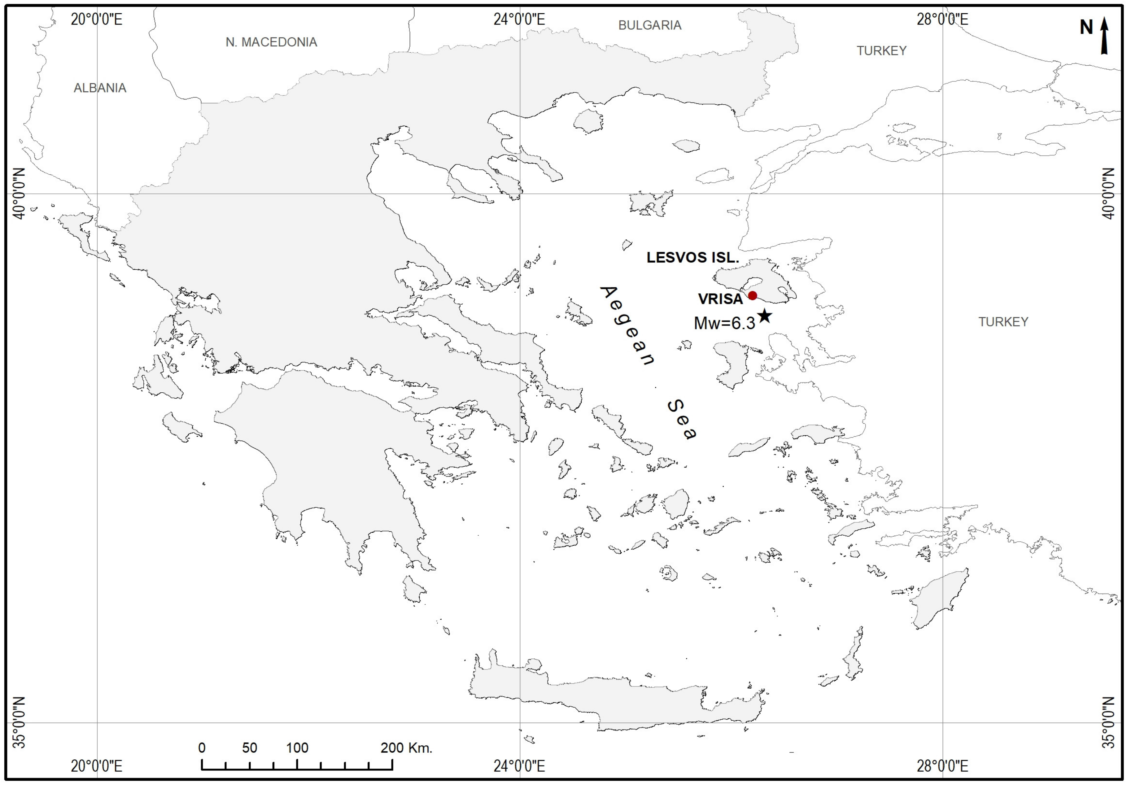
Figure 1. Simplified map of Greece presenting the location of Lesvos island, the Vrisa traditional settlement and the 12th of June 2017 (Mw 6.3) earthquake epicenter.
Ijgi 09 00447 g001
Figure 2. Damage assessment of Vrisa building stock after the final inspection by Greek ERO (black buildings present uninspected buildings).
Ijgi 09 00447 g002
Figure 3. The flight path designed for covering the area of interest as it appears on Google Earth satellite base map.
Ijgi 09 00447 g003
Figure 4. Flow chart of the methodology followed for 3D change monitoring and mapping of the demolition process at Vrisa settlement after the destructive earthquake.
Ijgi 09 00447 g004
Figure 5. GCP locations and error estimates. Z error is represented by ellipse color. X,Y errors are represented by ellipse shape. Estimated GCP locations are marked with a dot. (From Photoscan/Agisoft software report.)
Ijgi 09 00447 g005
Figure 6. The top orthophoto map of 3rd February 2019 derived from UAS 4K-video footage presents the demolished buildings mapped by photo interpretation and fieldwork. The bottom orthophoto map of 25th July 2017, derived by UAS high resolution images, presents the buildings which have been approved for demolition by the Greek-EPO.
Ijgi 09 00447 g006
Figure 7. (a) Part of the 3D point cloud of 3rd February 2019 derived from UAS 4K-video footage and (b) combination of two point clouds: (i) top 25th July 2017 presents a damaged building; (ii) bottom 3rd February 2019 presents the ground after the demolition.
Ijgi 09 00447 g007
Figure 8. The absolute distances in z axis for the total area of building stock. Warm colors depict the demolished buildings.
Ijgi 09 00447 g008
Figure 9. Trees over house roofs lead to the biggest negative values and, thus, errors in cloud to cloud comparison (a) point cloud of the study area and (b) cloud to cloud distance.
Ijgi 09 00447 g009
Figure 10. DSM of difference map created by subtracting the DSM of 3rd February 2019 with the DSM of 25th July 2017. Blue colors on map present negative height values, which refer to the demolished buildings. Three map-classes (i) −1.5 m to −6 m, (ii) −6 m to −9 m, and (iii) <−9 m, refer to one, two, and three-story buildings, respectively.
Ijgi 09 00447 g010
Figure 11. Accuracy, sensitivity and specificity for various thresholds—1.5 m of the mean height difference between the two acquisition dates provided the highest accuracy and Kappa coefficient.
Ijgi 09 00447 g011
Figure 12. Rules tree of the Recursive Partitioning approach for the binary classification of building structures to two classes: 1—Demolished (red) and 0—Non-Demolished (blue).
Ijgi 09 00447 g012
Figure 13. Three-dimensional map of the Vrisa traditional settlement presenting the result of the demolition process during the last few months. Color presents the damage category of the remaining buildings, while demolished buildings are presented as footprints.
Ijgi 09 00447 g013
Table 1. List of the number and GCPs used and X, Y, Z, and Total RMS.
NumberX—Easting Error (cm)Y—Northing Error (cm)Z—Altitude Error (cm)Total RMS (cm)
GCP101.81.20.22.2
Table 2. Statistical information concerning the demolished buildings on 3rd February 2019.
Number of BuildingsMaterialNumber of Stories
MasonryF/CMixed123
GREEN42735754111131072
YELLOW258242971071492
RED402394942031959
Total1087993722262345113
Demolished buildings
(3rd February 2019)
245240231311104