Article

An Intelligent Autonomous Morphing Decision Approach for Hypersonic Boost-Glide Vehicles Based on DNNs

1
School of Aeronautics and Astronautics, Dalian University of Technology, Dalian 116024, China
2
Beijing Aerospace Technology Institute, Beijing 100074, China
*
Author to whom correspondence should be addressed.
Aerospace 2023, 10(12), 1008; https://doi.org/10.3390/aerospace10121008
Submission received: 16 November 2023 / Accepted: 28 November 2023 / Published: 30 November 2023
(This article belongs to the Section Astronautics & Space Science)

Abstract

:
In addressing the morphing problem in vehicle flight, some scholars have primarily employed reinforcement learning methods to make morphing decisions based on task. However, they have not considered the constraints associated with the task process. The innovation of this article is that it proposes an intelligent morphing decision method based on deep neural networks (DNNs) for the autonomous morphing decision problem of hypersonic boost-glide morphing vehicles under process constraints. Firstly, we established a dynamic model of a hypersonic boost-glide morphing vehicle with a continuously variable sweep angle. Then, in order to address the decision optimality problem considering errors and the heat flux density constraint problem during the gliding process, interference was introduced to the datum trajectory in segments. Subsequently, re-optimization was performed to generate a trajectory sample library, which was used to train an intelligent decision-maker using a DNN. The simulation results demonstrated that, compared with the conventional programmatic morphing approach, the intelligent morphing decision maker could dynamically determine the sweep angle based on the current flight state, leading to improved range while still adhering to the heat flux density constraint. This validates the effectiveness and robustness of the proposed intelligent decision-maker.

1. Introduction

Hypersonic vehicles operate across a wide speed range, encompassing various complex tasks and processes. This speed domain spans from zero speed to subsonic, transonic, supersonic, and eventually hypersonic. Additionally, the airspace covered ranges from ground level, through the dense atmosphere, and extends to near space. The flight environment undergoes dramatic changes, involving horizontal takeoff, accelerated climb, cruise flight, turning maneuvers, glide, and autonomous landing, among others. If a fixed aircraft geometry is employed, it becomes challenging to meet the performance requirements of each flight stage.
Compared to traditional fixed-wing aircraft, the literature [1,2,3,4,5,6,7,8] highlights numerous advantages of variable geometry aircraft in adapting to different flight environments. Firstly, these aircraft can adjust their geometry according to the flight conditions, thereby increasing the lift–drag ratio to enhance range. Secondly, by undergoing morphing, they can alter their trajectory shape, reduce the reflective area, and improve penetration performance. Thirdly, the deformable mechanism can also serve as an auxiliary operation to coordinate control with the attack angle and bank angle, thus enhancing the aircraft’s rapid response capability.
However, the literature [9,10,11,12,13,14] highlights that the shape-changing process of morphing flight vehicles alters the aerodynamic characteristics and attitude control response, which affects the flight dynamics process. This change increases the control requirements and introduces additional constraints. It is necessary to study the optimal morphing timing and amplitude for comprehensive flight performance. Previous work [15] developed an approximation algorithm based on the sparse approximation principle to fit aerodynamic coefficients as functions of Mach, sweep angle, and attack angle. However, this approach requires pre-designing according to specific task requirements. The development of composite materials has opened up new possibilities for achieving morphing in aerospace applications. Numerous scholars have explored the utilization of smart materials to enable aircraft morphing. The authors of [16] investigated the application of soft polymeric materials in multi-axial morphing. The authors of [17] conducted finite element analysis on a novel GATOR skin to explore the relationship between skin structure and mechanical properties. The authors of [18] employed fused filament fabrication (FFF) 3D printing technology to manufacture complex shapes. However, the morphing of flexible wings presents significant challenges in terms of material requirements. The deformable skin must be capable of facilitating continuous and smooth large-scale morphing while maintaining adequate stiffness for preserving wing shape and bearing loads. Existing skin materials face issues during morphing transitions, resulting in discontinuities on the wing surface, imprecise morphing, and a negative impact on aerodynamic efficiency. Furthermore, there are also concerns regarding morphing stiffness and reliability [19,20,21,22,23].
To achieve intelligence and autonomy in morphing flight vehicles, it is essential to dynamically adjust the morphing strategy according to flight conditions and task demands. Reinforcement learning algorithms provide an interactive learning framework between an agent and its environment, enabling the agent to discover optimal actions through trial and error to maximize rewards and adapt to changing environments. Consequently, reinforcement learning methods are often employed as effective approaches for determining shape decisions in morphing flight vehicles. For instance, the authors of [24] employed an AC algorithm based on reinforcement learning to solve optimal aircraft shapes. Another study [25] approximated the KNN method with a continuous function and combined Q-learning with nonlinear dynamic inverse control (NDI), yielding favorable control effects. Additionally, Q-learning was utilized in [26] to make decisions based on the forward sweep angle of UAVs in the mission profile. In [27], an adaptive control method based on Q-learning was proposed for variable sweep angle aircraft, determining optimal morphing strategies for specific mission profiles. Moreover, [28,29] conducted semi-physical simulation experiments on deformed wings using the deep deterministic policy gradient algorithm (DDPG) to design optimal wing shapes. Furthermore, in [30], the DDPGwTC algorithm was proposed, which employed a task classifier based on the long short-term memory recurrent neural network (LSTM) theory. Corresponding reward functions were designed to make decisions based on different task types. The aircraft’s state data are fed into the input layer of the LSTM network. Utilizing information such as the current velocity, altitude, instruction velocity, instruction altitude, and changes in velocity and altitude during the given time period, the LSTM network classifies the aircraft’s present flight phase. To mitigate overfitting, a dropout layer is incorporated before the fully connected layer. Ultimately, the classification layer outputs the specific task type (e.g., climb, cruise).
In the actual morphing process, the continuous change in the aircraft’s shape poses a challenge for the Q-learning method, which operates in discrete state and action spaces. This limitation prevents it from fully leveraging its flight performance across variable ranges. Additionally, there is a tendency for the DDPG to overestimate Q-values during estimation. Moreover, the decision-making process determining the sweep angle through reinforcement learning heavily relies on the choice of reward function, making training convergence difficult to achieve. Furthermore, the aforementioned research solely focuses on sweep angle decisions for the mission profile without considering morphing decisions under process constraints. Hypersonic gliding aircraft experience a significant temperature rise as a result of the conversion of a portion of their kinetic energy into internal energy when passing through shockwaves, leading to severe aerodynamic heating challenges. During the trajectory design phase, a morphing flight vehicle can adapt its aerodynamic characteristics by adjusting the sweep angle. This morphing allows the hypersonic aircraft to evade limitations on heat flux density while simultaneously achieving the objective of increasing gliding distance. In view of the above problems, this paper studies the morphing timing and the morphing amplitude of the decision.
To address the aforementioned challenges and achieve the optimization goal of the optimal glide range, this paper proposes an intelligent morphing decision-maker based on deep neural networks (DNNs). This decision-maker takes into consideration the heat flux density constraint during glide and incorporates the Gaussian pseudo-spectrum method. The main innovations of this approach are as follows:
(1)
Compared with reinforcement learning, the Gaussian pseudo-spectrum method can obtain a continuous sequence of state quantities and control quantities while considering state constraints, giving full play to the full potential in the variable range of sweep angle.
(2)
Instead of fitting the sweep angle as a function of flight state quantity, a DNN essentially realizes a mapping function from input to output, which is suitable for solving problems with complex internal mechanisms. It can realize online rapid decision-making of the sweep angle according to flight status.
(3)
Compared with an ordinary glide vehicle, hypersonic boost-glide vehicles have additional propulsion systems and control dimensions.
The structure of the paper is as follows: in Section 2, we establish the dynamic model of the hypersonic morphing flight vehicle. In Section 3, we propose an intelligent morphing decision method based on a DNN considering the heat flux density constraint during gliding. In Section 4, the above method is verified by adding interference.

2. Hypersonic Morphing Vehicle Dynamics Modeling

This paper focuses on a hypersonic glide vehicle capable of continuously adjusting its sweep angle. The variable sweep angle was accomplished through a spring-slider mechanism. This mechanism comprised springs, sliders, and slide rods. The slide rod was affixed to the wing, allowing the slider to move along the rod, with the spring connecting the fuselage and the slider. When the aircraft was in flight, aerodynamic drag affected the wing, causing the spring to compress and thereby altering the sweep angle. This design obviated the necessity for a convoluted transmission system within the fuselage, thus occupying minimal space.
The purpose of this research was to enhance aerodynamic performance during gliding by modifying the sweep angle based on the vehicle’s flight state. Taking the center of mass of the flight vehicle in its un-morphing state as the origin, we established a dynamic model in the body coordinate system. The origin of the body coordinate system was fixed at the center of the gravity position when the sweep angle was at its minimum, and the aircraft was divided into the fuselage (including the tail) and the left and right wings. In the body coordinate system, the expressions for the momentum P and the momentum moment H of the morphing flight vehicle are as follows:
P = m V b o d y + S ˙ + ω × S H = S × V + I ω + i = 1 2 ( 1 m i S i × δ S i δ t + I i ω i )
In the above formula, the variables are defined as follows: m represents the total mass of the morphing aircraft, V b o d y = [ u , v , w ] T represents the airspeed of the morphing aircraft, ω = [ p , q , r ] T denotes the angular velocity of the morphing aircraft about the body axis with respect to the ground coordinate system. I represents the total moment of inertia of the morphing aircraft in the body coordinate system, and S denotes the total static moment of the morphing aircraft about the origin of the body coordinate system. Specifically, S i = r i d m represents the static moment of the left and right wings of the morphing aircraft in the body coordinate system, while I i represents the moment of inertia of the morphing components in the body coordinate system. Furthermore, ω i represents the angular velocity of the morphing component.
According to the principles of momentum and angular momentum, the following can be derived:
F = P ˙ M = H ˙ + V × S ˙
Substituting Equation (1) yields the dynamic vector equation for the morphing aircraft as:
F = m ( V ˙ + ω × V ) + δ ω δ t × S + 2 ω × δ S δ t + ω × ( ω × S ) + δ 2 S δ t M = I δ ω δ t + δ I δ t ω + ω × ( I ω ) + S × δ V δ t + S × ( ω × V ) + i = 1 2 I i δ ω i δ t + δ I i δ t ω i + ω i × ( I i ω i ) + 1 m i [ S i × δ 2 S i δ t 2 + ω × ( S i × δ S i δ t ) ]
Decompose the total external force F and external moment M acting on the morphing sweep angle aircraft into the body coordinate system. Obtain the nonlinear dynamic equations for the morphing sweep angle aircraft.
F x = m ( u ˙ + q w r v ) + q ˙ S z r ˙ S y + 2 ( q S ˙ z r S ˙ y ) + q ( p S y q S x ) r ( r S x p S z ) + S ¨ x F y = m ( v ˙ + r u p w ) + r ˙ S x p ˙ S z + 2 ( r S ˙ x p S ˙ z ) + r ( q S z r S y ) p ( p S y q S x ) + S ¨ y F z = m ( w ˙ + p v q u ) + p ˙ S y q ˙ S x + 2 ( p S ˙ y q S ˙ x ) + p ( p S y q S x ) q ( q S z r S y ) + S ¨ z
M x = I x p ˙ + I ˙ x p + q ( I z r I z x p ) r I y q + S y w ˙ S z v ˙ + S y r w S x r w   + i = 1 2 I i x ω ˙ i x r I i y ω i y + 1 m i r ( S i x S ˙ i z S i z S ˙ i x ) M y = I y q ˙ + I ˙ y q + r ( I x p I z x r ) p ( I z r I z x p ) + S z u ˙ S x w ˙ + S z p u S x r w   + i = 1 2 I i y ω ˙ i y + I ˙ i y ω i y + 1 m i ( S i z S ˙ i x S i x S ˙ i z ) M z = I z r ˙ + I ˙ z r + p I y q q ( I x p I z x r ) + S x v ˙ S y w ˙ + S x q v S y p u   + i = 1 2 I i z ω ˙ i z + p I i y ω i y + 1 m i p ( S i z S ˙ i x S i x S ˙ i z )
In Equation (4), S x , S y , S z represents the additional force generated by the movement of the aircraft’s center of mass, S ˙ x , S ˙ y , S ˙ z denotes the additional force generated by the velocity of the center of mass movement, and S ¨ x , S ¨ y , S ¨ z represents the additional force generated by the acceleration of the center of mass movement. In Equation (5), S x , S y , S z represents the additional moment generated by the movement of the aircraft’s center of mass, S ˙ x , S ˙ y , S ˙ z denotes the additional moment generated by the velocity of the center of mass movement, and S ¨ x , S ¨ y , S ¨ z represents the additional moment generated by the acceleration of the center of mass movement. S i x , S i y , S i z ( i = 1 , 2 ) denotes the additional moment generated by the change in the center of mass position of the aircraft due to the sweep of the wings, S ˙ i x , S ˙ i y , S ˙ i z , S ¨ i x , S ¨ i y , S ¨ i z ( i = 1 , 2 ) denotes the additional force generated by the velocity and acceleration of the movement of the wing’s center of mass.
For a morphing sweep aircraft with longitudinal body symmetry and a synchronously symmetric wing sweep, the center of mass of the aircraft, denoted as “ r ( x , y , z ) ” remains unchanged along the O y and O z axes; i.e., r y = r z = 0 , S y = S z = 0 . The entire aircraft’s center of mass changes only along the x-axis, S x 0 . Furthermore, the wing’s center of mass varies within the plane O x y , with no variation along the z-axis, resulting in S i z = 0 .
Finally, by transforming the aforementioned dynamic equations into the ground coordinate system, we can obtain: [31,32,33].
V ˙ = T cos α D m g sin θ m θ ˙ = T sin α + L m g cos θ m V ψ ˙ V = ( T sin α + L ) sin γ V m V cos θ X ˙ = V cos ( θ ) cos ( ψ V ) Re r Y ˙ = V cos ( θ ) sin ( ψ V ) Re r h ˙ = V sin ( θ ) m ˙ = T g I s p ψ V = asin ( sin ( γ ) cos ( θ ) ) cos ϑ ϑ = α + θ
In the formula, V represents the speed, h represents the altitude, θ represents the trajectory angle, ϑ represents the pitching angle, α represents the attack angle, m  represents the mass of the hypersonic morphing vehicle, I s p represents the momentum, and g represents the gravity coefficient. Due to the glide starting from near space, the gravitational coefficient at the altitude of the aircraft differs from that on the ground. During the gliding process, the influence of latitude is ignored, and it is assumed that the gravity experienced by the aircraft is only related to its altitude, which can be represented as g = g ( H ) . ψ V represents the trajectory declination angle, γ represents the bank angle, γ V represents the speed bank angle, X and Y respectively represent the displacement in two directions, D represents the drag, and T and L respectively represent the engine thrust and lift. It is believed that there is a proportional relationship between the throttle coefficient K r and the engine thrust; i.e., when K r = 1 , the engine thrust reaches its maximum value, and when K r = 0 , the engine thrust is 0. Re represents the Earth’s radius, r = Re + h , and r is the distance between the vehicle and the center of the Earth.
Lift L and drag D can be expressed as follows:
L = q S C L D = q S C D
q = 1 2 ρ V 2 is the dynamic pressure in the environment, and S represents the reference area of the hypersonic vehicle; ρ is the atmospheric density at the altitude of the hypersonic vehicle, and C L and C D represent the lift coefficient and drag coefficient respectively.
For high-altitude, high-Mach number hypersonic aircraft, the lift coefficient is not only related to the geometric configuration and Mach number of the aircraft itself but also closely related to the Reynolds number, denoted as C L = f ( Re , M a , g e o m e t r y ) . Similarly, the drag coefficient follows the same pattern: C D = f ( Re , M a , g e o m e t r y ) .
To study the influence of the sweep angle on the lift and drag, 7 Ma, 12 Ma, 15 Ma, 20 Ma, and 25 Ma were selected as the working points to analyze the lift coefficient and lift coefficient at sweep angles of 63° and 78°. The result is shown in Figure 1.
From the standpoint of lift requirements, aircraft commence gliding as they enter near-space. Owing to the rarefied atmosphere and diminished dynamic pressure at high altitudes, a small sweep angle is employed during gliding. As the aircraft’s altitude and speed progressively diminish throughout the gliding phase, the air density escalates, leading to a rise in dynamic pressure and a diminished need for lift surfaces, thereby necessitating a larger sweep angle for flight.

3. Intelligent Decision-Making Method Based on a DNN

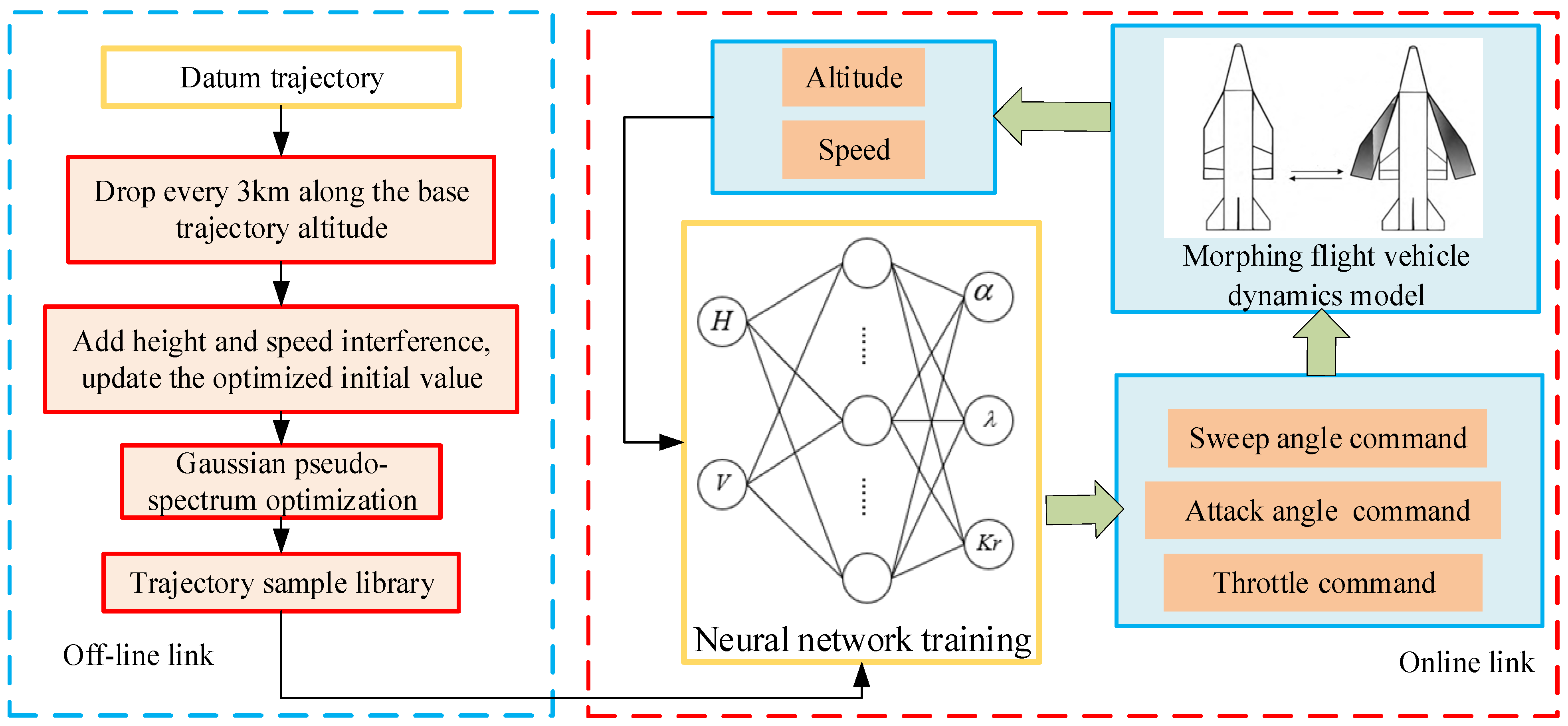
The Gaussian pseudo-spectrum method can effectively plan an optimal trajectory that satisfies given performance indices and constraints, even in the presence of initial value deviation and arbitrary disturbance. This paper harnesses the strengths of the Gaussian pseudo-spectrum method. A segmented trajectory sample library was generated based on the datum trajectory with added perturbations. It leveraged the powerful learning capabilities of a DNN to design an intelligent decision-maker for the sweep angle during the glide phase of a boost-glide hypersonic morphing vehicle. The overall flow chart of the proposed approach is illustrated below, where λ represents the sweep angle and K r represents engine throttle. The overall scheme is shown in Figure 2.

3.1. Gaussian Pseudo-Spectral Principle

The heat flux density is a fundamental parameter that reflects the aerothermal effects of a hypersonic vehicle. It is influenced by various factors, including the aircraft’s shape, aerodynamic layout, flight attitude, and flight Mach number. Previous studies have demonstrated that the leading-edge heat flux density of an aircraft decreases linearly as the sweep angle increases. Utilizing the variable sweep method can enhance the aerothermal characteristics of hypersonic vehicle, with a highly swept wing exhibiting superior aerothermal properties [30].
Q = k q ρ 0.5 V 3.15 Q max
In this equation, Q represents the heat flux of the aircraft, k q is a coefficient related to the aircraft shape, ρ represents the atmospheric density, V represents the current flight velocity, and Q max represents the maximum tolerable heat flux. In this paper, Q max = 5   MW / m 2 .
The essence of the Gaussian pseudo-spectral method is a direct approach that simultaneously considers discrete control variables and state variables. This method is also known as the collocation method or DCNLP (direct collocation with nonlinear programming). Eventually, the optimal control problem is transformed into a nonlinear programming problem with constraints and solved using sequential quadratic programming. The basic principle can be described as follows [33,34,35].

3.1.1. Time Domain Transformation

The time domain of continuous trajectory optimization problems is generally t t 0 , t f , while the pseudo-spectral method is used to distribute the discrete states and control variables in the time domain t 1 , 1 . As a result, a transformation of the time interval becomes necessary. The time domain transformation is expressed as follows:
τ = 2 t t f t 0 t f + t 0 t f t 0
The optimal control problem can be expressed as follows:
J = M x τ 0 , τ 0 , x τ f , τ f + t f t 0 2 τ 0 τ f f ( x ( τ ) , u ( τ ) ) d τ s . t . x ˙ = t f t 0 2 f ^ x τ , u τ , τ ϕ x τ 0 , x τ f ; t 0 , t f = 0 C x τ , u τ , τ ; t 0 , t f 0 ; m = 1 , 2

3.1.2. The Optimal Control Problem Is Parameterized to the NLP Problem

  • State quantity discretization.
Construct Lagrange polynomials, then select Gaussian discrete points τ 1 , τ 2 τ N ; they are the roots of the Lagrange polynomial. The value of the state quantity at these N points is X ( τ 1 ) , X ( τ 2 ) X ( τ N ) . The state variable approximated by the Grange interpolation polynomial is abbreviated as:
X N 1 ( τ ) = i = 1 N l i ( τ ) X ( τ i )
In order to find the derivative of state quantity at discrete point τ 1 , τ 2 τ N , take the derivative of the above formula to obtain the derivative value at the Gaussian discrete point:
X τ = i = 0 N l ˙ i τ k X τ i k = 0 , , N
Among them, the state differential matrix l ˙ k i is as follows:
l ˙ k i = L N 1 t k L N 1 t i 1 t k t i , k i , N ( N 1 ) 4 , k = i = 1 , N ( N 1 ) 4 , k = i = N , 0 , k , i   is   else
Then the differential equation in Equation (10) becomes
i = 0 N l ˙ i τ k x ( τ i ) = t f t 0 2 f x ( τ k ) , u ( τ k ) , τ k
  • Performance indicators discretization.
The integral part of the performance index function adopts the Gaussian quadrature method, and the numerical integral is expressed as follows:
1 1 f ( x ( τ ) , u ( τ ) , τ ) d τ = k = 0 N f ( τ k ) w k
In the formula, w k is the Gaussian weight
w k = 2 n ( n + 1 ) 1 L n τ k 2 k
Then, the performance indicator in Equation (10) becomes
J ( x , u , t f ) = t f t 0 2 k = 0 N f ( τ k ) w k
  • Discretization of boundary conditions.
The boundary conditions ϕ x 0 , u 0 , 1 ; x n , u n , 1 = 0 can be written as
ϕ ( x 0 ) = x ( τ 0 )    ϕ ( u 0 ) = u ( τ 0 ) ϕ ( x n ) = x ( τ n )    ϕ ( u n ) = u ( τ n )
Finally, we obtain
min   J ( x , u , t f ) = M x n , 1 + t f t 0 2 k = 0 N f ( τ k ) w k s . t . i = 0 N l ˙ i τ k x ( τ i ) = t f t 0 2 f x ( τ k ) , u ( τ k ) , τ k ϕ ( x 0 ) = x ( τ 0 )    ϕ ( u 0 ) = u ( τ 0 ) ϕ ( x n ) = x ( τ n )    ϕ ( u n ) = u ( τ n ) C x i , u i , τ i 0 ,    i = 0 , 1 n
Through the above transformation, the optimal control problem can be transformed into a constrained nonlinear programming problem for sequential quadratic programming.

3.2. Segmentation Optimization Based on Gaussian Pseudo-Spectrum Method

During the gliding process of a hypersonic vehicle, thermal effects pose significant challenges to the structural integrity. The Gaussian pseudo-spectral method can be employed to plan optimal trajectories that meet mission objectives while considering process constraints.
Due to interference during actual flight, the morphing strategy designed under the initial entry condition cannot guarantee that the hypersonic vehicle will maintain its optimal sweep angle after deviations in altitude or speed. Moreover, when altitude and velocity deviate, the reference trajectory obtained from optimizing the nominal entry condition may no longer be the optimal trajectory for the current state. Therefore, when deviations occur, the hypersonic vehicle should not adhere to the reference trajectory, but instead redesign the trajectory based on the current state. However, the Gauss pseudo-spectral method poses a significant computational burden when solving for optimal trajectories. This burden may exceed the capabilities of onboard computers, hindering real-time trajectory planning. Therefore, a method is proposed to offline segment the reference trajectory, accounting for potential disturbances that the aircraft may encounter. Height and velocity disturbances are incorporated into each segment, resulting in multiple sets of entry conditions influenced by disturbances. These disturbed trajectories are then optimized to obtain the optimal control inputs. Simultaneously, the optimized interference trajectories satisfy the constraint of heat flux density. All sample trajectories meet the heat flux density constraint, ensuring that the trained neural network exhibits this characteristic. To facilitate rapid decision-making during the online phase of the aircraft, a DNN network is trained.
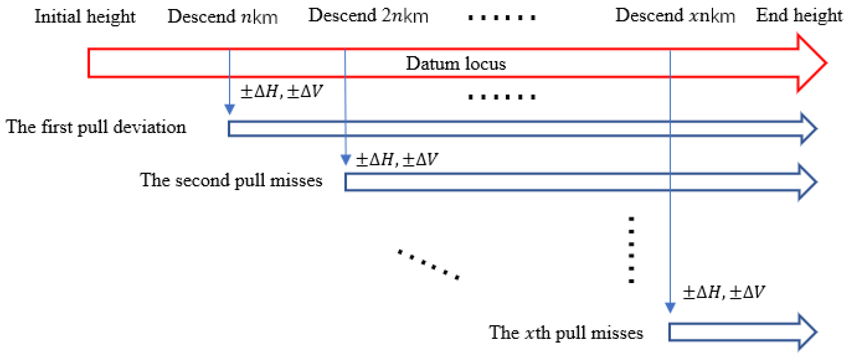
To ensure the optimal determination of the subsequent sweep angle, interference is introduced to the altitude and speed at regular intervals (n km) on the basis of the reference entry condition’s optimized datum trajectory. The re-optimization process (as shown in Figure 3 is conducted. The state quantities ( H , V ) on the disturbed trajectory and the datum trajectory obtained through the pseudo-spectrum method are utilized as input parameters for the neural network. The output parameters consist of the sweep angle λ , attack angle α , and throttle K r . The overall flow chart is displayed in Figure 4.
Overall program implementation steps:
(1)
Based on the optimized reference trajectory for entry conditions, height and velocity disturbances are applied to the hypersonic aircraft every 3 km, resulting in multiple entry conditions.
(2)
Based on the multi-group deviation entry conditions, the Gaussian pseudo-spectrum method is employed to optimize the trajectory multiple times. This process generates data pairs, consisting of the state quantity ( H , V ) and the output quantity [ λ , α , K r ] , at each moment. These data pairs are then used to construct a trajectory sample library.
(3)
Use the neural network to approximate the complex nonlinear model between the state quantity and the control quantity; that is, [ λ , α , K r ] = f ( H , V ) , where f represents neural network approximation. Steps (1)~(3) are completed offline.
(4)
The neural network intelligent morphing decision-maker and the hypersonic vehicle motion model form a closed loop. The neural network decision-maker receives the flight state data, and output the sweep angle and other control quantities.

3.3. DNN Training Based on Trajectory Sample Database

Deep neural networks (DNNs) are a type of multi-layer unsupervised neural network that utilizes the output features from the previous layer as input for the next layer, enabling feature learning (As shown in Figure 5). In practice, deep modeling can accurately and efficiently represent complex nonlinear problems, surpassing shallow modeling approaches. By increasing the number of hidden layers, the DNN reduces the total number of hidden layer neurons and significantly improves training efficiency. The relationship between height, Mach number, and sweep angle is not simply linear, thereby requiring the deep network structure of DNN to effectively solve complex nonlinear problems. Given the abundance of trajectory data, the DNN network is employed for training to achieve a good fitting effect of complex nonlinear relations [36,37,38,39,40].

3.3.1. Forward Propagation

Starting from the second layer, each neuron receives input from all the neurons in the layer above it. Assuming a total of m neurons in layer l 1 , the output a j l of the j th neuron in layer l can be expressed as follows:
a j l = σ ( z j l ) = σ ( k = 1 m ω j k l a k l 1 + b j l )
In the above formula, σ represents the activation function, generally an S-type function, usually sigmoid or tanh, w j k l represents the weight, b j l represents the deviation, and a k l 1 represents the network output of the previous layer.

3.3.2. Error Backpropagation

A DNN usually chooses the mean square error as a loss function, expressed as follows:
J ( W , b , x , y ) = 1 2 a L y 2 2
Among these, a L and y are vectors with output layer feature dimension n o u t , and S 2 is the L2 norm of S . x represents the input vector, y represents the output vector.
After the loss function is obtained, the gradient descent method is used to iterate W and b of each layer.
The first output layer is layer l . Note that W and b of the output layer satisfy the following formula:
a L = σ ( z L ) = σ ( W L a L 1 + b L )
For the parameters of the output layer, the loss function becomes
J ( W , b , x , y ) = 1 2 a L y 2 2 = 1 2 σ ( W L a L 1 + b L ) y 2 2
Solving the gradient of W and b , we obtain
J ( W ,   b ,   x ,   y ) W L = [ ( a L y ) σ ( z L ) ] ( a L 1 ) T J ( W ,   b ,   x ,   y ) b L = ( a L y ) σ ( z L )
After calculating the gradient of the output layer, it is also necessary to calculate the gradient of the previous layers. Note that
J ( W , b , x , y ) W L = J ( W , b , x , y ) z L z L W L
In the above formula, z l is the output of layer l , the gradient of layer l can be obtained by calculating the value of J ( W ,   b ,   x ,   y ) z l .
J ( W ,   b ,   x ,   y ) W l = J ( W ,   b ,   x ,   y ) z l z l W l = J ( W ,   b ,   x ,   y ) z l ( a l 1 ) T J ( W ,   b ,   x ,   y ) b l = J ( W ,   b ,   x ,   y ) z l z l b l = J ( W ,   b ,   x ,   y ) z l
At this point, all the gradients of the first layer are calculated, and the back propagation can be carried out according to the gradient value.
In a DNN, the error is obtained through forward propagation, and the weights are adjusted through reverse propagation. This process continues with subsequent iterations of forward and reverse propagation until the optimal solution is obtained.
The entire process of intelligent morphing decision-making can be represented by the following pseudo-code, as shown in Table 1.
In the generation of trajectory samples, the trajectory is segmented based on a reference trajectory. Disturbances are introduced at the segment points, and the trajectory is optimized once again. Subsequently, the trajectory samples are trained using a deep neural network. The network weights are continuously adjusted based on training errors until the desired level of precision is achieved. Upon completion of the training process, the trained decision-maker is applied to the online phase. It receives the flight status of the aircraft as input and outputs control commands.

4. Hypersonic Vehicle Morphing Decision Simulation

4.1. Generation of Datum Trajectory and Interference Trajectory

For conventional three-dimensional trajectory optimization, there are four optimal control parameters: attack angle, bank angle, throttle coefficient, and sweep angle morphing rate. By presetting the fixed bank angle instruction, the optimization dimension is reduced, and only other control quantities are optimized, thus improving the optimization speed. The simulation boundary constraints of the Gaussian pseudo-spectrum method for generating reference trajectory are shown in the Table 2.
The control constraints include attack angle α , sweep angle morphing rate λ ˙ , throttle coefficient K r , and process constrained heat flux density Q max . X f and Y f represent the terminal point displacement in both directions, and the optimization objective is the displacement distance is the farthest:
J = max ( Z f + Y f ) s . t 0 α 40 2.2 λ ˙ 2.2 0 K r 1 Q max 5   MW / m 2
The optimized datum trajectory is shown in Figure 6.
The hypersonic morphing vehicle’s reference trajectory descends from an altitude of 80 km to 45 km. The altitude decreases by 3 km each time, then introducing a disturbance of ± 100   m / s in speed and ± 500   m in altitude. The disturbance points are re-optimized, resulting in a total of 44 optimized disturbance trajectories. The state quantity ( H , V ) of all trajectories is taken as a network input, and the sweep angle λ , attack angle α , and throttle coefficient K r are taken as network outputs. Neural network training is conducted, and the structure and training results of the neural network are shown in Table 3 and Figure 7.
Using the same dataset, training was separately conducted on DNN and BPNN models with identical settings for training parameters, except for the network structures. After completing the training, the same test set was used for evaluation, and the root mean square error (RMSE) values obtained from the two networks’ fittings are shown in the Table 4. Due to its deeper network structure, the DNN exhibited better training performance. The RMSE values for all predictions were lower compared to those of the BP network.

4.2. Intelligent Morphing Decision and Instruction Morphing Decision Comparison Simulation

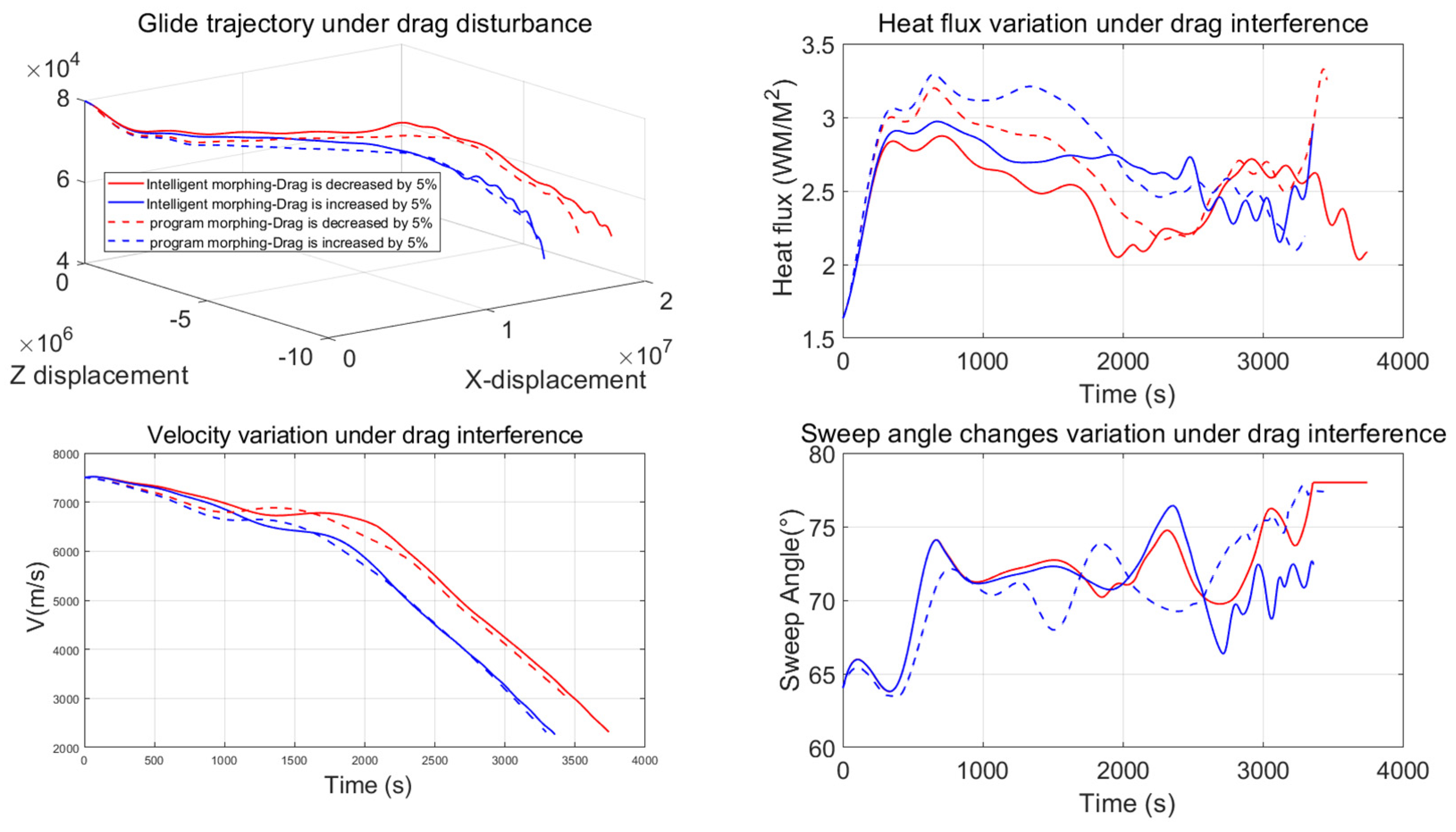
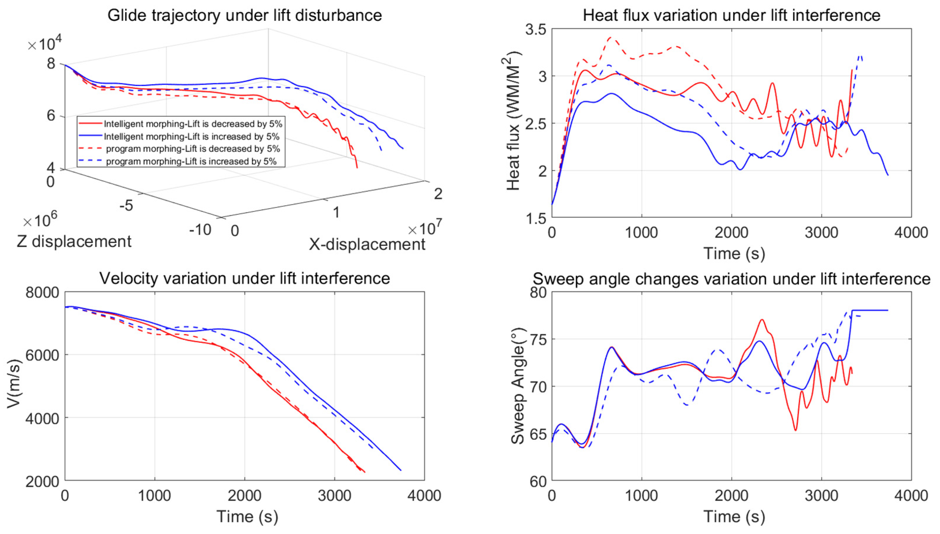
The conventional morphing decision is a programmed decision approach that involves utilizing the prior aerodynamic data of the morphing hypersonic vehicle. This method calculates the optimal aerodynamic shape for different tasks and switches to the corresponding shape based on the specific environmental requirements during task execution. The control instructions for program decisions comprise the sweep angle command, attack angle, and throttle command derived from the reference trajectory. The control instructions for programmed decision-making refer to the benchmark trajectory control instructions optimized using the Gaussian pseudo-spectral method discussed in Section 4.1. Intelligent decision-making is implemented during actual flight processes, where the aircraft adapts and makes real-time decisions based on its own state, aiming to improve range under uncertain conditions. In order to validate the performance of the intelligent decision-maker, 5% lift disturbance and drag disturbance were respectively introduced during the gliding process. The programmatic morphing utilized control commands optimized through the Gaussian pseudo-spectral method, while the intelligent morphing relied on real-time control commands output by the intelligent decision-maker. A comparison of the gliding range between the two methods is presented in Table 5, Figure 8 and Figure 9.
This simulation study was conducted using MATLAB 2021. When employing deep neural networks (DNNs) for decision-making on the sweep angle under four different interference conditions, an average of 3548 decisions were made within 15.1 s, with each decision taking 0.004 s. The decision speed was exceptionally fast. Furthermore, the increase in time cost compared to procedural decision-making remained within an acceptable range.
As seen in the table above, the intelligent morphing decision-making method demonstrated a greater glide range compared to the program decision-making method when lift and drag were interfered with. Specifically, when the lift was increased by 5%, the intelligent morphing method exhibited the highest gain compared to the program morphing method, resulting in an extended range of approximately 1240 km, which corresponded to a 6% increase. On the other hand, when the lift was reduced by 5%, the programmed morphing reached a maximum peak heat flux density of 3.4 MW/m2. In contrast, the intelligent morphing showed a significantly lower peak heat flux density of only 3.05 MW/m2 under the same interference. This reduction in peak heat flux amounted to approximately 10.2%, highlighting the robustness of the intelligent decision-making morphing method.

5. Conclusions

This paper proposes an intelligent morphing decision-making method based on DNNs for morphing the sweep of wings in hypersonic glide vehicles. The objective of this method is to achieve maximum displacement while considering the process constraints during the glide process. The simulation results demonstrated that by incorporating the same interference into the glide process, the hypersonic morphing vehicle could intelligently determine the optimal sweep angle based on its current flight state. The glide range could be increased compared to the program decision method. Additionally, the heat flux density remained within the specified constraints, thus proving the effectiveness and robustness of the intelligent decision-maker.

6. Limitations and Potential Future Directions

Hypersonic morphing vehicles represent the future development trend of advanced aircraft, carrying immense potential and research value. This paper focuses on the study of morphing decision-making for hypersonic morphing vehicles and has yielded significant results. However, to further advance this research, the following aspects require additional investigation:
(1)
Integration of control methods: While this paper primarily concentrates on shape decision-making, it is crucial to acknowledge that shape changes can significantly impact the aircraft’s aerodynamic characteristics. Subsequent research should involve the design of advanced control methods, such as LPV control and adaptive control, to improve the tracking effect and enhance the morphing stability of the aircraft.
(2)
Conducting physical experiments: The research on hypersonic morphing vehicles in this paper is primarily based on simulation experiments. However, achieving favorable decision-making results in simulations does not guarantee the same effectiveness when implemented in practical engineering. Therefore, it is necessary for future research to construct physical models of hypersonic morphing vehicles and validate the designed decision-making system’s effectiveness on these models.
This paper investigates the problem of determining the optimal range for morphing the sweep angle in flight during the gliding phase while considering constraints on heat flux density. Additionally, the research methodology presented here can be applied to other transformation methods, such as morphing span wings and folding wings. For various mission phases such as climbing and cruising, corresponding trajectory optimization objectives can be defined. These objectives may include minimizing climb time or reducing fuel consumption during cruising. Trajectory samples can then be generated for training neural networks.

Author Contributions

Conceptualization, L.H. and H.L.; methodology, L.H. and T.Y.; software, L.H. and H.L.; validation, L.H. and H.L.; formal analysis, L.H. and T.Y.; investigation, L.H. and S.A.; resources, L.H. and R.W.; data curation, L.H. and R.W.; writing—original draft preparation, L.H. and H.L.; writing—review and editing, L.H. and H.L.; visualization, L.H. and H.L.; supervision, L.H. and H.L. All authors have read and agreed to the published version of the manuscript.

Funding

This research received no external funding.

Data Availability Statement

Data are contained within the article.

Conflicts of Interest

The authors declare no conflict of interest.

References

  1. Wang, C. Research status and Key Technology analysis of morphing aircraft. J. Dezhou Univ. 2019, 37, 31–34. [Google Scholar]
  2. Zhen, Z.; Liu, P.; Lu, Y. Research progress on intelligent morphing and flight control technology of morphing aircraft. J. Nanjing Univ. Aeronaut. Astronaut. 2022, 54, 995–1006. [Google Scholar]
  3. Peng, W.; Feng, Z.; Yang, T.; Zhang, B. Trajectory multi-objective optimization of hypersonic morphing aircraft based on variable sweep wing. In Proceedings of the 2018 3rd International Conference on Control and Robotics Engineering (ICCRE), Nagoya, Japan, 20–23 April 2018; pp. 65–69. [Google Scholar] [CrossRef]
  4. Gong, L.; Wang, Q.; Dong, C. Disturbance rejection control of morphing aircraft based on switched nonlinear systems. Nonlinear Dyn. 2019, 96, 975–995. [Google Scholar] [CrossRef]
  5. Wu, K.; Zhang, P.; Wu, H. A new control design for a morphing UAV based on disturbance observer and command filtered back stepping techniques. Sci. China Technol. Sci. 2019, 62, 1845–1853. [Google Scholar] [CrossRef]
  6. Bao, C.; Wang, P.; He, R.; Tang, G. Observer-based optimal control method combination with event-triggered strategy for hypersonic morphing vehicle. Aerosp. Sci. Technol. 2023, 136, 108219. [Google Scholar] [CrossRef]
  7. Chen, X.; Li, C.; Gong, C.; Gu, L.; Da Ronch, A. A study of morphing aircraft on morphing rules along trajectory. Chin. J. Aeronaut. 2021, 34, 232–243. [Google Scholar] [CrossRef]
  8. Li, R.; Wang, Q.; Liu, Y.; Dong, C. Morphing Strategy Design for UAV based on Prioritized Sweeping Reinforcement Learning. In Proceedings of the IECON 2020 The 46th Annual Conference of the IEEE Industrial Electronics Society, Singapore, 18–21 October 2020; pp. 2786–2791. [Google Scholar] [CrossRef]
  9. Dong, C.; Guo, Z.; Chen, X. Robust trajectory planning for hypersonic glide vehicle with parametric uncertainties. Math. Probl. Eng. 2021, 202, 3676810. [Google Scholar] [CrossRef]
  10. Yue, C.; Tang, S.; Guo, J.; Cai, Y.; Yu, Z. Rapid Optimization of Reentry trajectory of Hypersonic telescopic deformable Vehicle. Syst. Eng. Electron. 2019, 43, 2232–2243. [Google Scholar]
  11. Yue, C.; Tang, S.; Wang, X.; Jie, G. Reentry guidance Method for Hypersonic Telescopic deformable Vehicle. J. Beijing Univ. Aeronaut. Astronaut. 2021, 47, 1288–1298. [Google Scholar]
  12. Bao, C.; Wang, P.; Tang, G. Integrated method of guidance, control and morphing for hypersonic morphing vehicle in glide phase. Chin. J. Aeronaut. 2021, 34, 535–553. [Google Scholar] [CrossRef]
  13. Dai, P.; Yan, B.; Liu, R.; Liu, S.; Wang, M. Integrated morphing strategy and trajectory optimization of a morphing waverider and its online implementation based on the neural network. IEEE Access 2021, 9, 59383–59393. [Google Scholar] [CrossRef]
  14. Dai, P.; Yan, B.; Huang, W.; Zhen, Y.; Wang, M.; Liu, S. Design and aerodynamic performance analysis of a variable-sweepwing morphing waverider. Aerosp. Sci. Technol. Technol. 2020, 98, 105703. [Google Scholar] [CrossRef]
  15. Xia, W.; Wang, W.; Zhang, W. The Optimal Sweep Angle Design of a Morphing Firebee Drone in a Cruise Mission. In Proceedings of the 2021 33rd Chinese Control and Decision Conference (CCDC), Kunming, China, 22–24 May 2021; pp. 5472–5477. [Google Scholar]
  16. Ahmad, D.; Ajaj, R.M. Multiaxial mechanical characterization of latex skin for morphing wing application. Polym. Test. 2021, 106, 107408. [Google Scholar] [CrossRef]
  17. Heeb, R.M.; Dicker, M.; Woods, B.K.S. Design Space Exploration and Modelling of GATOR 3D Printed Morphing Skins. In Proceedings of the ASME 2022 Conference on Smart Materials, Adaptive Structures and Intelligent Systems, ASME 2022 Conference on Smart Materials, Adaptive Structures and Intelligent Systems, Dearborn, MI, USA, 12–14 September 2022; AMSE: Oak Ridge, TN, USA, 2022. V001T03A015. [Google Scholar]
  18. Blok, L.G.; Longana, M.L.; Yu, H.; Woods, B.K.S. An investigation into 3D printing of fibre reinforced thermoplastic composites. Addit. Manuf. 2018, 22, 176–186. [Google Scholar] [CrossRef]
  19. Ahmad, D.; Ajaj, R.M.; Amoozgar, M. Elastomer-based skins for morphing aircraft applications: Effect of biaxial strain rates and prestretch. Polym. Test. 2022, 113, 107655. [Google Scholar] [CrossRef]
  20. Ahmad, D.; Patra, K.; Hossain, M.; Kumar, A. Crack Propagation Behavior of Laterally Constrained Polymers Used as Dielectric Elastomers. Rubber Chem. Technol. 2021, 94, 476–493. [Google Scholar] [CrossRef]
  21. Bishay, P.L.; Aguilar, C. Parametric Study of a Composite Skin for a Twist-Morphing Wing. Aerospace 2021, 8, 259. [Google Scholar] [CrossRef]
  22. Schlup, A.; Bishay, P.; Mclennan, T.; Barajas, C.; Talebian, B.; Thatcher, G.; Flores, R.; Perez-Norwood, J.; Torres, C.; Kibret, K.; et al. MataMorph 2: A new experimental UAV with twist-morphing wings and camber-morphing tail stabilizers. In Proceedings of the AIAA Scitech 2021 Forum, Virtual Event, 11–15 & 19–21 January 2021. [Google Scholar]
  23. Bishay, P.L.; Finden, R.; Recinos, S.; Alas, C.; Lopez, E.; Aslanpour, D.; Flores, D.; Gonzalez, E. Development of an SMA-based Camber Morphing UAV Tail Core Design. Smart Mater. Struct. 2019, 28, 075024. [Google Scholar] [CrossRef]
  24. Valasek, J.; Tandale, M.D.; Rong, J. A Reinforcement Learning-Adaptive Control Architecture for Morphing. J. Aerosp. Comput. Inf. Commun. 2005, 2, 4. [Google Scholar] [CrossRef]
  25. Valasek, J.; Doebbler, J.; Tandale, M.D.; Meade, A.J. Improved adaptive–reinforcement learning control for morphing unmanned air vehicles. IEEE Trans. Syst. Man Cybern. Part B (Cybern.) 2008, 38, 1014–1020. [Google Scholar] [CrossRef]
  26. Xu, X.; Li, A.; Zhang, C.; Yao, C. Design of morphing UAV control System based on Q Learning. J. Northwestern Polytech. Univ. 2012, 30, 340–344. [Google Scholar]
  27. Yan, B.; Li, Y.; Dai, P.; Xing, M. Research on Adaptive morphing Strategy and Flight Control Method of morphing Aircraft based on Reinforcement Learning. J. Northwestern Polytech. Univ. 2019, 37, 656–663. [Google Scholar] [CrossRef]
  28. Goecks, V.G.; Leal, P.B.; White, T.; Valasek, J.; Hartl, D.J. Control of Morphing Wing Shapes with Deep Reinforcement Learning. In Proceedings of the 2018 AIAA Information Systems-AIAA Infotech @ Aerospace, Kissimmee, FL, USA, 8–12 January 2018. [Google Scholar]
  29. Xu, D.; Hui, Z.; Liu, Y.; Chen, G. Morphing control of a new bionic morphing UAV with deep reinforcement learning. Aerosp. Sci. Technol. 2019, 92, 232–243. [Google Scholar] [CrossRef]
  30. Wu, K. Research on Flight Control and Shape Decision of Morphing Aircraft; Hunan University: Changsha, China, 2021. [Google Scholar]
  31. Ma, W. Research on Modeling and Longitudinal Robust Control Method of Hypersonic Morphing Vehicle; National University of Defense Technology: Changsha, China, 2017. [Google Scholar]
  32. Ma, H.; Song, B.; Pei, Y.; Chen, Z. Efficiency Change of Control Surface of a Biomimetic Wing Morphing UAV. IEEE Access 2020, 8, 45627–45640. [Google Scholar] [CrossRef]
  33. Zheng, M. Variable Sweep Aircraft Morphing Process Modeling and Flight Control Design. Master’s Thesis, Nanjing University of Aeronautics and Astronautics, Nanjing, China, 2015. [Google Scholar]
  34. Xu, Y.; Yang, Y. Spacecraft from the rail optimization method based on the bionic intelligent algorithm. J. Command Inf. Syst. Technol. 2023, 14, 1–6. [Google Scholar] [CrossRef]
  35. Wang, J.; Zeng, Q. Design of neural network guidance controller based on Pseudo-spectrum Method. J. Ordnance Equip. Eng. 2019, 41, 77–83. [Google Scholar]
  36. Huang, X.; Huang, X.; Yang, B.; Li, S. Intelligent trajectory guidance algorithm for GEO space debris removal. Acta Astronaut. Sin. 2023, 44, 719–730. (In Chinese) [Google Scholar]
  37. Li, Z.; Sun, X.; Hu, C.; Liu, G.; He, B. Neural network based online predictive guidance for high lifting vehicles. Aerosp. Sci. Technol. 2018, 82–83, 149–160. [Google Scholar] [CrossRef]
  38. Shi, Y.; Wang, Z. Onboard generation of optimal trajectories for hypersonic vehicles using deep learning. J. Spacecr. Rocket. 2021, 58, 400–414. [Google Scholar] [CrossRef]
  39. Cheng, L.; Jiang, F.; Wang, Z.; Li, J. Multi-constrained real-time entry guidance using deep neural networks. IEEE Trans. Aerosp. Electron. Syst. 2020, 57, 325–340. [Google Scholar] [CrossRef]
  40. Ardashir; Sabzalian, M.H.; Castillo, O.; Sakthivel, R.; Fayez; El-Sousy, F.M.; Mobayen, S. Neural Networks and Learning Algorithms in MATLAB; Synthesis Lectures on Intelligent Technologies; Springer International AG: Cham, Switzerland, 2022. [Google Scholar]
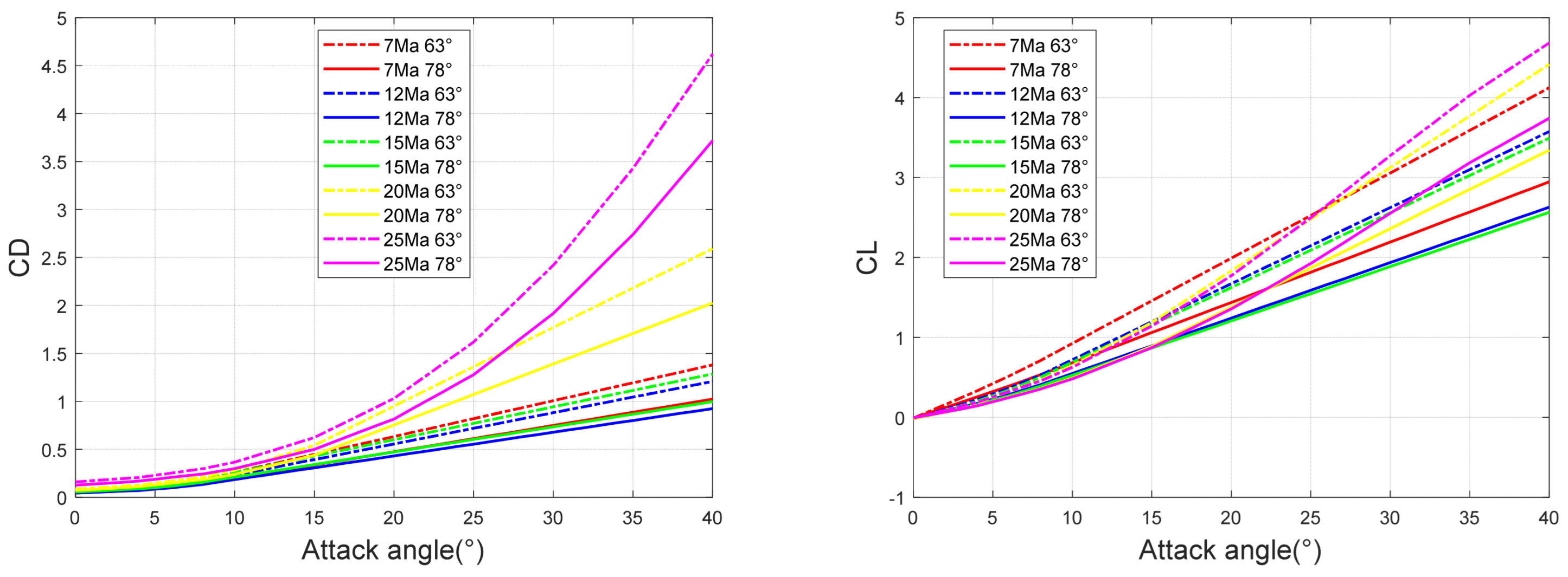
Figure 1. Drag coefficient and lift coefficient of two sweep angles at different working points.
Aerospace 10 01008 g001
Figure 2. Intelligent morphing decision-making method of hypersonic morphing vehicle based on a DNN.
Aerospace 10 01008 g002
Figure 3. Add interference schematics in segments.
Aerospace 10 01008 g003
Figure 4. Neural network decision sweep angle overall flow chart.
Aerospace 10 01008 g004
Figure 5. Deep neural network diagram.
Aerospace 10 01008 g005
Figure 6. The datum trajectory obtained from the nominal entry condition.
Aerospace 10 01008 g006
Figure 7. DNN network prediction output and error.
Aerospace 10 01008 g007
Figure 8. Glide trajectory and heat flux density, velocity, and sweep angle under drag disturbance.
Aerospace 10 01008 g008
Figure 9. Glide trajectory and heat flux density, velocity, and sweep angle under lift disturbance.
Aerospace 10 01008 g009
Table 1. Intelligent morphing decision pseudo-code.
Intelligent Morphing Decision-Making Based on a DNN
Generate trajectory samplewhile  Descend to terminal altitude
if  Follow the reference trajectory descend >3 km
    Add interference
    Update initial conditions
    Trajectory optimization
   end
end
Neural network trainingInput: Trajectory sample
1. The linear relation coefficient matrix W and deviation vector b of each hidden layer and output layer are initialized as a random value.
2. For iter from 1 to MAX
 2.1 For i = 1 to m
    (a) Set the input a l to DNN to x
(b) For i = 2… L, forward propagation computation
(c) Calculate the output layer output by the loss function
    (d) For i = 2… L, backpropagate the error
 2.2 For i = 2… L, update the W l and b l of layer l
 2.3 If all of the changes in W and b are less than the threshold for stopping the iteration, the loop goes to step 3
3. The linear relation coefficient matrix W and bias vector b of each hidden layer and output layer are output.
Intelligent decision processInput: V and H of the current state of the hypersonic vehicle
Process: Intelligent decision-making computing
Output: Sweep angle command
    Attack angle command
    Throttle command
Table 2. Optimize boundary condition settings.
Quantity of StateInitial Boundary ConstraintTerminal Boundary Constraint
Altitude (km)8045
Velocity (Ma)26.527
X-direction displacement (km)018,000
Y-direction displacement (km)08000
Table 3. Neural network training parameter settings.
Structure NameParameter Setting
Number of layers and number of neurons[36,36,12]
Number of iterations1500
Learning rate0.01
Maximum number of failures12
Target mean square error0.0004
Table 4. Test set RMSE for DNN and BPNN.
Attack AngleSweep AngleThrottle Coefficient
BP0.02620.00315.61 × 10−6
DNN0.00856.28 × 10−43.12 × 10⁻⁶
Table 5. Comparison of displacement distance between intelligent morphing and program morphing.
Lift Is Reduced by 5%Lift Is Increased by 5%Drag Reduced by 5%Drag Increased by 5%
Program morphing displacement (km)18,53320,46820,52918,557
Intelligent morphing displacement (km)18,73321,70821,68618,914
Disclaimer/Publisher’s Note: The statements, opinions and data contained in all publications are solely those of the individual author(s) and contributor(s) and not of MDPI and/or the editor(s). MDPI and/or the editor(s) disclaim responsibility for any injury to people or property resulting from any ideas, methods, instructions or products referred to in the content.